

Page 1

UD.6L0206D1136A01
Access Control Terminal
Quick Start Guide
Page 2
Access Control Terminal·Quick Start Guide
i
Quick Start Guide
© 2015 Hangzhou Hikvision Digital Technology Co., Ltd.
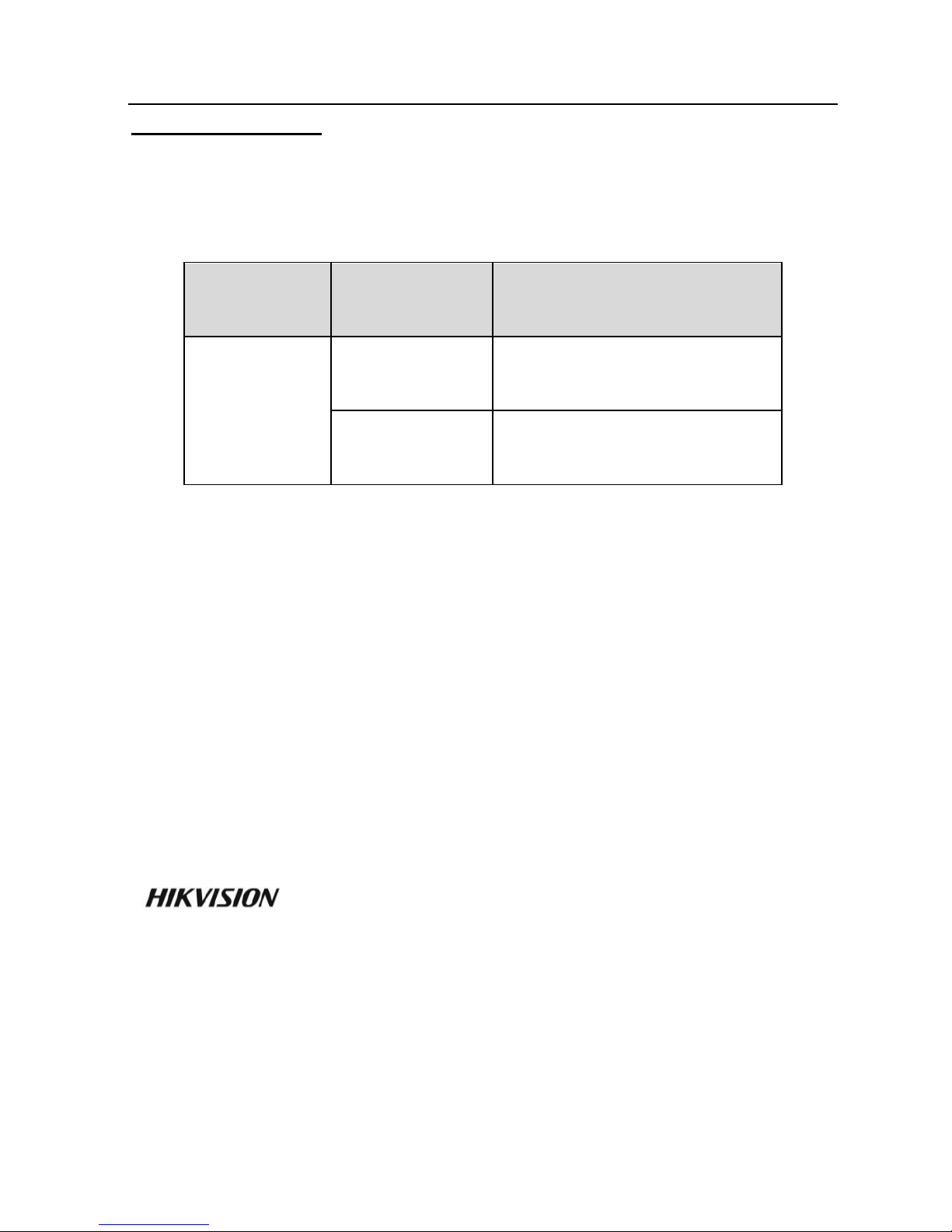
This quick start guide is applied for access control terminal.
Product
Serials
Model
Product Name
DS-K1T802
DS-K1T802E
Access Control Terminal
(EM Card)
DS-K1T802M
Access Control Terminal
(Mifare Card)
It includes instructions on how to use the Product. The software
embodied in the Product is governed by the user license
agreement covering that Product.
About this Manual
This Manual is subject to domestic and international copyright
protection. Hangzhou Hikvision Digital Technology Co., Ltd.
(“Hikvision”) reserves all rights to this manual. This manual cannot
be reproduced, changed, translated, or distributed, partially or
wholly, by any means, without the prior written permission of
Hikvision.
Trademarks
and other Hikvision marks are the property of
Hikvision and are registered trademarks or the subject of
applications for the same by Hikvision and/or its affiliates. Other
trademarks mentioned in this manual are the properties of their
respective owners. No right of license is given to use such
trademarks without express permission.
Page 3

Access Control Terminal·Quick Start Guide
ii
Disclaimer
TO THE MAXIMUM EXTENT PERMITTED BY APPLICABLE LAW,
HIKVISION MAKES NO WARRANTIES, EXPRESS OR IMPLIED,
INCLUDING WITHOUT LIMITATION THE IMPLIED WARRANTIES OF
MERCHANTABILITY AND FITNESS FOR A PARTICULAR PURPOSE,
REGARDING THIS MANUAL. HIKVISION DOES NOT WARRANT,
GUARANTEE, OR MAKE ANY REPRESENTATIONS REGARDING THE
USE OF THE MANUAL, OR THE CORRECTNESS, ACCURACY, OR
RELIABILITY OF INFORMATION CONTAINED HEREIN. YOUR USE OF
THIS MANUAL AND ANY RELIANCE ON THIS MANUAL SHALL BE
WHOLLY AT YOUR OWN RISK AND RESPONSIBILITY.
TO THE MAXIMUM EXTENT PERMITTED BY APPLICABLE LAW, IN
NO EVENT WILL HIKVISION, ITS DIRECTORS, OFFICERS, EMPLOYEES,
OR AGENTS BE LIABLE TO YOU FOR ANY SPECIAL,
CONSEQUENTIAL, INCIDENTAL, OR INDIRECT DAMAGES,
INCLUDING, AMONG OTHERS, DAMAGES FOR LOSS OF BUSINESS
PROFITS, BUSINESS INTERRUPTION, SECURITY BREACHES, OR LOSS
OF DATA OR DOCUMENTATION, IN CONNECTION WITH THE USE
OF OR RELIANCE ON THIS MANUAL, EVEN IF HIKVISION HAS BEEN
ADVISED OF THE POSSIBILITY OF SUCH DAMAGES.
SOME JURISDICTIONS DO NOT ALLOW THE EXCLUSION OR
LIMITATION OF LIABILITY OR CERTAIN DAMAGES, SO SOME OR ALL
OF THE ABOVE EXCLUSIONS OR LIMITATIONS MAY NOT APPLY TO
YOU.
Support
Should you have any questions, please do not hesitate to contact
your local dealer.
0100001051122
Page 4
Access Control Terminal·Quick Start Guide
iii
Regulatory Information
FCC Information
FCC compliance: This equipment has been tested and found to
comply with the limits for a digital device, pursuant to part 15 of
the FCC Rules. These limits are designed to provide reasonable
protection against harmful interference when the equipment is
operated in a commercial environment. This equipment generates,
uses, and can radiate radio frequency energy and, if not installed
and used in accordance with the instruction manual, may cause
harmful interference to radio communications. Operation of this
equipment in a residential area is likely to cause harmful
interference in which case the user will be required to correct the
interference at his own expense.
FCC Conditions
This device complies with part 15 of the FCC Rules. Operation is
subject to the following two conditions:
1. This device may not cause harmful interference.
2. This device must accept any interference received, including
interference that may cause undesired operation.
EU Conformity Statement
This product and - if applicable - the supplied
accessories too are marked with "CE" and comply
therefore with the applicable harmonized European
standards listed under the Low Voltage Directive 2006/95/EC, the
EMC Directive 2004/108/EC, the RoHS Directive 2011/65/EU.
2012/19/EU (WEEE directive): Products marked with
this symbol cannot be disposed of as unsorted
municipal waste in the European Union. For proper
recycling, return this product to your local supplier
upon the purchase of equivalent new equipment, or
dispose of it at designated collection points. For more information
see: www.recyclethis.info.
Page 5
Access Control Terminal·Quick Start Guide
iv
2006/66/EC (battery directive): This product contains
a battery that cannot be disposed of as unsorted
municipal waste in the European Union. See the
product documentation for specific battery
information. The battery is marked with this symbol,
which may include lettering to indicate cadmium (Cd), lead (Pb),
or mercury (Hg). For proper recycling, return the battery to your
supplier or to a designated collection point. For more information
see: www.recyclethis.info.
Industry Canada ICES-003 Compliance
This device meets the CAN ICES-3 (A)/NMB-3(A) standards
requirements.
Safety Instruction
These instructions are intended to ensure that user can use the
product correctly to avoid danger or property loss.
The precaution measure is divided into Warnings and Cautions:
Warnings: Neglecting any of the warnings may cause serious
injury or death.
Cautions: Neglecting any of the cautions may cause injury or
equipment damage.
Warnings
All the electronic operation should be strictly compliance with
the electrical safety regulations, fire prevention regulations and
other related regulations in your local region.
Warnings Follow these
safeguards to prevent
serious injury or death.
Cautions Follow these
precautions to prevent
potential injury or
material damage.
Page 6

Access Control Terminal·Quick Start Guide
v
Please use the power adapter, which is provided by normal
company. The power consumption cannot be less than the
required value.
Do not connect several devices to one power adapter as
adapter overload may cause over-heat or fire hazard.
Please make sure that the power has been disconnected before
you wire, install or dismantle the device.
When the product is installed on wall or ceiling, the device shall
be firmly fixed.
If smoke, odors or noise rise from the device, turn off the
power at once and unplug the power cable, and then please
contact the service center.
If the product does not work properly, please contact your
dealer or the nearest service center. Never attempt to
disassemble the device yourself. (We shall not assume any
responsibility for problems caused by unauthorized repair or
maintenance.)
Cautions
Do not drop the device or subject it to physical shock, and do
not expose it to high electromagnetism radiation. Avoid the
equipment installation on vibrations surface or places subject to
shock (ignorance can cause equipment damage).
Do not place the device in extremely hot (refer to the
specification of the device for the detailed operating
temperature), cold, dusty or damp locations, and do not expose
it to high electromagnetic radiation.
The device cover for indoor use shall be kept from rain and
moisture.
Exposing the equipment to direct sun light, low ventilation or
heat source such as heater or radiator is forbidden (ignorance
can cause fire danger).
Do not aim the device at the sun or extra bright places. A
blooming or smear may occur otherwise (which is not a
Page 7

Access Control Terminal·Quick Start Guide
vi
malfunction however), and affecting the endurance of sensor at
the same time.
Please use the provided glove when open up the device cover,
avoid direct contact with the device cover, because the acidic
sweat of the fingers may erode the surface coating of the device
cover.
Please use a soft and dry cloth when clean inside and outside
surfaces of the device cover, do not use alkaline detergents.
Please keep all wrappers after unpack them for future use. In
case of any failure occurred, you need to return the device to
the factory with the original wrapper. Transportation without
the original wrapper may result in damage on the device and
lead to additional costs.
Improper use or replacement of the battery may result in
hazard of explosion. Replace with the same or equivalent type
only. Dispose of used batteries according to the instructions
provided by the battery manufacturer.
Page 8

Access Control Terminal·Quick Start Guide
vii
Table of Contents
1 Overview ...................................................................................................... 1
1.1 Introduction ........................................................................... 1
1.2 Main Features ........................................................................ 1
2 Appearance .................................................................................................. 3
2.1 Appearance of the Termianl ................................................... 3
2.2 Description of Keypad Items .................................................. 4
3 Terminal Connection .................................................................................... 5
3.1 Terminal Description .............................................................. 5
3.2 External Device Wiring ........................................................... 6
4 Installation ................................................................................................... 7
4.1 Mounting with Gang Box ....................................................... 8
4.2 Mounting without Gang Box .................................................. 9
5 Activating the Access Control Terminal ....................................................... 11
5.1 Activating via SADP Software ............................................... 11
5.2 Activating via Client Software .............................................. 13
Page 9

Access Control Terminal·Quick Start Guide
1
1 Overview
1.1 Introduction
DS-K1T802 Series Standalone Access Control
Figure 1-1
Terminal
DS-K1T802 is a series of standalone access control terminal
designed with a LCD display screen. It supports TCP/IP
network communication, offline records storage functions
and so on.
1.2 Main Features
Equipped with 32-bit high-speed processor
Supports TCP/IP network communication, with
self-adaptive network interface. The communication
Page 10

Access Control Terminal·Quick Start Guide
2
data is specially encrypted to relieve the concern of
privacy leak
Supports EM card and Mifare card reading
Supports authentication methods of card, card and
password
Doorbell ring design
Supports time synchronization via NTP, manual or
automatic method
Supports online upgrade, and remote operation and
device rebooting control
The access controller can store 3 thousand legal cards
and 10 thousand card swiping records
Unlocking overtime alarm, invalid card swiping over
times alarm, blacklist alarm, and duress card/code
alarm
Supports various card types as normal/ disabled/
blacklist/ patrol/ guest/ duress/ super card, etc.
Data can be permanently saved after power-off
Accurate data and time display provided by built-in
electronic clock and watchdog program to ensure the
basic function of the terminal
Remotely device rebooting control
Supports alarm of offline event exceeding 90%
Page 11

Access Control Terminal·Quick Start Guide
3
2 Appearance
2.1 Appearance of the Termianl
Please refer to the following content for detailed
information of the terminal.
Appearance of Access Control Terminal Figure 2-1
Description of Access Control Terminal Table 2-1
No.
Name
Description
1
LCD
Display
Screen
First Line: display date
Second Line: display time
Third Line: display authentication
information or swiping status
2
Power
Indicator
Slow Flicking
Green
Card reader is
working properly.
Page 12

Access Control Terminal·Quick Start Guide
4
No.
Name
Description
2
Power
Indicator
Solid Green for
a period
The operation of
pressing keys or
swiping card is valid.
Solid Red for a
period
The operation of
pressing keys or
swiping card is
invalid.
3
Link
Indicator
Solid light
Normal
Off
Network Exception
4
Keypad
Numeric key 0 to 9, Clearing key *,
and Confirming key #
5
Door Bell
Door Bell Ring
2.2 Description of Keypad Items
Description of Keys Table 2-2
No.
Description
0 to 9
Numeric Keys: Enter number in the
textbox.
2 and 8
Direction Keys: Select icons in the menu.
*
Exiting Key: Click the key to exit the
menu.
#
Confirming Key: Click the key to confirm
operations.
Page 13

Access Control Terminal·Quick Start Guide
5
3 Terminal Connection
3.1 Terminal Description
The following table shows the terminals description
Terminal Description Table 3-1
Description
Color
Power Input
12VDC
Red
GND
Black
Bell
Bell+
Orange
Bell-
Yellow
Door Lock
BUTTON_IN
Purple
DOOR_COM
Green
DOOR_NO/NC
Blue
SENSOR_IN
White
GND
Black
12V_LOCK
Brown
Page 14

Access Control Terminal·Quick Start Guide
6
3.2 External Device Wiring
Power Supply Wiring
Doorbell Wiring
Power Supply
Figure 3-1
Connection Diagram
Doorbell Wiring
Figure 3-2
Diagram
Door Button Wiring
Door Lock Wiring
Door Button Wiring
Figure 3-3
Diagram
Door Lock Wiring
Figure 3-4
Diagram
Page 15

Access Control Terminal·Quick Start Guide
7
Door Magnetic Wiring
Door Magnetic Wiring Diagram
Figure 3-5
4 Installation
Before you start
Please make sure that the device in the package is in
good condition and all the assembly parts are included.
Make sure that all the related equipment is power-off
during the installation.
Check the specification of the products for the
installation environment.
Check whether the power supply is matched with your
AC outlet to avoid damage.
Page 16

Access Control Terminal·Quick Start Guide
8
If the product does not function properly, please contact
your dealer or the nearest service center. Do not
disassemble the camera for repair or maintenance by
yourself.
Please make sure the wall is strong enough to withstand
three times the weight of the camera and the mounting.
4.1 Mounting with Gang Box
Steps:
1. Route the cables through the cable hole of the mounting
base.
2. Align the screw holes on mounting base with the screw
holes on gang box.
3. Fix the mounting base on the gang box with inserting
two KA4*22-SUS screws (supplied) into the two screw
holes.
Install the
Figure 4-1
Mounting Base
Attach the
Figure 4-2
Front Cover
Page 17

Access Control Terminal·Quick Start Guide
9
4. Connect the corresponded cables.
5. Align the buckle of the front cover with the slot of the
mounting base, and hang the front cover onto the
mounting base. Make sure the buckle is embedded into
the slot.
6. Secure the front cover with inserting and tightening two
screws on the bottom of device.
Secure the Front Cover Figure 4-3
4.2 Mounting without Gang Box
Steps:
1. Drill 4 screw holes in the wall according to the holes of
the mounting base, and then insert expansion screws
sockets (not supplied) into the holes.
2. Route the cables through the cable hole of the mounting
base.
3. Align the screw holes on the base with the screw sockets
on the wall.
4. Attach the mounting base on the wall with Inserting 4
KA4*22-SUS screws (supplied) into the 4 screw sockets.
Page 18

Access Control Terminal·Quick Start Guide
10
Install the
Figure 4-4
Mounting Base
Attach the Front
Figure 4-5
Cover
5. Connect the corresponded cables.
6. Align the buckle of the front cover with the slot of the
mounting base, and hang the front cover onto the
mounting base. Make sure the buckle is embedded into
the slot.
7. Secure the front cover with inserting and tightening two
screws on the bottom of device.
Secure the Front Cover Figure 4-6
Page 19

Access Control Terminal·Quick Start Guide
11
5 Activating the Access Control
Terminal
Purpose:
You are required to activate the terminal first before using
it.
Activation via SADP, and Activation via client software are
supported.
The default values of the control terminal are as follows.
The default IP address: 192.0.0.64.
The default port No.: 8000.
The default user name: admin.
5.1 Activating via SADP Software
SADP software is used for detecting the online device,
activating the device, and resetting the password.
Get the SADP software from the supplied disk or the
official website, and install the SADP according to the
prompts. Follow the steps to activate the control panel.
Steps:
1. Run the SADP software to search the online devices.
2. Check the device status from the device list, and select
an inactive device.
Page 20

Access Control Terminal·Quick Start Guide
12
SADP Interface Figure 5-1
3. Create a password and input the password in the
password field, and confirm the password.
STRONG PASSWORD RECOMMENDED– We
highly recommend you create a strong
password of your own choosing (using a
minimum of 8 characters, including upper
case letters, lower case letters, numbers, and
special characters) in order to increase the
security of your product. And we recommend
you reset your password regularly, especially
in the high security system, resetting the
password monthly or weekly can better
protect your product.
Page 21

Access Control Terminal·Quick Start Guide
13
4. Click OK to save the password.
You can check whether the activation is completed on
the pop-up window.
If activation failed, please make sure that the password
meets the requirement and then try again.
5. Change the device IP address to the same subnet with
your computer by modifying the IP address manually.
Modify Network Parameters Interface Figure 5-2
6. Input the password and click the Save button to
activate your IP address modification.
5.2 Activating via Client Software
The client software is versatile video management
software for multiple kinds of devices.
Page 22

Access Control Terminal·Quick Start Guide
14
Get the client software from the supplied disk or the
official website, and install the software according to the
prompts. Follow the steps to activate the control panel.
Steps:
1. Run the client software and the control panel of the
software pops up, as shown in the figure below.
2. Click the icon on the upper-left side of the page,
select Access Control to enter the control panel.
Control Panel Interface Figure 5-3
3. Click the Controller Management icon to enter the
Controller Management interface, as shown in the
Page 23

Access Control Terminal·Quick Start Guide
15
figure below.
Device List Figure 5-4
4. Check the device status from the device list, and select
an inactive device.
5. Click the Activate button to pop up the Activation
interface.
List Selecting Interface Figure 5-5
6. Create a password and input the password in the
password field, and confirm the password.
Page 24

Access Control Terminal·Quick Start Guide
16
STRONG PASSWORD RECOMMENDED– We highly
recommend you create a strong password of your
own choosing (using a minimum of 8 characters,
including upper case letters, lower case letters,
numbers, and special characters) in order to increase
the security of your product. And we recommend you
reset your password regularly, especially in the high
security system, resetting the password monthly or
weekly can better protect your product.
7. Click OK button to start activation.
8. Click the button to pop up the Network
Parameter Modification interface.
9. Change the device IP address to the same subnet with your
computer by modifying the IP address manually.
10. Input the password to activate your IP address modification.
 Loading...