How it Works
Log In / Sign Up
Buy Points
How it Works
FAQ
Contact Us
Questions and Suggestions
Users
Hikvision
Loading...
D
DS-K1102MK
5
DS-K1103C
2
DS-K1103CK
2
DS-K1103M
3
DS-K1103MK
3
DS-K1104C
DS-K1104M
4
DS-K1104MK
4
DS-K1106C
DS-K1106M
DS-K1106S
DS-K1107
DS-K1107E
DS-K1107EK
DS-K1107M
3
DS-K1107MK
3
DS-K1108AD
DS-K1108E
DS-K1108EK
DS-K1108M
DS-K1108MK
DS-K1200
2
DS-K1200EF
2
DS-K1200MF
2
DS-K1201EF
DS-K1201MF
2
DS-K1201SF
DS-K170HPK
DS-K1801
DS-K182HP
DS-K1A801EF
DS-K1A801F
DS-K1A801MF
DS-K1A8503EF
DS-K1A8503EF-B
DS-K1A8503F
DS-K1A8503F-B
DS-K1A8503MF
DS-K1A8503MF-B
DS-K1F100-D8E
2
DS-K1F820-F
2
DS-K1T105E
3
DS-K1T105E-C
4
DS-K1T105E/M
DS-K1T105E/M-C
DS-K1T105M-C
DS-K1T200EF-C
DS-K1T200EF/MF
DS-K1T200EF/MF-C
DS-K1T200MF-C
DS-K1T331W
2
DS-K1T341A
DS-K1T500S
3
DS-K1T501SF
3
DS-K1T604M
2
DS-K1T604MF
2
DS-K1T604MFR
DS-K1T605E
2
DS-K1T605EF
2
DS-K1T605M
2
DS-K1T605MF
2
DS-K1T605MF-B
2
DS-K1T607E
DS-K1T607EF
DS-K1T607M
DS-K1T607MF
DS-K1T607MFW
DS-K1T607MW
DS-K1T607PE
DS-K1T607PEF
DS-K1T607PMFW
DS-K1T607PMW
DS-K1T607TE
DS-K1T607TEF
DS-K1T607TM
DS-K1T607TMF
DS-K1T607TMFWW
DS-K1T607TMW
DS-K1T671
DS-K1T671M
2
DS-K1T671TM-3XF
DS-K1T680
DS-K1T680D
DS-K1T680D-E1
DS-K1T680DF
DS-K1T680DF-E1
DS-K1T680DFG
DS-K1T680DFG1
DS-K1T680DFW
DS-K1T680DG
DS-K1T680DG1
DS-K1T680DW
DS-K1T802E
2
DS-K1T802M
2
DS-K1T803EF
2
DS-K1T803EF-1
DS-K1T803F
DS-K1T803F-1
DS-K1T803MF
2
DS-K1T803MF-1
Loading...
Loading...
Nothing found
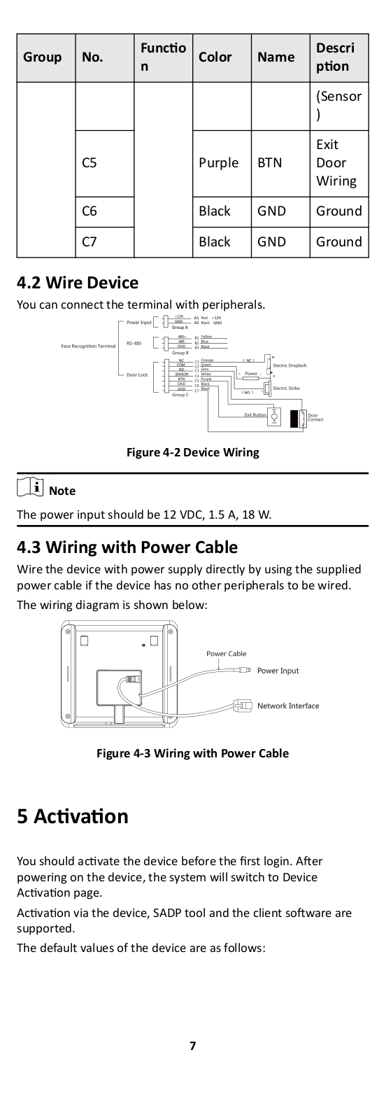
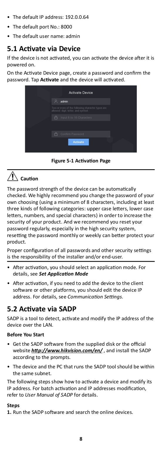
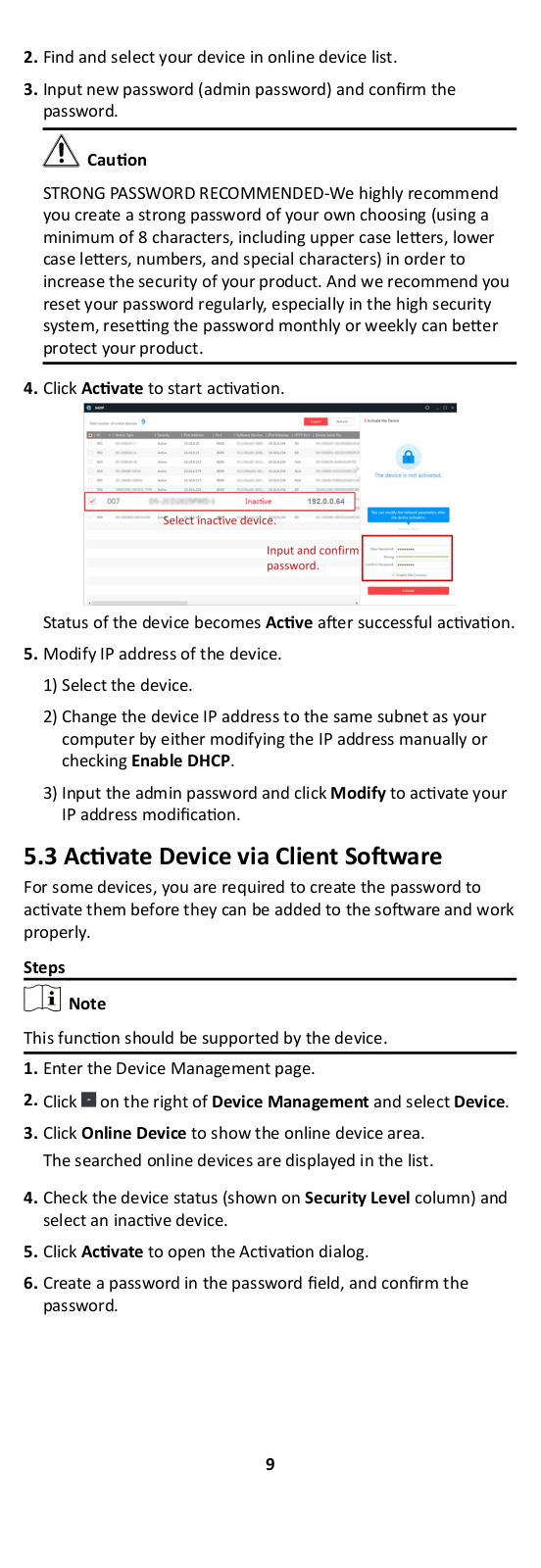
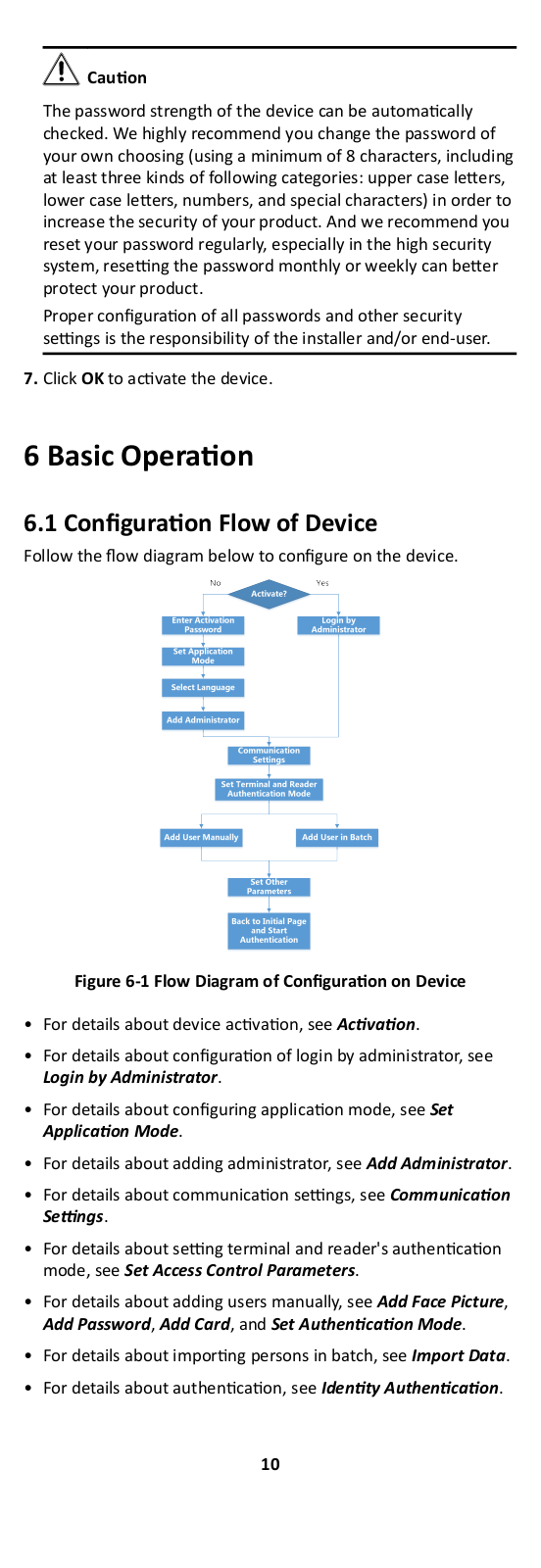
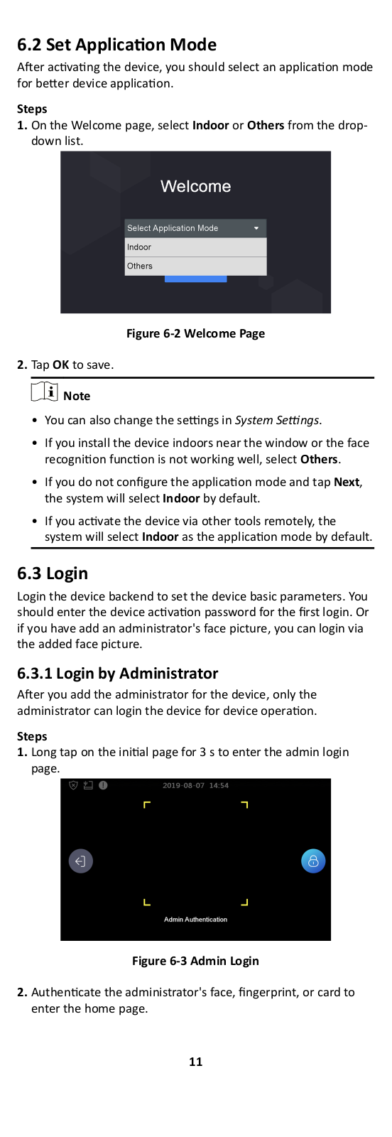
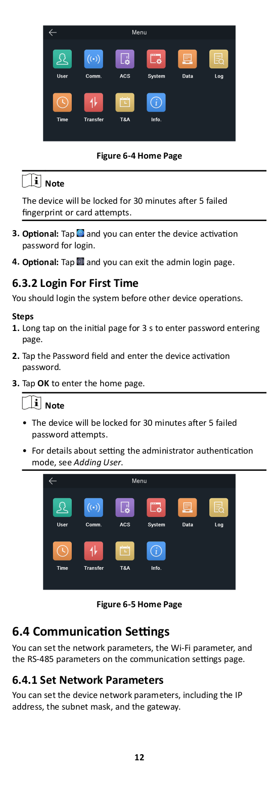
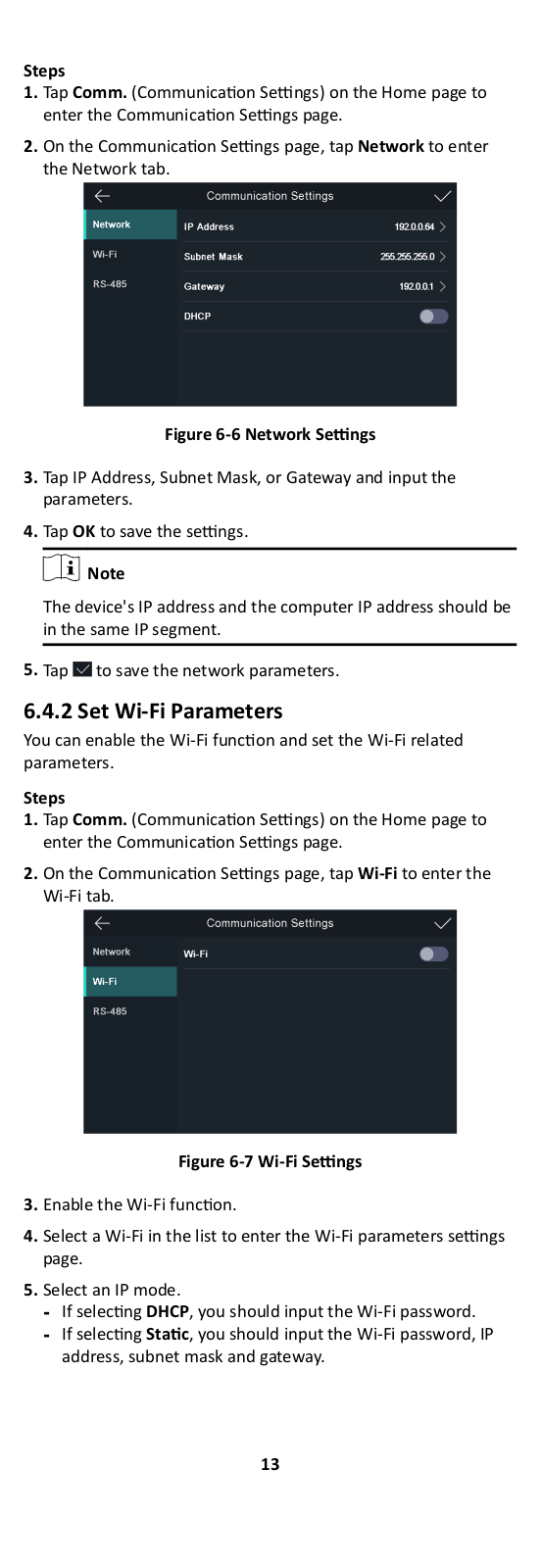
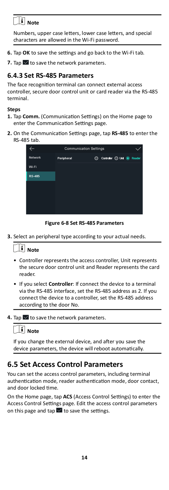
DS-K1T331W
operation manual
118 pgs
11.05 Mb
0
User Manual
3 pgs
2.35 Mb
0
Table of contents
Loading...
Hikvision DS-K1T331W operation manual
...
Hikvision operation manual
Download
Specifications and Main Features
Frequently Asked Questions
User Manual
Download
Loading...
+
hidden pages
Unhide
You need points to download manuals.
1 point = 1 manual.
You can buy points or you can get point for every manual you upload.
Buy points
Upload your manuals