

Page 1
harman/kardon
AVR254
7 X 50W 7.1 CHANNEL A/V RECEIVER
SERVICE MANUAL
CONTENTS
ESD WAR N ING……………………………….2
LEAKAGE TESTING……………….…..…....3
BASIC SPECIFICATIONS…………………..4
PACKAGING…………………………….……5
FRO NT PANEL CO NTRO L S ………..…..…..6
REAR PANEL CONNECTIONS………….…9
REMOTE CONTROL FUNCTIONS……….12
CONNECTIONS/INSTALLATION………....15
OPERATION………………………...………28
TROUBLESHOOTING GUIDE…...……..…32
REMOTE & PR OCESSOR R ESETS……....33
harman/k ar don, Inc.
250 Crossways Park Dr.
Released 2008 Woodbur y, New York 11797 Rev0 5/2008
Discontinued XXXX
DISASSEM BLY…...…………………………..34
UNIT EXPLOD ED VI EW…………..…….…..35
EXPLODED VIEW PARTS LIST……………36
AMP BIAS ADJUSTMENT……………….…37
BLOCK DIAGRAM…………………………..38
PCB DRAWINGS……………………………39
ELECTRICAL PARTS LIST………..….……46
SEMICONDUCTOR PINOUTS…….………88
SCHEMATICS……………………………….176
WIRING DIAGRAM………………………….189
Page 2

AVR254
harman/kardon
Some semiconductor (solid state) devices can be damaged easily by static electricity . Such components commonly are called
Electrostatically Sensitive (ES) Devices. Examples of typical ES devices are integrated circuits and some field effect transistors and
semiconductor "chip" components.
The following techniques should be used to help reduce the incidence of component damage caused by static electricity.
1. Immediately before handling any semiconductor component or semiconductor -equippedassembly,drain off any electrostatic charge on
your body by touching a known earth ground. Alternatively, obtain and wear a commercially available discharging wrist strap device,
which should be removed for potential shock reasons prior to applying power to the unit under test.
2. After removing an electrical assembly equipped with ES devices, place the assembly on a conductive surface such as aluminum foil, to
prevent electrostatic charge build-up or exposure of the assembly .
3. Use only a grounded-tip soldering iron to solder or unsolder ES devices.
4. Use only an anti-static solder removal device. Some solder removal devices not classified as "anti-static" can generate electrical charges
sufficient to damage ES devices.
5. Do not use freon-propelled chemicals. These can generate electrical change sufficient to damage ES devices.
6. Do not remove a replacement ES devicefrom its protective package until immediately before you are ready to install it.(Most replacement
ES devices are packaged with leads electrically shorted together by conductive foam, aluminum foil or comparable conductive material.)
7. Immediately before removing the protective material from the leads of a replacement ES device, touch the protective material to the
chassis or circuit assembly into which the device will be installed.
CAUTION :
8. Minimize bodily motions when handling unpackaged replacement ES devices. (Otherwise harmless motion such as the brushing together
or your clothes fabric or the lifting of your foot from a carpeted floor can generate static electricity sufficient to damage an ES devices.
Be sure no power is applied to the chassis or circuit, and observe all other safety precautions.
Eachprecautioninthismanualshouldbefollowedduringservicing.
Components identified with the IEC symbol in the parts list are special significance to safety .When replacing a component identified with
, use only the replacement parts designated, or parts with the same ratings or resistance, wattage, or voltage that are designated in the
parts list in this manual. Leakage-current or resistance measurements must be made to determine that exposed parts are acceptably
insulated from the supply circuit before retuming the product to the customer.
Page 3
SAFETY PRECAUTIONS
The following check should be performed for the continued
protection of the customer and service technician.
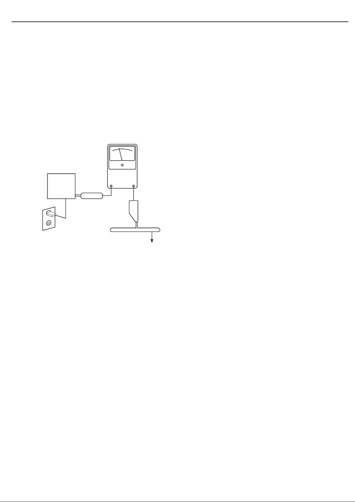
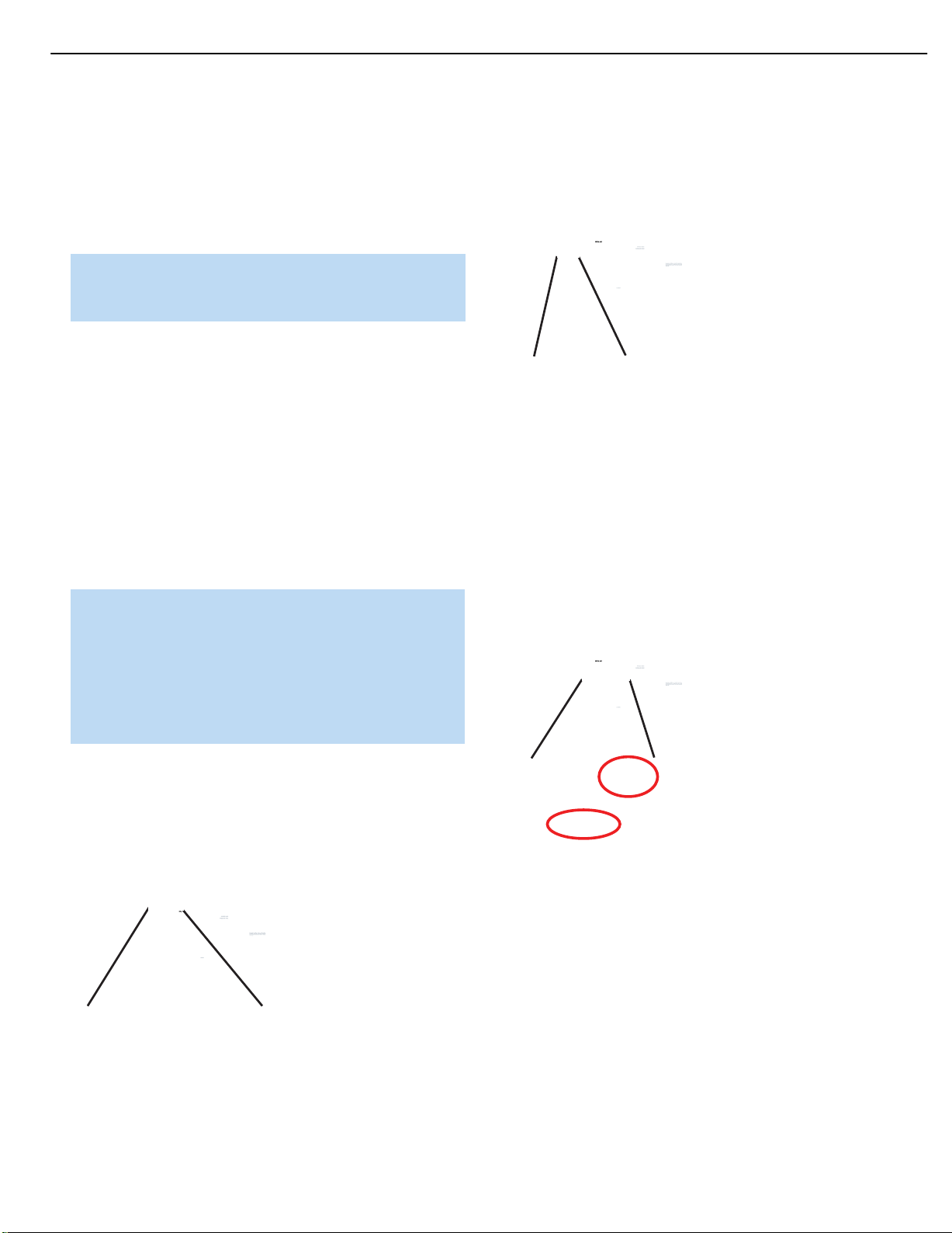
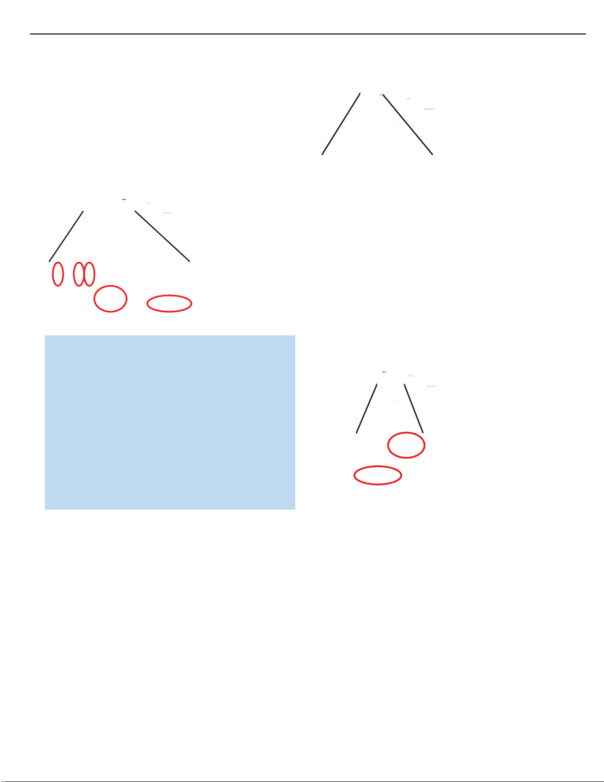
LEAKAGE CURRENT CHECK
Measure leakage current to a known earth ground (water
pipe, conduit, etc.) by connecting a leakage current tester
between the earth ground and all exposed metal parts of the
appliance (input/output terminals, screwheads, metal
overlays, control shaft, etc.). Plug the AC line cord of the
appliance directly into a 120V AC 60Hz outlet and turn the
AC power switch on. Any current measured must not exceed
o.5mA.
ANY MEASUREMENTS NOT WITHIN THE LIMITS
OUTLINED ABOVE ARE INDICATIVE OF A
POTENTIAL SHOCK HAZARD AND MUST BE
CORRECTED BEFORE RETURNING THE APPLIANCE
TO THE CUSTOMER.
3
AVR254
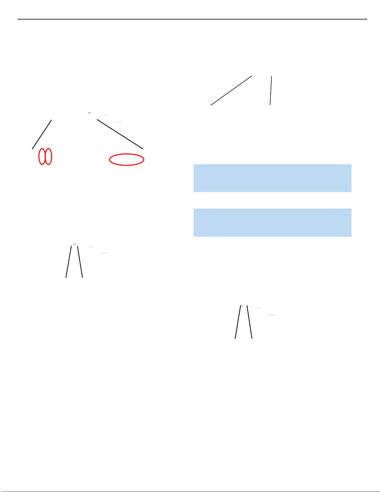
Reading should
not be above
0.5mA
Device
under
test
Leakage
current
tester
harman/kardon
Test all
exposed metal
surfaces
Also test with
plug reversed
(Using AC adapter
plug as required)
Earth
ground
AC Leakage Test
Page 4

4
AVR254
harman/kardon
AVR 254 TECHNICAL SPECIFICATIONS
Audio Section
Stereo Mode
Continuous Average Power (FTC)
65 Watts per channel,20Hz–20kHz,
@ <0.07% THD, both channels driven into 8 ohms
Seven-Channel Surround Modes
Power per Individual Channel
Front L & R channels:
50 Watts per channel
@ <0.07% THD, 20Hz–20kHz into 8 ohms
Center channel:
50 Watts @ <0.07% THD,20Hz–20kHz into 8 ohms
Surround (L & R Side, L & R Back) channels:
50 Watts per channel
@ <0.07% THD, 20Hz–20kHz into 8 ohms
Input Sensitivity/Impedance
Linear (High-Level) 200mV/47k ohms
Signal-to-Noise Ratio (IHF-A) 100dB
Surround System Adjacent Channel Separation
Pro Logic I/II 40dB
Dolby Digital (AC-3) 55dB
DTS 55dB
Frequency Response
@ 1W (+0dB,–3dB) 10Hz – 130kHz
High Instantaneous
Current Capability (HCC) ±35 Amps
Transient Intermodulation
Distortion (TIM) Unmeasurable
Slew Rate 40V/µsec
FM Tuner Section
Frequency Range 87.5–108.0MHz
Usable Sensitivity IHF 1.3µV/13.2dBf
Signal-to-Noise Ratio Mono/Stereo 70/68dB
Distortion Mono/Stereo 0.2/0.3%
Stereo Separation 40dB @ 1kHz
Selectivity ±400kHz, 70dB
Image Rejection 80dB
IF Rejection 90dB
Please register your AVR 254 on our Web site at
www.harmankardon.com.
NOTE:
You’ll need the product’s serial number.
At the same time,you can choose to be notified about
our new products and/or special promotions.
AM Tuner Section
Frequency Range 520–1720kHz
Signal-to-Noise Ratio 45dB
Usable Sensitivity Loop 500 µV
Distortion 1kHz, 50% Mod 0.8%
Selectivity ±10kHz, 30dB
Video Section
Television Format NTSC
Input Level/Impedance 1Vp-p /75 ohms
Output Level/Impedance 1Vp-p /75 ohms
Video Frequency Response
(Composite and S-Video) 10Hz–8MHz (–3dB)
Video Frequency Response
(Component Video) 10Hz–100MHz (–3dB)
™
HDMI
General
Power Requirement AC 120V/60Hz
Power Consumption 65W idle,540W maximum
Dimensions (Product) (Shipping)
Width 17-5/16 inches (440mm) 21-7/8 inches (555mm)
Height 6-1/2 inches (165mm) 10-1/2 inches (266mm)
Depth 15 inches (382mm) 18-5/16 inches (465mm)
Weight 27.1 lb (12.3kg) 32.8 lb (14.9kg)
Depth measurement includes knobs,buttons and ter minal connections.
Height measurement includes feet and chassis.
All features and specifications are subject to change without notice.
Harman Kardon and Logic 7 are trademarks of Harman International Industries,Incorporated, registered
in the United States and/or other countries.EzSet/EQ, Designed to Entertain and The Bridge logo are trademarks
of Harman International Industries,Incorporated.
iPod is a trademark of Apple Inc., registered in the U.S. and other countries.
Audiovox is a registered trademark of Audiovox Corporation.
Blu-ray Disc is a trademark of the Blu-ray Disc Association.
CEA is a registered trademark of the Consumer Electronics Association.
Cirrus Logic is a registered trademark of Cirrus Logic,Inc.
Dolby and Pro Logic are registered trademarks,and MLP Lossless is a trademark, of Dolby Laboratories.
Manufactured under license from Dolby Laboratories.Dolby and the double-D symbol are trademarks of
Dolby Laboratories.Copyright 1999-2004 Dolby Laboratories. All rights reserved.
DTS,DTS-ES and DTS Neo:6 are registered trademarks,and DTS 96/24, DTS-HD and
DTS-HD Master Audio are trademarks, of DTS, Inc. Manufactured under license under U.S. Patent #’s:
5,451,942; 5,956,674; 5,974,380; 5,978,762; 6,226,616; 6,487,535; 7,003,467 and other
U.S. and worldwide patents issued and pending.© 1996-2007 DTS,Inc. All Rights Reserved.
Faroudja DCDi Cinema is a registered trademark of Genesis Microchip Inc.
HD-DVD is a trademark of the DVD Format/Logo Licensing Corporation (DVD FLLC).
HDMI is a trademark or registered trademark of HDMI Licensing LLC.
SACD is a trademark of Sony Corporation.
TiVo is a registered trademark of TiVo Inc.
XM and XM Ready are registered trademarks of XM Satellite Radio.
Version 1.3a with 10-bit Deep Color
(7 channels driven)
(Product) (Shipping)
Page 5

5
AVR254
1. Instruction manual ass'y - Accessories
1
2
POLY BAG
CARD WARRANTY
3
AM LOOP ANTENNA ASS'Y
harman/kardon
MICROPHONE ASS'Y
6
MANUAL ASS'Y
1
4
MANUAL INSTRUCTION
SHEET GUIDE
10
IMAGE BROCHURES
5
FM 1 POLE ANT(UL)
87
STAPLE
NO DESCRIPTION PARTS NO. Q,ty
1
CARD WARRANTY
2
3
AM LOOP ANTENNA
4
INSTRUCTION MANUAL
5
FM 1 POL ANT(UL)
6
REMOCON TRANSMITTER ASS'Y
7
SHEET GUIDE(QUICK START GUIDE)
STAPLE8 CPL0905
COVER ASS'Y CGRAVR154ZA 1
9
1
COVER A
2
COVER B
3
SHEET,FRONT COVER
4
PAD, COVER
5
BAG,POLY
IMAGE BROCHURES10 HQE1A273Z 1
6
REMOCON
TRANSMITTER ASS'Y
9
COVER ASS'Y
CPB1061WPOLY BAG
CQE1A172X 1
CSA1A020Z
CQX1A1310Z
visit www.harmankardon.com
CSA1A019Z 1
CARTAVR254
CQE1A380Z
CGR1A331H63
CGR1A332H63
CQE1A219Z
CPS1A676
CPB1A176Z
2
SNOW PAD (L)
SNOW PAD (R)
3
SET
4
BOX ,OUT CARTON
5
1
1
1
1
1
1
3
1
11
1
1
1
Item Description Part Number Qty
1 Manual, remote, antenna ass’y 1
2 Foam End Pad, Left CPS5A564Z 1
3 Foam End Pad, Right CPS5A565Z 1
4 AVR254 Receiver AVR 254 1
5 AVR254 Outer Carton CPG1A854Y 1
6 Microphone Assembly CJXAVR340MICRO 1
Page 6

6
AVR254
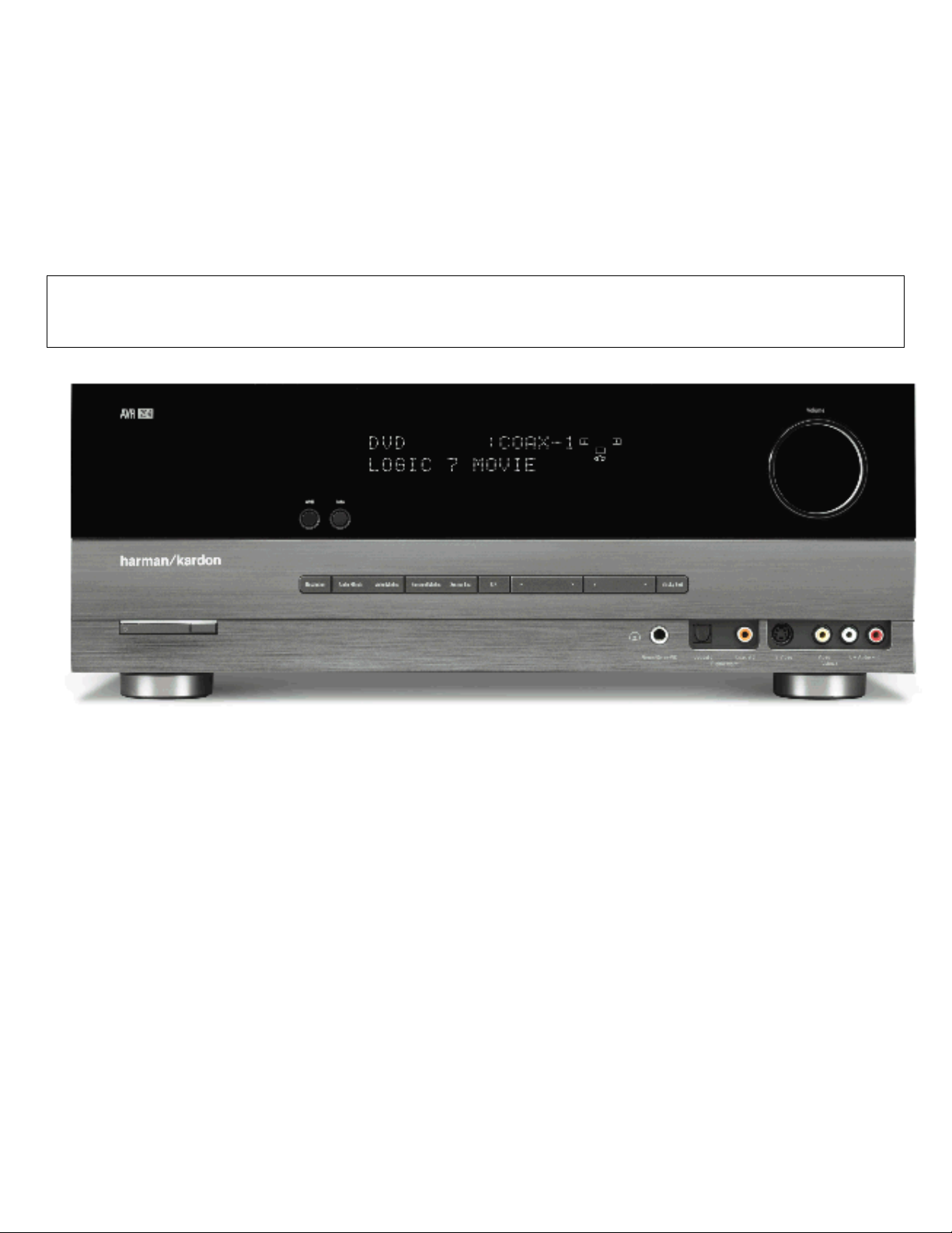
FRONT-PANEL CONTROLS
Main Power Switch:This mechanical switch turns the power supply
on or off. It is usually left pressed in (On position), and cannot be turned
on using the remote control.
Standby/On Switch: This electrical switch turns the receiver on
for playback, or leaves it in Standby mode for quick turn-on using this
switch or the remote control.
See the Advanced Functions section for more information on surround
modes.
Analog Audio,Video and Digital Audio Inputs: Connect a
source component that will only be used temporarily, such as a digital
camera or game console,to these jacks.Use only one type of audio
and one type of video connection.
Power Indicator:This LED has four possible modes:
• Main Power Off: When the AVR is unplugged or the Main Power
Switch is off, this LED is off.
• Standby: The LED is amber, indicating that the AVR is ready to
be turned on.
• On: The LED is white,when the AVR is on and operating normally.
• Protect: If the PROTECT message ever appears,tur n off the AVR
and unplug it. Check all speaker wires for a possible short. If none is
found, bring the unit to an authorized Harman Kardon service center
for inspection and repair before using it again.
Source List: Press this button to select a source device,which
is a component where a playback signal originates,such as DVD,
cable TV, satellite or the tuner.
Volume Knob:Turn this knob to raise or lower the volume.
Message Display:Various messages appear in this two-line display
in response to commands and changes in the incoming signal. In normal
operation, the current source name appears on the upper line,while the
surround mode is displayed on the lower line.When the on-screen display menu system (OSD) is in use,the current menu settings appear.
Headphone Jack/EzSet/EQ Microphone Input: Plug a 1/4"
headphone plug into this jack for private listening.
This jack is also used to connect the supplied microphone for the
EzSet/EQ procedure described in the Initial Setup section.To begin
EzSet/EQ,plug the supplied microphone into this jack, place the microphone at the listening position, and follow the directions given in the
Speaker Setup-Automatic Setup-EzSet/EQ on-screen menu.
NOTES:
• Each of these connections (analog audio,digital audio and
video) may be independently assigned to any source.See the
Initial Setup section for information on setting up sources,
including assigning audio and video inputs to a source.
• Although these jacks are labeled Optical 3,Coaxial 3 and
Video 4 on the AVR, the AVR’s menus refer to them as the
Optical Front, Coaxial Front,Composite Front, S-Video Front
and Analog Front inputs.
Speaker/Channel Input Indicators:The box icons indicate
which speaker positions you have configured (see the Initial Setup
Section), and the size (frequency range) of each speaker.The letters
will light inside the boxes to indicate which channels are present in
the incoming signal.
Navigation: These buttons are used to navigate the AVR’s menus
and to operate the tuner.
Remote IR Sensor:This sensor receives infrared (IR) commands
from the remote control. It is important to ensure that it is not blocked.
If covering the sensor is unavoidable,such as when the AVR 254 is
placed inside a cabinet, you may use an optional Harman Kardon
HE 1000, or other infrared receiver, connecting it to the Remote IR
Input on the AVR 254’s rear panel.Alter natively,connect the Remote IR
Output of another compatible component to the AVR 254’s Remote
IR Input. Point the remote at the other device’s remote sensor, and the
command will be transmitted to the AVR 254. An external IR “blaster”
may also be used, positioned to point at this area.
AVR Settings Button:Press this button to access the AVR’s
main menu.
Info Settings Button: Press this button to directly access the
Surround Modes: Press this button to select a surround sound
(e.g., multichannel) mode.The Surround Modes menu will appear on
screen, and the menu line will appear in the front-panel display.
AVR’s Source Info submenu,which contains the settings for the
current source.
Resolution: Each press of this button changes the AVR’s video output
⁄/¤
Use the front-panel or remote
menu line:Auto Select, Virtual Surround, Stereo,Movie,Music or Video
Game.Each line represents a type of audio signal, and is set to the
preferred surround mode that you manually select.
Press the OK Button when the menu line is highlighted, and the
available surround mode options for the current signal will appear.
⁄/¤
Use the
OK Button to engage it. Press the Back/Exit Button to exit the Surround
Modes menu.
Buttons to select the desired mode,and press the
Buttons to highlight a different
resolution to these settings: 480i, 480p, 720p,1080i or 1080p.
IMPORTANT NOTE: If the AVR’s video output resolution is set
higher than the capabilities of the actual connection, you will not
see a picture.If the best video connection from the AVR to the
TV is either composite or S-video,press this button until the
resolution is set to 480i.
harman/kardon
Page 7
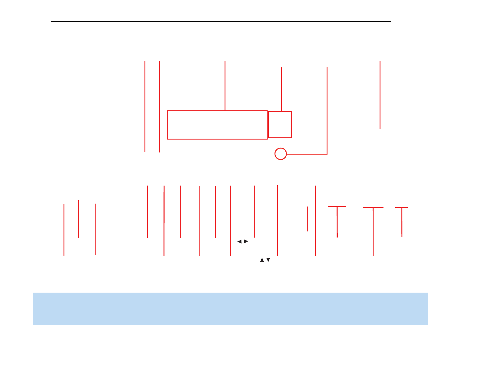
Resolution
Source
List
Navigation
Video
Modes
OK
Back/
Exit
Navigation
Headphone
Jack/EzSet/EQ
Microphone
Input
Digital
Audio Inputs
(Optical 3 and
Coaxial 3)
Video 4
Video Inputs
Video 4 Analog
Audio Inputs
Surround
Modes
Audio
Effects
AVR Info
Power
Indicator
Main Power
Switch
Standby/On
Switch
Volume
Message Display
Speaker/Channel
Input Indicators
Remote
IR Sensor
/
/
7
AVR254
harman/kardon
NOTE: To make it easier to follow the instructions throughout the manual that refer to this illustration, a copy of this page may be downloaded from the Product Support section at
www.harmankardon.com.
Page 8

8
AVR254
FRONT-PANEL CONNECTIONS
Audio Effects: Press this button to directly access the Audio Effects
submenu, which allows adjustment of the tone and other controls.
See the Initial Setup section for more information.
Video Modes: Press this button for direct access to the Video Modes
submenu, which contains settings that may be used to improve the
picture if necessary after you have adjusted the picture settings using
the video display or TV.
OK: Press this button to select the currently highlighted item.
Back/Exit: Press this button to return to the previous menu, or
to exit the menu system.
harman/kardon
Page 9

9
AVR254
REAR-PANEL CONNECTIONS
AM and FM Antenna Terminals: Connect the included AM
and FM antennas to their respective terminals for radio reception.
XM Antenna Jack: Plug in an XM Connect and Play or Mini Tuner
antenna module here.The XM antenna module is purchased separately,
and should specify that it is for home use with an XM Ready
You will need to subscribe to the XM service, which is available separately, and activate the service for your antenna module.(XM service
is not available in Alaska and Hawaii.)
Front,Center and Surround Speaker Outputs: Use two-
conductor speaker wire to connect each set of terminals to the correct
speaker. Remember to observe the correct polarity (positive and negative
connections).Always connect the positive lead to the colored terminal
on the receiver and the red terminal on the speaker. Connect the negative
lead to the black terminal on both the receiver and the speaker. See the
Connections section for more information on connecting your speakers.
®
product.
Surround Back/Zone 2 Speaker Outputs:These speaker
outputs are used for the surround back channels in a 7.1-channel home
theater, or may be reassigned to a remote room for multizone operation.
When these outputs are reassigned for multizone operation, only a
5.1-channel configuration will be available in the main listening room.
Use the on-screen menu system to configure these channels as desired.
As with the other speaker outputs,remember to observe proper polarity
by connecting the positive and negative output terminals to the corresponding terminals on each speaker.
Subwoofer Output: If you have a powered subwoofer with a
line-level input, connect it to this jack.
Preamp Outputs: Connect these jacks to an external amplifier if
more power is desired.
The Surround Back/Zone 2 Preamp Outputs may be used with an
external amplifier to power the surround back channels,or to power
the remote zone of a multizone system. Use the on-screen menu
system to configure these channels as desired.
Remote Infrared (IR) Input and Output:When the remote IR
receiver on the front panel is blocked, such as when the AVR is placed
inside a cabinet, connect an optional IR receiver to the Remote IR Input
jack for use with the remote control.The Remote IR Output may be
connected to the Remote IR Input of a compatible product to enable
remote control through the AVR. This is particularly useful in multizone
applications to control a source device from the remote room (when
used with the Zone 2 IR Input).When several source devices are used,
connect them in “daisy chain”fashion.
Zone 2 Infrared (IR) Input: Connect a remote IR receiver located
in the remote zone of a multizone system to this jack to control the AVR
(and any source devices connected to the Remote IR Output) from the
remote zone.
Composite and S-Video 1, 2 and 3 Video Inputs:These
jacks may be used to connect your video-capable source components
(e.g.,VCR, DVD player,cable TV box) to the receiver. Use only one type
of video connection for each source.These inputs are assignable, which
means they may be paired with any analog or digital audio inputs.This
will be explained in more detail in subsequent sections of this manual.
NOTE: The Video 2 inputs are associated with a set of outputs.
Consider connecting a video recorder here.
Composite and S-Video 2 Outputs: Connect one of these
analog video outputs to the composite or S-video inputs of a recording
device.A signal is available at these outputs whenever an analog video
source is playing.HDMI and component video signals are not available
for recording.
Composite and S-Video Monitor Outputs: If any of your
sources use composite or S-video connections,connect one or both of
these monitor outputs to the corresponding inputs on your television or
video display. If your video display is equipped with HDMI or component
video inputs,these connections are unnecessary.Connect the HDMI
Monitor Output (if available,otherwise use the Component Video Monitor
Output) to your TV, and the AVR 254 will convert the composite or
S-video source signal to the correct format for a single video cable
connection to the TV.
HDMI Inputs and Output: HDMI (High-Definition Multimedia
Interface) is a connection for transmitting digital audio and video signals
between devices.With the AVR 254’s powerful processor, you may
connect up to three HDMI-equipped source devices to the HDMI inputs
using a single-cable connection, while benefiting from superior digital
audio and video performance.If your video display is not HDMI-compatible,
connect the device to one of the analog video inputs,then pair it with
an analog or digital audio input.
If your video display has an HDMI input, make just the HDMI video connection to your display; the AVR 254 will automatically transcode analog
video signals to the HDMI format, upscaling to as high as 1080p.
Analog 1– 5: Connect the left and right analog audio outputs of
a source device to any of these inputs.These inputs are assignable,
which means they may be paired with any video inputs,as explained
in subsequent sections of this manual.
NOTES:
• The Analog 3 through 5 connectors physically line up below
the Video 1 through 3 (composite and S-video) connectors.
For convenience, consider using Analog 3 with Video 1,Analog 4
with Video 2 and Analog 5 with Video 3, if appropriate for
your system.
• The Analog 1 and 2 connectors don’t physically line up with
any analog video inputs.Consider using them for audio-only
devices,such as a CD player or cassette tape deck.
• The Analog 2 and 4 inputs are each associated with a set of
outputs.Consider using the Analog 2 connectors for an audio
recorder, and the Analog 4 connectors for a video recorder
(along with the Video 2 connectors).
• You may optionally connect a source to both an analog and
digital audio input.This is useful for making recordings, for
multizone applications or simply as a backup.
harman/kardon
Page 10

10
AVR254
REAR-PANEL CONNECTIONS
Analog 2 and 4 Outputs: Connect either of these analog audio
outputs to the analog audio inputs of a recording device.A signal is
available at these outputs whenever an analog audio source is playing.
However, the AVR 254 does not convert digital audio sources to analog
for recording.
Coaxial 1/2 and Optical 1/2 Digital Audio Inputs:If a
source has a compatible digital audio output, and if you are not using
an HDMI connection for audio for the device,connect it to one of these
jacks to hear digital audio formats,such as Dolby Digital, DTS and linear
PCM. Use only one type of digital audio connection for each source.
Coaxial Digital Audio Output:If a source is also an audio
recorder, connect a coaxial digital audio output to the recorder’s input
for improved recording quality. Only PCM digital audio signals are
available for recording.
RS-232 Mode: Leave this switch popped out in the Operate position
unless the AVR 254 is being upgraded.
RS-232 Reset:This switch is only used during a software upgrade.
A standard processor reset is performed by pressing and holding the
front-panel OK Button.
Switched AC Accessory Outlet: You may plug the AC power
cord of one source device into this outlet, and it will turn on whenever
you turn on the receiver. Do not use a source that consumes more than
50 watts of power.
AC Power Cord:After you have made all other connections, plug
the AC power cord into an unswitched outlet.
Stereo Jack: Enjoy audio from an iPod (not included), CD player or
other portable player by connecting its headphone jack to this input
using a 1/8” stereo mini-plug cable (not included).Video and still-image
playback are not available at this input.
harman/kardon
6-/8-Channel Inputs: Connect the multichannel analog audio
™
outputs of a DVD-Audio,SACD
(or any other external decoder) to these jacks to enjoy these formats.
NOTE: When the multichannel player has an onboard digital
decoder, it is not necessary to connect it to the 6-/8-Channel
Analog Audio Inputs. Only a digital audio connection (HDMI,
coaxial or optical) is needed.
, Blu-ray Disc™or HD-DVD™player
Component Video 1 and 2 Inputs:If a video source (e.g., DVD
player or HDTV tuner) has analog component video (Y/Pb/Pr) capability,
and if you are not using an HDMI connection for the device,then
connect the component video outputs of the source to one of the two
component video inputs.Do not make any other video connections
to that source.
Component Video Monitor Outputs:If you are using one of
the Component Video Inputs and your television or video display is
component-video-capable,and if you are not connecting the HDMI
Output to your display, connect these jacks to the corresponding inputs
on your video display.
NOTES:
• Due to copy-protection restrictions,there is no output at
the Component Video Monitor Outputs for copy-protected
sources.
• Composite and S-video signals are upscaled to as high as
1080i and available at these outputs.If your video display’s
best connection is component video,it is the only video
connection required from the AVR to the display.
RS-232 Serial Port:This specialized connector may be used with
your personal computer in case we offer a software upgrade for the
receiver at some time in the future.
12
Page 11
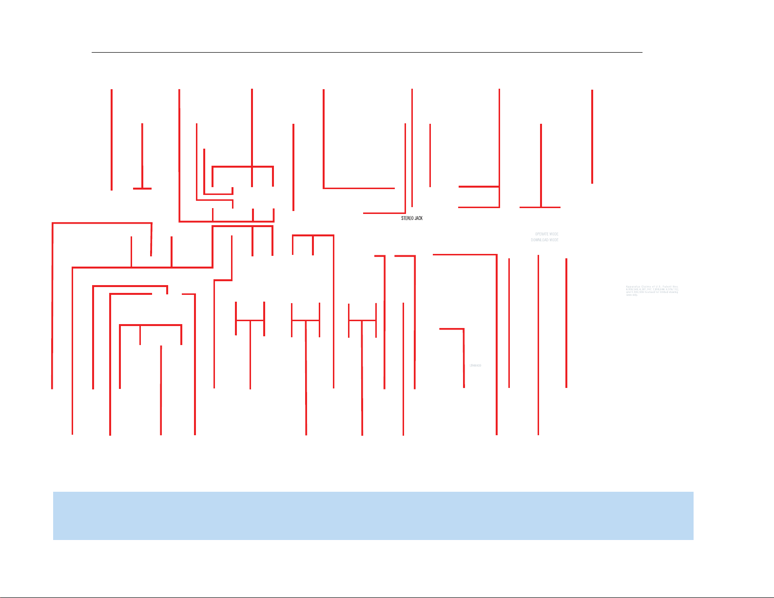
FM Antenna
XM
Antenna
AM Antenna
S-Video 2
Output
Composite 2
Output
Composite
1, 2 and 3
S-Video
1, 2 and 3
Video
Monitor
Outputs
HDMI
1, 2 and 3
AC Power
Cord
Component
1 and 2
Stereo Jack
HDMI
Monitor
Output
Component Video
Monitor Outputs
Subwoofer
Output
Preamp
Outputs
Front Speaker
Outputs
Surround
Speaker
Outputs
6-/8Channel
Inputs
Surround
Back/Zone 2
Speaker Outputs
Center Speaker
Outputs
Switched AC
Accessory
Outlet
RS-232
Reset
RS-232
Serial Port
Coaxial
Digital
Audio
Output
Coaxial
1 and 2
Digital
Audio
Optical 1 and 2
Digital Audio
Analog 1-5
Inputs
Zone 2
IR Input
Remote
IR Input
Remote
IR Output
Analog 2
Outputs
Analog 4
Outputs
RS-232
Mode
11
AVR254
harman/kardon
NOTE: To make it easier to follow the instructions throughout the manual that refer to this illustration, a copy of this page may be downloaded from the Product Support section at
www.harmankardon.com.All connectors are inputs except as indicated.
Page 12

12
AVR254
REMOTE CONTROL FUNCTIONS
The AVR 254 remote is capable of controlling 7devices,including the
AVR itself. During the installation process,you may program the codes
for each of your source components into the remote.Each time you
wish to use the codes for any component, first press its Selector button.
This changes the button functions to the appropriate codes.
Each Source Selector has been preprogrammed to control certain types
of components,with only the codes specific to each brand and model
changing,depending on which product code is programmed. The AUX
Source Selector may be used for any of five device types: a CD player,
an HDTV set-top box, a PVD recorder used with cable or satellite television, a TiVO
on the product code programmed into the AUX Source Selector as
described in the Initial Setup section. CD players use codes beginning
with a 0, 1 or 2;VCRs use codes beginning with a 3 or 4; HDTV
set-top boxes use codes beginning with a 6; PVDs use codes beginning
with a 7 and TiVO set-top boxes use codes beginning with an 8.
The remote automatically switches to the correct device mode,and
it will operate the device as described in the function list in Table A13
in the appendix.
Similarly, the CBL/SAT Source Selector automatically selects cable or
satellite television operation depending on the first digit of the product
code: 0, 1 or 2 for cable and 3 or 4 for satellite boxes.
Most of the buttons on the remote have dedicated functions,although the
precise codes transmitted will vary depending on which source device
has been selected for operation. Due to the wide variety of functions
unique to various source devices,we have included only a few of the mostoften used functions on the remote,including alphanumeric keys,transport
controls,television-channel control, menu access and power on and off.
Please refer to the descriptions below for more specific information.
Some buttons are only used to operate the AVR, and their functions are
available at any time,even if the remote has been switched to another
device’s mode:AVR Power On and Off, Audio Effects,Video Modes,
Surround Modes,Volume and Mute. Press the AVR Settings button near
the bottom of the remote to return it to AVR mode.
Any given button may have different functions,depending on which
component is being controlled. Some buttons are labeled with these
functions.For example,the Page Up/Down Buttons are labeled for use
as Channel Up/Down Buttons when controlling a television or cable box.
See Table A13 in the appendix for listings of the different functions for
each type of component.
®
set-top box or a VCR.The device mode will depend
IMPORTANT NOTE: All of the AVR 254’s audio and video
inputs are independently assignable.As explained in the Initial
Setup section, it is necessary to set up each source,which
includes selecting the inputs to which the device is physically
connected.Any device may be connected to any compatible
input and given any name (e.g. DVD or Game).The Source
Selectors’ device types may be changed. For example, the TV
Source Selector may be reprogrammed to operate a DVD player.
IR Transmitter Lens: As buttons are pressed on the remote,
infrared codes are emitted through this lens.Make sure it is pointing
toward the component being operated.
AVR Power On Button:Press this button to turn on the AVR. The
Master Power Switch on the AVR 254’s front panel must first have been
switched on.
Device Power Off Button:When the remote has been switched to
a device’s mode by pressing its Source Selector, press this button to
turn off the device.
Device Power On Button:When the remote has been switched
to a device’s mode by pressing its Source Selector, press this button to
turn on the device.
Mute Button: Press this button to mute the AVR 254’s speaker and
headphone outputs temporarily. To end the muting,press this button
or adjust the volume.Muting is also canceled when the receiver is
turned off.
AVR Power Off Button:Press this button to turn off the AVR 254.
Source Selectors: Press one of these buttons to select a source
device,which is a component where a playback signal originates,e.g.,
DVD, CD,cable TV, satellite or HDTV tuner.This will also turn on the
receiver and switch the remote’s mode to operate the source device.
The first press of the Radio Selector switches the AVR to the last-used
tuner band (AM, FM or XM). Each successive press changes the band.
Audio Effects: This button is only used to operate the AVR.Press it
to directly access the Audio Effects submenu,which allows adjustment
of the tone and other controls.Each successive press scrolls to the next
line in the menu. See the Initial Setup section for more information.
Video Modes: This button is only used to operate the AVR.Press it
for direct access to the Video Modes submenu,which contains settings
that may be used to improve the picture if necessary after you have
adjusted the picture settings using the video display or TV. Each successive press scrolls to the next line in the menu. See the Advanced
Functions section for more information.
Surround Modes: This button is only used to operate the AVR.Press
it to directly access the Surround Modes submenu. Each successive
press scrolls to the next line in the menu, or use the
to scroll to the next line:Auto Select, Virtual Surround, Stereo,Movie,
Music or Video Game. Each menu line represents a type of audio signal,
and is set to the preferred surround mode that you manually select.
Press the OK Button when the menu line is highlighted, and the available
surround mode options for the current signal will appear. Use the
Buttons to select the desired mode,and press the OK Button to engage
it. Press the Back/Exit Button to exit the Surround Modes menu and
display the next higher menu in the hierarchy.
See the Advanced Functions section for more information on surround
modes.
Sleep Settings Button: Press this button to activate the sleep timer,
which turns off the receiver after a programmed period of time of up to
90 minutes.Each successive press increases the timer by 10 minutes,
ending with the “Sleep Off”message.
harman/kardon
⁄/¤
Buttons
⁄/¤
Page 13

AVR Power Off
AVR Power On
Source Selectors
Audio Effects
Alphanumeric Keys
Teletext
Volume
Mute
Device Power On
Device Power Off
Surround Modes
Video Modes
OK
Navigation
Activity
Menu
Disc Menu
Channel
Sleep Settings
Transport Controls
Source Settings
IR T ransmitter Lens
Last
Back/Exit
Record
Info Settings
AVR Settings
Zone Selector
13
AVR254
harman/kardon
15
NOTE: To make it easier to follow the
instructions throughout the manual that refer
to this illustration, a copy of this page may
be downloaded from the Product Support
section at www.harmankardon.com.
Page 14

14
AVR254
REMOTE CONTROL FUNCTIONS
Volume Control:Press this button to raise or lower the volume.
Navigation (
used to make selections within the menu system.These buttons are
also used to operate the tuner.
Alphanumeric Keys: Use these buttons to enter numbers for
radio station frequencies or to select station presets.Use the alphabetic
keys with other products as required.When prompted for a text entry,
the first press of the key displays the first letter printed above the key.
Each additional press displays the other letters.When the desired letter
appears,wait a moment for it to be entered before moving to the next
character.
⁄/¤
›
/‹/
) and OK Buttons: These buttons are
Zone Selector: Use this switch to select whether AVR commands
will affect the main listening area (Zone 1) or the remote zone of a
multizone system (Zone 2). For normal operation, leave the switch in
the Zone 1 position.
Track Skip: These buttons have no effect on the receiver, but are
used with source components to change tracks or chapters.
Transport Controls: These buttons have no effect on the receiver,
but are used to control many source components.
Last Channel:When controlling a cable,satellite or HDTV set-top
box or a TV, press this button to return to the previous television channel.
Activity:This button may be programmed to transmit a series of
commands with a single press,which is useful for powering on all
devices and selecting the correct settings on each device,or for selecting
multi-digit channels with a single press.See the Advanced Functions
section for more information on Activities.
harman/kardon
Back/Exit: Press this button to return to the previous menu or to exit
the menu system.This button may have the same effect with some
source devices.
Menu Button:This button is used to display the main menu on some
source devices.To display the AVR 254’s main menu, press the AVR
Settings Button.
Disc Menu:While a DVD is playing,press the DVD Source Selector,
then this button, to display the disc’s menu.
Teletext Buttons: Use these buttons with a Teletext-capable televi-
sion if your broadcast, cable or satellite provider offers Teletext ser vice.
They are normally not used in North America.These buttons are also
used to operate some source devices.See Table A13 in the appendix
for details.
Channel/Page Control:When the tuner has been selected,this
control selects a preset radio station. Press these buttons while operating a cable,satellite or HDTV set-top box or a television to change
channels.The Page control may be available with some DVD players
when playing a DVD Audio disc containing pages of images associated
with a track.
Record Button: Use this button to make recordings when an audio
or video recorder is in use.
AVR Settings Button:Press this button to display the AVR’s Main
Menu. It is also used to switch the remote’s device mode from a source
device to the AVR.
Info Settings Button: Press this button to display the AVR’s Info
Menu, which contains the settings for the current source.
Source Settings Button: Press a Source Selector and then this
button to display a source device’s settings menu.
Page 15
SubwooferPreout
12 3
15
AVR254
CONNECTIONS
There are different types of audio and video connections used to
connect the receiver to the speakers and video display, and to connect
the source devices to the receiver.To make it easier to keep them all
straight, the Consumer Electronics Association (CEA
a color-coding standard. See Table 1.
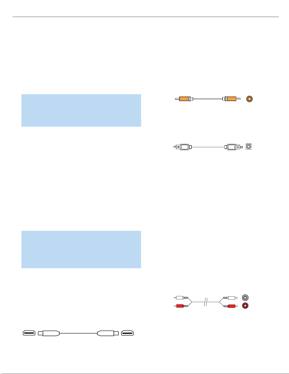
Table 1– Connection Color Guide
Audio Connections
Left Right
Front (FL/FR)
Center (C)
Surround (SL/SR)
Surround Back (SBL/SBR)
Subwoofer (SUB)
Digital Audio Connections
Coaxial
Optical
Video Connections
Component Y Pb Pr
Composite
S-Video
HDMI™ Connections (digital audio/video)
HDMI
Input
®
) has established
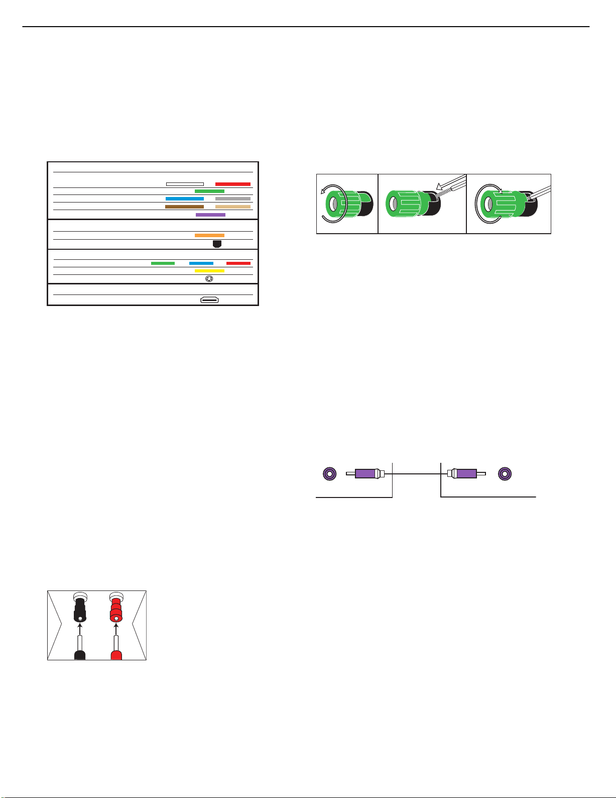
Bare wire cables are installed as follows (see Figure 2):
1. Unscrew the terminal cap until the pass-through hole in the collar is
revealed.
2. Insert the bare end of the wire into the hole.
3. Hand-tighten the cap until the wire is held snugly.
Figure 2 – Binding-Post Speaker Terminals With Bare Wires
Subwoofer
The subwoofer is a specialized type of loudspeaker used to play only
the low frequencies (bass), which require much more power than the
other speaker channels.In order to obtain the best results,most speaker
Types of Connections
This section will briefly review different types of cables and connections.
Speaker Connections
Speaker cables carry an amplified signal from the receiver’s speaker
terminals to each loudspeaker. Speaker cables contain two wire conductors,or leads,inside plastic insulation. The two conductors are usually
differentiated in some way, by using different colors,or stripes, or by
adding a ridge to the insulation. Sometimes the wires are different,
colors e.g. copper-colored and silver.
manufacturers offer powered subwoofers,in which the speaker contains
its own amplifier on board. Usually, a line-level (nonamplified) connection
is made from the receiver’s Subwoofer Output to a corresponding jack
on the subwoofer, as shown in Figure 3, but sometimes the subwoofer
is connected to the receiver using the front left and right speaker outputs,
as with passive in-wall subwoofers,and then the front left and right
speakers are connected to terminals on the subwoofer.
Although the subwoofer output looks similar to the analog audio jacks
used for the various components,it is filtered and only allows the low
frequencies to pass.Don’t connect this output to any other devices.
Although doing so won’t cause any harm, performance will suffer.
The differentiation is important because each speaker must be connected
to the receiver’s speaker-output terminals using two wires,one positive
(+) and one negative (–), referred to as speaker polarity. It’s important
to maintain the proper polarity for all speakers in the system, or performance can suffer, especially for the low frequencies.
Figure 3 – Subwoofer
harman/kardon
Always connect the positive terminal on the loudspeaker, which is usually
colored red, to the positive terminal on the receiver, which is colored as
shown in the Connection Color Guide (Table 1). Similarly, always connect
the black negative terminal on the speaker to the black negative terminal
on the receiver.
The AVR 254 uses binding-post speaker
terminals that can accept banana plugs
+
or bare-wire cables.Banana plugs are
simply plugged into the hole in the middle
of the terminal cap.See Figure 1.
Figure 1 – Binding-Post Speaker Terminals With Banana Plugs
Connecting Source Devices to the AVR
The AVR 254 is designed to process audio and video input signals,
playing back the audio and displaying the video on a television or
monitor connected to the AVR. These signals originate in what are
known as “source devices,”including your DVD player,CD player,DVR
(digital video recorder) or other recorder, tape deck, game console,
cable or satellite television box or MP3 player.Although the tuner is
built into the AVR, it also counts as a source,even though no external
connections are needed, other than the FM and AM antennas and the
XM antenna module.
Separate connections are required for the audio and video portions of
the signal, except for digital HDMI connections.The types of connections
used depend upon what’s available on the source device, and for video
signals,the capabilities of your video display.
18
Page 16
Coaxial
Coaxial digital
audio cable
16
AVR254
CONNECTIONS
Audio Connections
There are two formats for audio connections: digital and analog.Digital
audio signals are required for listening to sources encoded with digital
surround modes,such as Dolby Digital and DTS,or for non-compressed
PCM digital audio.There are three types of digital audio connections:
HDMI, coaxial and optical.Any type of digital audio connection may be
used for each source device,but never more than one for the same
source.However, it’s okay to make both analog and digital audio connections to the same source.
If your video display or source device is not HDMI-capable,use one of
the analog video connections (composite,S- or component video) and,
if available on your source device,either a coaxial or optical digital audio
connection.
Coaxial digital audio jacks are usually color-coded in orange.Although
they look similar to analog jacks,they should not be confused, and you
should not connect coaxial digital audio outputs to analog inputs or
vice versa. See Figure 5.
NOTE: Since HDMI signals may carry both audio and video, if
your video display device has an HDMI input, make a single HDMI
Figure 5 – Coaxial Digital Audio
connection from your source device (such as a DVD player) to
the AVR. No separate digital audio connection is usually required.
Make sure to turn the volume on your television all the way down.
Optical digital audio connectors are normally covered by a shutter to
protect them from dust.The shutter opens as the cable is inserted.Input
connectors are color-coded using a black shutter, while outputs use a
Digital Audio
gray shutter. See Figure 6.
harman/kardon
The AVR 254 is equipped with three HDMI (High-Definition Multimedia
Interface) inputs,and one output. HDMI technology enables digital audio
and video information to be carried using a single cable,thus delivering
the highest quality picture and sound.
There are different HDMI versions,depending on the capability of
the source device and the type of signal it is capable of transmitting.
In addition, receivers and processors such as the AVR 254 may handle
the incoming signal in several different ways,depending on their capability
as well.The AVR 254 uses HDMI version 1.3a,and is capable of
processing both the audio and video components of the HDMI data,
minimizing the number of cable connections in your system.Thanks to
the higher bandwidth and speed of HDMI version 1.3a, the AVR 254
implements Deep Color, which increases by an order of magnitude the
shades of color that can be displayed; and the latest lossless multichannel
audio formats,including Dolby TrueHD and DTS-HD Master Audio.
NOTE: Some DVD-Audio,SACD,HD-DVD and Blu-ray Disc
players,output mulitchannel audio only through the source’s
multichannel analog outputs.For those devices,make a separate analog audio connection in addition to the HDMI connection, which is still used for video and to listen to Dolby Digital,
DTS or PCM materials that may be stored on the disc.
In addition, the AVR 254 will convert analog video signals to the HDMI
format, upscaling to high-definition 1080p resolution.You may view the
AVR 254’s own on-screen display menus using the HDMI output.
The physical HDMI connection is simple.The connector is shaped for
easy plug-in (see Figure 4). If your video display has a DVI input and is
HDCP-compliant, you may use an HDMI-to-DVI adapter (not included)
to connect it to the AVR’s HDMI Output, but a separate audio connection
is required. HDMI cable runs are usually limited to about 10 feet,
depending on the type of cable used.
Figure 4 – HDMI Connection
Optical digital
audio cable
Figure 6 – Optical Digital Audio
Optical
Analog Audio
Analog connections require two cables,one for the left channel (white)
and one for the right channel (red).These two cables are often attached
to each other for most of their length. See Figure 7.
Most sources that have digital audio jacks also have analog audio jacks,
although some older types of sources,such as tape decks,only have
analog jacks.For sources that are capable of both digital and analog
audio,you may make both connections.
The analog audio connection is strongly recommended if you intend to
use the source with the multizone system. It’s required if you will be
using the multizone preamp outputs with an external amplifier to power
your remote speakers,as the AVR 254’s multizone system is not capa-
ble of converting the digital signal to analog format. It’s suggested that
you also use the analog audio connections when using the Surround
Back/Zone 2 speaker outputs,in case another two-channel digital audio
source is in use in the main listening area.The AVR 254 is only capable
of processing one PCM source at a time.
You may only record materials from DVDs or other copy-protected
sources,using analog connections.Remember to comply with all copy-
right laws,if you choose to make a copy for your own personal use.
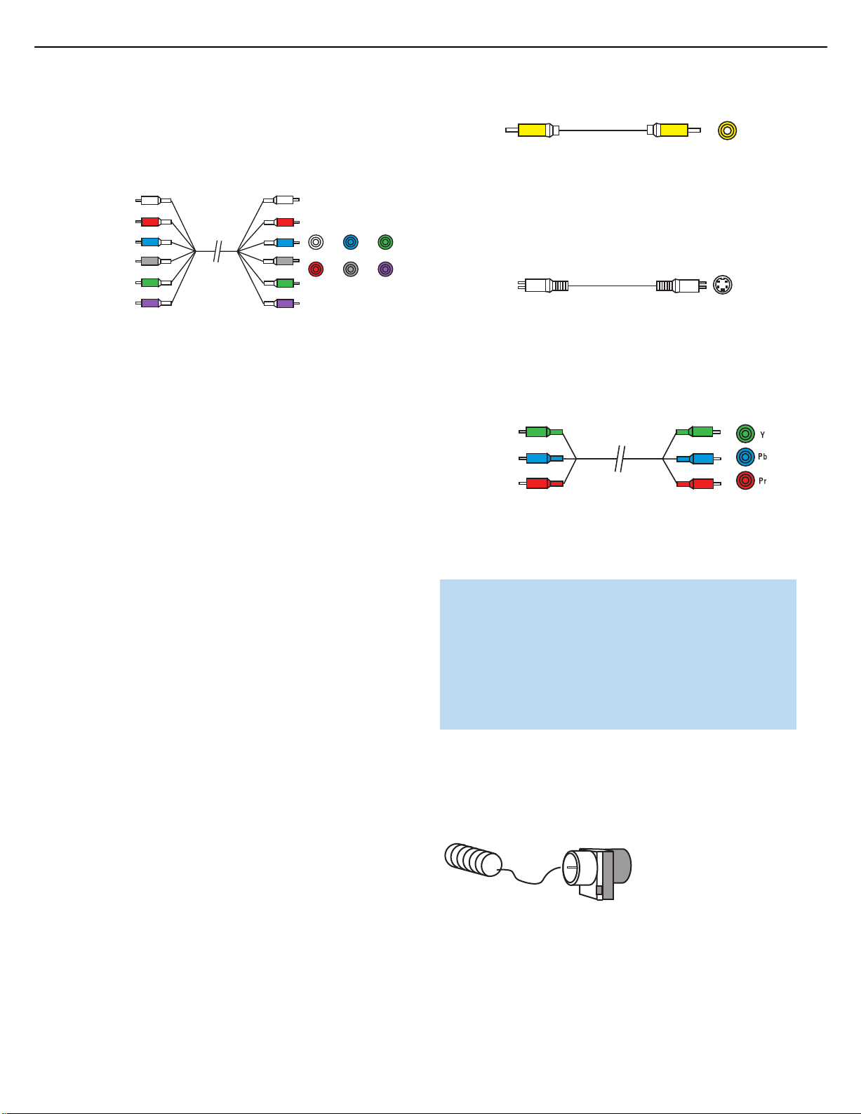
Analog audio
cable (RCA)
Figure 7 – Analog Audio
L
R
Multichannel analog connections are used with some high-definition
sources where the copy-protected digital content is decoded inside the
source.These types of connections are usually used with DVD-Audio,
SACD, Blu-ray Disc,HD-DVD and other multichannel players. See
Figure 8. However, the multichannel analog audio connection is not
19
Page 17
S-video cable
Composite
video cable
17
AVR254
CONNECTIONS
required for DVD-Audio players compliant with HDMI version 1.1 or
better, or HD-DVD and Blu-ray Disc players that decode the digital audio
internally and output linear PCM signals in digital format. Consult the
owner’s guide for your disc player for more information.
Multichannel
analog audio
cable (RCA)
Figure 8 – Multichannel Analog Audio
Front Surround Center
Subwoofer
Figure 10 – Composite Video
S-video,or “separate” video, transmits the chrominance and luminance
components using separate wires contained within a single cable.The
plug on an S-video cable contains four metal pins,plus a plastic guide
pin. Be careful to line up the plug correctly when you insert it into the
jack on the receiver, source or video display. See Figure 11.
Figure 11 – S-Video
Component video separates the video signal into three components –
The AVR 254 also offers an analog audio input on the rear panel in the
form of a stereo 1/8" mini jack. Connect the headphone output of any
audio source,such as an MP3 player or portable CD player, to the
Stereo Jack input. See Figure 9.
one luminance (“Y”) and two sub-sampled color signals (“Pb” and “Pr”) –
that are transmitted using three separate cables.The “Y”cable is color-
coded green, the “Pb”cable is colored blue and the “Pr” cable is
colored red. See Figure 12.
harman/kardon
Figure 9 – Stereo Jack
Video Connections
Although some sources only produce an audio signal (e.g., CD player,
tape deck), many sources output both audio and video signals (e.g.,
DVD player, cable television box, HDTV tuner, satellite box,VCR, DVR).
In addition to the audio connection, make one type of video connection
for each of these sources (only one at a time for any source).
Digital Video
If you have already connected a source device to one of the HDMI
inputs as explained in the Digital Audio Connections section,you have
automatically made a video connection at the same time,as the HDMI
signal includes both digital audio and video components.
If the source device is not capable of transmitting its digital audio signal
through the HDMI connection, use one of the coaxial or optical digital
audio inputs for the source.
If a multichannel analog audio connection is required for certain lossless
formats (e.g., DVD-Audio,SACD,HD-DVD or Blu-ray Disc), you may
make both audio connections.To listen to the multichannel disc, set the
Audio Auto Polling setting to the 6/8CH inputs,and the AVR will automatically select it when no digital signal is output by the player.
Component
video cable
Figure 12 – Component Video
If it’s available on your video display, an HDMI connection is recom-
mended as the best quality connection, followed by component video,
S-video and then composite video.
NOTES:
• Copy-protected sources are not available at the Component
Video Monitor Outputs.
• Standard and high-definition analog video signals are
upscaled to 1080i resolution for the Component Video
Monitor Outputs.For improved video performance,consider
upgrading to an HDMI-capable video display with 1080p
resolution.
Antennas
The AVR 254 uses separate terminals for the included FM and AM
antennas that provide proper reception for the tuner.
The FM antenna uses a 75-ohm F-connector. See Figure 13.
Analog Video
There are three types of analog video connections: composite video,
S-video and component video.
Composite video is the basic connection most commonly available.The
jack is usually color-coded yellow,and looks like an analog audio jack,
although it is important never to confuse the two.Do not plug a composite
video cable into an analog or coaxial digital audio jack, or vice versa.
Both the chrominance (color) and luminance (intensity) components of
the video signal are transmitted using a single cable.See Figure 10.
Figure 13 – FM Antenna
The AM loop antenna needs to be assembled.Connect the two leads
to the spring terminals on the receiver.As AM antenna leads have no
polarity, it doesn’t matter which of the two terminals is used for either
lead. See Figure 14.
20
Page 18

18
AVR254
CONNECTIONS
Figure 14 – AMAntenna
To enjoy XM satellite radio,purchase an XM antenna module designed
for use with XM Ready devices and a subscription to the XM service.
We recommend the XM Mini Tuner and Home Dock Bundle, available
at www.xmradio.com.The older Connect and Play module is also compatible with the AVR 254, but it may no longer be available in your area.
An XM Ready-compatible module uses the special connector on the
AVR 254’s rear panel that allows you to use the AVR’s tuner, including
its 40 preset station locations and remote control.Although you may
use a module with standard audio connections,which may be indicated
for “car and home use,”you will not be able to enjoy the AVR 254’s
ease of control.
harman/kardon
RS-232 Serial Port
The RS-232 serial port on the AVR 254 is used only for software
upgrades.If we release an upgrade for the receiver’s operating system
at some time in the future,it may be downloaded to the AVR using this
port. Complete instructions will be provided at that time.
Page 19
AVR 254
FM
AM
AVR 254
SR
SL
FR FL
SBR
SBL
C
19
AVR254
INSTALLATION
You are now ready to connect the various components to the receiver.
Before beginning,turn off all components, including the AVR 254,
unplug their power cords.
until you have finished making all of your connections.
Remember that the receiver generates heat while it is on. Select a
location that leaves several inches of space on all sides of the receiver.
Avoid completely enclosing the receiver inside an unventilated cabinet.
It is preferable to place components on separate shelves rather than
stacking them directly on top of the receiver. Some surface finishes are
Don’t plug in any of the power cords
delicate.Try to select a location with a sturdy surface finish.
and
AVR 254
SUB
Figure 18 – Subwoofer Connection
Step Three – Connect the Antennas
harman/kardon
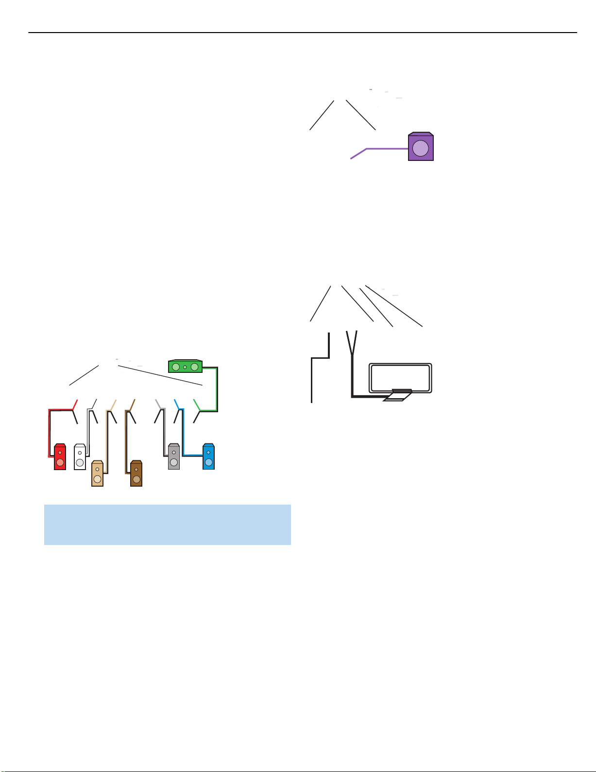
Step One – Connect the Speakers
If you have not yet done so,place your speakers in the listening room,
as described in the Speaker Placement section above.
Connect the center, front left, front right, surround left, surround
right, surround back left and surround back right loudspeakers to the
corresponding speaker terminals on the AVR 254. See Figure 17.
Maintain the proper polarity by always connecting the positive and
negative terminals on each speaker to the positive and negative
terminals on the receiver. Use the Connection Color Guide on page 18
as a reference.
Figure 17 – Speaker Connections
NOTE: If you only have one surround back speaker, wait until after
you have run the EzSet/EQ process in the Initial Setup section
before connecting it to the Surround Back Left speaker outputs.
Step Two – Connect the Subwoofer
Connect the Subwoofer Output on the AVR 254 to the line-level input
on your subwoofer. See Figure 18. Consult the manufacturer’s guide for
the subwoofer for additional information.
When the system has two subwoofers for a 7.2-channel system, use a
Y-Adapter (not included) with one male RCA plug and two female RCA
jacks.Connect the male plug to the Subwoofer Output, and connect
each female jack to a cable that is then plugged into the line-level input
on each subwoofer.
Connect the FM and AM antennas to their terminals. If you have
purchased an XM antenna module designed for connection to an
XM Ready device,connect it now.To enjoy XM Radio,remember to
purchase a subscription and activate your antenna module.More
information is available at www.xmradio.com. See Figure 19.
Figure 19 – Antenna Connections
Step Four – Connect the Source Components
A source is a device where the audio and video signals originate.Some
sources,such as CD players,only offer audio, while sources used for
watching movies or broadcast-television programming deliver a video
signal as well.
Referring to the photograph of the AVR 254 remote control on page 15,
there is a section of 7 buttons near the top of the remote designated
“Source Selectors”: Cable/Sat, DVD, Media Server, Radio,TV, Game
and AUX.Each of these buttons corresponds to a “source input”.The
AVR 254’s flexible design allows you to use almost any combination
of audio and video connections for each source device.The goal of
Step Four of the Installation is to match up each of your source devices,
e.g., DVD player and cable television box, with the correct connectors
on the AVR 254.
You may connect a source device to any appropriate input connectors.
Note which audio and video inputs are used for each device in Table A5
in the appendix.Table A2 indicates the default input-connection assignments,any of which may be changed to match the actual connections
in your system.
The precise connections to be made depend on the capabilities of the
source device and your video display (TV). Select the best audio and
video connections for each source.The types of connections are listed
in order of preference:
Page 20
AVR 254
AVR 254
AVR 254
20
AVR254
INSTALLATION
HDMI Connections
• Choose the HDMI connection if it’s available on your source device
and your TV. A HDMI connection carries both digital audio and video,
enabling a single-cable connection from the source device to the
AVR.Except as noted below, no other audio or video connections
are required.
NOTE: If your DVD-Audio,SACD,Blu-ray Disc or HD-DVD player
is not capable of outputting multichannel digital audio through its
HDMI output,make additional 6-/8-channel analog audio connections.
outputting the multichannel audio through its HDMI output, make the
following additional connections (see Figure 21):
• Connect the DVD player’s 6-/8-channel analog audio outputs to the
6-/8-Channel Analog Audio Inputs on the AVR.
Audio Connections (for non-HDMI sources)
• Choose one digital audio connection: Optical or Coaxial
• Optional, or where digital audio is not available:Analog audio for
making recordings for personal use or as a backup.Analog audio is
required for older analog sources that don’t have digital audio outputs,
such as cassette decks.
Video Connections (for non-HDMI sources)
(choose only one,and make sure that type is available on your TV)
• Component video • Composite video
• S-video
NOTES:
• If the video display is equipped with a DVI digital video input,
make sure it is also HDCP-compliant (High-Bandwidth Digital
Content Protection) to display copy-protected materials.
Figure 21 – Connecting a Multichannel Audio Player
Component Video: If the DVD player or the TV does not have an
HDMI connector, but they both have component video connectors,
connect the player as follows (see Figure 22):
• Connect the DVD player’s component video output to the Component
Video 1 or 2 Input on the AVR.
• Connect one of the DVD player’s digital audio outputs to one of the
Coaxial or Optical inputs on the AVR.
harman/kardon
• If the source or video display has a DVI input, use an HDMIto-DVI adapter (not included), and make separate audio
connections.
Connect a DVD, SACD, Blu-ray Disc or HD-DVD Player
HDMI Video:
connector, connect the player as follows (see Figure 20):
• Connect the DVD player’s HDMI output to the HDMI 1,2 or 3 Input on
the AVR.
Figure 20 – Connecting An HDMI-Equipped Disc Player
If the player is capable of playing multichannel discs,including DVDAudio,SACD,Blu-ray Disc and HD-DVD,but it is not capable of
If the DVD player and the TV both have an HDMI
Figure 22 – Connecting a Component-Video-Equipped Disc Player
If the player is capable of playing multichannel discs,including DVD-Audio,
SACD ,Blu-ray Disc and HD-DVD, make the following additional connection
(see Figure 21):
• Connect the DVD player’s 6-/8-channel analog audio outputs to the
6-/8-Channel Analog Audio Inputs on the AVR.
Composite/S-Video: If the best video connection common to both
the DVD player and the TV is either S-video or composite video, follow
these steps (see Figure 23):
• Connect the DVD player’s S-video or composite video output (use one
connection only) to the Video 1,2 or 3 Input on the AVR.You may also
use the Video 4 Composite or S-video Input located on the AVR’s front
panel (see Figure 31).
Page 21
AVR 254
AVR 254
AVR 254
21
AVR254
INSTALLATION
• Connect the DVD player’s digital audio output to one of the Coaxial or
Optical inputs on the AVR.
If the player is capable of playing multichannel discs,including DVD-Audio,
SACD, Blu-ray Disc and HD-DVD, make the following additional connection
(see Figure 23):
• Connect the DVD player’s 6-/8-channel analog audio outputs to the
6-/8-Channel Analog Audio Inputs on the AVR.
Figure 24 – Connecting an HDMI-Equipped Recorder
Component Video: If the recorder or the TV does not have an
HDMI connector, but they both have component video connectors,
connect the recorder as follows (see Figure 25):
• Connect the recorder’s component video output to the Component
Video 1 or 2 Input on the AVR. This connection is for playback only,
as the AVR cannot make recordings from component video sources.
harman/kardon
Figure 23 – Connecting a Composite- or S-Video-Equipped Disc Player
NOTES:
• Refer to Table A2 in the appendix for the default audio and
video input assignments for each source.Using the default
connections,if appropriate for your system, may save a few
steps during Initial Setup.However, thanks to the AVR 254’s
flexibility, you may assign any audio and any video input to
any source,as long as the assignments match the physical
connections.
• If you wish to make recordings from a DVD, use an S-video or
composite video input, and an Analog Audio input in addition
to any other connections.The AVR cannot make recordings
from HDMI or component video sources,and digital audio
sources may only be recorded in two channels.
Connect an Audio/Video Recorder (PVD,DVR or TiVo®)
HDMI Video:
connect the recorder as follows (see Figure 24):
• Connect the recorder’s HDMI output to the HDMI 1, 2 or 3 Input
on the AVR. This connection is for playback only, as the AVR cannot
make recordings from HDMI sources.
• To make recordings, follow the instructions below for Composite/
S-video recorders.
If the recorder and the TV both have an HDMI connector,
• Connect the recorder’s digital audio output to a Coaxial or Optical
Input on the AVR (if available).
• Follow the instructions in the Composite/S-Video section for making
connections required for recordings.
Figure 25 – Connecting a Component-Video-Equipped Recorder
Composite/S-Video: If the best video connection common to
both the recorder and the TV is either S-video or composite video, or
to make recordings,follow these steps,using only one type of video
connection throughout (see Figure 26):
• Connect the recorder’s S-video/composite video output to the
Video 2 S-Video/Composite Video Input on the AVR.
• Connect the recorder’s S-video/composite video input to the Video 2
S-Video/Composite Video Output on the AVR.
• Connect the recorder’s analog audio outputs to the Analog 4 Audio
Inputs on the AVR.
• Connect the recorder’s analog audio inputs to the Analog 4 Audio
Outputs on the AVR.
Page 22

AVR 254
AVR 254
AVR 254
22
AVR254
INSTALLATION
harman/kardon
Figure 26 – Connecting a Composite or S-Video Recorder
• To make two-channel digital audio recordings, connect the recorder’s
digital audio output to one of the Optical or Coaxial Inputs,and connect the AVR’s Coaxial Digital Audio Output to the recorder’s coaxial
input.The AVR will convert an optical digital audio input signal to the
proper format for recording via the Coaxial Digital Audio Output.See
Figure 26.
Connect a Cable TV, Sa tellite, HDTV or Other Set-Top
Box for Broadcast Television
NOTE: If the TV has a digital audio output, connect it to one of
the digital audio inputs.If you use a direct cable connection to
your TV, or an antenna connection with the TV’s internal tuner,
connect either the TV’s digital audio output (if available) or its analog
audio outputs to the AVR. See Step Five for infor mation on
connecting the receiver’s video monitor outputs to the television.
HDMI Video: If the set-top box and the TV both have an HDMI
connector, connect the set-top box as follows (see Figure 24):
• Connect the set-top’s HDMI output to the HDMI 1,2 or 3 Input
on the AVR.
Component Video: If the set-top box or the TV does not have an
HDMI connector, but they both have component video connectors,
connect the set-top box as follows (see Figure 25):
• Connect the set-top’s component video output to the Component
Video 1 or 2 Input on the AVR (if available).
• Connect the set-top’s digital audio output to one of the Coaxial or
Optical Inputs on the AVR (if available).
Composite S/Video: If the best video connection common to both
the set-top box and the TV is either S-video or composite video, follow
these steps (see Figure 27):
• Connect the set-top’s S-video or composite video output (use one
connection only) to the corresponding Video 1,2 or 3 Input on the AVR.
• Connect the set-top’s digital audio output to one of the Coaxial or
Optical Inputs on the AVR (if available). For fully analog set-top boxes,
connect the box’s analog audio outputs to the AVR’s Analog 1,2, 3,
4 or 5 Audio Inputs.
Figure 27 – Connecting a Composite- or S-Video-Equipped Set-Top Box
Connect a CD Player or Any Audio-Only Device
If the CD player or other component has a digital audio output, connect
it to any available digital audio input on the AVR. If not, connect the CD
player’s left and right analog audio outputs to the Analog 1 or 2 Audio
Inputs.No video connection is required, although the AVR will display
any signal at the video input assigned to the same source as the audio
inputs.See Figure 28.
Figure 28 – Connecting a CD or Audio-Only Source
NOTES:
• A turntable may only be connected to the AVR if it is equipped
with an internal phono preamp,or if you supply an external
phono preamp,available at some audio specialty stores or
through the Harman Kardon Parts Dept.You may then connect
it to any set of analog audio inputs.
• Although there is no official source on the AVR 254 named
CD, Phono or Audio, you may assign the audio device to an
available source,such as TV (if the Cable/Sat source is in use
for broadcast television), Game or AUX.See the Initial Setup
section for more details on source assignment.
Connect a Tape Deck or Any Audio-Only Recorder
If the recorder has digital audio inputs and outputs,connect either its
coaxial or optical digital audio output (not both) to the corresponding
available input on the AVR, and connect the AVR’s Coaxial Digital Audio
Output to the recorder’s coaxial digital audio input.
Page 23
AVR 254
AVR 254
AVR 254
AVR 254
23
AVR254
INSTALLATION
To make analog audio recordings,connect the recorder’s left and right
analog audio outputs to the Analog 2 Audio Inputs on the AVR,and the
recorder’s analog audio inputs to the AVR’s Analog 2 Audio Outputs.
No video connection is required, although the AVR will display any signal
at the video input assigned to the same source as the Analog 2 Audio
Inputs.See Figure 29.
Figure 31 – Connecting a Device to the Front-Panel Inputs
Audio Components:Connect audio-only devices,such as CD players,
to either the Coaxial or Optical Digital Audio Inputs, or the Analog Audio
Inputs (see Figure 31).
harman/kardon
Figure 29 – Connecting an Audio Recorder
Connect a Portable Audio Player
For audio-only playback from a portable CD player, cassette deck, MP3
player or other device equipped with a 1/8-inch headphone jack, use
a stereo 1/8-inch mini-plug interconnect (not included) to connect the
device’s headphone jack to the Stereo Jack on the AVR. Use the
device’s own controls to operate it.See Figure 30.
Figure 30 – Connecting a Portable Audio Player
Alternatively, use an interconnect with a stereo 1/8-inch mini-plug at
one end and two RCA plugs at the other end to connect the player to
the Audio Inputs on the AVR’s front panel.See Figure 31.
Connecting a Game Console, Camera or Other Device
NOTE: If your video devices are equipped with HDMI or com-
ponent video outputs,you may connect them to any available
audio and video input on the AVR.
Step Five – Connect the Video Display
IMPORTANT NOTE: Do not connect any video output on the
video display (TV) to any video input on the AVR. Doing so will
cause undesirable video interference.
HDMI Video: If the display has an HDMI input, connect the HDMI
Monitor Output to the display (see Figure 32).Thanks to the AVR 254’s
sophisticated video processing and upscaling capabilities,no other video
connections are required from the AVR to the video display.Analog
video sources (composite,S-video and component) are converted to
the HDMI format and upscaled to as much as 1080p resolution,
depending on the display’s capabilities. Proceed to Step Six.
If a device will only be connected temporarily, you may use the audio/
video inputs on the front panel.When not in use, place the supplied
covers over the jacks for a cleaner appearance by snapping the covers
in place.To remove the covers,gently press on the left side of each
cover so that it pivots out.
Video Components: Install video components,e.g.,game consoles
and camcorders,as follows (see Figure 31):
• Connect the component’s S-video or composite video output (use
only one connection) to the corresponding front-panel Input on the AVR.
• Connect the component’s optical or coaxial digital audio output to
either the Optical or Coaxial Input on the front panel (if available).
For fully analog devices, connect the device’s analog audio outputs
to the AVR’s front-panel Analog Audio Inputs.
Figure 32 – HDMI Monitor Output
Component Video: If the display does not have HDMI inputs,but
does have component video inputs,connect the Component Video
Monitor Outputs to the display (see Figure 33).As with HDMI connections,the AVR 254 is capable of converting composite and S-video
sources to the component video format, while upscaling the resolution to
as high as 1080i, depending on the display’s capabilities. Unlike HDMI
connections,component video connections do not enable the AVR 254
to detect the display’s capabilities and the appropriate resolution must
be selected manually, as described in the Initial Setup section.
Page 24

AVR 254
AVR 254
AVR 254
24
AVR254
INSTALLATION
Step Seven – Insert Batteries in Remote
The AVR 254 remote control uses four AAA batteries, which are included.
To remove the battery cover located on the back of the remote,
squeeze the tab and lift the cover.
Figure 33 – Component Video Monitor Outputs
Insert the batteries,as shown in Figure 36, making sure to observe
the correct polarity.
Composite/S-Video: If the video display does not have HDMI or
component video inputs,connect the corresponding composite or
S-video Monitor Output to the display. If available,S-video is preferred
over composite video,and if used, the AVR 254 will convert composite
video sources to S-video.See Figure 34.
Figure 36 – Remote Battery Compartment
harman/kardon
Figure 34 – Composite and S-Video Monitor Outputs
Consult the manual for your TV to make sure you understand how
to select the correct video input.
Step Six – Plug in AC Power
Having made all of your wiring connections,it is now time to plug each
component’s AC power cord into a working outlet.
You may plug one device into the AC Switched Accessory Outlet on the
rear of the AVR 254. See Figure 35. Make sure this device draws no
more than 50 watts.The device should have its mechanical or master
power switch turned on, and it will power on any time the AVR 254 is
turned on. If the device has a clock or must always be on, do not plug
it into this outlet.
When using the remote,remember to point the lens toward the front
panel of the AVR 254. Make sure no objects,such as furniture, are
blocking the remote’s path to the receiver. Bright lights, fluorescent lights
and plasma video displays may interfere with the remote’s functioning.
The remote has a range of about 20 feet, depending on the lighting
conditions.It may be used at an angle of up to 30 degrees to either
side of the AVR.
If the remote seems to operate intermittently, or if pressing a button
on the remote does not cause the AVR Settings Button or one of the
Source Selectors to light up,then make sure the batteries have been
inserted correctly, or replace all three batteries with fresh ones.
Step Eight – Program Sources Into the Remote
The AVR 254 remote not only is capable of controlling the receiver,
but it may also be programmed to control many brands and models
of DVD players,cable boxes,satellite receivers, the Harman Kardon
DMC 1000 digital media center and TVs.
It may help to think of the remote as a book with pages.Each “page”
represents the button functions for a different device.In order to access
the functions for a particular device,first turn to its page; that is,switch
the remote’s device mode. This is done by pressing the AVR Settings
Button to access the codes that control the receiver, or the Source
Selector Buttons to access the codes for the devices programmed into
the remote.
Figure 35 – Switched ACAccessory Outlet
Before plugging the AVR 254’s AC Power Cord into an electrical outlet,
make sure that the Master Power Switch on the front panel is popped
out so that the word OFF appears on its top.Gently press the button to
turn the switch off.This will prevent the possibility of damaging the AVR
in case of a transient power surge.
The AVR 254’s remote is factory-programmed to control many Harman
Kardon DVD players.If you have other source devices in your system,
follow these steps to program the correct codes into the remote.
1. Using the codes in Tables A14–A24 of the Appendix,look up the
product type (e.g., DVD, cable TV box) and the brand name of your
source.The number(s) listed is/are potential candidates for the
correct code set for your particular device.
NOTE: The AUX Source Selector is used for the CD, HDTV,PVD
recorder,TIVO and VCR device types.Select the brand code
Page 25

AVR 254
25
AVR254
INSTALLATION
from the appendix table corresponding to the device and program it into the AUX Source Selector. Similarly,the CBL/SAT
Source Selector is used for either a cable or satellite television
set-top box.The first digit of the product code indicates the
device type.
2.Turn on your source device.
3.This step places the remote in program mode.Refer to Figure 37.
Press and hold the Source Selector.The button will tur n red, then go
dark. Continue holding it, and when it turns red again, release the
button; the remote is now in program mode.Follow the directions in
Step 4, below.
If you are unable to locate a code set that correctly operates your
source device,it will not be possible to use the AVR remote to control
that device.However, you may still connect the source to the AVR 254
and operate it using the device’s original remote control.
Most of the button labels on the remote describe the button’s function
when used to control the AVR 254. However, the button may perform
a very different function when used to control another device.Refer to
the Remote Control Function List,Table A13 in the Appendix, for a list of
each button’s functions with the various product types.
If you wish, you may program Activities, which are preprogrammed code
sequences that execute many code commands with a single button
press.You may also program “punch-through” codes, which allow the
remote to operate the channel or transport controls of another device
without having to switch the remote’s device mode. See page 53 for
instructions on these advanced programming functions.
harman/kardon
Figure 37 – Source Selectors
Optional: To reassign a device type from one Source Selector to another
Source Selector not being used, e.g. if there are two DVD players in the
system, press the Source Selector for the new device type now.For
example,to reassign the Cable/Sat Source Selector to operate a DVD
player, first press and hold the Cable/Sat Button, and then press the
DVD Button.
4. Enter a code from Step 1, above.
a) If the device turns off, press the Source Selector again to accept
the code; it will flash.The remote will exit Program mode.
b) If the device does not turn off, try entering another code.If you
run out of codes,you may search through all of the codes in the
⁄
¤
remote’s library for that product type by pressing the
Button repeatedly until the device turns off.When the device turns
off, enter the code by pressing the Source Selector, which will
flash.The remote then exits Program mode.
5. Once you have programmed a code, it’s a good idea to try using
some other functions to control the device.Sometimes,manufacturers
use the same Power code for several different models, while other
codes will vary.You may wish to repeat this process until you’ve
programmed a satisfactory code set that operates most of the
functions you frequently use.
6. Find out which code number you have programmed by pressing
and holding the Source Selector to enter the Program mode.Then
press the OK Button, and the Source Selector will flash in the code
sequence.One flash represents “1”,two flashes for “2”, and so forth.
A series of many fast flashes represents “0”.Record the codes programmed for each device in Table A9 in the appendix.
or
Step Nine – Remote IR Inputs and Output (Optional)
The AVR 254 is equipped with a Remote IR Input, a Zone 2 Input and
a Remote IR Output to facilitate use of your system with a remote control
in a variety of situations.See Figure 38.
Figure 38 – IR Inputs and Outputs
When the AVR 254 is placed in such a way that aiming the remote at the
front-panel IR sensor is difficult,such as inside a cabinet or facing away from
the listener, you may connect an external IR receiver, such as the optional
Harman Kardon HE 1000, to the Remote IR Input jack.When you are using
the AVR 254 in multizone mode,you may connect an optional IR receiver,
keypad or other control device to the Zone 2 IR Input for remote control
of the AVR 254 (and any sources connected to the AVR’s Remote IR
Output) from the remote zone.Any signals transmitted through the Zone 2
IR Input will only control source selection and volume for the remote zone.
If a source device is being shared with the main listening area, then any
control commands issued to that source will also affect the main room.
If any of your source devices are equipped with a compatible Remote
IR Input, use a 1/8" mini-plug interconnect cable (not included) to connect the AVR’s Remote IR Output to the source device’s Remote IR
Input, which will pass any applicable remote signals transmitted through
the AVR to the source device.This enables you to control your sources
even when the AVR itself is controlled via an external IR receiver.
Check with the manufacturer of the source device for more information
on the type of IR signal expected.The AVR 254 will output a “stripped
carrier” IR signal through the Remote IR Output.
Page 26

AVR 254
AVR 254
26
AVR254
INSTALLATION
To control more than one source device using the Remote IR Output,
connect all sources in “daisy chain”fashion, with the AVR’s Remote
IR Output connected to the first device’s Remote IR Input,the second
device’s Remote IR Output connected to the next device’s Remote
IR Input, and so forth.
Step Ten – Install a Multizone System (Optional)
The AVR 254 offers several methods of distributing music to other
listening areas in your home.A multizone system is not required to enjoy
the home theater experience.If you prefer not to install a multizone
system at this time,skip to Step Eleven to turn on the AVR 254 and
configure it.
IMPORTANT SAFETY NOTE: Installing a multizone system typically requires running various cables inside walls.Always comply
with the appropriate safety codes when installing concealed wiring.
The AVR 254’s multizone connections should be installed per the
requirements of all applicable state and local building codes,as
well as NEC (National Electrical Code) requirements.Failure to do
so may present a potential safety hazard. If you have any doubt
about your ability to work with electrical and telecommunications
wiring,you are advised to hire a licensed electrician or custom
installer to install the multizone system.
Multizone operation uses the Surround Back/Zone 2 amplifier channels,
whether you connect the remote speakers directly to the speaker outputs,or if you connect an optional external amplifier to the preamp outputs.This limits the system in the main listening room to 5.1 channels,
which means you cannot listen to 6.1- or 7.1-channel programs in the
main room.
Select one or both:
1. Connect the remote room’s speakers directly to the Surround
Back/Zone 2 Speaker Outputs.See Figure 39.
Figure 40 – Surround Back/Multiroom Preamp Outputs
This method requires you to provide an additional component: the
amplifier. However, this method may be used to increase the number
of remote rooms in the system when you are also using the Surround
Back/Zone 2 Speaker Outputs.
Place the amplifier in the same room as the AVR 254 so that a shorter
length of interconnect cable is used with a long run of speaker wire to
the remote room.This is better than placing the amplifier in the remote
room, which necessitates a long run of interconnect cable that would
then be subject to signal degradation.
In addition to the audio signal, you may connect an IR control device to
the AVR 254’s Zone IR Input so that listeners in the remote room may
turn the multizone system on or off, select a source input, control the
source device connected to that input and adjust the volume in the
remote zone.
NOTE: Only analog audio sources are available to the multizone
system.
Step Eleven – Turn On the AVR 254
Two steps are required the first time you turn on the AVR 254.
1. Gently press the Master Power Switch until the word OFF is no longer
visible.The Power Indicator above the two power switches should
light up in amber, indicating that the AVR is in Standby mode and is
ready to be turned on. See Figure 41. Normally, you may leave the
Master Power Switch in the ON position,even when the receiver is
not being used.
harman/kardon
Figure 39 – Surround Back/Zone 2 Speaker Outputs
If you prefer not to purchase an external amplifier to power a pair of
remote speakers,you may reassign the AVR 254’s Surround Back
amplifier channels to power the speakers.
2. Connect an external amplifier to the Surround Back/Multiroom
Preamp Outputs.See Figure 40.
Figure 41 – Power Switches
2.There are several ways in which the AVR 254 may be turned on from
Standby mode.
a) Press the Standby/On Switch on the front panel. See Figure 41.
b) Using the remote,press the AVR Power On Button or any of the
Source Selectors.See Figure 42.
Page 27

27
AVR254
INSTALLATION
Figure 42 – AVR Power On and Source Selectors
NOTES:
• Any time you press one of the Source Selectors on the
remote (i.e.,Cable/Sat, DVD,Media Server,Radio,TV, Game
or AUX),the remote will switch modes to transmit the codes
programmed to operate that device.To control the receiver,
press the AVR Settings Button to return the remote to AVR
mode.Some AVR functions are available in all device modes,
and you don’t have to press the AVR Settings Button first to
use them:Volume Controls (including Mute),Audio Effects,
Video Modes,Surround Modes,AVR Settings, Info Settings,
Sleep Settings and AVR Power On and Off.
harman/kardon
• If you are not using the AVR’s HDMI Output with your display,
you may not see a picture the first time you turn on the AVR 254,
or after a system reset.To correct this, press the front-panel
Resolution Button to display the current video output resolution.
⁄
Use the
patible with all video displays,then press the OK Button to
select the new setting.You will be prompted to accept or cancel the change; the CANCEL message will appear on the front
panel. Press the
then press the OK Button to complete the change to the output
resolution. Follow the directions in the Initial Setup section to
configure the AVR to function correctly with your display and
other components.
Button to change it to 480i, which should be com-
¤
Button to view the ACCEPT option,and
Page 28

28
AVR254
OPERATION
Now that you have installed your system components and completed
a basic configuration of your receiver, you are ready to begin enjoying
your home theater system.
Turning On the AVR 254
Gently press the Master Power Switch until the word OFF is no longer visible.The Power Indicator above the two power switches should light up in
amber.This indicates that the AVR is in Standby mode and is ready to be
turned on. Normally, you may leave the Master Power Switch in the ON
position, even when the receiver is not being used.See Figure 41.
There are several ways in which the AVR 254 may be turned on:
a) Press the Standby/On Switch on the front panel. See Figure 41.
b) Using the remote,press the AVR Power On Button or any of the
Source Selectors.See Figure 42.
To turn the receiver off, press either the Standby/On Switch on the front
panel, or press the AVR Power Off Button on the remote.Unless the
receiver will not be used for an extended period of time (for example,
when are on vacation), it is not necessary to turn off the Master Power
Switch.When the Master Power Switch is turned off,any settings you
have programmed, including system configuration and preset radio
stations,will be preserved for up to four weeks.
IMPORTANT NOTE: If the PROTECT message ever appears
in the Message Display, turn off the AVR and unplug it.Check
all speaker wires for a possible short. If none is found, bring
the unit to an authorized Harman Kardon service center for
inspection and repair before using it again.
Mute Function
To temporarily mute all speakers and the headphones,press the Mute
Button on the remote.See Figure 52. Any recording in progress will
not be affected.The MUTE message will appear in the display as a
reminder.To restore normal audio, either press the Mute Button again,
or adjust the volume.Turning off the AVR will also end muting.
Sleep Timer
You may program the AVR to play for up to 90 minutes and then turn
off automatically using the sleep timer.
Press the Sleep Settings Button on the remote,and the time until
turn-off will be displayed. See Figure 53. Each additional press of the
Sleep Button will increase the time until turn-off by 10 minutes,up
to a maximum of 90 minutes,then the SLEEP OFF setting appears,
which disables the sleep timer.
Figure 53 – Sleep Settings Button
When the sleep timer has been set, the front-panel display will automatically dim to half-brightness.If you press any button on the remote or
front panel, the display will return to full-brightness.The display will dim
again several seconds after your last command.
harman/kardon
Volume Control
The volume may be adjusted either by turning the knob on the front
panel (clockwise to increase volume or counterclockwise to decrease
volume), or by pressing the Volume Control on the remote.See Figure 52.
The volume is displayed as a negative number of decibels (dB) below
the 0dB reference point.
Unlike the volume controls on some other products,0dB is the maximum
volume for the AVR 254. Although it’s physically possible to turn the
volume to a higher level, doing so may damage your hearing and your
speakers.For certain more dynamic audio materials,even 0dB may be
too high, allowing for damage to equipment.We urge caution with
regard to volume levels.
You may change the volume level display from the default decibel scale
to a 0-to-100 scale by adjusting the Volume Units setting in the System
Settings menu, as described on page 52.
Figure 52 – Volume Controls
If you press the Sleep Button after the timer has been set, the remaining
time until turn-off will be displayed.You may press the Sleep Button to
change the time until turn-off.
Audio Effects
Depending on your preferences or the specific characteristics of your
listening room, you may wish to adjust some of the audio settings,such
as tone controls,to improve performance.Access these settings from
the Audio Effects submenu,as described in the Advanced Functions
section.
It is not necessary to adjust the Audio Effects settings to enjoy your
new AVR. We recommend leaving the settings at their default values
until you are more familiar with your system.
Video Modes
The settings in the Video Modes menu are used to fine-tune the
picture if necessary after making all adjustments on the video display.
It is recommended that you leave the settings at their defaults.See the
Advanced Functions section for detailed information.
Headphones
Plug the 1/4" plug on a pair of headphones into the headphone
jack on the front of the receiver for private listening.See Figure 54.
Page 29

29
AVR254
OPERATION
The DOLBY H:BYPASS message indicates that Dolby Headphone
surround processing is in the default bypass mode,which delivers a
conventional 2-channel signal to the headphones.
Figure 54 – Headphone Jack
Press the Surround Modes Button on the front panel or the remote,to
switch to Dolby Headphone virtual surround processing,indicated by the
DOLBY H:DH message.Dolby Headphone delivers an enhanced sound
field that emulates a 5.1-channel speaker system. No other surround
modes are available for the headphones.
Additional tips for systems using HDMI:
• Turn off all devices (including the TV,AVR and any source
components).
• Unplug the HDMI cables starting with the cable between the
TV and AVR, and continuing with the cables between the AVR
and each source device.
• Carefully reconnect the cables from the source devices to
the AVR, and connect the cable from the AVR to the TV last.
• Turn on the devices in this order: TV, then AVR, then source
devices.
Using the Tuner
harman/kardon
Source Selection
Press the front-panel Source List Button to scroll through the sources.
Each press of the button scrolls down the list that appears in the display
and on screen. See Figure 55.
Figure 55 – Source List Button
For direct access to any source, press its Source Selector on the remote.
The AVR 254 will switch to the audio and video inputs assigned to the
source.
The source name will appear in the upper line of the front-panel display.
If you retitled the source,the new title will appear. The audio and video
inputs assigned to the source will also appear briefly. The surround
mode will be displayed on the lower line.
Any other settings you adjusted in the Setup Source menu will also be
selected.You may view these settings in the Source Info menu at any
time by pressing the Info Settings Button.
VIDEO TROUBLESHOOTING TIPS:
If a video source is playing and there is no picture:
• Check that you have selected the source to which the
video input was assigned.
• Check the wires for a loose or incorrect connection.
• Check that you have selected the correct video input on
the display device (TV).
• Tr y pressing the Resolution Button on the front panel repeatedly until the correct video output resolution is selected and
a picture appears.You will be prompted to accept or cancel
the resolution change,as the CANCEL message will appear
¤
on the front panel. Press the
option, and then press the OK Button to complete the change
to the output resolution.
Button to view the ACCEPT
To select the AVR 254’s built-in tuner:
1. Press the Source List Button on the front panel repeatedly until the
⁄/¤
desired tuner band is selected, or use the
through the source list.
2. Press the Radio Source Selector on the remote. Press this button
again to switch bands (AM, FM or XM).
A screen similar to the one shown in Figure 56 will appear, with the
band indicated in the middle of the screen. (The XM band uses a slightly
different screen.)
Figure 56 – FM Radio
Use the ⁄/¤Buttons to tune a station (or channel for XM Radio).
The frequencies will be displayed in the front panel and graphically on
screen.
The AVR defaults to automatic tuning, meaning each press of the
⁄/¤
Buttons scans through all frequencies until a station with accept-
able signal strength is found.To switch to manual tuning, in which each
⁄/¤
press of the
(0.1MHz for FM, or 10kHz for AM),press the Menu Button. The Radio
Modes line will be highlighted, and each press of the OK Button toggles
between automatic and manual tuning modes.
When an FM station has been tuned, toggling the radio mode switches
between stereo and monaural play, which may improve reception of
weaker stations.
A total of 30 stations (AM and FM together) may be stored as presets.
When the desired station has been tuned, press the OK Button, and two
dashes will flash in the front-panel display. Use the Alphanumeric Keys
to enter the desired preset number.
Buttons steps through a single frequency increment
Buttons to scroll
Page 30

30
AVR254
OPERATION
To tune a preset station, press the ‹/›Buttons or the Channel
Control, or press the Menu Button to view the list of programmed presets and scroll to the desired selection. Press the OK Button to tune the
station.You may also enter the preset number using the Numeric Keys.
For presets 10 through 30 press 0 before the preset number. For
example,to enter preset 21, press 0-2-1.
XM Radio Operation
XM Radio is a satellite-delivered service that offers hundreds of program
channels,as well as local traffic and weather information for select cities.
The AVR 254 is “XM Ready,”which means that it is able to receive the
XM service when a user-supplied XM antenna module is connected and
the service activated.
Select an antenna module designated for XM Ready audio components.
An XM Ready-compatible module uses the special connector on the
AVR 254’s rear panel that allows you to use the AVR’s tuner, including
its 40 preset station locations and remote control.Although you may
use a module with standard audio connections,which may be indicated
for “car and home use,”you will not be able to enjoy the AVR 254’s
ease of control.
The XM Mini-Tuner and Home Dock (Models CNP-2000 and CNP-2000H;
both pieces are required) are compatible with the AVR 254. The older
Audiovox
use is also compatible,but has been discontinued and may no longer
be available.Additional modules may become available in the future.
Modules produced for automotive,or “mobile,” use are not compatible
with the AVR 254, although if they have standard analog or digital audio
outputs,they may be connected to a compatible input and operated
using their own controls.
Plug the module into the XM Antenna Jack on the rear of the AVR 254.
Place the antenna module so that it has a clear view through a southfacing window in order to obtain reception from the XM satellite.
®
CNP 1000 “Connect and Play”module for home audio
NOTE: To listen to XM Radio using the AVR 254,you will need
to purchase an XM antenna module and subscription, and
activate your module.XM service is not available in Alaska or
Hawaii.Visit the XM Radio Web site at www.xmradio.com for
more information.
the ⁄/¤Buttons to scan through the channel numbers within the
category.
3.After you have programmed presets, directly enter the preset number
(1 through 40) using the Alphanumeric Keys. For single-digit positions,
enter a “0”before the number.
4. Press the Menu Button to search for a channel by preset, category,
all channels (the default) or direct entry.
When you are able to hear Channel 1, you are ready to activate your
module.If you don’t hear Channel 1, make sure the module’s plug is
firmly seated in the XM Antenna jack,and that the module is near a
south-facing window.Try unfolding the module and rotating it to obtain
reception.You may need to purchase an extension cable, available on
the XM Radio site,to ensure that the module is near the window.
Tune to Channel 0 for a display of your antenna module’s Radio ID
number, required for activation.
The current channel number and preset location will appear in the upper
line of the Message Display, and the search mode (all channels,category)
will appear in the lower line.Three signal-strength bars will appear to
the right of the channel number and preset location to indicate signal
strength.The song title, artist and channel category, along with the
channel number and preset position (if programmed), will all appear
on screen when a video display is in use.
For traffic and weather channels, the current city’s name will appear
instead of the channel name,and the local weather and temperature
will be displayed on screen.
To store a channel in one of the 40 preset locations:
1.Tune to the desired channel and press the OK Button.The lowest
available preset number will flash on screen and in the front-panel
Message Display.
2. Use the Alphanumeric Keys to enter the numbered preset location
you wish to store the channel in, or do nothing if the current preset
location is acceptable.
3. Press the OK Button to store the new preset.
Recording
Select XM Radio as the source in one of these ways:
1. Press the Source List Button on the front panel repeatedly until
⁄/¤
XM Radio is selected, or use the
the source list.
2. Press the Radio Source Selector on the remote repeatedly until
XM Radio is selected..
Buttons to scroll through
Two-channel analog and digital audio signals,as well as composite
and S-video signals,are normally available at the appropriate recording
outputs.Thus, to make a recording, you need only make sure to connect your audio or video recorder to the appropriate output jacks,as
described in the Installation section, insert blank media and make sure
the recorder is turned on and recording while the source is playing.
harman/kardon
You should be able to tune in Channel 1, the Preview Channel, to
confirm that your equipment is ready for activation.There are four
ways to tune an XM Radio channel:
⁄/¤
1. Use the
2. Use the
Buttons to scan through the channel numbers.
‹/›
Buttons to jump to the next category,and then use
NOTES:
1.Analog audio signals are not converted to digital form, and
digital audio signals are not converted to analog audio form.
However, you may record a coaxial or optical digital audio
source using either type of digital audio output.
Page 31

31
AVR254
OPERATION
2. Only PCM digital audio signals are available for recording.
Proprietary formats such as Dolby Digital and DTS may not
be recorded using the digital audio connections,although
if the source is connected to the AVR using analog audio
connections,an analog recording may be made.
3. HDMI and component video sources are not available for
recording.
4. Please make certain that you are aware of any copyright
restrictions on any material you record. Unauthorized duplication of copyrighted materials is prohibited by federal law.
Auto Select: With this surround mode option selected,the AVR’s sophisticated circuitry will analyze the incoming audio signal, identify its type
and select an appropriate surround mode.For digital programs,such as
movies recorded with a Dolby Digital soundtrack, the AVR will automatically use the native surround format. For two-channel analog and PCM
programs,the AVR is programmed to default to Logic 7 Movie mode.
Virtual Surround: When only two main speakers are present in the
system, Dolby Virtual Surround may be used to create an enhanced
soundfield that virtualizes the missing speakers.Select between Wide
and Reference modes,depending on your preferences.
harman/kardon
Stereo Jack Input
Enjoy the full power and resolution of your Harman Kardon system,
including a variety of analog surround modes,while listening to content
stored on your portable device.
The Stereo Jack is provided on the AVR’s rear panel for convenient
connection of portable players,such as CD players and the iPod (iPod
and cable not included). Purchase a stereo cable with a 1/8" plug on
at least one end for connection to the Stereo Jack. Plug the other
end of the cable into the portable device’s headphone output,and
operate the device using its own controls.You may also use a cable
with separate left and right audio plugs at one end for connection to
any component equipped with analog audio outputs.
You may assign the Stereo Jack and any analog video input to the
AUX source,which uses the front-panel inputs by default.
Selecting a Surround Mode
Surround mode selection can be as simple or sophisticated as your
individual system and tastes.Feel free to experiment with the many
available surround modes on the AVR 254, and you may find a few that
become your favorites for certain sources or program types.Although
more detailed information on surround modes may be found in the
Advanced Functions section, it is easy to select any of the modes
available at a given time:
To select a surround mode,press the Surround Modes Button
(front panel or remote) repeatedly until the desired option appears:
SURR:AUTO SELECT, SURR: VIRTUAL,SURR: STEREO,SURR: MOVIE,
SURR: MUSIC or SURR: GAME.The option will be displayed in the
Lower Line of the Message Display, and the Surround Modes menu
will appear on screen (see Figure 57).
Stereo: When two-channel playback is desired, select the number of
speakers used for playback:
• 2 CH STEREO for playback through only two speakers.As described
on page 42, you may select Analog Bypass mode for a pure analog
signal when analog audio inputs are in use.Simply set the Tone
Control setting in the Audio Effects submenu to Off, and the AVR
does the rest.
• 5 CH STEREO for playing the left-channel signal through the front
and surround left speakers,the right-channel signal through the right
speakers and a summed mono signal through the center speaker
• 7 CH STEREO follows the same scheme as 5 CH STEREO, but adds
the surround back speakers to the mix.This mode is only available
when the surround back speakers are present and have not been
reassigned to multizone operation. See the Initial Setup section for
more information.
Movie: Select an analog surround mode for movie playback: Logic 7
Movie,DTS Neo:6 Cinema or Dolby Pro Logic II (IIx when seven main
speakers are present).The desired mode may also be selected when
a compatible digital surround mode is received.
Music: Select an analog surround mode for music playback: Logic 7
Music,DTS Neo:6 Music or Dolby Pro Logic II (IIx when seven main
speakers are present).The Dolby Pro Logic II/IIx Music mode allows
access to a submenu with some additional settings.See the Advanced
Functions section for more information.
Video Game: Select an analog surround mode for game playback:
Logic 7 Game,or Dolby Pro Logic II (IIx when seven main speakers
are present).
After you have made your selection, press the Back/Exit Button until
the screen is cleared.
See the Advanced Functions section for more information on
surround modes.
Figure 57 – Surround Modes menu
Page 32

32
AVR254
harman/kardon
TROUBLESHOOTING GUIDE
SYMPTOM CAUSE SOLUTION
Unit does not function when Main • No AC Power • Make certain AC power cord is plugged into
Power Switch is pushed a live outlet
Display lights,but no sound • Intermittent input connections • Make certain that all input and speaker connections
or picture are secure
Mute is on • Press Mute Button
•
• Volume control is down • Turn up volume control
• Check to see whether outlet is switch-controlled
No sound from any speaker; • Amplifier is in protection mode • Check speaker wire connections for shorts at receiver and
light around power switch is red due to possible short speaker ends
• Amplifier is in protection mode • Contact your local Har man Kardon ser vice center
due to internal problems
No sound from surround or • Incorrect surround mode • Select a mode other than Stereo
center speakers • Input is monaural • There is no surround information from mono sources
• Incorrect configuration • Check speaker mode configuration
• Stereo or Mono program material • The surround decoder may not create center- or rear-channel
information from nonencoded programs
Unit does not respond to • Weak batteries in remote • Change remote batteries
remote commands • Wrong device selected • Press the AVR selector
• Remote sensor is obscured • Make certain front-panel sensor is in line of sight of remote
or connect an optional remote sensor
Intermittent buzzing in tuner • Local interference • Move unit or antenna away from computers,fluorescent
lights,motors or other electrical appliances
Letters flash in the channel indicator • Digital audio feed paused • Resume play for DVD
display and digital audio stops • Check that the correct digital input is selected
Surround Back Speaker settings • Multizone system has been turned • Use the menu system to access the Zone 2 menu and turn
cannot be accessed, and test tone on, and the surround back channels off the multizone system.
does not play through Surround were reassigned to multizone operation
Back Speakers
The XM Preview Channel (001) • XM antenna is not plugged in • Make sure you are using a home audio XM antenna module
is silent designed for use with XM Ready home audio equipment,
and that the module is plugged into the XM Radio Jack
on the rear panel of the receiver.
• XM antenna is not located in such • The XM Antenna module needs to be placed with an
a way as to enable reception unobstructed view of the southern sky, or within range of an
XM terrestrial repeater. If necessary,purchase an extension
cable from your XM Radio dealer.
Unable to activate Program mode • Source Selector not held for at least • The selector will light as you initially press it,and go dark as you
on remote 3 seconds hold it down.Wait at least 3 seconds for the selector to light
up again.
Remote behaves erratically • Buttons are pressed too hard • Always press remote control buttons as gently as possible.
Remote buttons light, but AVR does • Remote is in Zone 2 mode • Slide the Zone Switch at the bottom of the remote to the
not respond Zone 1 position
Additional information on troubleshooting possible problems with your AVR 254, or installation-related issues,may be found in the list of “Frequently
Asked Questions”, which is located in the Product Support section of our Web site at www.harmankardon.com.
Page 33

33
AVR254
Erase a macro as follows:
1. Simultaneously press and hold the Activity Button and the Numeric Key or
AVR Power On Button assigned to the activity until the Source Selector or AVR
Settings Button lights.
2. Press the Activity Button to erase the macro.
Resetting the Remote
To reset the remote to its factory defaults, simultaneously press and hold the TV
Source Selector and the “0” Alphanumeric Key. When the TV Button re-lights,
enter the code “333”. When the TV Button goes out, and all of the Source
Selectors flash, the remote will have been fully reset.
Processor Reset
There may be instances when you wish to fully reset the AVR 254 to its factory
defaults, or the unit may behave erratically after a power surge. To correct erratic
behavior, first try turning the Master Power Switch off and unplugging the AC
power cord for at least three minutes. Plug the cord back in and turn the receiver
back on. If this doesn’t help, try a system reset.
NOTES:
• A system reset erases all user configurations, including video resolution,
speaker and level settings, and tuner presets. After a reset, you will need
to reenter all of these settings.
• The RS-232 Reset Button on the rear panel of the AVR 254 does not
perform a system reset. DO NOT press the RS-232 Reset Button.
To reset the AVR 254, place the receiver in Standby mode (press the frontpanel Standby/On Switch so that the Power Indicator turns amber).
Then press and hold the front-panel OK Button for at least five seconds until the
RESET message appears in the display.
Follow the directions in the owner’s manual on page 32 to restore the picture if
necessary.
If the receiver still does not function correctly after a processor reset, contact an
authorized Harman Kardon service center for assistance.
Authorized service centers may be located by visiting our Web site at
www.harmankardon.com.
Memory
If the AVR 254 is unplugged or experiences a power outage, it will retain user
settings for up to four weeks.
harman/kardon
Page 34

DISASSEMBLY
34
1. Removing the Top Cabinet
Remove the Screws
4
5
AVR254
13
1
~
6
10
9
11
7
8
12
3. Removing the Rear Panel
Remove the Screws
12
13
14
15
16
17
18
11
harman/kardon
10
9 8
33
1
~
3
4 7
5
1
62
AVR254
0N
OFF
19
13
3
1
2
20
21
22
23
24
25 27 28
26 32
29 30
31
33
4. Removing the Main PCB
1 7
Remove the Screws
~
2. Removing the Front Panel
9
Remove the Screws
1 9
~
8
7
6
5
1
4
2
3
1
2
5
3
6
4
7
Page 35

35
AVR254
S15
36
S5
40-4
S1
S15
52
S6
51
29
harman/kardon
40-3
S13
S16
43
40-5
S13
40-1
31
39-1
35
34
S10
33
42
41
S8
S5
S5
S8
S8
S15
52
S15
32
S7
S9
x2
S7
50
30
49
38-2
S10
S10
S12
44
38-1
40-7
S10
S6
39-3
S10
S5
S10
45
S5
22
28
21
S2
25
14
S2
14-1
15
13
47
S2
37-3
37-4
48
9
20
37-1
37-8
S6
S2
S2
37-2
S2
12
8
7
S2
S2
37-5
37-9
37-6
S14
24
23
S4
46
23
S4
19
16
17
11
S2
10
S1
6
S1
5
4
3
1
2
30
S5
S14
40-2
27
26
24
DESCRIPTION PARTS NO. Q,ty
NO
S1
SCREW
S2
SCREW CTB3+10JR 29
S3
SCREW
S4
SCREW
S5
SCREW
S6
SCREW
S7
SCREW
S8
SCREW
S9
SCREW
S10
SCREW CT33+8JFZR 4
S11
SCREW
S12
SCREW CHD3A012R 21
S13
SCREW
S14
SCREW,TRANS
S15
S16
CTB4+6FFZR
CTWS3+10GR
CTB3+10JFZR
CTB3+6JR
CTB3+8JR
CTB3+6FFZR
CTW3+12JR
CTW3+8JR
CHD1A012R
CHD4A012ZR
CHD1A023R
CHD1A036RSCREW, SPECIAL 4
DESCRIPTION
NO
ORNAMENT , VOLUME CGU1A318Y
1
CAP , VOLUME CGX1A338MBC63 1
2
HOLDER , VOLUME CMH1A214
3
INDICATOR , VOLUME
4
WINDOW ASS'Y CGUAVR254 11
5
1
WINDOW , FIP
2
BADGE , AVR354
SHEET , VOLUME CMZ2A090 1
6
FILTER , FIP
7
BADGE , HARMAN/KARDON CGB1A158Y 1
8
PANEL , FRONT CGW1A427RHYH63
9
BRACKET , SIDE
10
KNOB , FUNCTION CBT1A1028YB24
11
KNOB , AVR CBT1A1071K128
12
KNOB , POWER CBT1A1026MMZB24 1
13
INDICATOR , POWER CGL1A258Z
14
KNOB , MOMS CBC1A158ZB24
15
16
BRACKET , PCB CMK2A010 1
PLATE , SHIELD CMH1A302 1
17
BRACKET , FAN
18
HOLDER , LED
19
BRACKET , FIP
20
CABINET , TOP
21
CHASSIS , BOTTOM CUA1A282 1
22
RUBBER , CUSHION CHG1A360 4
23
FOOT CKL2A069H43 4
24
RUBBER CHG1A309 1
25
HEAT SINK
26
BRACKET,PCB
27
HOLDER,PCB
28
BRACKET,TRANS
29
BRACKET,PCB(H/T)
30
BRACKET,PCB CMD1A636 1
31
BRACKET,PCB
32
PANEL,REAR
33
BUSHING , AC CORD KHR1A028 1
34
CORD , AC CJA523FBXA 1
35
TRANS,POWER
36
FRONT PCB ASS'Y
37
MAIN PCB ASS'Y COP12026D 1
13CTB3+8JFZRSCREW
6
1
26
15
10
12
2
6
21
5
4
38
INPUT PCB ASS'Y COP12029D 1
39
POWER PCB ASS'Y
40
VIDEO PCB ASS'Y
41
HDMI MUX PCB ASS'Y COP12035D 1
42
REGULATOR PCB ASS'Y COP12055D 1
43
TUNER MODULE
44
45
SUPPORT,CUSHION
46
47
48
HEAT SINK CMY2A249 1
49
50
51
52
53
PARTS NO.
CGL1A222 11
CGU3A399Z 11
CGB1A197Z 11
CMZ1A088Z
CMD2A443
CMD1A600
CMH2A215
CMD1A209
CKC7B145S60
CMY2A270
CMD1A417
CHE170
CMD2A487
CMD1A398
CMD1A387
CKF3A337Z
CLT5W032ZU
COP12025D
FIP & KEY PCB
37-1
VOLUME PCB
37-2
PHONE PCB
37-3
VIDEO PCB
37-4
POWER LED PCB
37-5
GUIDE PCB(CARD CABLE)
37-6
MAIN PCB
38-1
GUIDE PCB(CARD CABLE) 1
38-2
INPUT PCB
39-1
ipod PCB 1
39-2
A-BUS PCB 1
39-3
RDS PCB 1
39-5
REGULATOR PCB(C)
39-6
COP12027D 1
DIGITAL IN/OUT PCB 1
40-1
REGULATOR PCB(A) 7
40-2
TRANS PCB 1
40-3
TRANS PCB 1
40-4
REGULATOR PCB(B) 1
40-5
COP12032D 1
CNVM9001MS0J73L
CHG1A160ZCUSHION 1
CHG1A104Z
CMD1A555BRACKET , SIDE (L) 11
CMZ1A120SHEET , REFLECTION 1
CMD1A600BRACKET , FAN 1
CMD2A615BRACKET , FAN 1
CFNCF12825HSNFAN , MOTOR 2
Q,ty
REMARK
1
1
1
1
11
11
1
1
1
1
1
1
1
2
1
1
2
2
1
2
2
1
1
1
1
1
1
1
1
1
1
1
1
1
1
1
1
1
1
1
Page 36

36
AVR254
harman/kardon
Page 37

C
C
C
C
C
C
37
AVR254
AMPLIFIER SECTION BIAS ADJUSTMENT
Measurement condition
.No input signal or volume position is minimum.
Standard value
.Ideal current = 48mA (± 5%)
.Ideal DC Voltage = 25.92mV (± 5%)
harman/kardon
DC EVM
N66
VR81
N61 CN64
VR82 VR83 VR84
CUP12026* (MAIN PCB)
N63
VR85
DC VOLTMETER ; Connect to
CN66(SL),CN61(CEN),CN64(SR),CN63(FL),CN65(SBL
NO.
1
2
3
4
5
Channel
Front Left
Front Right
Center
Surround Left
Surround Right
25.92mV (± 5%)
25.92mV (± 5%)
25.92mV (± 5%)
25.92mV (± 5%)
25.92mV (± 5%)
(AVR254,255,354,355)),CN62(FR),CN67(SBR)
Adjust for Adjustment
6 Surround Back Left 25.92mV (± 5%)
25.92mV (± 5%) Surround Back Right7
N65
N62
N67
VR87VR86
CN63
CN62
CN61
CN66
CN64
CN65
CN67
Page 38

123456
38
D
C
ANALOG FRON T IN
STEREO or iP od IN
B
A
ANALOG 5 IN
ANALOG 4 IN
ANALOG 4 OUT
ANALOG 3 IN
ANALOG 2 IN
ANALOG 2 OUT
ANALO G AUDIO
ANALOG 1 IN
USA VER. ONLY
MODULE
XM_RADIO
( iPod )
THE BRIDGE II
COMPOSITE 3 IN
COMPOSITE 2 IN
COMPOSITE 2 OUT
COMPOSITE 1 IN
S-VIDEO 3 IN
S-VIDEO 2 IN
S-VIDEO 2 OUT
S-VIDEO 1 IN
ALL version
has TUNER m odul e.
XM IN
iPod IN
D-
D+
iPod L/R
iPod TX
iPod RX
iPod CVBS
Y
C
Y
C
XM_LRCK
XM_DT
USA VER. ON LY
TMP86F409NG
(8BIT u-COM for iP od)
AVR354 & 355 OPT ION
AVR354 & 355 OPTION
THE BRIDGE II
FRONT VIDEO
V3
V2
V1
FRONT VIDEO
V3
V2
V1
Y
C
Y
C
FRONT VIDEO
V3
V2
V1
TUNER
MO DULE
DATA CLO C K
XM_DAT
XM_BICK
XM_MCK
Y
C
AVR354 & 355 OPTION
THE B R ID GE II IN
COMPOSITE FR ONT IN
CONT
+6dB
+6dB
+6dB
NJM2595
S-VIDEO FRONT IN
CONT
+6dB DRV
+6dB DRV
NJM2595
CONT
+6dB DRV
+6dB DRV
NJM2595
AK4384
DRV
DRV
DRV
VIDEO SWITCHING CONTROL BY MCU
TO FUNCTI ON SEL
TUNER L /R
TUNER CONT
NJW 1197FC2
XM_L
2CH DAC
XM_R
iPod IN
iPod CONT
iPod CVBS
FROM THE BRIDGE II
( iPod )( iPod CVBS )
FROM FRON T
CVBS
FLI30336 ANALOG INPUT
FROM FRON T
S-VID Y
FLI30336 ANALOG INPUT
S-VID C
FLI30336 ANALOG INPUT
A-BUS OUT
AVR355 OPTION
MULTI_OUT
AVR354&355 OPTION
FL/R
SL/R
SBL/R
6/8 CHANN EL INP UT
CEN/SUB
HDMI MCLK
HDMI SCLK
HDMI LRCK
HDMI SD
ST232CDR
RS232C
SDRAM
32M
NJM2566 ANALO G OUTPUT
COMPOSITE MONI TOR OUT
S-VIDEO MONITOR OUT
NJW1159
2CH
VOL
MULTI_ MUTE * 2E A
HDMI_IN2
SII9185
(SW IC)
SII9135
(HDMI RX)
I2C & G PIO CONTROL
FLI30336
TORINO
(SCALER) (DAC)
CVBS_TORINO IN
S-VID Y_TORINO IN
S-VID C_TORINO IN
Y1/2/3__TORINO IN
Cb1/2/3_TORINO IN
Cr1/2/3_TORINO IN
DDR SDRAM
256M * 2EA
Y
C
6dB AMP
DIGITAL VIDEO
MAX : 1080p
RT
LT
ATT
HDMI_OUTHDMI_IN3HDMI_IN1
SII9134
(HDMI TX)
I2C & G PIO CONTROL
ADV7342
NJM2566
6CH VIDEO OUT
CVBS_OUT
S-VID Y_OUT
S-VID C_OUT
Y_OUT
Cb_OUT
Cr_OUT
FLI30336 ANALOG INPUT
Y1
Y2
Cb1
Cb2
Cr1
Cr2
Y3
Cb3
Cr3
NJM2566 AN ALO G OUTPUT
COMP_Y_O UTPUT
COMP_Cb_OUTPU T
COMP_Cr_OUTPU T
6dB
COAX.&OP T. FRONT
I2S/DSP_SPDIF
HDMI_SPDIF
I2S
I2S
I2S
A-BUS IR IN
CARR. OUT
CONTROL BY D AC
REMOTE IN
REMOTE O UT
COMMUNICATION BETWEEN TORIN O & TOSHIBA MCU
UART RX/TX
COAX.1
COAX.2
COAX OUT
ZONE2 IN
OPT.1
OPT.2
OPT.3
COMPO
INPUT1 INPUT2
Y
Cb
Cr
D_FL
COMPO
Y
Cb
Cr
D_SL
D_SR
D_FR
D_CNT
D_SW
D_CNT
LT AINR
RT
I2S/DSP_SPDIF
COMPO
INPUT3
Y
Cb
Cr
AVR354 & 355 OPTION
Y
Cb
Cr
COMPONENT MONITOR OU T
D_SW
D_SBL
AINL
DIN
DOUT
D_SBL
D_SBR
D_SBR
DIR CONT
AVR254/255/354/355 BLO CK DIAGRAM
MIC_AMP
+12V
SUB TRANS
HP_IN
+40dB
H_PHONE OUT
MIC_INPUTor
D
1
+
FL
-
2
3
+
FR
-
4
5
+
SBL/ZON E2 LEFT
-
6
7
+
SBR/ZON E2 RIGHT
-
8
9
10
1
SL
2
3
SR
4
5
CEN
6
C
M/P
ISSUE
ANAM
MULT I. LAB
2008.02.25
POWER S/ W
B
AC IN
6
7
2024BLDZ
SHEET
1
1
A
1
1
COMPOSITE F RONT
AC OUTLET
ANALOG FRON T
4
5
BLOCK DIAGRAM
TONE
PRE-OUT
PRE AMP
+
FRONT L
FRONT L
FRONT R
P-AMP
+29dB
P-AMP
+29dB
MAIN AM P
+8dB
HP_AMP
MIC SI G.
+12V
PRE AMP
TONE
+
SBL/MULTI L
FRONT R
+
+
PRE AMP
PRE AMP
+
PRE AMP
+
SURR L
SURR R
CEN
SUBWOO FER
PRE AMP
PRE AMP
+
SBL/MULTI L
+
PRE AMP
SBR/MULTI R
SURR L
SURR R
CEN
TO TORINO PA RT
+5V
+1.8V
TO VIDEO P ART
+5V
TO XM PART
(TO VID EO PART)
+5.3V
TO TORINO PART
REGULATOR
SBR/MULTI R
TO VIDEO P ART
(TO IPOD PA RT)
+9V
TO VIDEO P ART
-9V
D_SR
D_FR
D_FL
D_SL
ADUTA1+
ADUTA1-
ADUTB1+
ADUTB1-
ADUTA2+
ADUTA2-
ADUTB2+
ADUTB2-
ADUTA3+
ADUTA3-
ADUTB3+
CS42528
A/D, D/A CO N VERTER WITH DIR
DO
DSP MCLK
HDMI MCLK
HDMI MCLK
DIR MCLK
XMCK
RMCK
RDATA
RBCK
RLRCK
OMCK
A-BUS_IR OUT
74VHC157
2CH MUX
REMOTE IN
CARR. OUT
MULTI_IR IN
MCLK
RST
CLKIN
XMCK
CMPDAT
CMPCLK
CMPREQ
DAOMCLK
I2S
I2S
DIR CONT
DSP CONT
16BIT u-COM
VFD CONTR OL
SDIN3
SDIN2
SDIN1
AUDATA0
AUDATA1
AUDATA2
CS497004
DSP
FUNC. SW CONT
VOL CONT
MUTE CONT
TOSHI BA
KEY
VR ENC
ST232CDR
SCLK1
SDIN4
AUDATA3
SCLK0
LRCLK0 LRCLK1
ADDRESS&DATA
PH DET
TUNER CONT
RDS CONT
STANDBY
REMOTE EN C
XM CONT
POWER DO W N
ADUTB3-
ADUTB4+
24.576MHz
ADUTB4-
XIN
XOUT
HDMI SD
HDMI LRCK
HDMI SCLK
SPI Serial Flash
8 Mbit
M12L16161A
16M SDRAM
EEPROM (32 K bi t)
RST IC
POWER AMP CONT
iPo d B u ffer IC CONT
VIDE O SWITCH ING CONT
FOR BACK- UP MEMORY.
RS232C
** EEP_ROM **
AMBER/BLUE
STANDBY
REMOTE SEN SO R
MOMS SWITCH
REGULATOR
(+9V)
(-5V)
+VCC1
-VCC1
+VCC2
-VCC2
FL DISPLAY
KEY0~2
Temp. Sensor
POWER
AMP
MUTE
P_LINE_FAI L
(+5V)
(+1.8V)
TO DSP PART
+5VD
+12V
TO DSP PART
TO A-BUS PART
+24V
FLFL+VKK
KEY MATRIX
+15V
-15V
P-AMP
+29dB
P-AMP
+29dB
P-AMP
+29dB
P-AMP
+29dB
P-AMP
+29dB
UNBAL
DETECT
UNBAL
DETECT
+9VDH
+9VDH
TEMP I/F
PROTECT
REGULATOR
REGULATOR
(+1.8V)
REGULATOR
REGULATOR
REGULATOR
( 15V)
REGULATOR
( 24V)
(MASTER VR)
(BLUE)
VOLUME Indicator
(+5V)
(+9V)
(+5V)
(+12V)
ROTARY
ENCODER
VR ENC
DC/OVER C URREN T
SENS
HEAT2
+5VL REG
+5VL
PWR DOW N
P-DOWN
STANDBY
S-VIDEO FRONT
OPT.FRONT
COAX.FRON T
REVISION
1
2
3
SC HEM ATIC DIAGRAM
MODEL
DESIGN CHECK APPRO VE DRAWING NO
S.H.Yang G.S.Wey
08.02.25
AVR254/255/354/355
W.Y.Yang
08.02.25 08.02.25
Page 39

39
AVR254
harman/kardon
Page 40

40
AVR254
harman/kardon
Page 41

41
AVR254
harman/kardon
Page 42

42
AVR254
harman/kardon
Page 43

43
AVR254
harman/kardon
Page 44

44
AVR254
harman/kardon
Page 45

45
AVR254
harman/kardon
Page 46

46
AVR254
AVR254 Electrical Parts List
Ref. Designator Part Number Description Qty
FRONT PCB ASSY CUP12025
Capacitors
C714 CCBS1H151KBT CAP , CERAMIC 150UF 50V K 1 EA
C716 CCEA1AH331T CAP , ELECT 330UF 10V 1 EA
C719 CCBS1H102KBT CAP , CERAMIC 1000PF 50V K 1 EA
C720 CCBS1H102KBT CAP , CERAMIC 1000PF 50V K 1 EA
C721 CCBS1H102KBT CAP , CERAMIC 1000PF 50V K 1 EA
C723 CCBS1H104ZFT CAP , CERAMIC 0.1UF 50V Z 1 EA
C728 CCBS1H104ZFT CAP , CERAMIC 0.1UF 50V Z 1 EA
C729 CCBS1H473ZFT CAP , CERAMIC 0.047UF 50V Z 1 EA
C735 CCEA1CKS100T CAP , ELECT 10UF 16V 1 EA
C742 CCBS1H223ZFT CAP , CERAMIC 0.022UF 50V Z 1 EA
C793 CCBS1H104ZFT CAP , CERAMIC 0.1UF 50V Z 1 EA
C794 CCBS1C222MXT CAP , CERAMIC 2200PF 16V 1 EA
C795 CCBS1H102KBT CAP , CERAMIC 1000PF 50V K 1 EA
C796 CCBS1H102KBT CAP , CERAMIC 1000PF 50V K 1 EA
C805 CCBS1H223ZFT CAP , CERAMIC 0.022UF 50V Z 1 EA
C806 CCBS1H223ZFT CAP , CERAMIC 0.022UF 50V Z 1 EA
C807 CCBS1H104ZFT CAP , CERAMIC 0.1UF 50V Z 1 EA
C808 CCBS1H181KBT CAP , CERAMIC 180PF 50V 1 EA
C809 CCEA1AH471T CAP , ELECT 470UF 10V 1 EA
C812 CCBS1H104ZFT CAP , CERAMIC 0.1UF 50V Z 1 EA
C817 CCBS1H100JCT CAP , CERAMIC 10PF 50V 1 EA
C820 CCEA1HH100T CAP , ELECT 10UF 50V 1 EA
C821 CCEA1EH470T CAP , ELECT 47UF 25V 1 EA
C822 CCEA1EH470T CAP , ELECT 47UF 25V 1 EA
C823 CCEA1HH100T CAP , ELECT 10UF 50V 1 EA
C824 CCBS1H471KBT CAP , CERAMIC 470PF 50V 1 EA
C825 CCBS1H151KBT CAP , CERAMIC 150PF 50V 1 EA
C828 CCBS1H470JT CAP , CERAMIC 47PF 50V 1 EA
C830 CCBS1H473ZFT CAP , CERAMIC 0.047F 50V 1 EA
C841 CCEA1HH100T CAP , ELECT 10UF 50V 1 EA
C842 CCEA1HH100T CAP , ELECT 10UF 50V 1 EA
C843 CCEA1HH100T CAP , ELECT 10UF 50V 1 EA
C850 CCBS1H471KBT CAP , CERAMIC 470PF 50V 1 EA
C851 CCBS1H471KBT CAP , CERAMIC 470PF 50V 1 EA
C852 CCBS1H104ZFT CAP , CERAMIC 0.1UF 50V Z 1 EA
C855 CCBS1H101KBT CAP , CERAMIC 100PF 50V K 1 EA
C856 CCBS1H101KBT CAP , CERAMIC 100PF 50V K 1 EA
C857 CCBS1H104ZFT CAP , CERAMIC 0.1UF 50V Z 1 EA
C862 CCBS1H101KBT CAP , CERAMIC 100PF 50V K 1 EA
C863 CCBS1H101KBT CAP , CERAMIC 100PF 50V K 1 EA
C866 CCEA1HKS100T CAP , ELECT 10UF 50V SMALL SIZE 1 EA
C867 CCEA1HKS100T CAP , ELECT 10UF 50V SMALL SIZE 1 EA
C868 CCEA1EKS470T CAP , ELECT 47UF 25V 1 EA
C869 CCEA1EKS470T CAP , ELECT 47UF 25V 1 EA
C870 CCBS1H681KBT CAP , CERAMIC 680PF 50V K 1 EA
C871 CCBS1H681KBT CAP , CERAMIC 680PF 50V K 1 EA
C872 CCEA1CH331T CAP , ELECT 330UF 16V 1 EA
C873 CCEA1CH331T CAP , ELECT 330UF 16V 1 EA
C874 CCBS1H101KBT CAP , CERAMIC 100PF 50V K 1 EA
C882 CCBS1H104ZFT CAP , CERAMIC 0.1UF 50V Z 1 EA
C888 CCBS1H104ZFT CAP , CERAMIC 0.1UF 50V Z 1 EA
C889 CCBS1H104ZFT CAP , CERAMIC 0.1UF 50V Z 1 EA
C891 CCBS1H223ZFT CAP , CERAMIC 0.022UF 50V Z 1 EA
C892 CCBS1H223ZFT CAP , CERAMIC 0.022UF 50V Z 1 EA
C893 CCBS1H223ZFT CAP , CERAMIC 0.022UF 50V Z 1 EA
C894 CCEA1CKS100T CAP , ELECT 10UF 16V 1 EA
C896 CCBS1H223ZFT CAP , CERAMIC 0.1UF 50V Z 1 EA
C897 CCEA1AH471T CAP , ELECT 470UF 10V 1 EA
C903 CCEA1HKS2R2T CAP , ELECT 2.2UF 50V SMALL SIZE 1 EA
C905 CCEA1HKS2R2T CAP , ELECT 2.2UF 50V SMALL SIZE 1 EA
harman/kardon
Page 47

)
47
AVR254
Ref. Designator Part Number Description Qty
FRONT PCB ASSY CUP12025
Semiconductors
D455 CVD1SS133MT DIODE 1SS133 1 EA
D730 USE BUSS WIRE WIRE , COPPER SN95/PB5 , 0.6 0.018 M
D774 CVD1SS133MT DIODE 1SS133 1 EA
D775 CVD1SS133MT DIODE 1SS133 1 EA
D784 CVD1SS133MT DIODE 1SS133 1 EA
D785 CVD1SS133MT DIODE 1SS133 1 EA
Q451 HVTKRC107MT
Q452 HVTKRA107MT
Q454 HVTKRC107MT
Q701 HVTKRC107MT
Q722 HVTKRA107MT
Q724 HVTKRC107MT
Q725 HVTKRC107MT
Q734 HVTKTC2874BT
Q735 HVTKTC2874BT
Q736 HVTKTC2874BT
Q737 HVTKTC2874BT
Q738 HVTKRC107MT
Q739 HVTKTA1271YT
Q740 HVTKTC3200GRT
D778 HVD1N5819T DIODE , SCHOTTKY 1N5819 1 EA
D786 CVD1SS133MT DIODE 1SS133 1 EA
D787 CVD1SS133MT DIODE 1SS133 1 EA
IC73 HRVNJL34H380A SENSOR , REMOCON SENSOR 1 EA
IC75 HVI74ACT04MTR I.C , HEX INVERTER JRC(74ACT04MTR) 1 EA
IC76 HVI74HCU04AFNG I.C , INVERTER FAIRCHILD(74HCU04AFNG
IC86 HVINJM4556AL
IC87 HVINJM2068MTE1 I.C , DUAL OP AMP JRC(NJM2068MTE1) 1 EA
D701 CVD1L0345W31BOCT20 L.E.D , WHITE LED 1 EA
D703 CVD1L0345W31BOCT20 L.E.D , WHITE LED 1 EA
D705 CVD1L0345W31BOCT20 L.E.D , WHITE LED 1 EA
D723 CVD30ASOGCAA-S7 L.E.D , ORANGE LED 1 EA
D724 CVD30ASOGCAA-S7 L.E.D , ORANGE LED 1 EA
D727 CVD1L0345W31BOCT20 L.E.D , WHITE LED 1 EA
D728 CVD1L0345W31BOCT20 L.E.D , WHITE LED 1 EA
TRANSISTOR NPN
TRANSISTOR PNP
TRANSISTOR NPN
TRANSISTOR NPN
TRANSISTOR PNP
TRANSISTOR NPN
TRANSISTOR NPN
TRANSISTOR , MUTE NPN
TRANSISTOR , MUTE NPN
TRANSISTOR , MUTE NPN
TRANSISTOR , MUTE NPN
TRANSISTOR NPN
TRANSISTOR PNP
TRANSISTOR NPN
I.C , DUAL OP AMP
KRC107M 1 EA
KRA107M 1 EA
KRC107M 1 EA
KRC107M 1 EA
KRA107M 1 EA
KRC107M 1 EA
KRC107M 1 EA
KTC2874B 1 EA
KTC2874B 1 EA
KTC2874B 1 EA
KTC2874B 1 EA
KRC107M 1 EA
KTA1271Y 1 EA
KTC3200GR 1 EA
1EA
JRC(NJM4556AL) 1 EA
harman/kardon
Resistors
R452 CRD20TJ103T RES , CARBON 10K OHM 1/5W J 1 EA
R453 CRD20TJ362T RES , CARBON 3.6K OHM 1/5W J 1 EA
R454 CRD20TJ102T RES , CARBON 1K OHM 1/5W J 1 EA
R701 CRD20TJ103T RES , CARBON 10K OHM 1/5W J 1 EA
R704 CRD20TJ100T RES , CARBON 10 OHM 1/5W J 1 EA
R705 CRD20TJ101T RES , CARBON 100 OHM 1/5W J 1 EA
R706 CRD20TJ101T RES , CARBON 100 OHM 1/5W J 1 EA
R708 CRD20TJ101T RES , CARBON 100 OHM 1/5W J 1 EA
R709 CRD20TJ470T RES , CARBON 47 OHM 1/5W J 1 EA
R710 CRD20TJ470T RES , CARBON 47 OHM 1/5W J 1 EA
R711 CRD20TJ470T RES , CARBON 47 OHM 1/5W J 1 EA
R718 CRD20TJ222T RES , CARBON 2.2K OHM 1/5W J 1 EA
R721 CRD20TJ101T RES , CARBON 100 OHM 1/5W J 1 EA
R722 CRD20TJ104T RES , CARBON 100K OHM 1/5W J 1 EA
R723 CRD20TJ393T RES , CARBON 39K OHM 1/5W J 1 EA
R724 CRD20TJ100T RES , CARBON 10 OHM 1/5W J 1 EA
R725 CRD20TJ100T RES , CARBON 10 OHM 1/5W J 1 EA
R737 CRD20TJ100T RES , CARBON 10 OHM 1/5W J 1 EA
R747 CRD20TJ103T RES , CARBON 10K OHM 1/5W J 1 EA
R753 CRD20TF1001T RES , CARBON 1K /1/5W /F 1 EA
R754 CRD20TF1501T RES , CARBON 1.5K /1/5W /F 1 EA
R755 CRD20TF1801T RES , CARBON 1.8K /1/5W /F 1 EA
R756 CRD20TF2701T RES , CARBON 2.7K /1/5W/F 1 EA
R757 CRD20TF3301T RES , CARBON 3.3K /1/5W/F 1 EA
R758 CRD20TF5601T RES , CARBON 5.6K /1/5W/F 1 EA
Page 48

48
AVR254
Ref. Designator Part Number Description Qty
FRONT PCB ASSY CUP12025
R759 CRD20TF1001T RES , CARBON 1K /1/5W /F 1 EA
R760 CRD20TF1501T RES , CARBON 1.5K /1/5W /F 1 EA
R761 CRD20TF1801T RES , CARBON 1.8K /1/5W /F 1 EA
R762 CRD20TF2701T RES , CARBON 2.7K /1/5W/F 1 EA
R763 CRD20TF3301T RES , CARBON 3.3K /1/5W/F 1 EA
R764 CRD20TF5601T RES , CARBON 5.6K /1/5W/F 1 EA
R765 CRD20TF7501T RES , CARBON 7.5K /1/5W/F 1 EA
R781 CRD20TJ102T RES , CARBON 1K OHM 1/5W J 1 EA
R782 CRD20TJ103T RES , CARBON 10K OHM 1/5W J 1 EA
R783 CRD20TJ102T RES , CARBON 1K OHM 1/5W J 1 EA
R784 CRD20TJ102T RES , CARBON 1K OHM 1/5W J 1 EA
R786 CRD20TJ152T RES , CARBON 1.5K OHM 1/5W J 1 EA
R787 CRD20TJ101T RES , CARBON 100 OHM 1/5W J 1 EA
R791 CRD20TJ123T RES , CARBON 12K OHM 1/5W J 1 EA
R805 CRD20TJ104T RES , CARBON 100K OHM 1/5W J 1 EA
R806 CRD20TJ472T RES , CARBON 4.7K OHM 1/5W J 1 EA
R824 CRD20TJ221T RES , CARBON 220 OHM 1/5W J 1 EA
R825 CRD20TJ331T RES , CARBON 330 OHM 1/5W J 1 EA
R828 CRD20TJ221T RES , CARBON 220 OHM 1/5W J 1 EA
R829 CRD20TJ331T RES , CARBON 330 OHM 1/5W J 1 EA
R864 CRD20TJ272T RES , CARBON 2.7K OHM 1/5W J 1 EA
R865 CRD20TJ101T RES , CARBON 100 OHM 1/5W J 1 EA
R866 CRD20TJ272T RES , CARBON 2.7K OHM 1/5W J 1 EA
R869 CRD20TJ750T RES , CARBON 75 OHM 1/5W J 1 EA
R871 CRD20TJ104T RES , CARBON 100K OHM 1/5W J 1 EA
R872 CRD20TJ104T RES , CARBON 100K OHM 1/5W J 1 EA
R873 CRD20TJ471T RES , CARBON 470 OHM 1/5W J 1 EA
R874 CRD20TJ471T RES , CARBON 470 OHM 1/5W J 1 EA
R875 CRD20TJ103T RES , CARBON 10K OHM 1/5W J 1 EA
R876 CRD20TJ750T RES , CARBON 75 OHM 1/5W J 1 EA
R877 CRD20TJ750T RES , CARBON 75 OHM 1/5W J 1 EA
R878 CRD20TJ750T RES , CARBON 75 OHM 1/5W J 1 EA
R892 CRD20TJ222T RES , CARBON 2.2K OHM 1/5W J 1 EA
R893 CRD20TJ333T RES , CARBON 33K OHM 1/5W J 1 EA
R895 CRD20TJ101T RES , CARBON 100 OHM 1/5W J 1 EA
R896 CRD20TJ101T RES , CARBON 100 OHM 1/5W J 1 EA
R897 CRD20TJ101T RES , CARBON 100 OHM 1/5W J 1 EA
R898 CRD20TJ101T RES , CARBON 100 OHM 1/5W J 1 EA
R899 CRD20TJ104T RES , CARBON 100K OHM 1/5W J 1 EA
R900 CRD20TJ104T RES , CARBON 100K OHM 1/5W J 1 EA
R901 CRD20TJ152T RES , CARBON 1.5K OHM 1/5W J 1 EA
R902 CRD20TJ152T RES , CARBON 1.5K OHM 1/5W J 1 EA
R903 CRD20TJ102T RES , CARBON 1K OHM 1/5W J 1 EA
R904 CRD20TJ102T RES , CARBON 1K OHM 1/5W J 1 EA
R905 CRD20TJ104T RES , CARBON 100K OHM 1/5W J 1 EA
R906 CRD20TJ104T RES , CARBON 100K OHM 1/5W J 1 EA
R907 CRD20TJ472T RES , CARBON 4.7K OHM 1/5W J 1 EA
R908 CRD20TJ472T RES , CARBON 4.7K OHM 1/5W J 1 EA
R909 CRD20TJ221T RES , CARBON 220 OHM 1/5W J 1 EA
R910 CRD20TJ221T RES , CARBON 220 OHM 1/5W J 1 EA
R911 CRD20TJ221T RES , CARBON 220 OHM 1/5W J 1 EA
R912 CRD20TJ221T RES , CARBON 220 OHM 1/5W J 1 EA
R913 CRD20TJ102T RES , CARBON 1K OHM 1/5W J 1 EA
R915 CRD20TJ473T RES , CARBON 47K OHM 1/5W J 1 EA
R918 CRD20TJ472T RES , CARBON 4.7K OHM 1/5W J 1 EA
R919 CRD20TJ472T RES , CARBON 4.7K OHM 1/5W J 1 EA
R920 CRD20TJ102T RES , CARBON 1K OHM 1/5W J 1 EA
R921 CRD20TJ103T RES , CARBON 10K OHM 1/5W J 1 EA
R922 CRD20TJ102T RES , CARBON 1K OHM 1/5W J 1 EA
R923 CRD20TJ101T RES , CARBON 100 OHM 1/5W J 1 EA
R924 CRD20TJ101T RES , CARBON 100 OHM 1/5W J 1 EA
R926 CRD20TJ103T RES , CARBON 10K OHM 1/5W J 1 EA
R931 CRD20TJ104T RES , CARBON 100K OHM 1/5W J 1 EA
R934 CRD20TJ222T RES , CARBON 2.2K OHM 1/5W J 1 EA
R935 CRD20TJ103T RES , CARBON 10K OHM 1/5W J 1 EA
harman/kardon
Page 49

49
AVR254
Ref. Designator Part Number Description Qty
FRONT PCB ASSY CUP12025
R936 CRD20TJ222T RES , CARBON 2.2K OHM 1/5W J 1 EA
R937 CRD20TJ104T RES , CARBON 100K OHM 1/5W J 1 EA
VR74 CSR2A037Z ENCODER ENCODER 1 EA
Miscellaneous
S701 HST1A020ZT SW , TACT TACT SWITCH 1 EA
S702 HST1A020ZT SW , TACT TACT SWITCH 1 EA
S703 HST1A020ZT SW , TACT TACT SWITCH 1 EA
S704 HST1A020ZT SW , TACT TACT SWITCH 1 EA
S705 HST1A020ZT SW , TACT TACT SWITCH 1 EA
S706 HST1A020ZT SW , TACT TACT SWITCH 1 EA
S707 HST1A020ZT SW , TACT TACT SWITCH 1 EA
S708 HST1A020ZT SW , TACT TACT SWITCH 1 EA
S709 HST1A020ZT SW , TACT TACT SWITCH 1 EA
S711 HST1A020ZT SW , TACT TACT SWITCH 1 EA
S712 HST1A020ZT SW , TACT TACT SWITCH 1 EA
S713 HST1A020ZT SW , TACT TACT SWITCH 1 EA
S714 HST1A020ZT SW , TACT TACT SWITCH 1 EA
S715 HST1A020ZT SW , TACT TACT SWITCH 1 EA
L702 HLQ02C100KT COIL , AXAIL 1 EA
BK71 CMD1A209 BRACKET , FLT BRACKET 1 EA
BK72 CMD1A209 BRACKET , FLT BRACKET 1 EA
BN10 CWZAVR155BN10 SHIELD WIRE ASS'Y(5P, 2MM, 350MM) WIRE 1 EA
BN18 CWZAVR355BN18 SHIELD WIRE ASS'Y (5P, 500MM) WIRE 1 EA
BN22 CWZAVR155BN22 WIRE ASS'Y(7P, 2MM, 500MM) WIRE 1 EA
BN41 CWZAVR155BN41 SHIELD WIRE ASS'Y(7P, 2MM, 500MM) WIRE 1 EA
BN81 CWB1C907200BM WIRE ASS'Y WIRE 1 EA
BN84 CWB2B905080EN WIRE ASS'Y WIRE 1 EA
BN85 CWB2B903100EW WIRE ASS'Y WIRE 1 EA
BN88 CWB2B905100EN WIRE ASS'Y WIRE 1 EA
BN89 CWB2B905100EN WIRE ASS'Y WIRE 1 EA
BN92 CWB2B907120EN WIRE ASS'Y WIRE 1 EA
CN72 CJP17GA117ZY WAFER WAFER 1 EA
CN84 CJP05GB46ZY WAFER WAFER 1 EA
CN85 CJP03GA19ZY WAFER , STRAIGHT(3PIN) WAFER 1 EA
CN86 CJP02GA89ZM WAFER WAFER 1 EA
CN88 CJP05GB46ZY WAFER WAFER 1 EA
CN89 CJP05GB46ZY WAFER WAFER 1 EA
CN92 CJP07GA19ZY WAFER , STRAIGHT(7PIN) WAFER 1 EA
ET03 CMD1A629 BRACKET , PCB BRACKET 1 EA
FIP1 CFL17BT031GINK F.I.P , AVR355 FIP(FUTABA) 1 EA
JK81 CJJ4M041Y JACK , BOARD (COAX) JACK 1 EA
JK82 HJSTORX177L MODULE , OPTICAL(RX) TORX177L 1 EA
JK83 CJJ2E026Z JACK , HEADPHONE(SILVER PLATE) JACK 1 EA
JK85 CJJ9M003Z JACK , S-VIDEO JACK 1 EA
JK86 CJJ4S023Y JACK , BOARD JACK 1 EA
JW82 CWE8202300RV WIRE ASS'Y WIRE 1 EA
JW83 CWE8202150RV WIRE ASS'Y WIRE 1 EA
JW84 CWE8202110RV WIRE ASS'Y WIRE 1 EA
JW88 CWE8202150RV WIRE ASS'Y WIRE 1 EA
RL45 CSL4A016ZU RELAY , 12V 2C2P RELAY 1 EA
SW1 CSH1A008ZV SW , PUSH (MOMS) SWITCH 1 EA
CMC3A111 PLATE , EARTH Plate, earth 1 EA
CHG1A306 CUSHION CUSHION 1 EA
harman/kardon
MAIN PCB/HEATSINK
Capacitors
C501 CCEA1HH100T CAP , ELECT 10UF 50V 1 EA
C502 CCEA1HH100T CAP , ELECT 10UF 50V 1 EA
C503 CCEA1HH100T CAP , ELECT 10UF 50V 1 EA
C504 CCEA1HH100T CAP , ELECT 10UF 50V 1 EA
C505 CCEA1HH100T CAP , ELECT 10UF 50V 1 EA
(CUP12026)
Page 50

50
AVR254
Ref. Designator Part Number Description Qty
MAIN PCB/HEATSINK
(CUP12026)
C506 CCKT1H331KB CAP , CERAMIC 330PF 50V K 1 EA
C507 CCBS1H331KBT CAP , CERAMIC 330PF 50V 1 EA
C508 CCBS1H331KBT CAP , CERAMIC 330PF 50V 1 EA
C509 CCKT1H331KB CAP , CERAMIC 330PF 50V 1 EA
C510 CCBS1H331KBT CAP , CERAMIC 330PF 50V 1 EA
C561 CCEA1CH101T CAP , ELECT 100UF 16V 1 EA
C562 CCEA1CH101T CAP , ELECT 100UF 16V 1 EA
C564 CCEA1CH101T CAP , ELECT 100UF 16V 1 EA
C565 CCEA1CH101T CAP , ELECT 100UF 16V 1 EA
C566 CCEA1CH101T CAP , ELECT 100UF 16V 1 EA
C567 CCEA1CH101T CAP , ELECT 100UF 16V 1 EA
C568 CCEA1CH101T CAP , ELECT 100UF 16V 1 EA
C569 CCEA1CH101T CAP , ELECT 100UF 16V 1 EA
C570 CCEA1CH101T CAP , ELECT 100UF 16V 1 EA
C571 CCBS1H681KBT CAP , CERAMIC 680PF 50V 1 EA
C572 CCBS1H681KBT CAP , CERAMIC 680PF 50V 1 EA
C573 CCBS1H681KBT CAP , CERAMIC 680PF 50V 1 EA
C574 CCBS1H681KBT CAP , CERAMIC 680PF 50V 1 EA
C575 CCBS1H681KBT CAP , CERAMIC 680PF 50V 1 EA
C601 CCCT1H120JC CAP , CERAMIC 12PF 50V J 1 EA
C602 CCCT1H120JC CAP , CERAMIC 12PF 50V J 1 EA
C603 CCCT1H120JC CAP , CERAMIC 12PF 50V J 1 EA
C604 CCCT1H120JC CAP , CERAMIC 12PF 50V J 1 EA
C605 CCCT1H120JC CAP , CERAMIC 12PF 50V J 1 EA
C606 CCCT1H330JC CAP , CERAMIC 33PF 50V J 1 EA
C607 CCCT1H330JC CAP , CERAMIC 33PF 50V J 1 EA
C608 CCCT1H330JC CAP , CERAMIC 33PF 50V J 1 EA
C609 CCCT1H330JC CAP , CERAMIC 33PF 50V J 1 EA
C610 CCCT1H330JC CAP , CERAMIC 33PF 50V J 1 EA
C681 CCEA1HH100T CAP , ELECT 10UF 50V 1 EA
C682 CCEA1HH100T CAP , ELECT 10UF 50V 1 EA
C683 CCEA1HH100T CAP , ELECT 10UF 50V 1 EA
C684 CCEA1HH100T CAP , ELECT 10UF 50V 1 EA
C685 CCEA1HH100T CAP , ELECT 10UF 50V 1 EA
C721 CCKT1H221KB CAP , CERAMIC 220PF 50V K 1 EA
C722 CCKT1H221KB CAP , CERAMIC 220PF 50V K 1 EA
C723 CCKT1H221KB CAP , CERAMIC 220PF 50V K 1 EA
C724 CCKT1H221KB CAP , CERAMIC 220PF 50V K 1 EA
C725 CCKT1H221KB CAP , CERAMIC 220PF 50V K 1 EA
C726 CCKT1H221KB CAP , CERAMIC 220PF 50V K 1 EA
C727 CCKT1H221KB CAP , CERAMIC 220PF 50V K 1 EA
C728 CCKT1H221KB CAP , CERAMIC 220PF 50V K 1 EA
C801 CCEA1HH100T CAP , ELECT 10UF 50V 1 EA
C802 CCEA1HH100T CAP , ELECT 10UF 50V 1 EA
C803 CCCT1H330JC CAP , CERAMIC 33PF 50V J 1 EA
C804 CCCT1H330JC CAP , CERAMIC 33PF 50V J 1 EA
C805 CCCT1H120JC CAP , CERAMIC 12PF 50V J 1 EA
C806 CCCT1H120JC CAP , CERAMIC 12PF 50V J 1 EA
C811 CCEA1CH101T CAP , ELECT 100UF 16V 1 EA
C812 CCEA1CH101T CAP , ELECT 100UF 16V 1 EA
C813 CCEA1CH101T CAP , ELECT 100UF 16V 1 EA
C814 CCEA1CH101T CAP , ELECT 100UF 16V 1 EA
C815 CCKT1H331KB CAP , CERAMIC 330PF 50V K 1 EA
C816 CCBS1H331KBT CAP , CERAMIC 330PF 50V 1 EA
C817 CCEA1HH100T CAP , ELECT 10UF 50V 1 EA
C818 CCEA1HH100T CAP , ELECT 10UF 50V 1 EA
C819 CCBS1H681KBT CAP , CERAMIC 680PF 50V 1 EA
C820 CCBS1H681KBT CAP , CERAMIC 680PF 50V 1 EA
C900 HCQI1H473JZT CAP , MYLAR 0.047UF 50V J 1 EA
C901 HCQI1H473JZT CAP , MYLAR 0.047UF 50V J 1 EA
C905 CCFT1H223ZF CAP , CERAMIC 0.022UF 50V Z 1 EA
C907 CCEA1CH101T CAP , ELECT 100UF 16V 1 EA
C908 CCFT1H223ZF CAP , CERAMIC 0.022UF 50V Z 1 EA
C910 HCQI1H473JZT CAP , MYLAR 0.047UF 50V J 1 EA
C911 CCEA1CH471T CAP , ELECT 470UF 16V 1 EA
harman/kardon
Page 51

51
AVR254
Ref. Designator Part Number Description Qty
MAIN PCB/HEATSINK
(CUP12026)
C912 CCEA1EH221T CAP , ELECT 220UF 25V 1 EA
C913 CCFT1H104ZF CAP , SEMICONDUCTOR 0.1UF 50V Z 1 EA
C914 HCQI1H473JZT CAP , MYLAR 0.047UF 50V J 1 EA
C917 HCQI1H473JZT CAP , MYLAR 0.047UF 50V J 1 EA
C918 HCQI1H473JZT CAP , MYLAR 0.047UF 50V J 1 EA
C919 HCQI1H473JZT CAP , MYLAR 0.047UF 50V J 1 EA
C924 CCFT1H104ZF CAP , SEMICONDUCTOR 0.1UF 50V Z 1 EA
C925 CCFT1H104ZF CAP , SEMICONDUCTOR 0.1UF 50V Z 1 EA
C932 CCEA1CH101T CAP , ELECT 100UF 16V 1 EA
C933 CCEA1CH221T CAP , ELECT 220UF 16V 1 EA
C934 CCFT1H223ZF CAP , CERAMIC 0.022UF 50V Z 1 EA
C939 CCEA1HH4R7T CAP , ELECT 4.7UF 50V 1 EA
C940 CCEA1AH471T CAP , ELECT 470UF 10V 1 EA
C948 CCFT1H104ZF CAP , SEMICONDUCTOR 0.1UF 50V Z 1 EA
C950 CCEA1AH471T CAP , ELECT 470UF 10V 1 EA
C971 HCQI1H562JZT CAP , MYLAR 5600PF 50V J 1 EA
C972 HCQI1H562JZT CAP , MYLAR 5600PF 50V J 1 EA
C973 HCQI1H562JZT CAP , MYLAR 5600PF 50V J 1 EA
C974 HCQI1H562JZT CAP , MYLAR 5600PF 50V J 1 EA
C975 HCQI1H562JZT CAP , MYLAR 5600PF 50V J 1 EA
C977 CCEA1HH3R3T CAP , ELECT 3.3UF 50V 1 EA
C980 HCQI1H562JZT CAP , MYLAR 5600PF 50V J 1 EA
C981 HCQI1H562JZT CAP , MYLAR 5600PF 50V J 1 EA
C990 HCQI1H473JZT CAP , MYLAR 0.047UF 50V J 1 EA
C991 CCEA1HH1R0T CAP , ELECT 1UF 50V 1 EA
C992 HCQI1H473JZT CAP , MYLAR 0.047UF 50V J 1 EA
C993 HCQI1H473JZT CAP , MYLAR 0.047UF 50V J 1 EA
C994 HCQI1H473JZT CAP , MYLAR 0.047UF 50V J 1 EA
C995 HCQI1H473JZT CAP , MYLAR 0.047UF 50V J 1 EA
C996 HCQI1H473JZT CAP , MYLAR 0.047UF 50V J 1 EA
C997 HCQI1H473JZT CAP , MYLAR 0.047UF 50V J 1 EA
C999 CCFT1H223ZF CAP , CERAMIC 0.022UF 50V Z 1 EA
C563 CCEA1CH101T CAP , ELECT 100UF 16V 1 EA
C631 CCEA1JH101E CAP , ELECT 100UF 63V 1 EA
C632 CCEA1JH101E CAP , ELECT 100UF 63V 1 EA
C633 CCEA1JH101E CAP , ELECT 100UF 63V 1 EA
C634 CCEA1JH101E CAP , ELECT 100UF 63V 1 EA
C635 CCEA1JH101E CAP , ELECT 100UF 63V 1 EA
C636 CCEA1JH101E CAP , ELECT 100UF 63V 1 EA
C637 CCEA1JH101E CAP , ELECT 100UF 63V 1 EA
C638 CCEA1JH101E CAP , ELECT 100UF 63V 1 EA
C639 CCEA1JH101E CAP , ELECT 100UF 63V 1 EA
C640 CCEA1JH101E CAP , ELECT 100UF 63V 1 EA
C807 CCEA1JH101E CAP , ELECT 100UF 63V 1 EA
C808 CCEA1JH101E CAP , ELECT 100UF 63V 1 EA
C809 CCEA1JH101E CAP , ELECT 100UF 63V 1 EA
C810 CCEA1JH101E CAP , ELECT 100UF 63V 1 EA
C902 CCET50VKL4822NK CAP , ELECT 8200UF/50V 1 EA
C904 KCKDKS472ME CAP , CERAMIC(X1/Y2/SC) 0.0047UF/2.5KV 1 EA
C906 CCEA1EH102E CAP , ELECT 1000UF 25V 1 EA
C909 CCET50VKL4822NK CAP , ELECT 8200UF/50V 1 EA
C915 CCET50VKL4103NK CAP , ELECT 10000UF/50V 1 EA
C916 CCET50VKL4103NK CAP , ELECT 10000UF/50V 1 EA
harman/kardon
Semiconductors
D501 CVD1SS133MT DIODE 1SS133 1 EA
D502 CVD1SS133MT DIODE 1SS133 1 EA
D503 CVD1SS133MT DIODE 1SS133 1 EA
D504 CVD1SS133MT DIODE 1SS133 1 EA
D505 CVD1SS133MT DIODE 1SS133 1 EA
D581 CVD1SS133MT DIODE 1SS133 1 EA
D582 CVD1SS133MT DIODE 1SS133 1 EA
D583 CVD1SS133MT DIODE 1SS133 1 EA
D584 CVD1SS133MT DIODE 1SS133 1 EA
Page 52

52
AVR254
Ref. Designator Part Number Description Qty
MAIN PCB/HEATSINK
(CUP12026)
D585 CVD1SS133MT DIODE 1SS133 1 EA
D801 CVD1SS133MT DIODE 1SS133 1 EA
D802 CVD1SS133MT DIODE 1SS133 1 EA
D803 CVD1SS133MT DIODE 1SS133 1 EA
D804 CVD1SS133MT DIODE 1SS133 1 EA
D901 CVD1N4003SRT DIODE , RECT 1N4003 1 EA
D902 CVD1SS133MT DIODE 1SS133 1 EA
D911 CVD1SS133MT DIODE 1SS133 1 EA
D912 CVD1SS133MT DIODE 1SS133 1 EA
D914 CVD1SS133MT DIODE 1SS133 1 EA
D917 CVD1SS133MT DIODE 1SS133 1 EA
D953 CVD1SS133MT DIODE 1SS133 1 EA
D954 CVD1N4003SRT DIODE , RECT 1N4003 1 EA
D955 CVD1N4003SRT DIODE , RECT 1N4003 1 EA
D956 CVD1N4003SRT DIODE , RECT 1N4003 1 EA
D957 CVD1N4003SRT DIODE , RECT 1N4003 1 EA
D961 CVD1N4003ST DIODE , RECT 1N4003 1 EA
D962 CVD1N4003SRT DIODE , RECT 1N4003 1 EA
D963 CVD1N4003SRT DIODE , RECT 1N4003 1 EA
D964 CVD1SS133MT DIODE 1SS133 1 EA
D967 CVD1SS133MT DIODE 1SS133 1 EA
D968 CVD1SS133MT DIODE 1SS133 1 EA
D969 CVD1SS133MT DIODE 1SS133 1 EA
D971 CVD1SS133MT DIODE 1SS133 1 EA
D972 CVD1SS133MT DIODE 1SS133 1 EA
D973 CVD1SS133MT DIODE 1SS133 1 EA
D974 CVD1SS133MT DIODE 1SS133 1 EA
D975 CVD1SS133MT DIODE 1SS133 1 EA
D976 CVD1SS133MT DIODE 1SS133 1 EA
IC97 HVIRE5VT28CATZ I.C , RESET RESET 1 EA
Q501 HVTKTA1268GRT
Q502 HVTKTA1268GRT
Q503 HVTKTA1268GRT
Q504 HVTKTA1268GRT
Q505 HVTKTA1268GRT
Q511 HVTKTC3200GRT
Q512 HVTKTC3200GRT
Q513 HVTKTC3200GRT
Q514 HVTKTC3200GRT
Q515 HVTKTC3200GRT
Q516 HVTKTC3200GRT
Q517 HVTKTC3200GRT
Q518 HVTKTC3200GRT
Q519 HVTKTC3200GRT
Q520 HVTKTC3200GRT
Q541 HVTKTC3198YT
Q542 HVTKTC3198YT
Q543 HVTKTC3198YT
Q544 HVTKTC3198YT
Q545 HVTKTC3198YT
Q556 HVTKTC3200GRT
Q557 HVTKTC3200GRT
Q558 HVTKTC3200GRT
Q559 HVTKTC3200GRT
Q560 HVTKTC3200GRT
Q561 HVTKTC3200GRT
Q562 HVTKTC3200GRT
Q563 HVTKTC3200GRT
Q564 HVTKTC3200GRT
Q565 HVTKTC3200GRT
Q601 HVTKTA1268GRT
Q602 HVTKTA1268GRT
Q603 HVTKTA1268GRT
Q604 HVTKTA1268GRT
Q605 HVTKTA1268GRT
TRANSISTOR PNP
TRANSISTOR PNP
TRANSISTOR PNP
TRANSISTOR PNP
TRANSISTOR PNP
TRANSISTOR NPN
TRANSISTOR NPN
TRANSISTOR NPN
TRANSISTOR NPN
TRANSISTOR NPN
TRANSISTOR NPN
TRANSISTOR NPN
TRANSISTOR NPN
TRANSISTOR NPN
TRANSISTOR NPN
TRANSISTOR NPN
TRANSISTOR NPN
TRANSISTOR NPN
TRANSISTOR NPN
TRANSISTOR NPN
TRANSISTOR NPN
TRANSISTOR NPN
TRANSISTOR NPN
TRANSISTOR NPN
TRANSISTOR NPN
TRANSISTOR NPN
TRANSISTOR NPN
TRANSISTOR NPN
TRANSISTOR NPN
TRANSISTOR NPN
TRANSISTOR PNP
TRANSISTOR PNP
TRANSISTOR PNP
TRANSISTOR PNP
TRANSISTOR PNP
KTA1268GR 1 EA
KTA1268GR 1 EA
KTA1268GR 1 EA
KTA1268GR 1 EA
KTA1268GR 1 EA
KTC3200GR 1 EA
KTC3200GR 1 EA
KTC3200GR 1 EA
KTC3200GR 1 EA
KTC3200GR 1 EA
KTC3200GR 1 EA
KTC3200GR 1 EA
KTC3200GR 1 EA
KTC3200GR 1 EA
KTC3200GR 1 EA
KTC3198Y 1 EA
KTC3198Y 1 EA
KTC3198Y 1 EA
KTC3198Y 1 EA
KTC3198Y 1 EA
KTC3200GR 1 EA
KTC3200GR 1 EA
KTC3200GR 1 EA
KTC3200GR 1 EA
KTC3200GR 1 EA
KTC3200GR 1 EA
KTC3200GR 1 EA
KTC3200GR 1 EA
KTC3200GR 1 EA
KTC3200GR 1 EA
KTA1268GR 1 EA
KTA1268GR 1 EA
KTA1268GR 1 EA
KTA1268GR 1 EA
KTA1268GR 1 EA
harman/kardon
Page 53

53
AVR254
Ref. Designator Part Number Description Qty
MAIN PCB/HEATSINK
(CUP12026)
Q681 HVTKSC2785YT
Q682 HVTKSC2785YT
Q683 HVTKSC2785YT
Q684 HVTKSC2785YT
Q685 HVTKSC2785YT
Q801 HVTKSC2785YT
Q802 HVTKSC2785YT
Q812 HVTKTA1268GRT
Q813 HVTKTC3200GRT
Q814 HVTKTA1268GRT
Q815 HVTKTC3200GRT
Q816 HVTKTA1268GRT
Q817 HVTKTA1268GRT
Q818 HVTKTC3200GRT
Q819 HVTKTC3200GRT
Q820 HVTKTC3200GRT
Q821 HVTKTC3200GRT
Q822 HVTKTC3200GRT
Q823 HVTKTC3200GRT
Q824 HVTKTC3198YT
Q825 HVTKTC3198YT
Q901 HVTKSC2785YT
Q911 HVTKTA1271YT
Q912 HVTKTA1271YT
Q913 HVTKTA1271YT
Q914 HVTKTA1271YT
Q915 HVTKSC2785YT
Q916 HVTKSC2785YT
Q917 HVTKSC2785YT
Q918 HVTKSC2785YT
Q938 HVTKRA107MT
Q939 HVTKRA107MT
Q941 HVTKSC2785YT
Q942 HVTKSC2785YT
Q943 HVTKSC2785YT
Q951 HVTKRC107MT
Q952 HVTKRA107MT
Q960 HVTKRC107MT
Q961 HVTKTA1024YT
Q991 HVTKRC107MT
Q992 HVTKRA107MT
Q997 HVTKRA107MT
Q998 HVTKRC107MT
Q652 HVT2SB1560-OKM TRANSISTOR , POWER, PNP 2SB1560 1 EA
Q653 HVT2SB1560-OKM TRANSISTOR , POWER, PNP 2SB1560 1 EA
Q654 HVT2SB1560-OKM TRANSISTOR , POWER, PNP 2SB1560 1 EA
Q655 HVT2SB1560-OKM TRANSISTOR , POWER, PNP 2SB1560 1 EA
Q657 HVT2SD2390-OKM TRANSISTOR , POWER, NPN 2SD2390 1 EA
Q658 HVT2SD2390-OKM TRANSISTOR , POWER, NPN 2SD2390 1 EA
Q659 HVT2SD2390-OKM TRANSISTOR , POWER, NPN 2SD2390 1 EA
Q660 HVT2SD2390-OKM TRANSISTOR , POWER, NPN 2SD2390 1 EA
Q661 HVT2SB1560-OKM TRANSISTOR , POWER, PNP 2SB1560 1 EA
Q670 HVT2SD2390-OKM TRANSISTOR , POWER, NPN 2SD2390 1 EA
Q803 HVT2SD2390-OKM TRANSISTOR , POWER, NPN 2SD2390 1 EA
Q804 HVT2SB1560-OKM TRANSISTOR , POWER, PNP 2SB1560 1 EA
Q805 HVT2SD2390-OKM TRANSISTOR , POWER, NPN 2SD2390 1 EA
Q807 HVT2SB1560-OKM TRANSISTOR , POWER, PNP 2SB1560 1 EA
Q858 HVT2SA1360O TRANSISTOR , POWER, PNP 2SA1360O 1 EA
Q871 HVT2SA1360O TRANSISTOR , POWER, PNP 2SA1360O 1 EA
Q872 HVT2SA1360O TRANSISTOR , POWER, PNP 2SA1360O 1 EA
Q874 HVT2SA1360O TRANSISTOR , POWER, PNP 2SA1360O 1 EA
Q875 HVT2SA1360O TRANSISTOR , POWER, PNP 2SA1360O 1 EA
Q876 HVT2SA1360O TRANSISTOR , POWER, PNP 2SA1360O 1 EA
Q877 HVT2SA1360O TRANSISTOR , POWER, PNP 2SA1360O 1 EA
Q881 HVT2SC3423O TRANSISTOR , POWER, NPN 2SC3423O 1 EA
TRANSISTOR NPN
TRANSISTOR NPN
TRANSISTOR NPN
TRANSISTOR NPN
TRANSISTOR NPN
TRANSISTOR NPN
TRANSISTOR NPN
TRANSISTOR PNP
TRANSISTOR NPN
TRANSISTOR PNP
TRANSISTOR NPN
TRANSISTOR PNP
TRANSISTOR PNP
TRANSISTOR NPN
TRANSISTOR NPN
TRANSISTOR NPN
TRANSISTOR NPN
TRANSISTOR NPN
TRANSISTOR NPN
TRANSISTOR NPN
TRANSISTOR NPN
TRANSISTOR NPN
TRANSISTOR PNP
TRANSISTOR PNP
TRANSISTOR PNP
TRANSISTOR PNP
TRANSISTOR NPN
TRANSISTOR NPN
TRANSISTOR NPN
TRANSISTOR NPN
TRANSISTOR PNP
TRANSISTOR PNP
TRANSISTOR NPN
TRANSISTOR NPN
TRANSISTOR NPN
TRANSISTOR NPN
TRANSISTOR PNP
TRANSISTOR NPN
TRANSISTOR PNP
TRANSISTOR NPN
TRANSISTOR NPN
TRANSISTOR PNP
TRANSISTOR NPN
KSC2785Y 1 EA
KSC2785Y 1 EA
KSC2785Y 1 EA
KSC2785Y 1 EA
KSC2785Y 1 EA
KSC2785Y 1 EA
KSC2785Y 1 EA
KTA1268GR 1 EA
KTC3200GR 1 EA
KTA1268GR 1 EA
KTC3200GR 1 EA
KTA1268GR 1 EA
KTA1268GR 1 EA
KTC3200GR 1 EA
KTC3200GR 1 EA
KTC3200GR 1 EA
KTC3200GR 1 EA
KTC3200GR 1 EA
KTC3200GR 1 EA
KTC3198Y 1 EA
KTC3198Y 1 EA
KSC2785Y 1 EA
KTA1271Y 1 EA
KTA1271Y 1 EA
KTA1271Y 1 EA
KTA1271Y 1 EA
KSC2785Y 1 EA
KSC2785Y 1 EA
KSC2785Y 1 EA
KSC2785Y 1 EA
KRA107M 1 EA
KRA107M 1 EA
KSC2785Y 1 EA
KSC2785Y 1 EA
KSC2785Y 1 EA
KRC107M 1 EA
KRA107M 1 EA
KRC107M 1 EA
KTA1024Y 1 EA
KRC107M 1 EA
KRA107M 1 EA
KRA107M 1 EA
KRC107M 1 EA
harman/kardon
Page 54

54
AVR254
Ref. Designator Part Number Description Qty
MAIN PCB/HEATSINK
(CUP12026)
Q882 HVT2SC3423O TRANSISTOR , POWER, NPN 2SC3423O 1 EA
Q883 HVT2SC3423O TRANSISTOR , POWER, NPN 2SC3423O 1 EA
Q884 HVT2SC3423O TRANSISTOR , POWER, NPN 2SC3423O 1 EA
Q885 HVT2SC3423O TRANSISTOR , POWER, NPN 2SC3423O 1 EA
Q886 HVT2SC3423O TRANSISTOR , POWER, NPN 2SC3423O 1 EA
Q887 HVT2SC3423O TRANSISTOR , POWER, NPN 2SC3423O 1 EA
D979 CVDZJ5.1BT DIODE , ZENER ZJ5.1B 1/2W 1 EA
Resistors
R501 CRD20TJ433T RES , CARBON 43K OHM 1/5W J 1 EA
R502 CRD20TJ433T RES , CARBON 43K OHM 1/5W J 1 EA
R503 CRD20TJ433T RES , CARBON 43K OHM 1/5W J 1 EA
R504 CRD20TJ433T RES , CARBON 43K OHM 1/5W J 1 EA
R505 CRD20TJ433T RES , CARBON 43K OHM 1/5W J 1 EA
R506 CRD20TJ333T RES , CARBON 33K OHM 1/5W J 1 EA
R507 CRD20TJ333T RES , CARBON 33K OHM 1/5W J 1 EA
R508 CRD20TJ333T RES , CARBON 33K OHM 1/5W J 1 EA
R509 CRD20TJ333T RES , CARBON 33K OHM 1/5W J 1 EA
R510 CRD20TJ333T RES , CARBON 33K OHM 1/5W J 1 EA
R511 CRD20TJ152T RES , CARBON 1.5K OHM 1/5W J 1 EA
R512 CRD20TJ152T RES , CARBON 1.5K OHM 1/5W J 1 EA
R513 CRD20TJ152T RES , CARBON 1.5K OHM 1/5W J 1 EA
R514 CRD20TJ152T RES , CARBON 1.5K OHM 1/5W J 1 EA
R515 CRD20TJ152T RES , CARBON 1.5K OHM 1/5W J 1 EA
R516 CRD20TJ152T RES , CARBON 1.5K OHM 1/5W J 1 EA
R517 CRD20TJ152T RES , CARBON 1.5K OHM 1/5W J 1 EA
R518 CRD20TJ152T RES , CARBON 1.5K OHM 1/5W J 1 EA
R519 CRD20TJ152T RES , CARBON 1.5K OHM 1/5W J 1 EA
R520 CRD20TJ152T RES , CARBON 1.5K OHM 1/5W J 1 EA
R521 CRD20TJ471T RES , CARBON 470 OHM 1/5W J 1 EA
R522 CRD20TJ471T RES , CARBON 470 OHM 1/5W J 1 EA
R523 CRD20TJ471T RES , CARBON 470 OHM 1/5W J 1 EA
R524 CRD20TJ471T RES , CARBON 470 OHM 1/5W J 1 EA
R525 CRD20TJ471T RES , CARBON 470 OHM 1/5W J 1 EA
R531 CRD20TJ221T RES , CARBON 220 OHM 1/5W J 1 EA
R532 CRD20TJ221T RES , CARBON 220 OHM 1/5W J 1 EA
R533 CRD20TJ221T RES , CARBON 220 OHM 1/5W J 1 EA
R534 CRD20TJ221T RES , CARBON 220 OHM 1/5W J 1 EA
R535 CRD20TJ221T RES , CARBON 220 OHM 1/5W J 1 EA
R536 CRD20TJ221T RES , CARBON 220 OHM 1/5W J 1 EA
R537 CRD20TJ221T RES , CARBON 220 OHM 1/5W J 1 EA
R538 CRD20TJ221T RES , CARBON 220 OHM 1/5W J 1 EA
R539 CRD20TJ221T RES , CARBON 220 OHM 1/5W J 1 EA
R540 CRD20TJ221T RES , CARBON 220 OHM 1/5W J 1 EA
R541 CRD20TJ271T RES , CARBON 270 OHM 1/5W J 1 EA
R542 CRD20TJ271T RES , CARBON 270 OHM 1/5W J 1 EA
R543 CRD20TJ271T RES , CARBON 270 OHM 1/5W J 1 EA
R544 CRD20TJ271T RES , CARBON 270 OHM 1/5W J 1 EA
R545 CRD20TJ271T RES , CARBON 270 OHM 1/5W J 1 EA
R556 CRD20TJ273T RES , CARBON 27K OHM 1/5W J 1 EA
R557 CRD20TJ273T RES , CARBON 27K OHM 1/5W J 1 EA
R558 CRD20TJ273T RES , CARBON 27K OHM 1/5W J 1 EA
R559 CRD20TJ273T RES , CARBON 27K OHM 1/5W J 1 EA
R560 CRD20TJ273T RES , CARBON 27K OHM 1/5W J 1 EA
R561 CRD20TJ162T RES , CARBON 1.6K OHM 1/5W J 1 EA
R562 CRD20TJ162T RES , CARBON 1.6K OHM 1/5W J 1 EA
R563 CRD20TJ162T RES , CARBON 1.6K OHM 1/5W J 1 EA
R564 CRD20TJ162T RES , CARBON 1.6K OHM 1/5W J 1 EA
R565 CRD20TJ162T RES , CARBON 1.6K OHM 1/5W J 1 EA
R566 CRD20TJ561T RES , CARBON 560 OHM 1/5W J 1 EA
R567 CRD20TJ561T RES , CARBON 560 OHM 1/5W J 1 EA
R568 CRD20TJ561T RES , CARBON 560 OHM 1/5W J 1 EA
R569 CRD20TJ561T RES , CARBON 560 OHM 1/5W J 1 EA
R570 CRD20TJ561T RES , CARBON 560 OHM 1/5W J 1 EA
harman/kardon
Page 55

55
AVR254
Ref. Designator Part Number Description Qty
MAIN PCB/HEATSINK
(CUP12026)
R571 CRD20TJ561T RES , CARBON 560 OHM 1/5W J 1 EA
R572 CRD20TJ561T RES , CARBON 560 OHM 1/5W J 1 EA
R573 CRD20TJ561T RES , CARBON 560 OHM 1/5W J 1 EA
R574 CRD20TJ561T RES , CARBON 560 OHM 1/5W J 1 EA
R575 CRD20TJ561T RES , CARBON 560 OHM 1/5W J 1 EA
R576 CRD20TJ100T RES , CARBON 10 OHM 1/5W J 1 EA
R577 CRD20TJ100T RES , CARBON 10 OHM 1/5W J 1 EA
R578 CRD20TJ100T RES , CARBON 10 OHM 1/5W J 1 EA
R579 CRD20TJ100T RES , CARBON 10 OHM 1/5W J 1 EA
R580 CRD20TJ100T RES , CARBON 10 OHM 1/5W J 1 EA
R581 CRD20TJ561T RES , CARBON 560 OHM 1/5W J 1 EA
R582 CRD20TJ561T RES , CARBON 560 OHM 1/5W J 1 EA
R583 CRD20TJ561T RES , CARBON 560 OHM 1/5W J 1 EA
R584 CRD20TJ561T RES , CARBON 560 OHM 1/5W J 1 EA
R585 CRD20TJ561T RES , CARBON 560 OHM 1/5W J 1 EA
R586 CRD20TJ561T RES , CARBON 560 OHM 1/5W J 1 EA
R587 CRD20TJ561T RES , CARBON 560 OHM 1/5W J 1 EA
R588 CRD20TJ561T RES , CARBON 560 OHM 1/5W J 1 EA
R589 CRD20TJ561T RES , CARBON 560 OHM 1/5W J 1 EA
R590 CRD20TJ561T RES , CARBON 560 OHM 1/5W J 1 EA
R591 CRD20TJ561T RES , CARBON 560 OHM 1/5W J 1 EA
R592 CRD20TJ561T RES , CARBON 560 OHM 1/5W J 1 EA
R593 CRD20TJ561T RES , CARBON 560 OHM 1/5W J 1 EA
R594 CRD20TJ561T RES , CARBON 560 OHM 1/5W J 1 EA
R595 CRD20TJ561T RES , CARBON 560 OHM 1/5W J 1 EA
R596 CRD20TJ561T RES , CARBON 560 OHM 1/5W J 1 EA
R597 CRD20TJ561T RES , CARBON 560 OHM 1/5W J 1 EA
R598 CRD20TJ561T RES , CARBON 560 OHM 1/5W J 1 EA
R599 CRD20TJ561T RES , CARBON 560 OHM 1/5W J 1 EA
R600 CRD20TJ561T RES , CARBON 560 OHM 1/5W J 1 EA
R601 CRD20TJ223T RES , CARBON 22K OHM 1/5W J 1 EA
R602 CRD20TJ223T RES , CARBON 22K OHM 1/5W J 1 EA
R603 CRD20TJ223T RES , CARBON 22K OHM 1/5W J 1 EA
R604 CRD20TJ223T RES , CARBON 22K OHM 1/5W J 1 EA
R605 CRD20TJ223T RES , CARBON 22K OHM 1/5W J 1 EA
R606 CRD20TJ223T RES , CARBON 22K OHM 1/5W J 1 EA
R607 CRD20TJ223T RES , CARBON 22K OHM 1/5W J 1 EA
R608 CRD20TJ223T RES , CARBON 22K OHM 1/5W J 1 EA
R609 CRD20TJ223T RES , CARBON 22K OHM 1/5W J 1 EA
R610 CRD20TJ223T RES , CARBON 22K OHM 1/5W J 1 EA
R611 CRD20TJ100T RES , CARBON 10 OHM 1/5W J 1 EA
R612 CRD20TJ100T RES , CARBON 10 OHM 1/5W J 1 EA
R631 CRD25FJ180T RES , CARBON 18 OHM 1/5W J 1 EA
R632 CRD25FJ180T RES , CARBON 18 OHM 1/5W J 1 EA
R633 CRD25FJ180T RES , CARBON 18 OHM 1/5W J 1 EA
R634 CRD25FJ180T RES , CARBON 18 OHM 1/5W J 1 EA
R635 CRD25FJ180T RES , CARBON 18 OHM 1/5W J 1 EA
R636 CRD25FJ180T RES , CARBON 18 OHM 1/5W J 1 EA
R637 CRD25FJ180T RES , CARBON 18 OHM 1/5W J 1 EA
R638 CRD25FJ180T RES , CARBON 18 OHM 1/5W J 1 EA
R639 CRD25FJ180T RES , CARBON 18 OHM 1/5W J 1 EA
R640 CRD25FJ180T RES , CARBON 18 OHM 1/5W J 1 EA
R646 CRD25FJ3R3T RES , CARBON 3.3 OHM 1/4W J 1 EA
R647 CRD25FJ3R3T RES , CARBON 3.3 OHM 1/4W J 1 EA
R648 CRD25FJ3R3T RES , CARBON 3.3 OHM 1/4W J 1 EA
R649 CRD25FJ3R3T RES , CARBON 3.3 OHM 1/4W J 1 EA
R650 CRD25FJ3R3T RES , CARBON 3.3 OHM 1/4W J 1 EA
R651 CRD25FJ3R3T RES , CARBON 3.3 OHM 1/4W J 1 EA
R652 CRD25FJ3R3T RES , CARBON 3.3 OHM 1/4W J 1 EA
R653 CRD25FJ3R3T RES , CARBON 3.3 OHM 1/4W J 1 EA
R654 CRD25FJ3R3T RES , CARBON 3.3 OHM 1/4W J 1 EA
R655 CRD25FJ3R3T RES , CARBON 3.3 OHM 1/4W J 1 EA
R666 CRD25TJ470T RES , CARBON 47 OHM 1/5W J 1 EA
R667 CRD25TJ470T RES , CARBON 47 OHM 1/5W J 1 EA
R668 CRD25TJ470T RES , CARBON 47 OHM 1/5W J 1 EA
harman/kardon
Page 56

56
AVR254
Ref. Designator Part Number Description Qty
MAIN PCB/HEATSINK
R669 CRD25TJ470T RES , CARBON 47 OHM 1/5W J 1 EA
R670 CRD25TJ470T RES , CARBON 47 OHM 1/5W J 1 EA
R671 CRD20TJ472T RES , CARBON 4.7K OHM 1/5W J 1 EA
R672 CRD20TJ472T RES , CARBON 4.7K OHM 1/5W J 1 EA
R673 CRD20TJ472T RES , CARBON 4.7K OHM 1/5W J 1 EA
R674 CRD20TJ472T RES , CARBON 4.7K OHM 1/5W J 1 EA
R675 CRD20TJ472T RES , CARBON 4.7K OHM 1/5W J 1 EA
R676 CRD25TJ182T RES , CARBON 1.8K OHM 1/5W J 1 EA
R677 CRD25TJ182T RES , CARBON 1.8K OHM 1/5W J 1 EA
R678 CRD25TJ182T RES , CARBON 1.8K OHM 1/5W J 1 EA
R679 CRD25TJ182T RES , CARBON 1.8K OHM 1/5W J 1 EA
R680 CRD25TJ182T RES , CARBON 1.8K OHM 1/5W J 1 EA
R681 CRD20TJ562T RES , CARBON 5.6K OHM 1/5W J 1 EA
R682 CRD20TJ562T RES , CARBON 5.6K OHM 1/5W J 1 EA
R683 CRD20TJ562T RES , CARBON 5.6K OHM 1/5W J 1 EA
R684 CRD20TJ562T RES , CARBON 5.6K OHM 1/5W J 1 EA
R685 CRD20TJ562T RES , CARBON 5.6K OHM 1/5W J 1 EA
R686 CRD20TJ103T RES , CARBON 10K OHM 1/5W J 1 EA
R687 CRD20TJ103T RES , CARBON 10K OHM 1/5W J 1 EA
R688 CRD20TJ103T RES , CARBON 10K OHM 1/5W J 1 EA
R689 CRD20TJ103T RES , CARBON 10K OHM 1/5W J 1 EA
R690 CRD20TJ103T RES , CARBON 10K OHM 1/5W J 1 EA
R696 CRD25TJ470T RES , CARBON 47 OHM 1/4W J 1 EA
R697 CRD25TJ470T RES , CARBON 47 OHM 1/4W J 1 EA
R698 CRD25TJ470T RES , CARBON 47 OHM 1/4W J 1 EA
R699 CRD25TJ470T RES , CARBON 47 OHM 1/4W J 1 EA
R700 CRD25TJ470T RES , CARBON 47 OHM 1/4W J 1 EA
R701 USE BUSS WIRE WIRE , COPPER SN95/PB5 , 0.6 1 EA
R702 USE BUSS WIRE WIRE , COPPER SN95/PB5 , 0.6 1 EA
R703 USE BUSS WIRE WIRE , COPPER SN95/PB5 , 0.6 1 EA
R704 USE BUSS WIRE WIRE , COPPER SN95/PB5 , 0.6 1 EA
R705 USE BUSS WIRE WIRE , COPPER SN95/PB5 , 0.6 1 EA
R706 USE BUSS WIRE WIRE , COPPER SN95/PB5 , 0.6 1 EA
R707 USE BUSS WIRE WIRE , COPPER SN95/PB5 , 0.6 1 EA
R708 USE BUSS WIRE WIRE , COPPER SN95/PB5 , 0.6 1 EA
R771 CRD20TJ750T RES , CARBON 75 OHM 1/5W J 1 EA
R772 CRD20TJ750T RES , CARBON 75 OHM 1/5W J 1 EA
R773 CRD20TJ750T RES , CARBON 75 OHM 1/5W J 1 EA
R774 CRD20TJ750T RES , CARBON 75 OHM 1/5W J 1 EA
R775 CRD20TJ750T RES , CARBON 75 OHM 1/5W J 1 EA
R776 CRD20TJ750T RES , CARBON 75 OHM 1/5W J 1 EA
R777 CRD20TJ750T RES , CARBON 75 OHM 1/5W J 1 EA
R781 CRD20TJ750T RES , CARBON 75 OHM 1/5W J 1 EA
R782 CRD20TJ750T RES , CARBON 75 OHM 1/5W J 1 EA
R783 CRD20TJ750T RES , CARBON 75 OHM 1/5W J 1 EA
R784 CRD20TJ750T RES , CARBON 75 OHM 1/5W J 1 EA
R785 CRD20TJ750T RES , CARBON 75 OHM 1/5W J 1 EA
R786 CRD20TJ750T RES , CARBON 75 OHM 1/5W J 1 EA
R787 CRD20TJ750T RES , CARBON 75 OHM 1/5W J 1 EA
R801 CRD20TJ103T RES , CARBON 10K OHM 1/5W J 1 EA
R802 CRD20TJ103T RES , CARBON 10K OHM 1/5W J 1 EA
R803 CRD20TJ562T RES , CARBON 5.6K OHM 1/5W J 1 EA
R804 CRD20TJ562T RES , CARBON 5.6K OHM 1/5W J 1 EA
R805 CRD20TJ472T RES , CARBON 4.7K OHM 1/5W J 1 EA
R807 CRD20TJ472T RES , CARBON 4.7K OHM 1/5W J 1 EA
R808 CRD25TJ182T RES , CARBON 1.8K OHM 1/4W J 1 EA
R809 CRD25TJ182T RES , CARBON 1.8K OHM 1/4W J 1 EA
R812 CRD25TJ470T RES , CARBON 47 OHM 1/4W J 1 EA
R813 CRD25TJ470T RES , CARBON 47 OHM 1/4W J 1 EA
R814 CRD25TJ470T RES , CARBON 47 OHM 1/4W J 1 EA
R815 CRD25TJ470T RES , CARBON 47 OHM 1/4W J 1 EA
R817 CRD25FJ3R3T RES , CARBON 3.3 OHM 1/4W J 1 EA
R818 CRD25FJ3R3T RES , CARBON 3.3 OHM 1/4W J 1 EA
R819 CRD25FJ3R3T RES , CARBON 3.3 OHM 1/4W J 1 EA
R820 CRD25FJ3R3T RES , CARBON 3.3 OHM 1/4W J 1 EA
(CUP12026)
harman/kardon
Page 57

57
AVR254
Ref. Designator Part Number Description Qty
MAIN PCB/HEATSINK
R821 CRD25FJ180T RES , CARBON 18 OHM 1/4W J 1 EA
R822 CRD25FJ180T RES , CARBON 18 OHM 1/4W J 1 EA
R823 CRD25FJ180T RES , CARBON 18 OHM 1/4W J 1 EA
R824 CRD25FJ180T RES , CARBON 18 OHM 1/4W J 1 EA
R830 CRD20TJ223T RES , CARBON 22K OHM 1/5W J 1 EA
R831 CRD20TJ223T RES , CARBON 22K OHM 1/5W J 1 EA
R832 CRD20TJ223T RES , CARBON 22K OHM 1/5W J 1 EA
R833 CRD20TJ223T RES , CARBON 22K OHM 1/5W J 1 EA
R834 CRD20TJ561T RES , CARBON 560 OHM 1/5W J 1 EA
R835 CRD20TJ561T RES , CARBON 560 OHM 1/5W J 1 EA
R836 CRD20TJ561T RES , CARBON 560 OHM 1/5W J 1 EA
R837 CRD20TJ561T RES , CARBON 560 OHM 1/5W J 1 EA
R838 CRD20TJ561T RES , CARBON 560 OHM 1/5W J 1 EA
R839 CRD20TJ561T RES , CARBON 560 OHM 1/5W J 1 EA
R840 CRD20TJ561T RES , CARBON 560 OHM 1/5W J 1 EA
R841 CRD20TJ561T RES , CARBON 560 OHM 1/5W J 1 EA
R842 CRD20TJ561T RES , CARBON 560 OHM 1/5W J 1 EA
R843 CRD20TJ561T RES , CARBON 560 OHM 1/5W J 1 EA
R844 CRD20TJ561T RES , CARBON 560 OHM 1/5W J 1 EA
R845 CRD20TJ561T RES , CARBON 560 OHM 1/5W J 1 EA
R848 CRD20TJ273T RES , CARBON 27K OHM 1/5W J 1 EA
R849 CRD20TJ273T RES , CARBON 27K OHM 1/5W J 1 EA
R850 CRD20TJ162T RES , CARBON 1.6K OHM 1/5W J 1 EA
R851 CRD20TJ162T RES , CARBON 1.6K OHM 1/5W J 1 EA
R852 CRD20TJ152T RES , CARBON 1.5K OHM 1/5W J 1 EA
R853 CRD20TJ152T RES , CARBON 1.5K OHM 1/5W J 1 EA
R854 CRD20TJ152T RES , CARBON 1.5K OHM 1/5W J 1 EA
R855 CRD20TJ152T RES , CARBON 1.5K OHM 1/5W J 1 EA
R856 CRD20TJ221T RES , CARBON 220 OHM 1/5W J 1 EA
R857 CRD20TJ221T RES , CARBON 220 OHM 1/5W J 1 EA
R858 CRD20TJ221T RES , CARBON 220 OHM 1/5W J 1 EA
R859 CRD20TJ221T RES , CARBON 220 OHM 1/5W J 1 EA
R860 CRD20TJ271T RES , CARBON 270 OHM 1/5W J 1 EA
R861 CRD20TJ271T RES , CARBON 270 OHM 1/5W J 1 EA
R862 CRD20TJ333T RES , CARBON 33K OHM 1/5W J 1 EA
R863 CRD20TJ333T RES , CARBON 33K OHM 1/5W J 1 EA
R870 CRD20TJ433T RES , CARBON 43K OHM 1/5W J 1 EA
R871 CRD20TJ433T RES , CARBON 43K OHM 1/5W J 1 EA
R872 CRD20TJ471T RES , CARBON 470 OHM 1/5W J 1 EA
R873 CRD20TJ471T RES , CARBON 470 OHM 1/5W J 1 EA
R900 CRD20TJ103T RES , CARBON 10K OHM 1/5W J 1 EA
R901 CRD25TJ393T RES , CARBON 39K OHM 1/4W J 1 EA
R902 CRD25TJ393T RES , CARBON 39K OHM 1/4W J 1 EA
R903 CRD25TJ393T RES , CARBON 39K OHM 1/4W J 1 EA
R906 CRD25TJ393T RES , CARBON 39K OHM 1/4W J 1 EA
R907 CRD20TJ103T RES , CARBON 10K OHM 1/5W J 1 EA
R908 CRD20TJ105T RES , CARBON 1M OHM 1/5W J 1 EA
R910 CRD20TJ105T RES , CARBON 1M OHM 1/5W J 1 EA
R912 CRD20TJ332T RES , CARBON 3.3K OHM 1/5W J 1 EA
R913 USE BUSS WIRE WIRE , COPPER SN95/PB5 , 0.6 1 EA
R917 CRD25TJ393T RES , CARBON 39K OHM 1/4W J 1 EA
R918 CRD25TJ393T RES , CARBON 39K OHM 1/4W J 1 EA
R919 CRD25TJ393T RES , CARBON 39K OHM 1/4W J 1 EA
R920 CRD25TJ393T RES , CARBON 39K OHM 1/4W J 1 EA
R921 CRD25FJ180T RES , CARBON 18 OHM 1/4W J 1 EA
R923 CRD20TJ220T RES , CARBON 22 OHM 1/5W J 1 EA
R924 CRD20TJ473T RES , CARBON 47K OHM 1/5W J 1 EA
R925 CRD20TJ473T RES , CARBON 47K OHM 1/5W J 1 EA
R926 CRD20TJ473T RES , CARBON 47K OHM 1/5W J 1 EA
R927 CRD20TJ473T RES , CARBON 47K OHM 1/5W J 1 EA
R928 CRD20TJ222T RES , CARBON 2.2K OHM 1/5W J 1 EA
R929 CRD20TJ222T RES , CARBON 2.2K OHM 1/5W J 1 EA
R930 CRD20TJ222T RES , CARBON 2.2K OHM 1/5W J 1 EA
R931 CRD20TJ222T RES , CARBON 2.2K OHM 1/5W J 1 EA
R932 CRD20TJ103T RES , CARBON 10K OHM 1/5W J 1 EA
(CUP12026)
harman/kardon
Page 58

58
AVR254
Ref. Designator Part Number Description Qty
MAIN PCB/HEATSINK
R933 CRD20TJ472T RES , CARBON 4.7K OHM 1/5W J 1 EA
R934 CRD20TJ823T RES , CARBON 82K OHM 1/5W J 1 EA
R935 CRD20TJ154T RES , CARBON 150K OHM 1/5W J 1 EA
R936 CRD20TJ184T RES , CARBON 180K OHM 1/5W J 1 EA
R939 CRD20TJ472T RES , CARBON 4.7K OHM 1/5W J 1 EA
R940 CRD20TJ152T RES , CARBON 1.5K OHM 1/5W J 1 EA
R941 CRD20TJ223T RES , CARBON 22K OHM 1/5W J 1 EA
R942 CRD20TJ223T RES , CARBON 22K OHM 1/5W J 1 EA
R943 CRD20TJ223T RES , CARBON 22K OHM 1/5W J 1 EA
R944 CRD25TJ223T RES , CARBON 22K OHM 1/4W J 1 EA
R945 CRD20TJ223T RES , CARBON 22K OHM 1/5W J 1 EA
R946 CRD25TJ223T RES , CARBON 22K OHM 1/4W J 1 EA
R947 CRD20TJ223T RES , CARBON 22K OHM 1/5W J 1 EA
R948 CRD25TJ153T RES , CARBON 15K OHM 1/4W J 1 EA
R952 CRD25TJ223T RES , CARBON 22K OHM 1/4W J 1 EA
R953 CRD20TJ223T RES , CARBON 22K OHM 1/5W J 1 EA
R954 CRD20TJ223T RES , CARBON 22K OHM 1/5W J 1 EA
R955 CRD20TJ203T RES , CARBON 20K OHM 1/5W J 1 EA
R956 CRD20TJ394T RES , CARBON 390K OHM 1/5W J 1 EA
R957 CRD20TJ153T RES , CARBON 15K OHM 1/5W J 1 EA
R958 CRD20TJ563T RES , CARBON 56K OHM 1/5W J 1 EA
R959 CRD20TJ104T RES , CARBON 100K OHM 1/5W J 1 EA
R960 CRD20TJ332T RES , CARBON 3.3K OHM 1/5W J 1 EA
R961 CRD20TJ331T RES , CARBON 330 OHM 1/5W J 1 EA
R962 CRD20TJ273T RES , CARBON 27K OHM 1/5W J 1 EA
R963 CRD20TJ105T RES , CARBON 1M OHM 1/5W J 1 EA
R964 CRD20TJ223T RES , CARBON 22K OHM 1/5W J 1 EA
R965 CRD20TJ223T RES , CARBON 22K OHM 1/5W J 1 EA
R966 CRD20TJ472T RES , CARBON 4.7K OHM 1/5W J 1 EA
R967 CRD20TJ562T RES , CARBON 5.6K OHM 1/5W J 1 EA
R968 CRD20TJ105T RES , CARBON 1M OHM 1/5W J 1 EA
R969 CRD20TJ103T RES , CARBON 10K OHM 1/5W J 1 EA
R986 CRD20TJ102T RES , CARBON 1K OHM 1/5W J 1 EA
R987 CRD20TJ561T RES , CARBON 560 OHM 1/5W J 1 EA
R988 CRD20TJ562T RES , CARBON 5.6K OHM 1/5W J 1 EA
R989 CRD20TJ302T RES , CARBON 3K OHM 1/5W J 1 EA
R991 CRD20TJ822T RES , CARBON 8.2K OHM 1/5W J 1 EA
R992 CRD20TJ562T RES , CARBON 5.6K OHM 1/5W J 1 EA
R998 CRD20TJ103T RES , CARBON 10K OHM 1/5W J 1 EA
R656 CRF5EKR27HX2K RES , CEMENT 0.27ohm X 2 1 EA
R657 CRF5EKR27HX2K RES , CEMENT 0.27ohm X 2 1 EA
R658 CRF5EKR27HX2K RES , CEMENT 0.27ohm X 2 1 EA
R659 CRF5EKR27HX2K RES , CEMENT 0.27ohm X 2 1 EA
R660 CRF5EKR27HX2K RES , CEMENT 0.27ohm X 2 1 EA
R810 CRF5EKR27HX2K RES , CEMENT 0.27ohm X 2 1 EA
R811 CRF5EKR27HX2K RES , CEMENT 0.27ohm X 2 1 EA
R905 CRG1ANJ1R0H RES , METAL OXIDE FILM 1 OHM 1W J 1 EA
R911 CRG1ANJ271H RES , METAL OXIDE(270/1W) 270 OHM 1W J 1 EA
R922 CRG1ANJ680H RES , METAL OXIDE FILM 68 OHM 1W J 1 EA
R990 CRG1ANJ100H RES , METAL OXIDE FILM 10 OHM 1W J 1 EA
R993 CRG1ANJ100H RES , METAL OXIDE FILM 10 OHM 1W J 1 EA
R994 CRG1ANJ100H RES , METAL OXIDE FILM 10 OHM 1W J 1 EA
R995 CRG1ANJ100H RES , METAL OXIDE FILM 10 OHM 1W J 1 EA
R996 CRG1ANJ100H RES , METAL OXIDE FILM 10 OHM 1W J 1 EA
R997 CRG1ANJ100H RES , METAL OXIDE FILM 10 OHM 1W J 1 EA
R999 CRG1ANJ100H RES , METAL OXIDE FILM 10 OHM 1W J 1 EA
(CUP12026)
harman/kardon
Miscellaneous
ET90 HJT1A025 PLATE , EARTH MET37-0002 1 EA
ET91 HJT1A025 PLATE , EARTH MET37-0002 1 EA
F901 KJCFC5S HOLDER , FUSE HOLDER 2 EA
F902 KBA2D2500TLET FUSE(SR-5,2.5A,250V) SAVE FUSETECH 1 EA
CMYAVR255 HEAT SINK ASS'Y ASS'Y 1 EA
CFNCF12825HSN FAN , MOTOR FAN 2 EA
Page 59

59
AVR254
Ref. Designator Part Number Description Qty
MAIN PCB/HEATSINK
(CUP12026)
BN19 CWB3FE03250UP WIRE ASS'Y WIRE 1 EA
BN20 CWB3FC04280UP WIRE ASS'Y WIRE 1 EA
BN81 CWB1C902050EN WIRE ASS'Y WIRE 1 EA
BN82 CWB1C902050EN WIRE ASS'Y WIRE 1 EA
BN83 CWB1C902050EN WIRE ASS'Y WIRE 1 EA
BN84 CWB1C902050EN WIRE ASS'Y WIRE 1 EA
BN85 CWB1C902050EN WIRE ASS'Y WIRE 1 EA
BN86 CWB1C902050EN WIRE ASS'Y WIRE 1 EA
BN87 CWB1C902050EN WIRE ASS'Y WIRE 1 EA
BN88 CWB2B905080EN WIRE ASS'Y WIRE 1 EA
BN90 CWB4F232550PU WIRE ASS'Y WIRE 1 EA
BN98 HJP08GA130ZK WAFER WAFER 1 EA
BN99 CWB1C902250BM WIRE ASS'Y WIRE 1 EA
CN11 CJP17GA117ZY WAFER WAFER 1 EA
CN12 CJP21GA115ZY WAFER , CARD CABLE 1 EA
CN61 CJP02GA01ZY WAFER , STRAIGHT, 2PIN WAFER 1 EA
CN62 CJP02GA01ZY WAFER , STRAIGHT, 2PIN WAFER 1 EA
CN63 CJP02GA01ZY WAFER , STRAIGHT, 2PIN WAFER 1 EA
CN64 CJP02GA01ZY WAFER , STRAIGHT, 2PIN WAFER 1 EA
CN65 CJP02GA01ZY WAFER , STRAIGHT, 2PIN WAFER 1 EA
CN66 CJP02GA01ZY WAFER , STRAIGHT, 2PIN WAFER 1 EA
CN67 CJP02GA01ZY WAFER , STRAIGHT, 2PIN WAFER 1 EA
CN89 CJP02GA01ZY WAFER , STRAIGHT, 2PIN WAFER 1 EA
CN91 CJP02GA89ZY WAFER WAFER 1 EA
CN92 CJP02KA060ZY WAFER WAFER 1 EA
CN93 CJP02GA01ZY WAFER , STRAIGHT, 2PIN WAFER 1 EA
ET01 CMD1A387 BRACKET , PCB PCB 1 EA
JK91 CJJ5R006Z TERMINAL , SPEAKER TERMINAL 1 EA
JK92 CJJ5Q012Z TERMINAL , SPEAKER TERMINAL 1 EA
JK97 CJJ4P041W JACK IN/OUT JACK 1 EA
JK98 CJJ4P042W JACK IN/OUT JACK 1 EA
JW90 CWE8212120VV WIRE , RED WIRE 1 EA
JW91 CWE8212180VV WIRE ASS'Y WIRE 1 EA
JW93 CWEE202110VV WIRE (BLACK) WIRE 1 EA
L501 CLEY0R5KAK COIL , SPEAKER 0.5UH K 1 EA
L502 CLEY0R5KAK COIL , SPEAKER 0.5UH K 1 EA
L503 CLEY0R5KAK COIL , SPEAKER 0.5UH K 1 EA
L504 CLEY0R5KAK COIL , SPEAKER 0.5UH K 1 EA
L505 CLEY0R5KAK COIL , SPEAKER 0.5UH K 1 EA
L506 CLEY0R5KAK COIL , SPEAKER 0.5UH K 1 EA
L507 CLEY0R5KAK COIL , SPEAKER 0.5UH K 1 EA
OL91 KJJ7A013Z OUTLET , AC 1 PIN USA A202D0031P(1P) 1 EA
RY94 CSL1E002ZE RELAY , POWER G5PA-1 (DC 6V) 1 EA
TH91 KRTP42T7D330B THERMAL SENSOR , POSISTOR P42T7D330BW20 1 EA
T902 CLT5I009ZU TRANS , SUB C515 TRANS 1 EA
CHD1A012R SCREW , SPECIAL SCREW 21 EA
CHD1A036R SCREW , SPECIAL SCREW 6 EA
CHD3A012R SCREW , SPECIAL SCREW 4 EA
CHG1A412 CUSHION CUSHION 1 EA
CMD1A398 BRACKET , PCB BRACKET 2 EA
CMD1A417 BRACKET , PCB BRACKET 2 EA
CMD1A600 BRACKET , FAN BRACKET 1 EA
CMD2A615 BRACKET , FAN BRACKET 1 EA
CMY1A307 HEAT SINK HEAT SINK 1 EA
CMY2A249 HEAT SINK HEAT SINK 1 EA
CTB3+10JR SCREW SCREW 3 EA
CTB3+8JR SCREW SCREW 7 EA
CTW3+8JR SCREW SCREW 1 EA
CTW3+8JR SCREW SCREW 2 EA
CWE8202150AA WIRE ASS'Y WIRE 1 EA
CHD3A012R SCREW , SPECIAL SCREW 3 EA
harman/kardon
Page 60

60
AVR254
Ref. Designator Part Number Description Qty
PCB , POWER TRANS/DOWNLOAD/DIG IN/OUT CUP12101
Capacitors
1EA
C104 CCBS1E103ZFT CAP , CERAMIC(10000PF/25V) CH TP025 F103Z-A-B J 1 EA
C105 CCBS1E103ZFT CAP , CERAMIC(10000PF/25V) CH TP025 F103Z-A-B J 1 EA
C106 CCFT1H104ZF CAP , SEMICONDUCTOR 0.1UF 50V Z 1 EA
C107 CCBS1E103ZFT CAP , CERAMIC(10000PF/25V) CH TP025 F103Z-A-B J 1 EA
C108 CCBS1E103ZFT CAP , CERAMIC(10000PF/25V) CH TP025 F103Z-A-B J 1 EA
C109 CCFT1H104ZF CAP , SEMICONDUCTOR 0.1UF 50V Z 1 EA
C117 CCEA1HH4R7T CAP , ELECT 4.7UF 50V 1 EA
C118 CCBS1E103ZFT CAP , CERAMIC(10000PF/25V) CH TP025 F103Z-A-B J 1 EA
C119 CCEA1JH470TS CAP , ELECT 63V/47UF/105'C 1 EA
C120 CCEA1JH470TS CAP , ELECT 63V/47UF/105'C 1 EA
C121 CCBS1E103ZFT CAP , CERAMIC(10000PF/25V) CH TP025 F103Z-A-B J 1 EA
C126 CCFT1H473ZF CAP , CERAMIC 0.047UF 50V Z 1 EA
C127 CCFT1H473ZF CAP , CERAMIC 0.047UF 50V Z 1 EA
C131 CCEA1HH3R3T CAP , ELECT 3.3UF 50V 1 EA
C750 CCEA1CH101T CAP , ELECT 100UF 16V 1 EA
C751 CCEA1CH101T CAP , ELECT 100UF 16V 1 EA
C851 CCEA1HH100T CAP , ELECT 10UF 50V 1 EA
C852 CCEA1HH100T CAP , ELECT 10UF 50V 1 EA
C853 CCEA1HH100T CAP , ELECT 10UF 50V 1 EA
C854 CCEA1HH100T CAP , ELECT 10UF 50V 1 EA
C855 CCEA1HH100T CAP , ELECT 10UF 50V 1 EA
C856 CCEA1HH100T CAP , ELECT 10UF 50V 1 EA
C857 CCEA1HH100T CAP , ELECT 10UF 50V 1 EA
C911 CCEA1HKS2R2T CAP , ELECT 2.2UF 50V SMALL SIZE 1 EA
C912 CCEA0JH102T CAP , ELECT 1000UF 6.3V 1 EA
C919 CCKT1H102KB CAP , CERAMIC 1000PF 50V K 1 EA
C920 CCEA1HH470T CAP , ELECT 47UF 50V 1 EA
C921 HCQI1H104JZT CAP , MYLAR 0.1UF 50V J 1 EA
C922 HCQI1H104JZT CAP , MYLAR 0.1UF 50V J 1 EA
C923 HCQI1H104JZT CAP , MYLAR 0.1UF 50V J 1 EA
C924 HCQI1H104JZT CAP , MYLAR 0.1UF 50V J 1 EA
C925 HCQI1H103JZT CAP , MYLAR 0.01UF 50V J 1 EA
C926 HCQI1H103JZT CAP , MYLAR 0.01UF 50V J 1 EA
C927 HCQI1H103JZT CAP , MYLAR 0.01UF 50V J 1 EA
C928 HCQI1H103JZT CAP , MYLAR 0.01UF 50V J 1 EA
C931 HCQI1H473JZT CAP , MYLAR 0.047UF 50V J 1 EA
C932 HCQI1H473JZT CAP , MYLAR 0.047UF 50V J 1 EA
C933 HCQI1H473JZT CAP , MYLAR 0.047UF 50V J 1 EA
C934 HCQI1H473JZT CAP , MYLAR 0.047UF 50V J 1 EA
C935 CCBS1H223ZFT CAP , CERAMIC 0.022UF 50V 1 EA
C936 CCBS1H223ZFT CAP , CERAMIC 0.022UF 50V 1 EA
C937 CCBS1H223ZFT CAP , CERAMIC 0.022UF 50V 1 EA
C938 CCEA1CH101T CAP , ELECT 100UF 16V 1 EA
C939 CCEA1EH101T CAP , ELECT 100UF 25V 1 EA
C940 CCEA1EH101T CAP , ELECT 100UF 25V 1 EA
C953 CCBS1H104ZFT CAP , CERAMIC 0.1UF 50V Z 1 EA
C954 CCBS1H104ZFT CAP , CERAMIC 0.1UF 50V Z 1 EA
C957 CCBS1H104ZFT CAP , CERAMIC 0.1UF 50V Z 1 EA
C971 CCFT1H104ZF CAP , SEMICONDUCTOR 0.1UF 50V Z 1 EA
C122 CCEA1JH101E CAP , ELECT 100UF 63V 1 EA
C129 CCEA1EH822E CAP , ELECT(KR3, 8200UF/25V, 18X30) 8200UF 25V 1 EA
C130 CCEA1EH102E CAP , ELECT 2200UF 35V 1 EA
C929 CCEA1VH222EZ CAP , ELECT (2200UF/35V, 12.5X31) 2200UF 35V 1 EA
C930 CCEA1VH222EZ CAP , ELECT (2200UF/35V, 12.5X31) 6800UF 24V 1 EA
C941 CCEA1EH682E CAP , ELECT(KR3, 25V/6800, 18X35.5) 1000UF 50V 1 EA
harman/kardon
Semiconductors
D101 CVDZJ15BT DIODE , ZENER ZJ15B 1/2W 1 EA
D102 HVDMTZJ27BT DIODE , ZENER MTZJ27B 1/2W 1 EA
D104 CVD1N4003ST DIODE , RECT 1N4003 1 EA
D105 CVD1N4003ST DIODE , RECT 1N4003 1 EA
D108 CVD1N4003ST DIODE , RECT 1N4003 1 EA
Page 61

61
AVR254
Ref. Designator Part Number Description Qty
PCB , POWER TRANS/DOWNLOAD/DIG IN/OUT CUP12101
D109 CVDZJ8.2BT DIODE , ZENER ZJ8.2B 1/2W 1 EA
D111 CVDZJ8.2BT DIODE , ZENER ZJ8.2B 1/2W 1 EA
D114 CVD1N4003ST DIODE , RECT 1N4003 1 EA
D115 CVD1N4003ST DIODE , RECT 1N4003 1 EA
D116 CVD1N4003ST DIODE , RECT 1N4003 1 EA
D117 CVD1N4003ST DIODE , RECT 1N4003 1 EA
D120 CVD1N4003ST DIODE , RECT 1N4003 1 EA
D121 CVD1N4003ST DIODE , RECT 1N4003 1 EA
D124 CVD1N4003ST DIODE , RECT 1N4003 1 EA
D125 CVD1N4003ST DIODE , RECT 1N4003 1 EA
D201 CVDZJ3.3BT DIODE , ZENER ZJ3.3B 1/2W 1 EA
D801 CVD1SS133MT DIODE 1SS133 1 EA
D802 CVD1SS133MT DIODE 1SS133 1 EA
D921 CVD1SS133MT DIODE 1SS133 1 EA
Q104 HVTKSC2316YT
Q911 HVTKTA1267YT
Q912 HVTKTC3198YT
Q913 HVTKTC3198YT
Q995 HVTKRA107MT
Q997 HVTKRC107MT
D701 HVDKBU804F DIODE , BRIDGE DIODE 1 EA
D991 CVDKBU804FMA BRIDGE DIODE ASS'Y ASS'Y 1 EA
HVDKBU804F DIODE , BRIDGE DIODE 1 EA
D992 CVDKBU804FMA BRIDGE DIODE ASS'Y ASS'Y 1 EA
HVDKBU804F DIODE , BRIDGE DIODE 1 EA
IC81 CVIST232CDR IC , RS232C(SO-16TYPE) ST(ST232CDR) 1 EA
IC89 HVIKIA278R05PI REGULATOR (5V OUTPUT LOW DROP) KEC(KIA278R05PI) 1 EA
IC90 CVIKIA278R15PI I.C , REGULATOR(15V OUTPUT LOW DROP) KEC(KIA278R15PI) 1 EA
IC91 CVIKIA7915PI I.C , REGULATOR(15V, TO-220AB) KEC(KIA7915PI) 1 EA
IC97 BVIKP1010B IC, PHOTO COUPLER COSMO(KP1010B) 1 EA
IC98 BVIKP1010B IC, PHOTO COUPLER COSMO(KP1010B) 1 EA
IC99 HVI74LCX32TTR I.C , OR-GATE ST(74LCX32TTR) 1 EA
Q851 HVTKTD600KGR TRANSISTOR , BIAS NPN KTD600KGR 1 EA
Q852 HVTKTD600KGR TRANSISTOR , BIAS NPN KTD600KGR 1 EA
Q853 HVTKTD600KGR TRANSISTOR , BIAS NPN KTD600KGR 1 EA
Q854 HVTKTD600KGR TRANSISTOR , BIAS NPN KTD600KGR 1 EA
Q855 HVTKTD600KGR TRANSISTOR , BIAS NPN KTD600KGR 1 EA
Q856 HVTKTD600KGR TRANSISTOR , BIAS NPN KTD600KGR 1 EA
Q857 HVTKTD600KGR TRANSISTOR , BIAS NPN KTD600KGR 1 EA
TRANSISTOR NPN
TRANSISTOR PNP
TRANSISTOR NPN
TRANSISTOR NPN
TRANSISTOR PNP
TRANSISTOR NPN
KSC2316Y 1 EA
KTA1267Y 1 EA
KTC3198Y 1 EA
KTC3198Y 1 EA
KRA107M 1 EA
KRC107M 1 EA
harman/kardon
Resistors
R101 CRD25FJ3R3T RES , CARBON 3.3 OHM 1/4W J 1 EA
R108 CRD20TJ8R2T RES , CARBON 8.2 OHM 1/5W J 1 EA
R109 CRD20TJ100T RES , CARBON 10 OHM 1/5W J 1 EA
R110 CRD20TJ8R2T RES , CARBON 8.2 OHM 1/5W J 1 EA
R112 CRD20TJ122T RES , CARBON 1.2K OHM 1/5W J 1 EA
R113 CRD20TJ473T RES , CARBON 47K OHM 1/5W J 1 EA
R120 CRD20TJ103T RES , CARBON 10K OHM 1/5W J 1 EA
R121 CRD20TJ104T RES , CARBON 100K OHM 1/5W J 1 EA
R122 CRD20TJ104T RES , CARBON 100K OHM 1/5W J 1 EA
R750 CRD20TJ103T RES , CARBON 10K OHM 1/5W J 1 EA
R751 CRD20TJ103T RES , CARBON 10K OHM 1/5W J 1 EA
R874 CRD20TJ331T RES , CARBON 330 OHM 1/5W J 1 EA
R875 CRD20TJ331T RES , CARBON 330 OHM 1/5W J 1 EA
R876 CRD20TJ331T RES , CARBON 330 OHM 1/5W J 1 EA
R877 CRD20TJ331T RES , CARBON 330 OHM 1/5W J 1 EA
R878 CRD20TJ331T RES , CARBON 330 OHM 1/5W J 1 EA
R879 CRD20TJ331T RES , CARBON 330 OHM 1/5W J 1 EA
R880 CRD20TJ331T RES , CARBON 330 OHM 1/5W J 1 EA
R882 CRD20TJ122T RES , CARBON 1.2K OHM 1/5W J 1 EA
R883 CRD20TJ122T RES , CARBON 1.2K OHM 1/5W J 1 EA
R884 CRD20TJ122T RES , CARBON 1.2K OHM 1/5W J 1 EA
R885 CRD20TJ122T RES , CARBON 1.2K OHM 1/5W J 1 EA
R886 CRD20TJ122T RES , CARBON 1.2K OHM 1/5W J 1 EA
Page 62

62
AVR254
Ref. Designator Part Number Description Qty
PCB , POWER TRANS/DOWNLOAD/DIG IN/OUT CUP12101
R887 CRD20TJ122T RES , CARBON 1.2K OHM 1/5W J 1 EA
R888 CRD20TJ122T RES , CARBON 1.2K OHM 1/5W J 1 EA
R891 CRD20TJ391T RES , CARBON 390 OHM 1/5W J 1 EA
R892 CRD20TJ391T RES , CARBON 390 OHM 1/5W J 1 EA
R893 CRD20TJ391T RES , CARBON 390 OHM 1/5W J 1 EA
R894 CRD20TJ391T RES , CARBON 390 OHM 1/5W J 1 EA
R895 CRD20TJ391T RES , CARBON 390 OHM 1/5W J 1 EA
R896 CRD20TJ391T RES , CARBON 390 OHM 1/5W J 1 EA
R897 CRD20TJ391T RES , CARBON 390 OHM 1/5W J 1 EA
R901 CRD20TJ272T RES , CARBON 2.7K OHM 1/5W J 1 EA
R912 CRD20TJ153T RES , CARBON 15K OHM 1/5W J 1 EA
R913 CRD20TJ153T RES , CARBON 15K OHM 1/5W J 1 EA
R917 CRD20TJ153T RES , CARBON 15K OHM 1/5W J 1 EA
R918 CRD20TJ153T RES , CARBON 15K OHM 1/5W J 1 EA
R919 CRD20TJ153T RES , CARBON 15K OHM 1/5W J 1 EA
R920 CRD20TJ153T RES , CARBON 15K OHM 1/5W J 1 EA
R921 CRD20TJ153T RES , CARBON 15K OHM 1/5W J 1 EA
R922 CRD20TJ153T RES , CARBON 15K OHM 1/5W J 1 EA
R923 CRD25TJ153T RES , CARBON 15K OHM 1/4W J 1 EA
R924 CRD20TJ153T RES , CARBON 15K OHM 1/5W J 1 EA
R925 CRD20TJ103T RES , CARBON 10K OHM 1/5W J 1 EA
R926 CRD25TJ103T RES , CARBON 10K OHM 1/4W J 1 EA
R927 CRD20TJ104T RES , CARBON 100K OHM 1/5W J 1 EA
R928 CRD20TJ333T RES , CARBON 33K OHM 1/5W J 1 EA
R941 CRD20TJ104T RES , CARBON 100K OHM 1/5W J 1 EA
R942 CRD20TJ104T RES , CARBON 100K OHM 1/5W J 1 EA
R956 CRD20TJ1R0T RES , CARBON 1 OHM 1/5W J 1 EA
R957 CRD20TJ101T RES , CARBON 100 OHM 1/5W J 1 EA
R970 CRD20TJ103T RES , CARBON 10K OHM 1/5W J 1 EA
R971 CRD20TJ103T RES , CARBON 10K OHM 1/5W J 1 EA
R972 CRD20TJ473T RES , CARBON 47K OHM 1/5W J 1 EA
R973 CRD20TJ473T RES , CARBON 47K OHM 1/5W J 1 EA
R974 CRD20TJ271T RES , CARBON 270 OHM 1/5W J 1 EA
R975 CRD20TJ271T RES , CARBON 270 OHM 1/5W J 1 EA
R976 CRD20TJ470T RES , CARBON 47 OHM 1/5W J 1 EA
R977 CRD20TJ103T RES , CARBON 10K OHM 1/5W J 1 EA
VR81 CVN1RA221B02T RES , SEMI FIXED (220, B CURVE) KVSF637AVC 1 EA
VR82 CVN1RA221B02T RES , SEMI FIXED (220, B CURVE) KVSF637AVC 1 EA
VR83 CVN1RA221B02T RES , SEMI FIXED (220, B CURVE) KVSF637AVC 1 EA
VR84 CVN1RA221B02T RES , SEMI FIXED (220, B CURVE) KVSF637AVC 1 EA
VR85 CVN1RA221B02T RES , SEMI FIXED (220, B CURVE) KVSF637AVC 1 EA
VR86 CVN1RA221B02T RES , SEMI FIXED (220, B CURVE) KVSF637AVC 1 EA
VR87 CVN1RA221B02T RES , SEMI FIXED (220, B CURVE) KVSF637AVC 1 EA
R104 KRQ1AJR47H RES , FUSE 0.47 OHM 1W J 1 EA
R105 KRQ1AJR47H RES , FUSE 0.47 OHM 1W J 1 EA
R106 CRQ1AJR33H RES , FUSE 0.33 OHM 1W J 1 EA
R107 CRQ1AJR33H RES , FUSE 0.33 OHM 1W J 1 EA
harman/kardon
Miscellaneous
F110 KBA2D2500TLET FUSE(SR-5,2.5A,250V) SAVE FUSETECH 1 EA
F111 KBA2D2500TLET FUSE(SR-5,2.5A,250V) SAVE FUSETECH 1 EA
CMD1A618 BRACKET , RESET BRACKET 1 EA
BN17 CJP06GB143ZB FEMALE HEADER(6P, 2.54mm) HEADER 1 EA
BN20 CWB1C905180BM WIRE ASS'Y WIRE 1 EA
BN21 CWB1C905120EN WIRE ASS'Y WIRE 1 EA
BN79 CWB1C907120EN WIRE ASS'Y(7P, 2MM, 120MM) WIRE 1 EA
BN80 CWB2B903180EN WIRE ASS'Y WIRE 1 EA
BN96 CWB1C915180EN WIRE ASS'Y(15P, 2MM, 180MM) WIRE 1 EA
BN97 CWB1C907120EN WIRE ASS'Y(7P, 2MM, 120MM) WIRE 1 EA
CN13 CJP05GA01ZY WAFER(YMW025-05R) WAFER 1 EA
CN19 CJP03GA90ZY WAFER WAFER 1 EA
CN20 CJP04GA90ZM WAFER WAFER 1 EA
CN31 CJP02GA19ZY WAFER , 2PIN WAFER 1 EA
CN32 CJP02GA19ZY WAFER , 2PIN WAFER 1 EA
Page 63

63
AVR254
Ref. Designator Part Number Description Qty
PCB , POWER TRANS/DOWNLOAD/DIG IN/OUT CUP12101
CN33 CJP02GA19ZY WAFER , 2PIN WAFER 1 EA
CN34 CJP02GA19ZY WAFER , 2PIN WAFER 1 EA
CN35 CJP02GA19ZY WAFER , 2PIN WAFER 1 EA
CN36 CJP02GA19ZY WAFER , 2PIN WAFER 1 EA
CN37 CJP02GA19ZY WAFER , 2PIN WAFER 1 EA
CN47 CJP07GA117ZY WAFER WAFER 1 EA
CN79 CJP07GA19ZY WAFER , STRAIGHT(7PIN) WAFER 1 EA
CN81 CJP07GA01ZY WAFER , STRAIGHT(7PIN) WAFER 1 EA
CN88 CJP05GA19ZY WAFER , STRAIGHT WAFER 1 EA
CN96 CJP15GA19ZY WAFER WAFER 1 EA
CN98 HJP08GB131ZK WAFER WAFER 1 EA
ET04 CMD1A569 BRACKET , PCB BRACKET 1 EA
ET05 CMD1A569 BRACKET , PCB BRACKET 1 EA
JK75 HJSTORX177L MODULE , OPTICAL(RX) TORX177L 1 EA
JK76 HJSTORX177L MODULE , OPTICAL(RX) TORX177L 1 EA
JK94 CJJ2D008Z JACK , STEREO JACK 1 EA
JK95 CJJ2D008Z JACK , STEREO JACK 1 EA
JK96 CJJ2D008Z JACK , STEREO JACK 1 EA
JK97 CJJ9W001Z JACK , 9P D-SUB FEMALE(RS-232C, SEMCO) JACK 1 EA
SW95 CST1A010Z SW , TACT TACT SWITCH 1 EA
SW96 HSH2B018Z SW , PUSH SPUJ19XSM011 1 EA
SW97 HSH2B018Z SW , PUSH SPUJ19XSM011 1 EA
CMY1A219 HEAT SINK (BRIDGE DIODE) HEAT SINK 1 EA
CTB3+12JR SCREW SCREW 1 EA
CMY1A219 HEAT SINK (BRIDGE DIODE) HEAT SINK 1 EA
CTB3+12JR SCREW SCREW 1 EA
harman/kardon
PCB , INPUT
Capacitors
C201 CCUS1H221JA CAP , CHIP 220PF 50V J 1 EA
C202 CCUS1H221JA CAP , CHIP 220PF 50V J 1 EA
C203 CCUS1H221JA CAP , CHIP 220PF 50V J 1 EA
C204 CCUS1H221JA CAP , CHIP 220PF 50V J 1 EA
C205 CCUS1H221JA CAP , CHIP 220PF 50V J 1 EA
C206 CCUS1H221JA CAP , CHIP 220PF 50V J 1 EA
C209 CCUS1H221JA CAP , CHIP 220PF 50V J 1 EA
C210 CCUS1H221JA CAP , CHIP 220PF 50V J 1 EA
C211 CCUS1H221JA CAP , CHIP 220PF 50V J 1 EA
C212 CCUS1H221JA CAP , CHIP 220PF 50V J 1 EA
C213 CCUS1H221JA CAP , CHIP 220PF 50V J 1 EA
C214 CCUS1H221JA CAP , CHIP 220PF 50V J 1 EA
C215 CCUS1H221JA CAP , CHIP 220PF 50V J 1 EA
C216 CCUS1H221JA CAP , CHIP 220PF 50V J 1 EA
C219 CCUS1H221JA CAP , CHIP 220PF 50V J 1 EA
C220 CCUS1H221JA CAP , CHIP 220PF 50V J 1 EA
C221 CCUS1H221JA CAP , CHIP 220PF 50V J 1 EA
C222 CCUS1H221JA CAP , CHIP 220PF 50V J 1 EA
C223 CCUS1H221JA CAP , CHIP 220PF 50V J 1 EA
C224 CCUS1H221JA CAP , CHIP 220PF 50V J 1 EA
C225 CCUS1H221JA CAP , CHIP 220PF 50V J 1 EA
C226 CCUS1H221JA CAP , CHIP 220PF 50V J 1 EA
C260 CCUS1H104KC CAP , CHIP 0.1UF 50V K 1 EA
C269 CCUS1A105KC CAP , CHIP 1UF 10V K 1 EA
C274 CCUS1A105KC CAP , CHIP 1UF 10V K 1 EA
C277 CCUS1H104KC CAP , CHIP 0.1UF 50V K 1 EA
C279 CCUS1H104KC CAP , CHIP 0.1UF 50V K 1 EA
C280 CCUS1H104KC CAP , CHIP 0.1UF 50V K 1 EA
C289 CCUS1H104KC CAP , CHIP 0.1UF 50V K 1 EA
C290 CCUS1H104KC CAP , CHIP 0.1UF 50V K 1 EA
C291 CCUS1H104KC CAP , CHIP 0.1UF 50V K 1 EA
C293 CCUS1H104KC CAP , CHIP 0.1UF 50V K 1 EA
C295 CCUS1H272KC CAP , CHIP 2700PF 50V K 1 EA
CUP12028
Page 64

64
AVR254
Ref. Designator Part Number Description Qty
PCB , INPUT
C296 CCUS1H272KC CAP , CHIP 2700PF 50V K 1 EA
C299 CCUS1H104KC CAP , CHIP 0.1UF 50V K 1 EA
C301 CCUS1H152KC CAP , CHIP 1500PF 50V K 1 EA
C302 CCUS1H152KC CAP , CHIP 1500PF 50V K 1 EA
C303 CCUS1H152KC CAP , CHIP 1500PF 50V K 1 EA
C304 CCUS1H152KC CAP , CHIP 1500PF 50V K 1 EA
C305 CCUS1H152KC CAP , CHIP 1500PF 50V K 1 EA
C306 CCUS1H152KC CAP , CHIP 1500PF 50V K 1 EA
C307 CCUS1H152KC CAP , CHIP 1500PF 50V K 1 EA
C308 CCUS1H152KC CAP , CHIP 1500PF 50V K 1 EA
C309 CCUS1H102KC CAP , CHIP 1000PF 50V K 1 EA
C310 CCUS1H102KC CAP , CHIP 1000PF 50V K 1 EA
C311 CCUS1H102KC CAP , CHIP 1000PF 50V K 1 EA
C312 CCUS1H102KC CAP , CHIP 1000PF 50V K 1 EA
C313 CCUS1H102KC CAP , CHIP 1000PF 50V K 1 EA
C314 CCUS1H102KC CAP , CHIP 1000PF 50V K 1 EA
C315 CCUS1H102KC CAP , CHIP 1000PF 50V K 1 EA
C316 CCUS1H102KC CAP , CHIP 1000PF 50V K 1 EA
C317 CCUS1H223KC CAP , CHIP 0.022UF 50V K 1 EA
C318 CCUS1H223KC CAP , CHIP 0.022UF 50V K 1 EA
C319 CCUS1H223KC CAP , CHIP 0.022UF 50V K 1 EA
C320 CCUS1H223KC CAP , CHIP 0.022UF 50V K 1 EA
C321 CCUS1H271JA CAP , CHIP 270PF 50V J 1 EA
C322 CCUS1H271JA CAP , CHIP 270PF 50V J 1 EA
C323 CCUS1H271JA CAP , CHIP 270PF 50V J 1 EA
C324 CCUS1H271JA CAP , CHIP 270PF 50V J 1 EA
C325 CCUS1H561JA CAP , CHIP 560PF 50V J 1 EA
C326 CCUS1H561JA CAP , CHIP 560PF 50V J 1 EA
C327 CCUS1H561JA CAP , CHIP 560PF 50V J 1 EA
C328 CCUS1H561JA CAP , CHIP 560PF 50V J 1 EA
C329 CCUS1H561JA CAP , CHIP 560PF 50V J 1 EA
C330 CCUS1H561JA CAP , CHIP 560PF 50V J 1 EA
C331 CCUS1H561JA CAP , CHIP 560PF 50V J 1 EA
C332 CCUS1H561JA CAP , CHIP 560PF 50V J 1 EA
C333 CCUS1H561JA CAP , CHIP 560PF 50V J 1 EA
C334 CCUS1H561JA CAP , CHIP 560PF 50V J 1 EA
C335 CCUS1H561JA CAP , CHIP 560PF 50V J 1 EA
C336 CCUS1H561JA CAP , CHIP 560PF 50V J 1 EA
C337 CCUS1H223KC CAP , CHIP 0.022UF 50V K 1 EA
C338 CCUS1H223KC CAP , CHIP 0.022UF 50V K 1 EA
C339 CCUS1H223KC CAP , CHIP 0.022UF 50V K 1 EA
C340 CCUS1H223KC CAP , CHIP 0.022UF 50V K 1 EA
C350 CCUS1H102KC CAP , CHIP 1000PF 50V K 1 EA
C351 CCUS1H102KC CAP , CHIP 1000PF 50V K 1 EA
C352 CCUS1H102KC CAP , CHIP 1000PF 50V K 1 EA
C353 CCUS1H102KC CAP , CHIP 1000PF 50V K 1 EA
C354 CCUS1H102KC CAP , CHIP 1000PF 50V K 1 EA
C355 CCUS1H102KC CAP , CHIP 1000PF 50V K 1 EA
C356 CCUS1H102KC CAP , CHIP 1000PF 50V K 1 EA
C357 CCUS1H102KC CAP , CHIP 1000PF 50V K 1 EA
C369 CCUS1H223KC CAP , CHIP 0.022UF 50V K 1 EA
C370 CCUS1H223KC CAP , CHIP 0.022UF 50V K 1 EA
C381 CCUS1H223KC CAP , CHIP 0.022UF 50V K 1 EA
C382 CCUS1H223KC CAP , CHIP 0.022UF 50V K 1 EA
C383 CCUS1H223KC CAP , CHIP 0.022UF 50V K 1 EA
C384 CCUS1H223KC CAP , CHIP 0.022UF 50V K 1 EA
C385 CCUS1H223KC CAP , CHIP 0.022UF 50V K 1 EA
C386 CCUS1H223KC CAP , CHIP 0.022UF 50V K 1 EA
C387 CCUS1H223KC CAP , CHIP 0.022UF 50V K 1 EA
C388 CCUS1H223KC CAP , CHIP 0.022UF 50V K 1 EA
C391 CCUS1H151JA CAP , CHIP 150PF 50V J 1 EA
C392 CCUS1H151JA CAP , CHIP 150PF 50V J 1 EA
C393 CCUS1H151JA CAP , CHIP 150PF 50V J 1 EA
C394 CCUS1H102KC CAP , CHIP 1000PF 50V K 1 EA
C395 CCUS1H151JA CAP , CHIP 150PF 50V J 1 EA
CUP12028
harman/kardon
Page 65

65
AVR254
Ref. Designator Part Number Description Qty
PCB , INPUT
CUP12028
C396 CCUS1H151JA CAP , CHIP 150PF 50V J 1 EA
C397 CCUS1H151JA CAP , CHIP 150PF 50V J 1 EA
C398 CCUS1H151JA CAP , CHIP 150PF 50V J 1 EA
C532 CCUS1H182KC CAP , CHIP 1800PF 50V K 1 EA
C534 CCUS1H182KC CAP , CHIP 1800PF 50V K 1 EA
C535 CCUS1H182KC CAP , CHIP 1800PF 50V K 1 EA
C536 CCUS1H182KC CAP , CHIP 1800PF 50V K 1 EA
C537 CCUS1H182KC CAP , CHIP 1800PF 50V K 1 EA
C538 CCUS1H182KC CAP , CHIP 1800PF 50V K 1 EA
C539 CCUS1H182KC CAP , CHIP 1800PF 50V K 1 EA
C540 CCUS1H182KC CAP , CHIP 1800PF 50V K 1 EA
C601 CCUS1H104KC CAP , CHIP 0.1UF 50V K 1 EA
C603 CCUS1H104KC CAP , CHIP 0.1UF 50V K 1 EA
C605 CCUS1H104KC CAP , CHIP 0.1UF 50V K 1 EA
C607 CCUS1H104KC CAP , CHIP 0.1UF 50V K 1 EA
C609 CCUS1H104KC CAP , CHIP 0.1UF 50V K 1 EA
C611 CCUS1H104KC CAP , CHIP 0.1UF 50V K 1 EA
C613 CCUS1H104KC CAP , CHIP 0.1UF 50V K 1 EA
C615 CCUS1H104KC CAP , CHIP 0.1UF 50V K 1 EA
C617 CCUS1H104KC CAP , CHIP 0.1UF 50V K 1 EA
C619 CCUS1H104KC CAP , CHIP 0.1UF 50V K 1 EA
C621 CCUS1H104KC CAP , CHIP 0.1UF 50V K 1 EA
C623 CCUS1H104KC CAP , CHIP 0.1UF 50V K 1 EA
C625 CCUS1H104KC CAP , CHIP 0.1UF 50V K 1 EA
C627 CCUS1H104KC CAP , CHIP 0.1UF 50V K 1 EA
C629 CCUS1H104KC CAP , CHIP 0.1UF 50V K 1 EA
C631 CCUS1H104KC CAP , CHIP 0.1UF 50V K 1 EA
C701 CCUS1H150JA CAP , CHIP 15PF 50V J 1 EA
C702 CCUS1H150JA CAP , CHIP 15PF 50V J 1 EA
C704 CCUS1H104KC CAP , CHIP 0.1UF 50V K 1 EA
C705 CCUS1H104KC CAP , CHIP 0.1UF 50V K 1 EA
C707 CCUS1H102KC CAP , CHIP 1000PF 50V K 1 EA
C708 CCUS1H104KC CAP , CHIP 0.1UF 50V K 1 EA
C716 CCUS1H151JA CAP , CHIP 150PF 50V J 1 EA
C718 CCUS1H104KC CAP , CHIP 0.1UF 50V K 1 EA
C719 CCUS1H104KC CAP , CHIP 0.1UF 50V K 1 EA
C722 CCUS1H104KC CAP , CHIP 0.1UF 50V K 1 EA
C723 CCUS1H473KC CAP , CHIP 0.047UF 50V K 1 EA
C725 CCUS1H104KC CAP , CHIP 0.1UF 50V K 1 EA
C727 CCUS1H104KC CAP , CHIP 0.1UF 50V K 1 EA
C729 CCUS1H104KC CAP , CHIP 0.1UF 50V K 1 EA
C731 CCUS1H104KC CAP , CHIP 0.1UF 50V K 1 EA
C733 CCUS1H104KC CAP , CHIP 0.1UF 50V K 1 EA
C734 CCUS1H104KC CAP , CHIP 0.1UF 50V K 1 EA
C738 CCUS1A105KC CAP , CHIP 1UF 10V K 1 EA
C739 CCUS1H103KC CAP , CHIP 0.01UF 50V K 1 EA
C741 CCUS1H104KC CAP , CHIP 0.1UF 50V K 1 EA
C742 CCUS1H180JA CAP , CHIP 18PF 50V J 1 EA
C743 CCUS1H104KC CAP , CHIP 0.1UF 50V K 1 EA
C744 CCUS1H180JA CAP , CHIP 18PF 50V J 1 EA
C745 CCUS1H104KC CAP , CHIP 0.1UF 50V K 1 EA
C746 CCUS1H104KC CAP , CHIP 0.1UF 50V K 1 EA
C747 CCUS1H104KC CAP , CHIP 0.1UF 50V K 1 EA
C748 CCUS1H104KC CAP , CHIP 0.1UF 50V K 1 EA
C751 CCUS1H104KC CAP , CHIP 0.1UF 50V K 1 EA
C754 CCUS1H104KC CAP , CHIP 0.1UF 50V K 1 EA
C756 CCUS1H104KC CAP , CHIP 0.1UF 50V K 1 EA
C758 CCUS1H104KC CAP , CHIP 0.1UF 50V K 1 EA
C759 CCUS1H104KC CAP , CHIP 0.1UF 50V K 1 EA
C760 CCUS1H104KC CAP , CHIP 0.1UF 50V K 1 EA
C761 CCUS1H104KC CAP , CHIP 0.1UF 50V K 1 EA
C762 CCUS1H104KC CAP , CHIP 0.1UF 50V K 1 EA
C763 CCUS1H104KC CAP , CHIP 0.1UF 50V K 1 EA
C765 CCUS1H104KC CAP , CHIP 0.1UF 50V K 1 EA
C768 CCUS1H104KC CAP , CHIP 0.1UF 50V K 1 EA
harman/kardon
Page 66

66
AVR254
Ref. Designator Part Number Description Qty
PCB , INPUT
CUP12028
C769 CCUS1H104KC CAP , CHIP 0.1UF 50V K 1 EA
C770 CCUS1H104KC CAP , CHIP 0.1UF 50V K 1 EA
C771 CCUS1H104KC CAP , CHIP 0.1UF 50V K 1 EA
C772 CCUS1H104KC CAP , CHIP 0.1UF 50V K 1 EA
C773 CCUS1H104KC CAP , CHIP 0.1UF 50V K 1 EA
C775 CCUS1H104KC CAP , CHIP 0.1UF 50V K 1 EA
C780 CCUS1H102KC CAP , CHIP 1000PF 50V K 1 EA
C781 CCUS1H223KC CAP , CHIP 0.022UF 50V K 1 EA
C782 CCUS1H103KC CAP , CHIP 0.01UF 50V K 1 EA
C783 CCUS1H103KC CAP , CHIP 0.01UF 50V K 1 EA
C784 CCUS1H103KC CAP , CHIP 0.01UF 50V K 1 EA
C787 CCUS1H103KC CAP , CHIP 0.01UF 50V K 1 EA
C789 CCUS1H103KC CAP , CHIP 0.01UF 50V K 1 EA
C790 CCUS1H103KC CAP , CHIP 0.01UF 50V K 1 EA
C791 CCUS1H104KC CAP , CHIP 0.1UF 50V K 1 EA
C793 CCUS1H101JA CAP , CHIP 100PF 50V J 1 EA
C794 CCUS1H181JA CAP , CHIP 180PF 50V J 1 EA
C795 CCUS1H181JA CAP , CHIP 180PF 50V J 1 EA
C796 CCUS1H104KC CAP , CHIP 0.1UF 50V K 1 EA
C797 CCUS1H104KC CAP , CHIP 0.1UF 50V K 1 EA
C798 CCUS1H104KC CAP , CHIP 0.1UF 50V K 1 EA
C820 CCUS1H104KC CAP , CHIP 0.1UF 50V K 1 EA
C261 CCEA1EH470T CAP , ELECT 47UF 25V 1 EA
C262 CCEA1EH470T CAP , ELECT 47UF 25V 1 EA
C263 CCEA1EH470T CAP , ELECT 47UF 25V 1 EA
C264 CCEA1EH470T CAP , ELECT 47UF 25V 1 EA
C265 CCEA1EH470T CAP , ELECT 47UF 25V 1 EA
C266 CCEA1EH470T CAP , ELECT 47UF 25V 1 EA
C267 CCEA1EH470T CAP , ELECT 47UF 25V 1 EA
C268 CCEA1EH470T CAP , ELECT 47UF 25V 1 EA
C270 CCEA1HH100T CAP , ELECT 10UF 50V 1 EA
C271 CCEA1HH100T CAP , ELECT 10UF 50V 1 EA
C272 CCEA1HH100T CAP , ELECT 10UF 50V 1 EA
C273 CCEA1HH100T CAP , ELECT 10UF 50V 1 EA
C275 CCEA1HH100T CAP , ELECT 10UF 50V 1 EA
C276 CCEA1HH100T CAP , ELECT 10UF 50V 1 EA
C281 CCEA1HH100T CAP , ELECT 10UF 50V 1 EA
C282 CCEA1HH100T CAP , ELECT 10UF 50V 1 EA
C283 CCEA1HH100T CAP , ELECT 10UF 50V 1 EA
C284 CCEA1HH100T CAP , ELECT 10UF 50V 1 EA
C285 CCEA1HH100T CAP , ELECT 10UF 50V 1 EA
C286 CCEA1HH100T CAP , ELECT 10UF 50V 1 EA
C287 CCEA1HH100T CAP , ELECT 10UF 50V 1 EA
C288 CCEA1HH100T CAP , ELECT 10UF 50V 1 EA
C292 CCEA1CH101T CAP , ELECT 100UF 16V 1 EA
C294 CCEA1CH101T CAP , ELECT 100UF 16V 1 EA
C341 CCEA1HH100T CAP , ELECT 10UF 50V 1 EA
C342 CCEA1HH100T CAP , ELECT 10UF 50V 1 EA
C343 CCEA1HH100T CAP , ELECT 10UF 50V 1 EA
C344 CCEA1HH100T CAP , ELECT 10UF 50V 1 EA
C345 CCEA1HH100T CAP , ELECT 10UF 50V 1 EA
C346 CCEA1HH100T CAP , ELECT 10UF 50V 1 EA
C347 CCEA1HH100T CAP , ELECT 10UF 50V 1 EA
C348 CCEA1HH100T CAP , ELECT 10UF 50V 1 EA
C349 CCEA1CH101T CAP , ELECT 100UF 16V 1 EA
C358 CCEA1CH101T CAP , ELECT 100UF 16V 1 EA
C359 CCEA1CH101T CAP , ELECT 100UF 16V 1 EA
C360 CCEA1CH101T CAP , ELECT 100UF 16V 1 EA
C371 CCEA1HH100T CAP , ELECT 10UF 50V 1 EA
C372 CCEA1HH100T CAP , ELECT 10UF 50V 1 EA
C373 CCEA1HH100T CAP , ELECT 10UF 50V 1 EA
C374 CCEA1HH100T CAP , ELECT 10UF 50V 1 EA
C375 CCEA1HH100T CAP , ELECT 10UF 50V 1 EA
C376 CCEA1HH100T CAP , ELECT 10UF 50V 1 EA
C377 CCEA1HH100T CAP , ELECT 10UF 50V 1 EA
harman/kardon
Page 67

67
AVR254
Ref. Designator Part Number Description Qty
PCB , INPUT
C378 CCEA1HH100T CAP , ELECT 10UF 50V 1 EA
C389 CCEA1HH100T CAP , ELECT 10UF 50V 1 EA
C390 CCEA1HH100T CAP , ELECT 10UF 50V 1 EA
C600 CCEA1CH101T CAP , ELECT 100UF 16V 1 EA
C602 CCEA1CH101T CAP , ELECT 100UF 16V 1 EA
C604 CCEA1CH101T CAP , ELECT 100UF 16V 1 EA
C606 CCEA1CH101T CAP , ELECT 100UF 16V 1 EA
C608 CCEA1CH101T CAP , ELECT 100UF 16V 1 EA
C610 CCEA1CH101T CAP , ELECT 100UF 16V 1 EA
C612 CCEA1CH101T CAP , ELECT 100UF 16V 1 EA
C614 CCEA1CH101T CAP , ELECT 100UF 16V 1 EA
C616 CCEA1CH101T CAP , ELECT 100UF 16V 1 EA
C618 CCEA1CH101T CAP , ELECT 100UF 16V 1 EA
C620 CCEA1CH101T CAP , ELECT 100UF 16V 1 EA
C622 CCEA1CH101T CAP , ELECT 100UF 16V 1 EA
C624 CCEA1CH101T CAP , ELECT 100UF 16V 1 EA
C626 CCEA1CH101T CAP , ELECT 100UF 16V 1 EA
C628 CCEA1CH101T CAP , ELECT 100UF 16V 1 EA
C630 CCEA1CH101T CAP , ELECT 100UF 16V 1 EA
C703 CCEA1CH101T CAP , ELECT 100UF 16V 1 EA
C706 CCEA1CH101T CAP , ELECT 100UF 16V 1 EA
C715 CCEA1HH4R7T CAP , ELECT 4.7UF 50V 1 EA
C717 CCEA1HH4R7T CAP , ELECT 4.7UF 50V 1 EA
C720 CCEA1CH101T CAP , ELECT 100UF 16V 1 EA
C721 CCEA1AH471T CAP , ELECT 470UF 10V 1 EA
C724 CCEA1AH471T CAP , ELECT 470UF 10V 1 EA
C726 CCEA1CH101T CAP , ELECT 100UF 16V 1 EA
C728 CCEA1AH471T CAP , ELECT 470UF 10V 1 EA
C730 CCEA1CH101T CAP , ELECT 100UF 16V 1 EA
C737 CCEA1CH101T CAP , ELECT 100UF 16V 1 EA
C740 CCEA1CH101T CAP , ELECT 100UF 16V 1 EA
C749 CCEA1CH101T CAP , ELECT 100UF 16V 1 EA
C750 CCEA1CH101T CAP , ELECT 100UF 16V 1 EA
C752 CCEA1CH101T CAP , ELECT 100UF 16V 1 EA
C753 CCEA1CH101T CAP , ELECT 100UF 16V 1 EA
C764 CCEA0JH102T CAP , ELECT 1000UF 6.3V 1 EA
C766 CCEA0JH102T CAP , ELECT 1000UF 6.3V 1 EA
C732 CCEA0JKR3222E CAP , ELECT 3300UF 6.3V 1 EA
CUP12028
harman/kardon
Semiconductors
D201 CVD1SS355T DIODE , CHIP 1SS355T 1 EA
D203 CVD1SS355T DIODE , CHIP 1SS355T 1 EA
D204 CVD1SS355T DIODE , CHIP 1SS355T 1 EA
D206 CVD1SS355T DIODE , CHIP 1SS355T 1 EA
D207 CVD1SS355T DIODE , CHIP 1SS355T 1 EA
D208 CVD1SS355T DIODE , CHIP 1SS355T 1 EA
D209 CVD1SS355T DIODE , CHIP 1SS355T 1 EA
D210 CVD1SS355T DIODE , CHIP 1SS355T 1 EA
D211 CVD1SS355T DIODE , CHIP 1SS355T 1 EA
D212 CVD1SS355T DIODE , CHIP 1SS355T 1 EA
D213 CVD1SS355T DIODE , CHIP 1SS355T 1 EA
D214 CVD1SS355T DIODE , CHIP 1SS355T 1 EA
D215 CVD1SS355T DIODE , CHIP 1SS355T 1 EA
D216 CVD1SS355T DIODE , CHIP 1SS355T 1 EA
D725 CVD1SS355T DIODE , CHIP 1SS355T 1 EA
D727 CVD1SS355T DIODE , CHIP 1SS355T 1 EA
IC20 CVINJW1197CFC2 I.C , VOL WITH INPUT SELECTOR JRC(NJW1197CFC2) 1 EA
IC21 HVINJM2068MTE1 I.C , DUAL OP AMP JRC(NJM2068M-TE1) 1 EA
IC22 HVINJM2068MTE1 I.C , DUAL OP AMP JRC(NJM2068M-TE1) 1 EA
IC23 HVINJM2068MTE1 I.C , DUAL OP AMP JRC(NJM2068M-TE1) 1 EA
IC24 HVINJM2068MTE1 I.C , DUAL OP AMP JRC(NJM2068M-TE1) 1 EA
IC25 HVINJM2068MTE1 I.C , DUAL OP AMP JRC(NJM2068M-TE1) 1 EA
IC31 HVINJM2068MTE1 I.C , DUAL OP AMP JRC(NJM2068M-TE1) 1 EA
IC32 HVINJM2068MTE1 I.C , DUAL OP AMP JRC(NJM2068M-TE1) 1 EA
Page 68

Q
C
S
68
AVR254
Ref. Designator Part Number Description Qty
PCB , INPUT
IC33 HVINJM2068MTE1 I.C , DUAL OP AMP JRC(NJM2068M-TE1) 1 EA
IC34 HVINJM2068MTE1 I.C , DUAL OP AMP JRC(NJM2068M-TE1) 1 EA
IC70 HVITC74VHC157FT I.C , 2-CHANNEL MUX ST(TC74VHC157FT) 1 EA
IC72 HVITC74HCU04AFN IC , INVERTER TC74HCU04AFN 1 EA
IC73 HVICS42528-CQ I.C , CODEC + DIR CIRRUS LOGIC(CS42528-C
IC75 CVICS497004CQZ I.C , DSP CIRRUS LOGIC(CS497004
IC77 CVIM12L16161A5TG I.C, 16MB SDRAM ESMT(M12L16161A5TG) 1 EA
IC78 HVINJM2391DL133 I.C , CHIP REGULATOR (+3.3V) JRC(NJM2391DL1-3.3) 1 EA
IC79 CVIKIA1117S18 I.C , REGULATOR(SOT-223) KEC(KIA1117S18) 1 EA
IC80 CVITC74VCX541FT I,C , OCTAL BUS BUFFER TOSHIBA(TC74VCX841FT) 1 EA
IC88 CVIKIA1117S33 I.C , REGULATOR(SOT-223) KEC(KIA1117S33) 1 EA
IC89 CVIM24C32WMN6TP I.C , EEPROM (32 Kbit) ST(M24C32WMN6TP) 1 EA
IC90 CVIT5CC1 I.C , FLASH U-COM TOSHIBA(T5CC1) 1 EA
IC91 HVI74ACT04MTR I.C , HEX INVERTER ST(74ACT04MTR) 1 EA
IC94 CVIKIA1117S50 I.C , REGULATOR(SOT-223) KEC(KIA1117S50) 1 EA
Q729 HVTKRC107S
Q730 HVTKRC107S
Q732 HVTKRC107S
Q734 HVTKRC107S TRANSISTOR , PNP, CHIP KRA107S 1 EA
Q738 CVTKRC103S TRANSISTOR , PNP, CHIP KRC103S 1 EA
D221 CVD1N4003ST DIODE , RECT 1N4003 1 EA
D222 CVD1N4003ST DIODE , RECT 1N4003 1 EA
D703 CVD1N4003ST DIODE , RECT 1N4003 1 EA
D704 CVD1N4003SRT DIODE , RECT 1N4003 1 EA
IC87 HVIRE5VT28CATZ I.C , RESET RESET 1 EA
Q301 HVTKTC2874BT
Q302 HVTKTC2874BT
Q303 HVTKTC2874BT
Q304 HVTKTC2874BT
Q305 HVTKTC2874BT
Q306 HVTKTC2874BT
Q307 HVTKTC2874BT
Q308 HVTKTC2874BT
Q311 HVTKTC2874BT
Q731 HVTKSA1175YT
Q733 HVTKSC2785YT
IC36 HVIKIA7808API I.C , REGULATOR +8V KEC(KIA7808API) 1 EA
IC37 CVIKIA7908PI I.C , REGULATOR(TO-220IS) -9V KEC(KIA7908PI) 1 EA
IC71 25VF080B504CS2F I.C , 8 Mbit SPI Serial Flash SST(SST25VF080B-50-4C-
CUP12028
TRANSISTOR , CHIP NPN
TRANSISTOR , CHIP NPN
TRANSISTOR , CHIP NPN
TRANSISTOR , MUTE NPN
TRANSISTOR , MUTE NPN
TRANSISTOR , MUTE NPN
TRANSISTOR , MUTE NPN
TRANSISTOR , MUTE NPN
TRANSISTOR , MUTE NPN
TRANSISTOR , MUTE NPN
TRANSISTOR , MUTE NPN
TRANSISTOR , MUTE NPN
TRANSISTOR PNP
TRANSISTOR NPN
1EA
1EA
KRC107S 1 EA
KRC107S 1 EA
KRC107S 1 EA
KTC2874B 1 EA
KTC2874B 1 EA
KTC2874B 1 EA
KTC2874B 1 EA
KTC2874B 1 EA
KTC2874B 1 EA
KTC2874B 1 EA
KTC2874B 1 EA
KTC2874B 1 EA
KSA1175Y(DEAD) 1 EA
KSC2785Y 1 EA
1EA
harman/kardon
Resistors
RN61 CRJ104DJ103T RES , 4ARRAY (1608*4) 10K OHM/1608*4 1 EA
RN62 CRJ104DJ103T RES , 4ARRAY (1608*4) 10K OHM/1608*4 1 EA
RN63 CRJ104DJ103T RES , 4ARRAY (1608*4) 10K OHM/1608*4 1 EA
RN64 CRJ104DJ101T RES , 4ARRAY (1608*4) 100 OHM/1608*4 1 EA
RN65 CRJ104DJ101T RES , 4ARRAY (1608*4) 100 OHM/1608*4 1 EA
RN66 CRJ104DJ101T RES , 4ARRAY (1608*4) 100 OHM/1608*4 1 EA
RN71 CRJ104DJ103T RES , 4ARRAY (1608*4) 10K OHM/1608*4 1 EA
RN72 CRJ104DJ103T RES , 4ARRAY (1608*4) 10K OHM/1608*4 1 EA
RN73 CRJ104DJ103T RES , 4ARRAY (1608*4) 10K OHM/1608*4 1 EA
RN76 CRJ104DJ330T RES , 4ARRAY (1608*4) 33 OHM/1608*4 1 EA
RN77 CRJ104DJ330T RES , 4ARRAY (1608*4) 33 OHM/1608*4 1 EA
RN78 CRJ104DJ330T RES , 4ARRAY (1608*4) 33 OHM/1608*4 1 EA
RN79 CRJ104DJ330T RES , 4ARRAY (1608*4) 33 OHM/1608*4 1 EA
RN80 CRJ104DJ330T RES , 4ARRAY (1608*4) 33 OHM/1608*4 1 EA
RN81 CRJ104DJ330T RES , 4ARRAY (1608*4) 33 OHM/1608*4 1 EA
RN82 CRJ104DJ330T RES , 4ARRAY (1608*4) 33 OHM/1608*4 1 EA
RN83 CRJ104DJ330T RES , 4ARRAY (1608*4) 33 OHM/1608*4 1 EA
RN84 CRJ104DJ330T RES , 4ARRAY (1608*4) 33 OHM/1608*4 1 EA
RN85 CRJ104DJ330T RES , 4ARRAY (1608*4) 33 OHM/1608*4 1 EA
RN86 CRJ104DJ103T RES , 4ARRAY (1608*4) 10K OHM/1608*4 1 EA
RN87 CRJ104DJ330T RES , 4ARRAY (1608*4) 33 OHM/1608*4 1 EA
RN88 CRJ104DJ103T RES , 4ARRAY (1608*4) 10K OHM/1608*4 1 EA
RN89 CRJ104DJ103T RES , 4ARRAY (1608*4) 10K OHM/1608*4 1 EA
Page 69

69
AVR254
Ref. Designator Part Number Description Qty
PCB , INPUT
CUP12028
RN90 CRJ104DJ330T RES , 4ARRAY (1608*4) 33 OHM/1608*4 1 EA
RN91 CRJ104DJ330T RES , 4ARRAY (1608*4) 33 OHM/1608*4 1 EA
RN92 CRJ104DJ101T RES , 4ARRAY (1608*4) 10K OHM/1608*4 1 EA
RN93 CRJ104DJ330T RES , 4ARRAY (1608*4) 33 OHM/1608*4 1 EA
R201 CRJ10DJ101T RES , CHIP 100 OHM 1 EA
R202 CRJ10DJ101T RES , CHIP 100 OHM 1 EA
R203 CRJ10DJ101T RES , CHIP 100 OHM 1 EA
R204 CRJ10DJ101T RES , CHIP 100 OHM 1 EA
R205 CRJ10DJ101T RES , CHIP 100 OHM 1 EA
R206 CRJ10DJ101T RES , CHIP 100 OHM 1 EA
R209 CRJ10DJ101T RES , CHIP 100 OHM 1 EA
R210 CRJ10DJ101T RES , CHIP 100 OHM 1 EA
R211 CRJ10DJ101T RES , CHIP 100 OHM 1 EA
R212 CRJ10DJ101T RES , CHIP 100 OHM 1 EA
R213 CRJ10DJ101T RES , CHIP 100 OHM 1 EA
R214 CRJ10DJ101T RES , CHIP 100 OHM 1 EA
R215 CRJ10DJ101T RES , CHIP 100 OHM 1 EA
R216 CRJ10DJ101T RES , CHIP 100 OHM 1 EA
R219 CRJ10DJ101T RES , CHIP 100 OHM 1 EA
R220 CRJ10DJ101T RES , CHIP 100 OHM 1 EA
R221 CRJ10DJ101T RES , CHIP 100 OHM 1 EA
R222 CRJ10DJ101T RES , CHIP 100 OHM 1 EA
R223 CRJ10DJ101T RES , CHIP 100 OHM 1 EA
R224 CRJ10DJ272T RES , CHIP 2.7K OHM 1 EA
R225 CRJ10DJ101T RES , CHIP 100 OHM 1 EA
R226 CRJ10DJ101T RES , CHIP 100 OHM 1 EA
R227 CRJ10DJ474T RES , CHIP 470K OHM 1 EA
R228 CRJ10DJ474T RES , CHIP 470K OHM 1 EA
R229 CRJ10DJ474T RES , CHIP 470K OHM 1 EA
R230 CRJ10DJ474T RES , CHIP 470K OHM 1 EA
R231 CRJ10DJ474T RES , CHIP 470K OHM 1 EA
R232 CRJ10DJ474T RES , CHIP 470K OHM 1 EA
R235 CRJ10DJ474T RES , CHIP 470K OHM 1 EA
R236 CRJ10DJ474T RES , CHIP 470K OHM 1 EA
R237 CRJ10DJ474T RES , CHIP 470K OHM 1 EA
R238 CRJ10DJ474T RES , CHIP 470K OHM 1 EA
R239 CRJ10DJ474T RES , CHIP 470K OHM 1 EA
R240 CRJ10DJ474T RES , CHIP 470K OHM 1 EA
R241 CRJ10DJ474T RES , CHIP 470K OHM 1 EA
R242 CRJ10DJ474T RES , CHIP 470K OHM 1 EA
R245 CRJ10DJ474T RES , CHIP 470K OHM 1 EA
R246 CRJ10DJ474T RES , CHIP 470K OHM 1 EA
R247 CRJ10DJ474T RES , CHIP 470K OHM 1 EA
R248 CRJ10DJ474T RES , CHIP 470K OHM 1 EA
R249 CRJ10DJ474T RES , CHIP 470K OHM 1 EA
R250 CRJ10DJ103T RES , CHIP 10K OHM 1 EA
R251 CRJ10DJ474T RES , CHIP 470K OHM 1 EA
R252 CRJ10DJ474T RES , CHIP 470K OHM 1 EA
R253 CRJ10DJ4R7T RES , CHIP 4.7 OHM 1 EA
R254 CRJ10DJ4R7T RES , CHIP 4.7 OHM 1 EA
R256 CRJ10DJ4R7T RES , CHIP 4.7 OHM 1 EA
R257 CRJ10DJ4R7T RES , CHIP 4.7 OHM 1 EA
R258 CRJ10DJ4R7T RES , CHIP 4.7 OHM 1 EA
R259 CRJ10DJ4R7T RES , CHIP 4.7 OHM 1 EA
R260 CRJ10DJ4R7T RES , CHIP 4.7 OHM 1 EA
R261 CRJ10DJ184T RES , CHIP 184K OHM 1 EA
R262 CRJ10DJ184T RES , CHIP 184K OHM 1 EA
R263 CRJ10DJ184T RES , CHIP 184K OHM 1 EA
R264 CRJ10DJ184T RES , CHIP 184K OHM 1 EA
R265 CRJ10DJ184T RES , CHIP 184K OHM 1 EA
R266 CRJ10DJ184T RES , CHIP 184K OHM 1 EA
R267 CRJ10DJ184T RES , CHIP 184K OHM 1 EA
R268 CRJ10DJ184T RES , CHIP 184K OHM 1 EA
R271 CRJ10DJ242T RES , CHIP 2.4K OHM 1 EA
R272 CRJ10DJ242T RES , CHIP 2.4K OHM 1 EA
harman/kardon
Page 70

70
AVR254
Ref. Designator Part Number Description Qty
PCB , INPUT
R273 CRJ10DJ242T RES , CHIP 2.4K OHM 1 EA
R274 CRJ10DJ222T RES , CHIP 2.2K OHM 1 EA
R275 CRJ10DJ242T RES , CHIP 2.4K OHM 1 EA
R276 CRJ10DJ242T RES , CHIP 2.4K OHM 1 EA
R277 CRJ10DJ242T RES , CHIP 2.4K OHM 1 EA
R278 CRJ10DJ242T RES , CHIP 2.4K OHM 1 EA
R279 CRJ10DJ101T RES , CHIP 100 OHM 1 EA
R280 CRJ10DJ101T RES , CHIP 100 OHM 1 EA
R281 CRJ10DJ512T RES , CHIP 5.1K OHM 1 EA
R282 CRJ10DJ512T RES , CHIP 5.1K OHM 1 EA
R283 CRJ10DJ512T RES , CHIP 5.1K OHM 1 EA
R284 CRJ10DJ912T RES , CHIP 9.1K OHM 1 EA
R285 CRJ10DJ512T RES , CHIP 5.1K OHM 1 EA
R286 CRJ10DJ512T RES , CHIP 5.1K OHM 1 EA
R287 CRJ10DJ512T RES , CHIP 5.1K OHM 1 EA
R288 CRJ10DJ512T RES , CHIP 5.1K OHM 1 EA
R289 CRJ10DJ101T RES , CHIP 100 OHM 1 EA
R290 CRJ10DJ101T RES , CHIP 100 OHM 1 EA
R291 CRJ10DJ184T RES , CHIP 180K OHM 1 EA
R292 CRJ10DJ184T RES , CHIP 180K OHM 1 EA
R293 CRJ10DJ184T RES , CHIP 180K OHM 1 EA
R294 CRJ10DJ184T RES , CHIP 180K OHM 1 EA
R295 CRJ10DJ184T RES , CHIP 180K OHM 1 EA
R296 CRJ10DJ184T RES , CHIP 180K OHM 1 EA
R297 CRJ10DJ184T RES , CHIP 180K OHM 1 EA
R298 CRJ10DJ184T RES , CHIP 180K OHM 1 EA
R301 CRJ10DJ122T RES , CHIP 1.2K OHM 1 EA
R302 CRJ10DJ122T RES , CHIP 1.2K OHM 1 EA
R303 CRJ10DJ122T RES , CHIP 1.2K OHM 1 EA
R304 CRJ10DJ122T RES , CHIP 1.2K OHM 1 EA
R305 CRJ10DJ272T RES , CHIP 2.7K OHM 1 EA
R306 CRJ10DJ272T RES , CHIP 2.7K OHM 1 EA
R307 CRJ10DJ272T RES , CHIP 2.7K OHM 1 EA
R308 CRJ10DJ272T RES , CHIP 2.7K OHM 1 EA
R309 CRJ10DJ272T RES , CHIP 2.7K OHM 1 EA
R310 CRJ10DJ272T RES , CHIP 2.7K OHM 1 EA
R311 CRJ10DJ272T RES , CHIP 2.7K OHM 1 EA
R312 CRJ10DJ272T RES , CHIP 2.7K OHM 1 EA
R313 CRJ10DJ272T RES , CHIP 2.7K OHM 1 EA
R314 CRJ10DJ272T RES , CHIP 2.7K OHM 1 EA
R315 CRJ10DJ272T RES , CHIP 2.7K OHM 1 EA
R316 CRJ10DJ272T RES , CHIP 2.7K OHM 1 EA
R317 CRJ10DJ561T RES , CHIP 560 OHM 1 EA
R318 CRJ10DJ392T RES . CHIP 3.9K OHM 1 EA
R321 CRJ10DJ512T RES , CHIP 5.1 OHM 1 EA
R322 CRJ10DJ122T RES , CHIP 1.2 OHM 1 EA
R323 CRJ10DJ122T RES , CHIP 1.2 OHM 1 EA
R324 CRJ10DJ512T RES , CHIP 5.1 OHM 1 EA
R325 CRJ10DJ512T RES , CHIP 5.1 OHM 1 EA
R326 CRJ10DJ122T RES , CHIP 1.2 OHM 1 EA
R327 CRJ10DJ122T RES , CHIP 1.2 OHM 1 EA
R328 CRJ10DJ103T RES , CHIP 10K OHM 1 EA
R329 CRJ10DJ512T RES , CHIP 5.1K OHM 1 EA
R330 CRJ10DJ122T RES , CHIP 1.2K OHM 1 EA
R331 CRJ10DJ122T RES , CHIP 1.2K OHM 1 EA
R332 CRJ10DJ512T RES , CHIP 5.1K OHM 1 EA
R333 CRJ10DJ512T RES , CHIP 5.1K OHM 1 EA
R334 CRJ10DJ122T RES , CHIP 1.2K OHM 1 EA
R335 CRJ10DJ122T RES , CHIP 1.2K OHM 1 EA
R336 CRJ10DJ512T RES , CHIP 5.1K OHM 1 EA
R341 CRJ10DJ122T RES , CHIP 1.2K OHM 1 EA
R344 CRJ10DJ122T RES , CHIP 1.2K OHM 1 EA
R345 CRJ10DJ122T RES , CHIP 1.2K OHM 1 EA
R348 CRJ10DJ122T RES , CHIP 1.2K OHM 1 EA
R349 CRJ10DJ122T RES , CHIP 1.2K OHM 1 EA
CUP12028
harman/kardon
Page 71

71
AVR254
Ref. Designator Part Number Description Qty
PCB , INPUT
CUP12028
R352 CRJ10DJ122T RES , CHIP 1.2K OHM 1 EA
R353 CRJ10DJ122T RES , CHIP 1.2K OHM 1 EA
R356 CRJ10DJ122T RES , CHIP 1.2K OHM 1 EA
R361 CRJ10DJ104T RES , CHIP 100K OHM 1 EA
R362 CRJ10DJ104T RES , CHIP 100K OHM 1 EA
R363 CRJ10DJ104T RES , CHIP 100K OHM 1 EA
R364 CRJ10DJ104T RES , CHIP 100K OHM 1 EA
R365 CRJ10DJ104T RES , CHIP 100K OHM 1 EA
R366 CRJ10DJ104T RES , CHIP 100K OHM 1 EA
R367 CRJ10DJ104T RES , CHIP 100K OHM 1 EA
R368 CRJ10DJ104T RES , CHIP 100K OHM 1 EA
R371 CRJ10DJ512T RES , CHIP 5.1K OHM 1 EA
R372 CRJ10DJ512T RES , CHIP 5.1K OHM 1 EA
R373 CRJ10DJ512T RES , CHIP 5.1K OHM 1 EA
R374 CRJ10DJ103T RES , CHIP 10K OHM 1 EA
R375 CRJ10DJ512T RES , CHIP 5.1K OHM 1 EA
R376 CRJ10DJ512T RES , CHIP 5.1K OHM 1 EA
R377 CRJ10DJ512T RES , CHIP 5.1K OHM 1 EA
R378 CRJ10DJ512T RES , CHIP 5.1K OHM 1 EA
R381 CRJ10DJ561T RES , CHIP 560 OHM 1 EA
R382 CRJ10DJ561T RES , CHIP 560 OHM 1 EA
R383 CRJ10DJ561T RES , CHIP 560 OHM 1 EA
R384 CRJ10DJ561T RES , CHIP 560 OHM 1 EA
R385 CRJ10DJ561T RES , CHIP 560 OHM 1 EA
R386 CRJ10DJ561T RES , CHIP 560 OHM 1 EA
R387 CRJ10DJ561T RES , CHIP 560 OHM 1 EA
R388 CRJ10DJ561T RES , CHIP 560 OHM 1 EA
R389 CRJ10DJ184T RES , CHIP 180K OHM 1 EA
R390 CRJ10DJ184T RES , CHIP 180K OHM 1 EA
R391 CRJ10DJ392T RES . CHIP 3.9K OHM 1 EA
R392 CRJ10DJ392T RES . CHIP 3.9K OHM 1 EA
R393 CRJ10DJ392T RES . CHIP 3.9K OHM 1 EA
R394 CRJ10DJ392T RES . CHIP 3.9K OHM 1 EA
R395 CRJ10DJ392T RES . CHIP 3.9K OHM 1 EA
R396 CRJ10DJ392T RES . CHIP 3.9K OHM 1 EA
R397 CRJ10DJ392T RES . CHIP 3.9K OHM 1 EA
R398 CRJ10DJ392T RES . CHIP 3.9K OHM 1 EA
R531 CRJ10DJ152T RES , CHIP 1.5K OHM 1 EA
R532 CRJ10DJ152T RES , CHIP 1.5K OHM 1 EA
R533 CRJ10DJ152T RES , CHIP 1.5K OHM 1 EA
R534 CRJ10DJ152T RES , CHIP 1.5K OHM 1 EA
R700 CRJ10DJ330T RES , CHIP 33 OHM 1 EA
R701 CRJ10DJ103T RES , CHIP 10K OHM 1 EA
R702 CRJ10DJ103T RES , CHIP 10K OHM 1 EA
R704 CRJ10DJ103T RES , CHIP 10K OHM 1 EA
R709 CRJ10DJ103T RES , CHIP 10K OHM 1 EA
R710 CRJ10DJ103T RES , CHIP 2.2K OHM 1 EA
R711 CRJ10DJ560T RES , CHIP 2.2K OHM 1 EA
R712 CRJ10DJ820T RES , CHIP 82 OHM 1 EA
R713 CRJ10DJ101T RES , CHIP 100 OHM 1 EA
R714 CRJ10DJ104T RES , CHIP 100K OHM 1 EA
R715 CRJ10DJ104T RES , CHIP 100K OHM 1 EA
R716 CRJ10DJ472T RES , CHIP 4.7K OHM 1 EA
R717 CRJ10DJ0R0T RES , CHIP 0 OHM 1 EA
R718 CRJ10DJ332T RES , CHIP 3.3K OHM 1 EA
R719 CRJ10DJ0R0T RES , CHIP 0 OHM 1 EA
R720 CRJ10DJ0R0T RES , CHIP 0 OHM 1 EA
R721 CRJ10DJ330T RES , CHIP 33 OHM 1 EA
R724 CRJ10DJ101T RES , CHIP 100 OHM 1 EA
R725 CRJ10DJ0R0T RES , CHIP 0 OHM 1 EA
R726 CRJ10DJ100T RES , CHIP 10 OHM 1 EA
R727 CRJ10DJ0R0T RES , CHIP 0 OHM 1 EA
R728 CRJ10DJ102T RES , CHIP 1K OHM 1 EA
R729 CRJ10DJ102T RES , CHIP 1K OHM 1 EA
R730 CRJ10DJ102T RES , CHIP 1K OHM 1 EA
harman/kardon
Page 72

72
AVR254
Ref. Designator Part Number Description Qty
PCB , INPUT
CUP12028
R731 CRJ10DJ102T RES , CHIP 1K OHM 1 EA
R732 CRJ10DJ103T RES , CHIP 10K OHM 1 EA
R733 CRJ10DJ100T RES , CHIP 10 OHM 1 EA
R736 CRJ10DJ241T RES , CHIP 240 OHM 1 EA
R737 CRJ10DJ330T RES , CHIP 33 OHM 1 EA
R738 CRJ10DJ103T RES , CHIP 10K OHM 1 EA
R739 CRJ10DJ0R0T RES , CHIP 0 OHM 1 EA
R740 CRJ10DJ330T RES , CHIP 33 OHM 1 EA
R741 CRJ10DJ330T RES , CHIP 33 OHM 1 EA
R742 CRJ10DJ330T RES , CHIP 33 OHM 1 EA
R743 CRJ10DJ330T RES , CHIP 33 OHM 1 EA
R747 CRJ10DJ330T RES , CHIP 33 OHM 1 EA
R748 CRJ10DJ330T RES , CHIP 33 OHM 1 EA
R749 CRJ10DJ750T RES , CHIP 75 OHM 1 EA
R751 CRJ10DJ820T RES , CHIP 82 OHM 1 EA
R752 CRJ10DJ330T RES , CHIP 33 OHM 1 EA
R753 CRJ10DJ103T RES , CHIP 100K OHM 1 EA
R754 CRJ10DJ103T RES , CHIP 100K OHM 1 EA
R755 CRJ10DJ750T RES , CHIP 75 OHM 1 EA
R756 CRJ10DJ750T RES , CHIP 75 OHM 1 EA
R757 CRJ10DJ750T RES , CHIP 75 OHM 1 EA
R758 CRJ10DJ103T RES , CHIP 100K OHM 1 EA
R759 CRJ10DJ820T RES , CHIP 82 OHM 1 EA
R760 CRJ10DJ105T RES , CHIP 1M OHM 1 EA
R761 CRJ10DJ102T RES , CHIP 1K OHM 1 EA
R762 CRJ10DJ102T RES , CHIP 1K OHM 1 EA
R763 CRJ10DJ472T RES , CHIP 4.7K OHM 1 EA
R765 CRJ10DJ103T RES , CHIP 100K OHM 1 EA
R766 CRJ10DJ103T RES , CHIP 100K OHM 1 EA
R767 CRJ10DF5101T RES. CHIP (5.1K 1%) 5.1K OHM 1% 1 EA
R768 CRJ10DJ0R0T RES , CHIP 0 OHM 1 EA
R770 CRJ10DJ100T RES , CHIP 10 OHM 1 EA
R771 CRJ10DJ103T RES , CHIP 10K OHM 1 EA
R772 CRJ10DJ473T RES , CHIP 47K OHM 1 EA
R773 CRJ10DJ332T RES , CHIP 3.3K OHM 1 EA
R774 CRJ10DJ332T RES , CHIP 3.3K OHM 1 EA
R775 CRJ10DJ332T RES , CHIP 3.3K OHM 1 EA
R776 CRJ10DJ332T RES , CHIP 3.3K OHM 1 EA
R777 CRJ10DJ101T RES , CHIP 100 OHM 1 EA
R778 CRJ10DJ103T RES , CHIP 10K OHM 1 EA
R779 CRJ10DJ103T RES , CHIP 10K OHM 1 EA
R780 CRJ10DJ103T RES , CHIP 10K OHM 1 EA
R781 CRJ10DJ103T RES , CHIP 10K OHM 1 EA
R782 CRJ10DJ272T RES , CHIP 2.7K OHM 1 EA
R783 CRJ10DJ272T RES , CHIP 2.7K OHM 1 EA
R784 CRJ10DJ473T RES , CHIP 47K OHM 1 EA
R785 CRJ10DJ104T RES , CHIP 100K OHM 1 EA
R786 CRJ10DJ471T RES , CHIP 470 OHM 1 EA
R787 CRJ10DJ103T RES , CHIP 10K OHM 1 EA
R788 CRJ10DJ103T RES , CHIP 10K OHM 1 EA
R789 CRJ10DJ103T RES , CHIP 10K OHM 1 EA
R790 CRJ10DJ103T RES , CHIP 10K OHM 1 EA
R792 CRJ10DJ103T RES , CHIP 10K OHM 1 EA
R799 CRJ10DJ103T RES , CHIP 10K OHM 1 EA
R800 CRJ10DJ332T RES , CHIP 3.3K OHM 1 EA
R801 CRJ10DJ332T RES , CHIP 3.3K OHM 1 EA
R802 CRJ10DJ103T RES , CHIP 10K OHM 1 EA
R810 CRJ10DJ103T RES , CHIP 10K OHM 1 EA
R811 CRJ10DJ103T RES , CHIP 10K OHM 1 EA
R812 CRJ10DJ103T RES , CHIP 10K OHM 1 EA
R813 CRJ10DJ330T RES , CHIP 33 OHM 1 EA
R814 CRJ10DJ330T RES , CHIP 33 OHM 1 EA
R815 CRJ10DJ330T RES , CHIP 33 OHM 1 EA
R816 CRJ10DJ330T RES , CHIP 33 OHM 1 EA
harman/kardon
Page 73

73
AVR254
Ref. Designator Part Number Description Qty
PCB , INPUT
CUP12028
Miscellaneous
L701 CLZ9Z014Z FERRITE , CHIP BEAD(60ohm, 4516) HCB4516KF-600T60 1 EA
L702 CLZ9Z014Z FERRITE , CHIP BEAD(60ohm, 4516) HCB4516KF-600T60 1 EA
L703 CLZ9Z014Z FERRITE , CHIP BEAD(60ohm, 4516) HCB4516KF-600T60 1 EA
L704 CLZ9R005Z FERRITE , CHIP BEAD(60ohm, 1608) HCB1608KF-600T30 1 EA
L705 CLZ9R005Z FERRITE , CHIP BEAD(60ohm, 1608) HCB1608KF-600T30 1 EA
X702 HOX27000E180S CRYSTAL , CHIP(27MHZ,SMD) 27MHz 1 EA
CN11 CJP17GA193ZY WAFER, CARD CABLE (SMD) WAFER 1 EA
CN15 CJP17GA193ZY WAFER, CARD CABLE (SMD) WAFER 1 EA
CN10 CJP05GB46ZY WAFER WAFER 1 EA
CN12 CJP21GA115ZY WAFER , CARD CABLE WAFER 1 EA
CN13 CJP13GA115ZY WAFER , CARD CABLE WAFER 1 EA
CN14 CJP13GA117ZY WAFER , CARD CABLE WAFER 1 EA
CN17 CJP06GB142ZB PIN HEADER(6P, 2.54mm) HEADER 1 EA
CN18 CJP05GA19ZY WAFER , STRAIGHT WAFER 1 EA
CN19 CJP09GA117ZY WAFER WAFER 1 EA
CN20 CJP05GA01ZY WAFER(YMW025-05R) WAFER 1 EA
CN21 CJP07GA117ZY WAFER WAFER 1 EA
CN22 CJP07GA19ZY WAFER , STRAIGHT(7PIN) WAFER 1 EA
CN72 CJP17GA117ZY WAFER WAFER 1 EA
JK11 CJJ4R019W TERMINAL , IN/OUT JACK 1 EA
JK12 CJJ4P014W JACK , IN/OUT JACK 1 EA
JK13 CJJ4R019W TERMINAL , IN/OUT JACK 1 EA
JK14 CJJ4R037W JACK , BOARD JACK 1 EA
JK78 CJJ4S022Z JACK , BOARD JACK 1 EA
X701 HOX24576E150TF CRYSTAL 24.576MHz 1 EA
harman/kardon
PCB , VIDEO
Capacitors
C409 CCUS1H104KC CAP , CHIP 0.1UF 50V K 1 EA
C419 CCUS1H104KC CAP , CHIP 0.1UF 50V K 1 EA
C425 CCUS1H102KC CAP , CHIP 1000PF 50V K 1 EA
C455 CCUS1H104KC CAP , CHIP 0.1UF 50V K 1 EA
C456 CCUS1H104KC CAP , CHIP 0.1UF 50V K 1 EA
C459 CCUS1H102KC CAP , CHIP 1000PF 50V K 1 EA
C460 CCUS1H102KC CAP , CHIP 1000PF 50V K 1 EA
C461 CCUS1H223KC CAP , CHIP 0.022UF 50V K 1 EA
C463 CCUS1H223KC CAP , CHIP 0.022UF 50V K 1 EA
C465 CCUS1H470JA CAP , CHIP 47PF 50V J 1 EA
C466 CCUS1H223KC CAP , CHIP 0.022UF 50V K 1 EA
C468 CCUS1H223KC CAP , CHIP 0.022UF 50V K 1 EA
C470 CCUS1H470JA CAP , CHIP 47PF 50V J 1 EA
C471 CCUS1H223KC CAP , CHIP 0.022UF 50V K 1 EA
C473 CCUS1H223KC CAP , CHIP 0.022UF 50V K 1 EA
C475 CCUS1H470JA CAP , CHIP 47PF 50V J 1 EA
C476 CCUS1H223KC CAP , CHIP 0.022UF 50V K 1 EA
C477 CCUS1H271JA CAP , CHIP 270PF 50V J 1 EA
C478 CCUS1H271JA CAP , CHIP 270PF 50V J 1 EA
C481 CCUS1H102KC CAP , CHIP 1000PF 50V K 1 EA
C482 CCUS1H102KC CAP , CHIP 1000PF 50V K 1 EA
C483 CCUS1H102KC CAP , CHIP 1000PF 50V K 1 EA
C484 CCUS1H104KC CAP , CHIP 0.1UF 50V K 1 EA
C489 CCUS1H104KC CAP , CHIP 0.1UF 50V K 1 EA
C491 CCUS1H101JA CAP , CHIP 100PF 50V J 1 EA
C492 CCUS1H101JA CAP , CHIP 100PF 50V J 1 EA
C493 CCUS1H101JA CAP , CHIP 100PF 50V J 1 EA
C494 CCUS1H331JA CAP , CHIP 330PF 50V J 1 EA
C495 CCUS1H331JA CAP , CHIP 330PF 50V J 1 EA
C496 CCUS1H223KC CAP , CHIP 0.022UF 50V K 1 EA
C497 CCUS1H122KC CAP , CHIP 1200PF 50V K 1 EA
C498 CCUS1H122KC CAP , CHIP 1200PF 50V K 1 EA
C500 CCUS1H104KC CAP , CHIP 0.1UF 50V K 1 EA
CUP12033
Page 74

74
AVR254
Ref. Designator Part Number Description Qty
PCB , VIDEO
CUP12033
C501 CCUS1H104KC CAP , CHIP 0.1UF 50V K 1 EA
C502 CCUS1H104KC CAP , CHIP 0.1UF 50V K 1 EA
C503 CCUS1H104KC CAP , CHIP 0.1UF 50V K 1 EA
C504 CCUS1H181JA CAP , CHIP 180PF 50V J 1 EA
C505 CCUS1H104KC CAP , CHIP 0.1UF 50V K 1 EA
C506 CCUS1H104KC CAP , CHIP 0.1UF 50V K 1 EA
C507 CCUS1H104KC CAP , CHIP 0.1UF 50V K 1 EA
C508 CCUS1H104KC CAP , CHIP 0.1UF 50V K 1 EA
C509 CCUS1H104KC CAP , CHIP 0.1UF 50V K 1 EA
C510 CCUS1H104KC CAP , CHIP 0.1UF 50V K 1 EA
C511 CCUS1H104KC CAP , CHIP 0.1UF 50V K 1 EA
C517 CCUS1H104KC CAP , CHIP 0.1UF 50V K 1 EA
C518 CCUS1H104KC CAP , CHIP 0.1UF 50V K 1 EA
C525 CCUS1H104KC CAP , CHIP 0.1UF 50V K 1 EA
C570 CCUS1H180JA CAP , CHIP 18PF 50V J 1 EA
C571 CCUS1H180JA CAP , CHIP 18PF 50V J 1 EA
C572 CCUS1H104KC CAP , CHIP 0.1UF 50V K 1 EA
C601 CCUS1H020CA CAP , CHIP 2PF 50V C 1 EA
C603 CCUS1H020CA CAP , CHIP 2PF 50V C 1 EA
C605 CCUS1H020CA CAP , CHIP 2PF 50V C 1 EA
C611 CCUS1H220JA CAP , CHIP 22PF 50V J 1 EA
C613 CCUS1H220JA CAP , CHIP 22PF 50V J 1 EA
C615 CCUS1H220JA CAP , CHIP 22PF 50V J 1 EA
C621 CCUS1H220JA CAP , CHIP 22PF 50V J 1 EA
C623 CCUS1H220JA CAP , CHIP 22PF 50V J 1 EA
C625 CCUS1H220JA CAP , CHIP 22PF 50V J 1 EA
C404 CCEA0JH102T CAP , ELECT 1000UF 6.3V 1 EA
C405 CCEA1HH100T CAP , ELECT 10UF 50V 1 EA
C406 CCEA0JH102T CAP , ELECT 1000UF 6.3V 1 EA
C408 CCEA1CH101T CAP , ELECT 100UF 16V 1 EA
C411 CCEA1HH100T CAP , ELECT 10UF 50V 1 EA
C412 CCEA1HH100T CAP , ELECT 10UF 50V 1 EA
C413 CCEA1HH100T CAP , ELECT 10UF 50V 1 EA
C414 CCEA1CKS100T CAP , ELECT 10UF 16V 1 EA
C415 CCEA1CKS100T CAP , ELECT 10UF 16V 1 EA
C418 CCEA1CH101T CAP , ELECT 100UF 16V 1 EA
C421 CCEA1HH100T CAP , ELECT 10UF 50V 1 EA
C422 CCEA1HH100T CAP , ELECT 10UF 50V 1 EA
C423 CCEA1HH100T CAP , ELECT 10UF 50V 1 EA
C450 CCEA1CKS100T CAP , ELECT 10UF 16V 1 EA
C451 CCEA1HH100T CAP , ELECT 10UF 50V 1 EA
C452 CCEA1HH100T CAP , ELECT 10UF 50V 1 EA
C453 CCEA1HH100T CAP , ELECT 10UF 50V 1 EA
C457 CCEA1CKS100T CAP , ELECT 10UF 16V 1 EA
C458 CCEA1CKS100T CAP , ELECT 10UF 16V 1 EA
C462 CCEA1CH101T CAP , ELECT 100UF 16V 1 EA
C464 CCEA1CH101T CAP , ELECT 100UF 16V 1 EA
C467 CCEA1CH101T CAP , ELECT 100UF 16V 1 EA
C469 CCEA1CH101T CAP , ELECT 100UF 16V 1 EA
C472 CCEA1CH101T CAP , ELECT 100UF 16V 1 EA
C474 CCEA1CH101T CAP , ELECT 100UF 16V 1 EA
C480 CCEA1CKS220T CAP , ELECT 22UF 16V SMALL SIZE 1 EA
C490 CCEA1CKS100T CAP , ELECT 10UF 16V 1 EA
C499 CCEA1CKS100T CAP , ELECT 10UF 16V 1 EA
C512 CCEA1CKS220T CAP , ELECT 22UF 16V SMALL SIZE 1 EA
C521 CCEA1HH1R0T CAP , ELECT 1UF 50V 1 EA
C522 CCEA1HH1R0T CAP , ELECT 1UF 50V 1 EA
C526 CCEA1CKS101T CAP , ELECT 100UF 16V 1 EA
C602 CCEA0JH102T CAP , ELECT 1000UF 6.3V 1 EA
C604 CCEA0JH102T CAP , ELECT 1000UF 6.3V 1 EA
C606 CCEA0JH102T CAP , ELECT 1000UF 6.3V 1 EA
C527 CCKT1H221KB CAP , CERAMIC 220PF 50V K 1 EA
C528 CCKT1H221KB CAP , CERAMIC 220PF 50V K 1 EA
harman/kardon
Page 75

75
AVR254
Ref. Designator Part Number Description Qty
PCB , VIDEO
Semiconductors
CUP12033
D404 HVDRB160L60TE25 DIODE , SCHOTTKEY BARRIER HK RB160L-60TE25 1 EA
D500 CVD1SS355T DIODE , CHIP 1SS355T 1 EA
D501 CVD1SS355T DIODE , CHIP 1SS355T 1 EA
IC41 CVINJM2595MTE1 I.C , VIDEO S/W JRC(NJM2595MTE1) 1 EA
IC42 CVINJM2595MTE1 I.C , VIDEO S/W JRC(NJM2595MTE1) 1 EA
IC43 CVINJM2595MTE1 I.C , VIDEO S/W JRC(NJM2595MTE1) 1 EA
IC51 CVIXMDTIC I.C , XM V3B XM(XMDTIC V3B) 1 EA
IC52 CVIAK4384ET I.C , ADC ASAHI KASEI (AK4384) 1 EA
IC53 HVINJM2068MTE1 I.C , DUAL OP AMP JRC(NJM2068M-TE1) 1 EA
IC54 CVIKIA1117S33 I.C , REGULATOR(SOT-223) KEC(KIA1117S33-RTK/P) 1 EA
Resistors
RN50 CRJ104DJ220T RES , 4ARRAY (1608*4) 22 OHM 1 EA
RN51 CRJ104DJ101T RES , 4ARRAY (1608*4) 100 OHM 1 EA
RN52 CRJ102DJ220T RES , 2ARRAY (1608*2) 22 OHM 1 EA
R401 CRJ10DJ0R0T RES , CHIP 0 OHM 1 EA
R402 CRJ10DJ0R0T RES , CHIP 0 OHM 1 EA
R403 CRJ10DJ0R0T RES , CHIP 0 OHM 1 EA
R407 CRJ10DJ101T RES , CHIP 100 OHM 1 EA
R408 CRJ10DJ102T RES , CHIP 1K OHM 1 EA
R409 CRJ10DJ102T RES , CHIP 1K OHM 1 EA
R411 CRJ10DJ750T RES , CHIP 75 OHM 1 EA
R412 CRJ10DJ750T RES , CHIP 75 OHM 1 EA
R413 CRJ10DJ750T RES , CHIP 75 OHM 1 EA
R414 CRJ10DJ101T RES , CHIP 100 OHM 1 EA
R415 CRJ10DJ0R0T RES , CHIP 0 OHM 1 EA
R416 CRJ10DJ0R0T RES , CHIP 0 OHM 1 EA
R417 CRJ10DJ0R0T RES , CHIP 0 OHM 1 EA
R418 CRJ10DJ0R0T RES , CHIP 0 OHM 1 EA
R419 CRJ10DJ0R0T RES , CHIP 0 OHM 1 EA
R420 CRJ10DJ0R0T RES , CHIP 0 OHM 1 EA
R421 CRJ10DJ750T RES , CHIP 75 OHM 1 EA
R422 CRJ10DJ750T RES , CHIP 75 OHM 1 EA
R423 CRJ10DJ750T RES , CHIP 75 OHM 1 EA
R451 CRJ10DJ750T RES , CHIP 75 OHM 1 EA
R452 CRJ10DJ750T RES , CHIP 75 OHM 1 EA
R453 CRJ10DJ750T RES , CHIP 75 OHM 1 EA
R462 CRJ10DJ750T RES , CHIP 75 OHM 1 EA
R463 CRJ10DJ750T RES , CHIP 75 OHM 1 EA
R467 CRJ10DJ750T RES , CHIP 75 OHM 1 EA
R468 CRJ10DJ750T RES , CHIP 75 OHM 1 EA
R472 CRJ10DJ750T RES , CHIP 75 OHM 1 EA
R473 CRJ10DJ750T RES , CHIP 75 OHM 1 EA
R474 CRJ10DJ332T RES , CHIP 3.3K OHM 1 EA
R475 CRJ10DJ332T RES , CHIP 3.3K OHM 1 EA
R476 CRJ10DJ332T RES , CHIP 3.3K OHM 1 EA
R477 CRJ10DJ332T RES , CHIP 3.3K OHM 1 EA
R478 CRJ10DJ104T RES , CHIP 100K OHM 1 EA
R479 CRJ10DJ104T RES , CHIP 100K OHM 1 EA
R481 CRJ10DJ103T RES , CHIP 10K OHM 1 EA
R482 CRJ10DJ103T RES , CHIP 10K OHM 1 EA
R483 CRJ10DJ152T RES , CHIP 1.5K OHM 1 EA
R484 CRJ10DJ152T RES , CHIP 1.5K OHM 1 EA
R486 CRJ10DJ103T RES , CHIP 10K OHM 1 EA
R491 CRJ10DJ750T RES , CHIP 75 OHM 1 EA
R492 CRJ10DJ750T RES , CHIP 75 OHM 1 EA
R493 CRJ10DJ750T RES , CHIP 75 OHM 1 EA
R500 CRJ10DJ4R7T RES , CHIP 4.7 OHM 1 EA
R503 CRJ10CJ0R0T RES , CHIP 0 OHM 1 EA
R504 CRJ10DJ4R7T RES , CHIP 4.7 OHM 1 EA
R505 CRJ10DJ223T RES , CHIP 22K OHM 1 EA
R506 CRJ10DJ102T RES , CHIP 1K OHM 1 EA
harman/kardon
Page 76

76
AVR254
Ref. Designator Part Number Description Qty
PCB , VIDEO
R507 CRJ10DJ102T RES , CHIP 1K OHM 1 EA
R508 CRJ10DJ101T RES , CHIP 100 OHM 1 EA
R509 CRJ10DJ101T RES , CHIP 100 OHM 1 EA
R510 CRJ10DJ104T RES , CHIP 100K OHM 1 EA
R511 CRJ10DJ104T RES , CHIP 100K OHM 1 EA
R512 CRJ10DJ104T RES , CHIP 100K OHM 1 EA
R513 CRJ10DJ104T RES , CHIP 100K OHM 1 EA
R514 CRJ10DJ223T RES , CHIP 22K OHM 1 EA
R515 CRJ10DJ223T RES , CHIP 22K OHM 1 EA
R516 CRJ10DJ223T RES , CHIP 22K OHM 1 EA
R519 CRJ10DJ0R0T RES , CHIP 0 OHM 1 EA
R521 CRJ10DJ223T RES , CHIP 22K OHM 1 EA
R522 CRJ10DJ223T RES , CHIP 22K OHM 1 EA
R523 CRJ10DJ223T RES , CHIP 22K OHM 1 EA
R524 CRJ10DJ0R0T RES , CHIP 0 OHM 1 EA
R525 CRJ10DJ105T RES , CHIP 1M OHM 1 EA
R526 CRJ10DJ103T RES , CHIP 10K OHM 1 EA
R527 CRJ10DJ0R0T RES , CHIP 0 OHM 1 EA
R528 CRJ10DJ223T RES , CHIP 22K OHM 1 EA
R529 CRJ10DJ223T RES , CHIP 22K OHM 1 EA
R530 CRJ10DJ223T RES , CHIP 22K OHM 1 EA
R581 CRJ10DJ101T RES , CHIP 10K OHM 1 EA
R582 CRJ10DJ101T RES , CHIP 10K OHM 1 EA
R583 CRJ10DJ474T RES , CHIP 47K OHM 1 EA
R584 CRJ10DJ474T RES , CHIP 47K OHM 1 EA
R601 CRJ10DJ0R0T RES , CHIP 0 OHM 1 EA
R603 CRJ10DJ0R0T RES , CHIP 0 OHM 1 EA
R605 CRJ10DJ0R0T RES , CHIP 0 OHM 1 EA
R611 CRJ10DJ750T RES , CHIP 75 OHM 1 EA
R612 CRJ10DJ750T RES , CHIP 75 OHM 1 EA
R613 CRJ10DJ750T RES , CHIP 75 OHM 1 EA
R621 CRJ10DJ750T RES , CHIP 75 OHM 1 EA
R622 CRJ10DJ750T RES , CHIP 75 OHM 1 EA
R623 CRJ10DJ750T RES , CHIP 75 OHM 1 EA
CUP12033
harman/kardon
Miscellaneous
X501 COX45158E180S X-TAL, 45.1584MHz (SMD) 45.1584MHz 1 EA
L403 CLZ9Z014Z FERRITE , CHIP BEAD(60ohm, 4516) HCB4516KF-600T60 1 EA
L502 CLQ06E2R7KRZ INDUCTOR , CHIP 2.7UH 1 EA
L503 CLZ9Z014Z FERRITE , CHIP BEAD(60ohm, 4516) HCB4516KF-600T60 1 EA
L504 CLZ9Z014Z FERRITE , CHIP BEAD(60ohm, 4516) HCB4516KF-600T60 1 EA
BN14 CJP13GA117ZY WAFER , CARD CABLE WAFER 1 EA
BN19 CJP09GA117ZY WAFER WAFER 1 EA
BN21 CJP07GA117ZY WAFER WAFER 1 EA
BN42 CJP06GB142ZB PIN HEADER(6P, 2.54mm) PIN HEADER 1 EA
BN81 CJP34TT215ZB PIN HEADER , DUAL ROW PIN HEADER 1 EA
CN41 CJP07GA19ZY WAFER , STRAIGHT(7PIN) WAFER 1 EA
CN42 CJP06GB143ZB FEMALE HEADER(6P, 2.54mm) PIN HEADER 1 EA
CN43 CJP05GA01ZY WAFER(YMW025-05R) WAFER 1 EA
CN47 CJP07GA117ZY WAFER WAFER 1 EA
JK40 CJJ9P003Z JACK , S-VIDEO+CVBS JACK 1 EA
JK41 CJJ9R001Z JACK , S-VIDEO+CVBS JACK 1 EA
JK43 CJJ2D008Z JACK , STEREO JACK 1 EA
JK51 CJJ9L006Z JACK , XM JACK 1 EA
JK62 CJJ4R045Z JACK , BOARD JACK 1 EA
JK69 CJJ4S030Z JACK , BOARD JACK 1 EA
HDMI PCB (CUP12035)
Capacitors
C601 CCUS1H104KC CAP , CHIP 0.1UF 50V K 1 EA
C602 CCUS1H104KC CAP , CHIP 0.1UF 50V K 1 EA
C603 CCUS1H104KC CAP , CHIP 0.1UF 50V K 1 EA
Page 77

77
AVR254
Ref. Designator Part Number Description Qty
HDMI PCB (CUP12035)
C604 CCUS1H104KC CAP , CHIP 0.1UF 50V K 1 EA
C605 CCUS1H104KC CAP , CHIP 0.1UF 50V K 1 EA
C606 CCUS1H104KC CAP , CHIP 0.1UF 50V K 1 EA
C607 CCUS1H104KC CAP , CHIP 0.1UF 50V K 1 EA
C610 CCUS1H104KC CAP , CHIP 0.1UF 50V K 1 EA
C611 CCUS1H104KC CAP , CHIP 0.1UF 50V K 1 EA
C612 CCUS1H104KC CAP , CHIP 0.1UF 50V K 1 EA
C613 CCUS1H104KC CAP , CHIP 0.1UF 50V K 1 EA
C614 CCUS1H104KC CAP , CHIP 0.1UF 50V K 1 EA
C615 CCUS1H104KC CAP , CHIP 0.1UF 50V K 1 EA
C616 CCUS1H104KC CAP , CHIP 0.1UF 50V K 1 EA
C617 CCUS1H104KC CAP , CHIP 0.1UF 50V K 1 EA
C618 CCUS1H104KC CAP , CHIP 0.1UF 50V K 1 EA
C619 CCUS1H104KC CAP , CHIP 0.1UF 50V K 1 EA
C620 CCUS1H104KC CAP , CHIP 0.1UF 50V K 1 EA
C621 CCUS1H104KC CAP , CHIP 0.1UF 50V K 1 EA
C622 CCSJA0J220B CAP , CHIP TANTAL(A TYPE, ELNA) 22UF 6.3V 1 EA
C623 CCUS1H104KC CAP , CHIP 0.1UF 50V K 1 EA
C624 CCSJA0J220B CAP , CHIP TANTAL(A TYPE, ELNA) 22UF 6.3V 1 EA
C625 CCUS1H104KC CAP , CHIP 0.1UF 50V K 1 EA
C626 CCSJA0J220B CAP , CHIP TANTAL(A TYPE, ELNA) 22UF 6.3V 1 EA
C627 CCUS1H104KC CAP , CHIP 0.1UF 50V K 1 EA
C628 CCSJA0J220B CAP , CHIP TANTAL(A TYPE, ELNA) 22UF 6.3V 1 EA
C629 CCUS1H104KC CAP , CHIP 0.1UF 50V K 1 EA
C634 CCSJA1C100B CAP , CHIP TANTAL(A TYPE, ELNA) 10UF 16V 1 EA
C635 CCUS1H104KC CAP , CHIP 0.1UF 50V K 1 EA
C636 CCSJA1C100B CAP , CHIP TANTAL(A TYPE, ELNA) 10UF 16V 1 EA
C637 CCUS1H104KC CAP , CHIP 0.1UF 50V K 1 EA
C638 CCSJA1C100B CAP , CHIP TANTAL(A TYPE, ELNA) 10UF 16V 1 EA
C639 CCUS1H104KC CAP , CHIP 0.1UF 50V K 1 EA
C640 CCSJA1C100B CAP , CHIP TANTAL(A TYPE, ELNA) 10UF 16V 1 EA
C641 CCUS1H104KC CAP , CHIP 0.1UF 50V K 1 EA
C642 CCUS1H123KC CAP , CHIP(1608, 50V/12NF) 0.012UF 50V 1 EA
C643 CCUS1C154KC CAP , CHIP 0.15UF 16V K 1 EA
C644 CCSJA0J220B CAP , CHIP TANTAL(A TYPE, ELNA) 22UF 6.3V 1 EA
C645 CCUS1H104KC CAP , CHIP 0.1UF 50V K 1 EA
C646 CCSJA1C100B CAP , CHIP TANTAL(A TYPE, ELNA) 10UF 16V 1 EA
C647 CCSJA0J220B CAP , CHIP TANTAL(A TYPE, ELNA) 22UF 6.3V 1 EA
C648 CCUS1H104KC CAP , CHIP 0.1UF 50V K 1 EA
C649 CCUS1H104KC CAP , CHIP 0.1UF 50V K 1 EA
C652 CCUS1H103KC CAP , CHIP 0.01UF 50V K 1 EA
C653 CCUI1C104KC CAP , CHIP(1005, 16V/0.1UF) 0.1UF 16V 1 EA
C654 CCUI1C104KC CAP , CHIP(1005, 16V/0.1UF) 0.1UF 16V 1 EA
C655 CCUI1C104KC CAP , CHIP(1005, 16V/0.1UF) 0.1UF 16V 1 EA
C656 CCUI1C104KC CAP , CHIP(1005, 16V/0.1UF) 0.1UF 16V 1 EA
C701 CCSJA1C100B CAP , CHIP TANTAL(A TYPE, ELNA) 10UF 16V 1 EA
C702 CCUS1H104KC CAP , CHIP 0.1UF 50V K 1 EA
C703 CCUS1H104KC CAP , CHIP 0.1UF 50V K 1 EA
C704 CCSJA0J220B CAP , CHIP TANTAL(A TYPE, ELNA) 22UF 6.3V 1 EA
C707 CCUS1H104KC CAP , CHIP 0.1UF 50V K 1 EA
C708 CCSJA0J220B CAP , CHIP TANTAL(A TYPE, ELNA) 22UF 6.3V 1 EA
C709 CCUS1H104KC CAP , CHIP 0.1UF 50V K 1 EA
C710 CCSJA0J220B CAP , CHIP TANTAL(A TYPE, ELNA) 22UF 6.3V 1 EA
C721 CCSJA0J220B CAP , CHIP TANTAL(A TYPE, ELNA) 22UF 6.3V 1 EA
C722 CCUS1H104KC CAP , CHIP 0.1UF 50V K 1 EA
C723 CCUS1H104KC CAP , CHIP 0.1UF 50V K 1 EA
C724 CCSJA0J220B CAP , CHIP TANTAL(A TYPE, ELNA) 22UF 6.3V 1 EA
C725 CCUS1H104KC CAP , CHIP 0.1UF 50V K 1 EA
C726 CCUS1H104KC CAP , CHIP 0.1UF 50V K 1 EA
C727 CCUS1A105KC CAP , CHIP 1UF 10V K 1 EA
C728 CCSJA0J220B CAP , CHIP TANTAL(A TYPE, ELNA) 22UF 6.3V 1 EA
C729 CCUS1A105KC CAP , CHIP 1UF 10V K 1 EA
C730 CCSJA0J220B CAP , CHIP TANTAL(A TYPE, ELNA) 22UF 6.3V 1 EA
C731 CCUS1H104KC CAP , CHIP 0.1UF 50V K 1 EA
C732 CCSJA0J220B CAP , CHIP TANTAL(A TYPE, ELNA) 22UF 6.3V 1 EA
harman/kardon
Page 78

78
AVR254
Ref. Designator Part Number Description Qty
HDMI PCB (CUP12035)
C733 CCUS1H104KC CAP , CHIP 0.1UF 50V K 1 EA
C734 CCUS1H104KC CAP , CHIP 0.1UF 50V K 1 EA
C735 CCUS1H104KC CAP , CHIP 0.1UF 50V K 1 EA
C736 CCSJA0J220B CAP , CHIP TANTAL(A TYPE, ELNA) 22UF 6.3V 1 EA
C737 CCUS1H222KC CAP , CHIP 2200PF 50V K 1 EA
C738 CCUS1H222KC CAP , CHIP 2200PF 50V K 1 EA
C739 CCUS1H104KC CAP , CHIP 0.1UF 50V K 1 EA
C740 CCUS1H123KC CAP , CHIP(1608, 50V/12NF) 0.012UF 50V 1 EA
C741 CCUS1C154KC CAP , CHIP 0.15UF 16V K 1 EA
C743 CCSJA0J220B CAP , CHIP TANTAL(A TYPE, ELNA) 22UF 6.3V 1 EA
C744 CCUS1H104KC CAP , CHIP 0.1UF 50V K 1 EA
C745 CCSJA0J220B CAP , CHIP TANTAL(A TYPE, ELNA) 22UF 6.3V 1 EA
C746 CCUS1H104KC CAP , CHIP 0.1UF 50V K 1 EA
C747 CCUS1H104KC CAP , CHIP 0.1UF 50V K 1 EA
C748 CCSJA0J220B CAP , CHIP TANTAL(A TYPE, ELNA) 22UF 6.3V 1 EA
C749 CCUS1H104KC CAP , CHIP 0.1UF 50V K 1 EA
C750 CCSJA0J220B CAP , CHIP TANTAL(A TYPE, ELNA) 22UF 6.3V 1 EA
C751 CCSJA1C100B CAP , CHIP TANTAL(A TYPE, ELNA) 10UF 16V 1 EA
C752 CCUS1H104KC CAP , CHIP 0.1UF 50V K 1 EA
C753 CCUS1H104KC CAP , CHIP 0.1UF 50V K 1 EA
C754 CCSJA0J220B CAP , CHIP TANTAL(A TYPE, ELNA) 22UF 6.3V 1 EA
C755 CCSJA0J220B CAP , CHIP TANTAL(A TYPE, ELNA) 22UF 6.3V 1 EA
C756 CCSJA0J220B CAP , CHIP TANTAL(A TYPE, ELNA) 22UF 6.3V 1 EA
C757 CCUS1H103KC CAP , CHIP 0.01UF 50V K 1 EA
C758 CCUS1H103KC CAP , CHIP 0.01UF 50V K 1 EA
C759 CCUI1C104KC CAP , CHIP(1005, 16V/0.1UF) 0.1UF 16V 1 EA
C760 CCUS1H103KC CAP , CHIP 0.01UF 50V K 1 EA
C761 CCUI1C104KC CAP , CHIP(1005, 16V/0.1UF) 0.1UF 16V 1 EA
C762 CCUI1C104KC CAP , CHIP(1005, 16V/0.1UF) 0.1UF 16V 1 EA
C763 CCUI1C104KC CAP , CHIP(1005, 16V/0.1UF) 0.1UF 16V 1 EA
C764 CCUI1C104KC CAP , CHIP(1005, 16V/0.1UF) 0.1UF 16V 1 EA
C765 CCUS1H103KC CAP , CHIP 0.01UF 50V K 1 EA
C766 CCUI1C104KC CAP , CHIP(1005, 16V/0.1UF) 0.1UF 16V 1 EA
C767 CCUS1H103KC CAP , CHIP 0.01UF 50V K 1 EA
C768 CCUI1C104KC CAP , CHIP(1005, 16V/0.1UF) 0.1UF 16V 1 EA
C769 CCUS1H103KC CAP , CHIP 0.01UF 50V K 1 EA
C770 CCSJA0J220B CAP , CHIP TANTAL(A TYPE, ELNA) 22UF 6.3V 1 EA
C771 CCUI1C104KC CAP , CHIP(1005, 16V/0.1UF) 0.1UF 16V 1 EA
C772 CCUS1H103KC CAP , CHIP 0.01UF 50V K 1 EA
C773 CCSJA0J220B CAP , CHIP TANTAL(A TYPE, ELNA) 22UF 6.3V 1 EA
C774 CCUI1C104KC CAP , CHIP(1005, 16V/0.1UF) 0.1UF 16V 1 EA
C775 CCUS1H103KC CAP , CHIP 0.01UF 50V K 1 EA
C780 CCUI1C104KC CAP , CHIP(1005, 16V/0.1UF) 0.1UF 16V 1 EA
C801 CCSJA0J220B CAP , CHIP TANTAL(A TYPE, ELNA) 22UF 6.3V 1 EA
C802 CCSJA0J220B CAP , CHIP TANTAL(A TYPE, ELNA) 22UF 6.3V 1 EA
C803 CCUI1C104KC CAP , CHIP(1005, 16V/0.1UF) 0.1UF 16V 1 EA
C804 CCUI1C104KC CAP , CHIP(1005, 16V/0.1UF) 0.1UF 16V 1 EA
C805 CCUI1C104KC CAP , CHIP(1005, 16V/0.1UF) 0.1UF 16V 1 EA
C806 CCUI1C104KC CAP , CHIP(1005, 16V/0.1UF) 0.1UF 16V 1 EA
C807 CCUI1C104KC CAP , CHIP(1005, 16V/0.1UF) 0.1UF 16V 1 EA
C808 CCUI1C104KC CAP , CHIP(1005, 16V/0.1UF) 0.1UF 16V 1 EA
C809 CCUI1C104KC CAP , CHIP(1005, 16V/0.1UF) 0.1UF 16V 1 EA
C810 CCUI1C104KC CAP , CHIP(1005, 16V/0.1UF) 0.1UF 16V 1 EA
C811 CCUI1C104KC CAP , CHIP(1005, 16V/0.1UF) 0.1UF 16V 1 EA
C812 CCUI1C104KC CAP , CHIP(1005, 16V/0.1UF) 0.1UF 16V 1 EA
C813 CCUI1C104KC CAP , CHIP(1005, 16V/0.1UF) 0.1UF 16V 1 EA
C814 CCUI1C104KC CAP , CHIP(1005, 16V/0.1UF) 0.1UF 16V 1 EA
C815 CCUI1C104KC CAP , CHIP(1005, 16V/0.1UF) 0.1UF 16V 1 EA
C816 CCSJA0J220B CAP , CHIP TANTAL(A TYPE, ELNA) 22UF 6.3V 1 EA
C817 CCUI1C104KC CAP , CHIP(1005, 16V/0.1UF) 0.1UF 16V 1 EA
C818 CCUI1C104KC CAP , CHIP(1005, 16V/0.1UF) 0.1UF 16V 1 EA
C819 CCUI1C104KC CAP , CHIP(1005, 16V/0.1UF) 0.1UF 16V 1 EA
C820 CCUI1C104KC CAP , CHIP(1005, 16V/0.1UF) 0.1UF 16V 1 EA
C821 CCSJA0J220B CAP , CHIP TANTAL(A TYPE, ELNA) 22UF 6.3V 1 EA
C822 CCUI1C104KC CAP , CHIP(1005, 16V/0.1UF) 0.1UF 16V 1 EA
harman/kardon
Page 79

79
AVR254
Ref. Designator Part Number Description Qty
HDMI PCB (CUP12035)
C823 CCUI1C104KC CAP , CHIP(1005, 16V/0.1UF) 0.1UF 16V 1 EA
C824 CCUI1C104KC CAP , CHIP(1005, 16V/0.1UF) 0.1UF 16V 1 EA
C825 CCSJA0J220B CAP , CHIP TANTAL(A TYPE, ELNA) 22UF 6.3V 1 EA
C826 CCUI1C104KC CAP , CHIP(1005, 16V/0.1UF) 0.1UF 16V 1 EA
C827 CCUI1C104KC CAP , CHIP(1005, 16V/0.1UF) 0.1UF 16V 1 EA
C828 CCUI1C104KC CAP , CHIP(1005, 16V/0.1UF) 0.1UF 16V 1 EA
C829 CCUI1C104KC CAP , CHIP(1005, 16V/0.1UF) 0.1UF 16V 1 EA
C830 CCUI1C104KC CAP , CHIP(1005, 16V/0.1UF) 0.1UF 16V 1 EA
C831 CCUI1C104KC CAP , CHIP(1005, 16V/0.1UF) 0.1UF 16V 1 EA
C832 CCSJA0J220B CAP , CHIP TANTAL(A TYPE, ELNA) 22UF 6.3V 1 EA
C833 CCSJA0J220B CAP , CHIP TANTAL(A TYPE, ELNA) 22UF 6.3V 1 EA
C834 CCUI1C104KC CAP , CHIP(1005, 16V/0.1UF) 0.1UF 16V 1 EA
C835 CCUI1C104KC CAP , CHIP(1005, 16V/0.1UF) 0.1UF 16V 1 EA
C836 CCUI1C104KC CAP , CHIP(1005, 16V/0.1UF) 0.1UF 16V 1 EA
C837 CCUI1C104KC CAP , CHIP(1005, 16V/0.1UF) 0.1UF 16V 1 EA
C838 CCUI1C104KC CAP , CHIP(1005, 16V/0.1UF) 0.1UF 16V 1 EA
C839 CCUI1C104KC CAP , CHIP(1005, 16V/0.1UF) 0.1UF 16V 1 EA
C840 CCUI1C104KC CAP , CHIP(1005, 16V/0.1UF) 0.1UF 16V 1 EA
C841 CCUI1C104KC CAP , CHIP(1005, 16V/0.1UF) 0.1UF 16V 1 EA
C842 CCUI1C104KC CAP , CHIP(1005, 16V/0.1UF) 0.1UF 16V 1 EA
C843 CCUI1C104KC CAP , CHIP(1005, 16V/0.1UF) 0.1UF 16V 1 EA
C844 CCUI1C104KC CAP , CHIP(1005, 16V/0.1UF) 0.1UF 16V 1 EA
C845 CCUI1C104KC CAP , CHIP(1005, 16V/0.1UF) 0.1UF 16V 1 EA
C846 CCUI1C104KC CAP , CHIP(1005, 16V/0.1UF) 0.1UF 16V 1 EA
C847 CCUI1C104KC CAP , CHIP(1005, 16V/0.1UF) 0.1UF 16V 1 EA
C848 CCUI1C104KC CAP , CHIP(1005, 16V/0.1UF) 0.1UF 16V 1 EA
C849 CCSJA0J220B CAP , CHIP TANTAL(A TYPE, ELNA) 22UF 6.3V 1 EA
C850 CCSJA0J220B CAP , CHIP TANTAL(A TYPE, ELNA) 22UF 6.3V 1 EA
C851 CCUI1C104KC CAP , CHIP(1005, 16V/0.1UF) 0.1UF 16V 1 EA
C852 CCUS1H103KC CAP , CHIP 0.01UF 50V K 1 EA
C853 CCUI1C104KC CAP , CHIP(1005, 16V/0.1UF) 0.1UF 16V 1 EA
C854 CCUS1H103KC CAP , CHIP 0.01UF 50V K 1 EA
C855 CCUI1C104KC CAP , CHIP(1005, 16V/0.1UF) 0.1UF 16V 1 EA
C856 CCUI1C104KC CAP , CHIP(1005, 16V/0.1UF) 0.1UF 16V 1 EA
C857 CCUI1C104KC CAP , CHIP(1005, 16V/0.1UF) 0.1UF 16V 1 EA
C858 CCUI1C104KC CAP , CHIP(1005, 16V/0.1UF) 0.1UF 16V 1 EA
C859 CCUS1H103KC CAP , CHIP 0.01UF 50V K 1 EA
C860 CCUI1C104KC CAP , CHIP(1005, 16V/0.1UF) 0.1UF 16V 1 EA
C861 CCUS1H103KC CAP , CHIP 0.01UF 50V K 1 EA
C862 CCUI1C104KC CAP , CHIP(1005, 16V/0.1UF) 0.1UF 16V 1 EA
C863 CCUS1H103KC CAP , CHIP 0.01UF 50V K 1 EA
C864 CCSJA0J220B CAP , CHIP TANTAL(A TYPE, ELNA) 22UF 6.3V 1 EA
C865 CCUI1C104KC CAP , CHIP(1005, 16V/0.1UF) 0.1UF 16V 1 EA
C866 CCUI1C104KC CAP , CHIP(1005, 16V/0.1UF) 0.1UF 16V 1 EA
C867 CCUI1C104KC CAP , CHIP(1005, 16V/0.1UF) 0.1UF 16V 1 EA
C868 CCSJA0J220B CAP , CHIP TANTAL(A TYPE, ELNA) 22UF 6.3V 1 EA
C869 CCUI1C104KC CAP , CHIP(1005, 16V/0.1UF) 0.1UF 16V 1 EA
C870 CCSJA0J220B CAP , CHIP TANTAL(A TYPE, ELNA) 22UF 6.3V 1 EA
C871 CCUI1C104KC CAP , CHIP(1005, 16V/0.1UF) 0.1UF 16V 1 EA
C872 CCUI1C104KC CAP , CHIP(1005, 16V/0.1UF) 0.1UF 16V 1 EA
C873 CCUS1H104KC CAP , CHIP 0.1UF 50V K 1 EA
C874 CCUS1H104KC CAP , CHIP 0.1UF 50V K 1 EA
C875 CCUS1H104KC CAP , CHIP 0.1UF 50V K 1 EA
C876 CCUS1H104KC CAP , CHIP 0.1UF 50V K 1 EA
C877 CCUS1H104KC CAP , CHIP 0.1UF 50V K 1 EA
C878 CCUS1H104KC CAP , CHIP 0.1UF 50V K 1 EA
C879 CCUS1H104KC CAP , CHIP 0.1UF 50V K 1 EA
C880 CCUS1H104KC CAP , CHIP 0.1UF 50V K 1 EA
C881 CCUS1H104KC CAP , CHIP 0.1UF 50V K 1 EA
C882 CCUS1H104KC CAP , CHIP 0.1UF 50V K 1 EA
C883 CCUS1H104KC CAP , CHIP 0.1UF 50V K 1 EA
C884 CCUS1H104KC CAP , CHIP 0.1UF 50V K 1 EA
C885 CCUS1H104KC CAP , CHIP 0.1UF 50V K 1 EA
C886 CCUS1H104KC CAP , CHIP 0.1UF 50V K 1 EA
C887 CCUS1H104KC CAP , CHIP 0.1UF 50V K 1 EA
harman/kardon
Page 80

80
AVR254
Ref. Designator Part Number Description Qty
HDMI PCB (CUP12035)
C888 CCUS1H104KC CAP , CHIP 0.1UF 50V K 1 EA
C889 CCUS1H104KC CAP , CHIP 0.1UF 50V K 1 EA
C890 CCUS1H104KC CAP , CHIP 0.1UF 50V K 1 EA
C891 CCUS1H104KC CAP , CHIP 0.1UF 50V K 1 EA
C892 CCUS1H104KC CAP , CHIP 0.1UF 50V K 1 EA
C893 CCUS1H470JA CAP , CHIP 47PF 50V J 1 EA
C894 CCUS1H470JA CAP , CHIP 47PF 50V J 1 EA
C895 CCUS1H104KC CAP , CHIP 0.1UF 50V K 1 EA
C897 CCUS1H104KC CAP , CHIP 0.1UF 50V K 1 EA
C898 CCUS1H104KC CAP , CHIP 0.1UF 50V K 1 EA
C901 CCUS1H104KC CAP , CHIP 0.1UF 50V K 1 EA
C902 CCUS1H104KC CAP , CHIP 0.1UF 50V K 1 EA
C903 CCUS1H104KC CAP , CHIP 0.1UF 50V K 1 EA
C904 CCUS1H104KC CAP , CHIP 0.1UF 50V K 1 EA
C905 CCUS1H104KC CAP , CHIP 0.1UF 50V K 1 EA
C906 CCUS1H104KC CAP , CHIP 0.1UF 50V K 1 EA
C907 CCUS1H104KC CAP , CHIP 0.1UF 50V K 1 EA
C908 CCUS1H104KC CAP , CHIP 0.1UF 50V K 1 EA
C909 CCUS1H104KC CAP , CHIP 0.1UF 50V K 1 EA
C910 CCUS1H104KC CAP , CHIP 0.1UF 50V K 1 EA
C911 CCUS1H104KC CAP , CHIP 0.1UF 50V K 1 EA
C912 CCUS1H104KC CAP , CHIP 0.1UF 50V K 1 EA
C913 CCUS1H104KC CAP , CHIP 0.1UF 50V K 1 EA
C914 CCUS1H104KC CAP , CHIP 0.1UF 50V K 1 EA
C915 CCUS1H104KC CAP , CHIP 0.1UF 50V K 1 EA
C916 CCUS1H104KC CAP , CHIP 0.1UF 50V K 1 EA
C917 CCUS1H104KC CAP , CHIP 0.1UF 50V K 1 EA
C918 CCUS1H104KC CAP , CHIP 0.1UF 50V K 1 EA
C919 CCUS1H104KC CAP , CHIP 0.1UF 50V K 1 EA
C920 CCUS1H104KC CAP , CHIP 0.1UF 50V K 1 EA
C921 CCSJA0J220B CAP , CHIP TANTAL(A TYPE, ELNA) 22UF 6.3V 1 EA
C922 CCSJA0J220B CAP , CHIP TANTAL(A TYPE, ELNA) 22UF 6.3V 1 EA
C923 CCSJA0J220B CAP , CHIP TANTAL(A TYPE, ELNA) 22UF 6.3V 1 EA
C924 CCUS1H104KC CAP , CHIP 0.1UF 50V K 1 EA
C927 CCUS1H104KC CAP , CHIP 0.1UF 50V K 1 EA
C928 CCUS1H104KC CAP , CHIP 0.1UF 50V K 1 EA
C929 CCUS1H104KC CAP , CHIP 0.1UF 50V K 1 EA
C930 CCUS1H104KC CAP , CHIP 0.1UF 50V K 1 EA
C931 CCUS1H104KC CAP , CHIP 0.1UF 50V K 1 EA
C932 CCUS1H104KC CAP , CHIP 0.1UF 50V K 1 EA
C933 CCUS1H104KC CAP , CHIP 0.1UF 50V K 1 EA
C934 CCUS1H104KC CAP , CHIP 0.1UF 50V K 1 EA
C935 CCUS1H104KC CAP , CHIP 0.1UF 50V K 1 EA
C936 CCUS1H104KC CAP , CHIP 0.1UF 50V K 1 EA
C937 CCUS1H104KC CAP , CHIP 0.1UF 50V K 1 EA
C938 CCUS1H104KC CAP , CHIP 0.1UF 50V K 1 EA
C939 CCUS1H104KC CAP , CHIP 0.1UF 50V K 1 EA
C940 CCUS1H104KC CAP , CHIP 0.1UF 50V K 1 EA
C941 CCUS1H104KC CAP , CHIP 0.1UF 50V K 1 EA
C942 CCUS1H104KC CAP , CHIP 0.1UF 50V K 1 EA
C943 CCUS1H104KC CAP , CHIP 0.1UF 50V K 1 EA
C944 CCUS1H104KC CAP , CHIP 0.1UF 50V K 1 EA
C945 CCUS1H104KC CAP , CHIP 0.1UF 50V K 1 EA
C946 CCUS1H104KC CAP , CHIP 0.1UF 50V K 1 EA
C947 CCUS1H104KC CAP , CHIP 0.1UF 50V K 1 EA
C948 CCUS1H104KC CAP , CHIP 0.1UF 50V K 1 EA
C949 CCUS1H104KC CAP , CHIP 0.1UF 50V K 1 EA
C950 CCUS1H104KC CAP , CHIP 0.1UF 50V K 1 EA
C951 CCUS1H104KC CAP , CHIP 0.1UF 50V K 1 EA
C952 CCUS1H104KC CAP , CHIP 0.1UF 50V K 1 EA
C953 CCUS1H104KC CAP , CHIP 0.1UF 50V K 1 EA
C954 CCUS1H104KC CAP , CHIP 0.1UF 50V K 1 EA
C956 CCUS1H104KC CAP , CHIP 0.1UF 50V K 1 EA
C957 CCUS1H104KC CAP , CHIP 0.1UF 50V K 1 EA
C958 CCUS1H104KC CAP , CHIP 0.1UF 50V K 1 EA
harman/kardon
Page 81

A
T
U
U
U
81
AVR254
Ref. Designator Part Number Description Qty
HDMI PCB (CUP12035)
C959 CCUS1H104KC CAP , CHIP 0.1UF 50V K 1 EA
C960 CCUS1H104KC CAP , CHIP 0.1UF 50V K 1 EA
C961 CCUS1H104KC CAP , CHIP 0.1UF 50V K 1 EA
C962 CCUS1H104KC CAP , CHIP 0.1UF 50V K 1 EA
C963 CCUS1H104KC CAP , CHIP 0.1UF 50V K 1 EA
C964 CCUS1H104KC CAP , CHIP 0.1UF 50V K 1 EA
C965 CCUS1H180JA CAP , CHIP(18PF/50V) 18PF 50V J 1 EA
C966 CCUS1H180JA CAP , CHIP(18PF/50V) 18PF 50V J 1 EA
C967 CCUS1H104KC CAP , CHIP 0.1UF 50V K 1 EA
C968 CCSJA0J220B CAP , CHIP TANTAL(A TYPE, ELNA) 22UF 6.3V 1 EA
C969 CCSJA0J220B CAP , CHIP TANTAL(A TYPE, ELNA) 22UF 6.3V 1 EA
C970 CCSJA0J220B CAP , CHIP TANTAL(A TYPE, ELNA) 22UF 6.3V 1 EA
C971 CCSJA0J220B CAP , CHIP TANTAL(A TYPE, ELNA) 22UF 6.3V 1 EA
C972 CCSJA0J220B CAP , CHIP TANTAL(A TYPE, ELNA) 22UF 6.3V 1 EA
C973 CCSJA0J220B CAP , CHIP TANTAL(A TYPE, ELNA) 22UF 6.3V 1 EA
C974 CCSJA0J220B CAP , CHIP TANTAL(A TYPE, ELNA) 22UF 6.3V 1 EA
C975 CCSJA1C100B CAP , CHIP TANTAL(A TYPE, ELNA) 10UF 16V 1 EA
C976 CCUS1H104KC CAP , CHIP 0.1UF 50V K 1 EA
C977 CCUS1H104KC CAP , CHIP 0.1UF 50V K 1 EA
C978 CCSJA0J220B CAP , CHIP TANTAL(A TYPE, ELNA) 22UF 6.3V 1 EA
C979 CCSJA1C100B CAP , CHIP TANTAL(A TYPE, ELNA) 10UF 16V 1 EA
C980 CCUS1H104KC CAP , CHIP 0.1UF 50V K 1 EA
C981 CCUS1H104KC CAP , CHIP 0.1UF 50V K 1 EA
C982 CCSJA0J220B CAP , CHIP TANTAL(A TYPE, ELNA) 22UF 6.3V 1 EA
C983 CCSJA0J220B CAP , CHIP TANTAL(A TYPE, ELNA) 22UF 6.3V 1 EA
C984 CCSJA0J220B CAP , CHIP TANTAL(A TYPE, ELNA) 22UF 6.3V 1 EA
C634 CCFT1H104ZF CAP , SEMICONDUCTOR 0.1UF 1 EA
C651 CCEA0JKR3222E CAP , ELECT 2200UF 6.3V 1 EA
C657 CCEA0JKR3222E CAP , ELECT 2200UF 6.3V 1 EA
harman/kardon
Semiconductors
D941 HVD1SR159-200 DIODE , SCHOTTKEY BARRIER DIODE 1 EA
IC61 CVINJM2845DL118 IC, NJM2845DL1-18(TE1) REGULATOR JRC(NJM2845DL1-18) 1 EA
IC62 HVINJM2391DL133 I.C , CHIP REGULATOR (+3.3V) JRC(NJM2391DL1-33) 1 EA
IC63 CVIKIA1117S50 I.C , REGULATOR(SOT-223) KEC(KIA1117S50-RTK/P) 1 EA
IC64 CVIKIA1117S50 I.C , REGULATOR(SOT-223) KEC(KIA1117S50-RTK/P) 1 EA
IC65 CVINJM2845DL118 IC, NJM2845DL1-18(TE1) REGULATOR JRC(NJM2845DL1-18) 1 EA
IC71 CVINJM2566V I.C , NJM2566AV(TE1) 6 CHAN VIDEO AMP JRC(NJM2566AV) 1 EA
IC72 CVIADV7342BSTZ I.C , VIDEO ENCODER
IC73 CVIMK2302S01T I.C , BUFFER IDT(MK23020S-01T) 1 EA
IC74 CVINJM2845DL133 I.C , REGULATOR(3.3V, TO-252-3) JRC(NJM2845DL1-13) 1 EA
IC75 CVIA3S56D40ETPG5 I.C, 256MB DDR SDRAM ZENTEL(A3S56D40ETPG5) 1 EA
IC76 CVIA3S56D40ETPG5 I.C, 256MB DDR SDRAM ZENTEL(A3S56D40ETPG5) 1 EA
IC77 CVIES29LV320ET70TG I.C , FLASH ROM 32Mbit IC EXCEL SEMI(ES29LV320E
IC81 CVIFLI30336AC I.C , VIDEO PROCESSOR GENESIS(FLI30336) 1 EA
IC82 CVIST232CDR IC , RS232C(SO-16TYPE) ST(ST232CDR) 1 EA
IC84 HVIKIC7SZ08FU I.C ,INPUT AND GATE (USV PCKG) KEC(KIC7SZ08FU-RTK) 1 EA
IC87 HVINJM2391DL125 I.C , CHIP REGULATOR (+2.5V) JRC(NJM2391DL1-25) 1 EA
IC89 HVINJM2391DL133 I.C , CHIP REGULATOR (+3.3V) JRC(NJM2391DL1-13) 1 EA
IC91 CVITC74VHCT14AFT I.C , HEX SCHMITT INVERTER(14PIN, TSSOP) TOSHIBA(TC74VHC14AFT) 1 EA
IC92 CVISII9185CTU IC , HDMI SW(80PIN, TQFP) SILICON IMAGE(SII9185CT
IC93 CVISII9135CTU IC , HDMI RX(144PIN, TQFP) SILICON IMAGE(SII9135CT
IC94 CVISII9134CTU IC , HDMI TX(100PIN, TQFP) SILICON IMAGE(SII9134CT
IC95 HVIKIC7SZ08FU I.C ,INPUT AND GATE (USV PACKAGE) KEC(KIC7SZ08FU-RTK) 1 EA
IC96 CVITC74VCX541FT I,C , OCTAL BUS BUFFER TOSHIBA(TC74VCX541FT) 1 EA
Q801 HVTKRC114S TRANSISTOR , PNP, CHIP KRC114S 1 EA
Q901 HVTKRA102S TRANSISTOR , PNP, CHIP KRA102S 1 EA
Q902 CVTKRC103S TRANSISTOR , PNP, CHIP KRC103S 1 EA
Q903 CVTUPA672T F.E.T UPA672T 1 EA
Q904 HVTKRA102S TRANSISTOR , PNP, CHIP KRA102S 1 EA
Q905 CVTKRC103S TRANSISTOR , PNP, CHIP KRC103S 1 EA
Q906 CVTUPA672T F.E.T UPA672T 1 EA
Q907 HVTKRA102S TRANSISTOR , PNP, CHIP KRA102S 1 EA
Q908 CVTKRC103S TRANSISTOR , PNP, CHIP KRC103S 1 EA
NLOG DEVICE(ADV7342BS1EA
1EA
1EA
1EA
1EA
Page 82

82
AVR254
Ref. Designator Part Number Description Qty
HDMI PCB (CUP12035)
Q909 HVTKRC111S TRANSISTOR , CHIP KRC111S 1 EA
Q910 CVTUPA672T F.E.T UPA672T 1 EA
Q911 CVTKRC103S TRANSISTOR , PNP, CHIP KRC103S 1 EA
Q912 CVTUPA672T F.E.T UPA672T 1 EA
Resistors
RN31 CRJ064IJ330T RES , CHIP NETWORK(1/16W, 33ohm,X4) MNR04M0APJ330 1 EA
RN32 CRJ064IJ330T RES , CHIP NETWORK(1/16W, 33ohm,X4) MNR04M0APJ330 1 EA
RN33 CRJ064IJ330T RES , CHIP NETWORK(1/16W, 33ohm,X4) MNR04M0APJ330 1 EA
RN34 CRJ064IJ330T RES , CHIP NETWORK(1/16W, 33ohm,X4) MNR04M0APJ330 1 EA
RN35 CRJ064IJ330T RES , CHIP NETWORK(1/16W, 33ohm,X4) MNR04M0APJ330 1 EA
RN36 CRJ064IJ330T RES , CHIP NETWORK(1/16W, 33ohm,X4) MNR04M0APJ330 1 EA
RN37 CRJ064IJ330T RES , CHIP NETWORK(1/16W, 33ohm,X4) MNR04M0APJ330 1 EA
RN38 CRJ064IJ330T RES , CHIP NETWORK(1/16W, 33ohm,X4) MNR04M0APJ330 1 EA
RN39 CRJ064IJ330T RES , CHIP NETWORK(1/16W, 33ohm,X4) MNR04M0APJ330 1 EA
RN40 CRJ064IJ330T RES , CHIP NETWORK(1/16W, 33ohm,X4) MNR04M0APJ330 1 EA
RN41 CRJ104DJ220T RES,4ARRAY 22 OHM/1608*4 1 EA
RN42 CRJ104DJ220T RES,4ARRAY 22 OHM/1608*4 1 EA
RN43 CRJ104DJ220T RES,4ARRAY 22 OHM/1608*4 1 EA
RN44 CRJ104DJ220T RES,4ARRAY 22 OHM/1608*4 1 EA
RN45 CRJ064IJ330T RES , CHIP NETWORK(1/16W, 33ohm,X4) MNR04M0APJ330 1 EA
RN46 CRJ064IJ330T RES , CHIP NETWORK(1/16W, 33ohm,X4) MNR04M0APJ330 1 EA
RN47 CRJ064IJ330T RES , CHIP NETWORK(1/16W, 33ohm,X4) MNR04M0APJ330 1 EA
RN48 CRJ064IJ330T RES , CHIP NETWORK(1/16W, 33ohm,X4) MNR04M0APJ330 1 EA
RN49 CRJ064IJ330T RES , CHIP NETWORK(1/16W, 33ohm,X4) MNR04M0APJ330 1 EA
RN50 CRJ064IJ330T RES , CHIP NETWORK(1/16W, 33ohm,X4) MNR04M0APJ330 1 EA
RN51 CRJ064IJ330T RES , CHIP NETWORK(1/16W, 33ohm,X4) MNR04M0APJ330 1 EA
RN52 CRJ064IJ330T RES , CHIP NETWORK(1/16W, 33ohm,X4) MNR04M0APJ330 1 EA
RN54 CRJ064IJ330T RES , CHIP NETWORK(1/16W, 33ohm,X4) MNR04M0APJ330 1 EA
RN55 CRJ064IJ330T RES , CHIP NETWORK(1/16W, 33ohm,X4) MNR04M0APJ330 1 EA
RN56 CRJ064IJ330T RES , CHIP NETWORK(1/16W, 33ohm,X4) MNR04M0APJ330 1 EA
RN61 CRJ064IJ330T RES , CHIP NETWORK(1/16W, 33ohm,X4) MNR04M0APJ330 1 EA
RN62 CRJ104DJ100T RES, ARRAY, 10R (1608) 10 OHM/1608*4 1 EA
RN63 CRJ104DJ100T RES, ARRAY, 10R (1608) 10 OHM/1608*4 1 EA
RN64 CRJ104DJ100T RES, ARRAY, 10R (1608) 10 OHM/1608*4 1 EA
RN65 CRJ104DJ100T RES, ARRAY, 10R (1608) 10 OHM/1608*4 1 EA
RN66 CRJ104DJ100T RES, ARRAY, 10R (1608) 10 OHM/1608*4 1 EA
RN67 CRJ104DJ100T RES, ARRAY, 10R (1608) 10 OHM/1608*4 1 EA
RN68 CRJ104DJ100T RES, ARRAY, 10R (1608) 10 OHM/1608*4 1 EA
RN69 CRJ104DJ103T RES, ARRAY, 10K (1608) 10K OHM/1608*4 1 EA
RN70 CRJ104DJ103T RES, ARRAY, 10K (1608) 10K OHM/1608*4 1 EA
RN71 CRJ062IJ330T RES , CHIP NETWORK(1/16W, 33ohm, X2) 33 OHM 1/16W 1 EA
RN72 CRJ062IJ330T RES , CHIP NETWORK(1/16W, 33ohm, X2) 33 OHM 1/16W 1 EA
RN73 CRJ062IJ330T RES , CHIP NETWORK(1/16W, 33ohm, X2) 33 OHM 1/16W 1 EA
RN74 CRJ062IJ330T RES , CHIP NETWORK(1/16W, 33ohm, X2) 33 OHM 1/16W 1 EA
RN75 CRJ062IJ330T RES , CHIP NETWORK(1/16W, 33ohm, X2) 33 OHM 1/16W 1 EA
RN81 CRJ104DJ103T RES, ARRAY, 10K (1608) 10K OHM/1608*4 1 EA
RN82 CRJ064IJ330T RES , CHIP NETWORK(1/16W, 33ohm,X4) 33 OHM 1/16W 1 EA
RN83 CRJ064IJ330T RES , CHIP NETWORK(1/16W, 33ohm,X4) 33 OHM 1/16W 1 EA
RN84 CRJ064IJ330T RES , CHIP NETWORK(1/16W, 33ohm,X4) 33 OHM 1/16W 1 EA
RN85 CRJ064IJ330T RES , CHIP NETWORK(1/16W, 33ohm,X4) 33 OHM 1/16W 1 EA
RN86 CRJ064IJ330T RES , CHIP NETWORK(1/16W, 33ohm,X4) 33 OHM 1/16W 1 EA
RN87 CRJ064IJ330T RES , CHIP NETWORK(1/16W, 33ohm,X4) 33 OHM 1/16W 1 EA
RN88 CRJ064IJ330T RES , CHIP NETWORK(1/16W, 33ohm,X4) 33 OHM 1/16W 1 EA
RN89 CRJ064IJ330T RES , CHIP NETWORK(1/16W, 33ohm,X4) 33 OHM 1/16W 1 EA
RN90 CRJ064IJ330T RES , CHIP NETWORK(1/16W, 33ohm,X4) 33 OHM 1/16W 1 EA
RN91 CRJ064IJ330T RES , CHIP NETWORK(1/16W, 33ohm,X4) 33 OHM 1/16W 1 EA
RN92 CRJ064IJ330T RES , CHIP NETWORK(1/16W, 33ohm,X4) 33 OHM 1/16W 1 EA
RN93 CRJ064IJ330T RES , CHIP NETWORK(1/16W, 33ohm,X4) 33 OHM 1/16W 1 EA
RN94 CRJ064IJ330T RES , CHIP NETWORK(1/16W, 33ohm,X4) 33 OHM 1/16W 1 EA
R801 CRJ10DJ470T RES , CHIP 47 OHM 1 EA
R802 CRJ10DJ470T RES , CHIP 47 OHM 1 EA
R803 CRJ10DJ470T RES , CHIP 47 OHM 1 EA
R804 CRJ10DJ820T RES , CHIP 82 OHM 1 EA
harman/kardon
Page 83

83
AVR254
Ref. Designator Part Number Description Qty
HDMI PCB (CUP12035)
R805 CRJ10DJ820T RES , CHIP 82 OHM 1 EA
R806 CRJ10DJ820T RES , CHIP 82 OHM 1 EA
R807 CRJ10DJ820T RES , CHIP 82 OHM 1 EA
R808 CRJ10DJ470T RES , CHIP 47 OHM 1 EA
R809 CRJ10DJ820T RES , CHIP 82 OHM 1 EA
R810 CRJ10DJ470T RES , CHIP 47 OHM 1 EA
R811 CRJ10DJ820T RES , CHIP 82 OHM 1 EA
R812 CRJ10DJ470T RES , CHIP 47 OHM 1 EA
R813 CRJ10DJ470T RES , CHIP 47 OHM 1 EA
R814 CRJ10DJ820T RES , CHIP 82 OHM 1 EA
R815 CRJ10DJ820T RES , CHIP 82 OHM 1 EA
R816 CRJ10DJ820T RES , CHIP 82 OHM 1 EA
R817 CRJ10DJ470T RES , CHIP 47 OHM 1 EA
R818 CRJ10DJ470T RES , CHIP 47 OHM 1 EA
R819 CRJ10DJ470T RES , CHIP 47 OHM 1 EA
R820 CRJ10DJ820T RES , CHIP 82 OHM 1 EA
R821 CRJ10DJ103T RES , CHIP 10K OHM 1 EA
R822 CRJ10DJ103T RES , CHIP 10K OHM 1 EA
R823 CRJ10DJ103T RES , CHIP 10K OHM 1 EA
R824 CRJ10DJ0R0T RES , CHIP 0 OHM 1 EA
R825 CRJ10DJ103T RES , CHIP 10K OHM 1 EA
R826 CRJ10DJ103T RES , CHIP 10K OHM 1 EA
R827 CRJ10DJ103T RES , CHIP 10K OHM 1 EA
R832 CRJ10DJ103T RES , CHIP 10K OHM 1 EA
R838 CRJ10DJ750T RES , CHIP 75 OHM 1 EA
R839 CRJ10DJ750T RES , CHIP 75 OHM 1 EA
R840 CRJ10DJ750T RES , CHIP 75 OHM 1 EA
R841 CRJ10DJ750T RES , CHIP 75 OHM 1 EA
R842 CRJ10DJ750T RES , CHIP 75 OHM 1 EA
R843 CRJ10DJ750T RES , CHIP 75 OHM 1 EA
R844 CRJ10DJ103T RES , CHIP 10K OHM 1 EA
R845 CRJ10DJ103T RES , CHIP 10K OHM 1 EA
R846 CRJ10DJ103T RES , CHIP 10K OHM 1 EA
R847 CRJ10DJ103T RES , CHIP 10K OHM 1 EA
R848 CRJ10DJ301T RES , CHIP 300 OHM 1 EA
R849 CRJ10DJ301T RES , CHIP 300 OHM 1 EA
R850 CRJ10DJ301T RES , CHIP 300 OHM 1 EA
R851 CRJ10DJ301T RES , CHIP 300 OHM 1 EA
R852 CRJ10DJ301T RES , CHIP 300 OHM 1 EA
R853 CRJ10DJ301T RES , CHIP 300 OHM 1 EA
R854 CRJ10DF6801T RES , CHIP 6.8K OHM 1% 1 EA
R855 CRJ10DF4301T RES , CHIP 4.3K OHM 1% 1 EA
R856 CRJ10DJ221T RES , CHIP 220 OHM 1 EA
R857 CRJ10DJ392T RES , CHIP 3.9K OHM 1 EA
R858 CRJ10DJ151T RES , CHIP 150 OHM 1 EA
R860 CRJ10DJ100T RES , CHIP 10 OHM 1 EA
R861 CRJ10DJ100T RES . CHIP 10 OHM 1 EA
R863 CRJ10DJ472T RES , CHIP 4.7K OHM 1 EA
R864 CRJ10DF2800T RES , CHIP 280 OHM 1% 1 EA
R865 CRJ10DF2800T RES . CHIP 280 OHM 1% 1 EA
R867 CRJ10DF1002T RES , CHIP 10K /1/10W/F 1 EA
R868 CRJ10DF1002T RES , CHIP 10K /1/10W/F 1 EA
R869 CRJ10DJ103T RES , CHIP 10K OHM 1 EA
R870 CRJ10DJ103T RES , CHIP 10K OHM 1 EA
R871 CRJ10DJ103T RES , CHIP 10K OHM 1 EA
R873 CRJ10DJ103T RES , CHIP 10K OHM 1 EA
R874 CRJ10DJ103T RES , CHIP 10K OHM 1 EA
R875 CRJ10DJ103T RES , CHIP 10K OHM 1 EA
R876 CRJ10DJ103T RES , CHIP 10K OHM 1 EA
R877 CRJ10DJ151T RES , CHIP 150 OHM 1 EA
R878 CRJ10DJ0R0T RES , CHIP 0 OHM 1 EA
R879 CRJ10DJ103T RES , CHIP 10K OHM 1 EA
R880 CRJ10DJ103T RES , CHIP 10K OHM 1 EA
R881 CRJ10DJ103T RES , CHIP 10K OHM 1 EA
R882 CRJ10DJ103T RES , CHIP 10K OHM 1 EA
harman/kardon
Page 84

84
AVR254
Ref. Designator Part Number Description Qty
HDMI PCB (CUP12035)
R883 CRJ10DJ103T RES , CHIP 10K OHM 1 EA
R884 CRJ10DJ103T RES , CHIP 10K OHM 1 EA
R887 CRJ10DJ103T RES , CHIP 10K OHM 1 EA
R892 CRJ10DJ103T RES , CHIP 10K OHM 1 EA
R893 CRJ10DJ472T RES , CHIP 4.7K OHM 1 EA
R894 CRJ10DJ472T RES , CHIP 4.7K OHM 1 EA
R897 CRJ10DJ200T RES , CHIP 20 OHM 1 EA
R898 CRJ10DJ200T RES , CHIP 20 OHM 1 EA
R899 CRJ10DJ221T RES , CHIP 220 OHM 1 EA
R900 CRJ10DJ392T RES , CHIP 3.9K OHM 1 EA
R901 CRJ10DJ102T RES , CHIP 1K OHM 1 EA
R902 CRJ10DJ223T RES , CHIP 22K OHM 1 EA
R903 CRJ10DJ101T RES , CHIP 100 OHM 1 EA
R904 CRJ10DJ473T RES , CHIP 47K OHM 1 EA
R905 CRJ10DJ470T RES , CHIP 47 OHM 1 EA
R906 CRJ10DJ470T RES , CHIP 47 OHM 1 EA
R907 CRJ10DJ473T RES , CHIP 47K OHM 1 EA
R908 CRJ10DJ103T RES , CHIP 10K OHM 1 EA
R909 CRJ10DJ103T RES , CHIP 10K OHM 1 EA
R910 CRJ10DJ473T RES , CHIP 47K OHM 1 EA
R911 CRJ10DJ102T RES , CHIP 1K OHM 1 EA
R912 CRJ10DJ223T RES , CHIP 22K OHM 1 EA
R913 CRJ10DJ101T RES , CHIP 100 OHM 1 EA
R914 CRJ10DJ473T RES , CHIP 47K OHM 1 EA
R915 CRJ10DJ470T RES , CHIP 47 OHM 1 EA
R916 CRJ10DJ470T RES , CHIP 47 OHM 1 EA
R917 CRJ10DJ473T RES , CHIP 47K OHM 1 EA
R918 CRJ10DJ103T RES , CHIP 10K OHM 1 EA
R919 CRJ10DJ103T RES , CHIP 10K OHM 1 EA
R920 CRJ10DJ473T RES , CHIP 47K OHM 1 EA
R921 CRJ10DJ102T RES , CHIP 1K OHM 1 EA
R922 CRJ10DJ223T RES , CHIP 22K OHM 1 EA
R923 CRJ10DJ101T RES , CHIP 100 OHM 1 EA
R924 CRJ10DJ473T RES , CHIP 47K OHM 1 EA
R925 CRJ10DJ470T RES , CHIP 47 OHM 1 EA
R926 CRJ10DJ470T RES , CHIP 47 OHM 1 EA
R927 CRJ10DJ473T RES , CHIP 47K OHM 1 EA
R928 CRJ10DJ103T RES , CHIP 10K OHM 1 EA
R929 CRJ10DJ103T RES , CHIP 10K OHM 1 EA
R930 CRJ10DJ473T RES , CHIP 47K OHM 1 EA
R931 CRJ10DJ0R0T RES , CHIP 0 OHM 1 EA
R932 CRJ10DJ0R0T RES , CHIP 0 OHM 1 EA
R933 CRJ10DJ102T RES , CHIP 1K OHM 1 EA
R934 CRJ10DJ102T RES , CHIP 1K OHM 1 EA
R935 CRJ10DJ102T RES , CHIP 1K OHM 1 EA
R936 CRJ10DJ103T RES , CHIP 10K OHM 1 EA
R937 CRJ10DJ103T RES , CHIP 10K OHM 1 EA
R938 CRJ10DJ101T RES , CHIP 100 OHM 1 EA
R939 CRJ10DJ101T RES , CHIP 100 OHM 1 EA
R940 CRJ10DJ103T RES , CHIP 10K OHM 1 EA
R941 CRJ10DJ101T RES , CHIP 100 OHM 1 EA
R942 CRJ10DJ101T RES , CHIP 100 OHM 1 EA
R943 CRJ10DJ473T RES , CHIP 47K OHM 1 EA
R944 CRJ10DJ472T RES , CHIP 4.7K OHM 1 EA
R945 CRJ10DJ473T RES , CHIP 47K OHM 1 EA
R947 CRJ10DJ473T RES , CHIP 47K OHM 1 EA
R948 CRJ10DJ473T RES , CHIP 47K OHM 1 EA
R949 CRJ10DJ101T RES , CHIP 100 OHM 1 EA
R950 CRJ10DJ101T RES , CHIP 100 OHM 1 EA
R951 CRJ10DJ102T RES , CHIP 1K OHM 1 EA
R952 CRJ10DJ105T RES , CHIP 1M OHM 1 EA
R953 CRJ10DJ0R0T RES , CHIP 0 OHM 1 EA
R954 CRJ10DJ103T RES , CHIP 10K OHM 1 EA
R955 CRJ10DJ220T RES , CHIP 22 OHM 1 EA
R956 CRJ10DJ101T RES , CHIP 100 OHM 1 EA
harman/kardon
Page 85

85
AVR254
Ref. Designator Part Number Description Qty
HDMI PCB (CUP12035)
R958 CRJ10DJ472T RES , CHIP 4.7K OHM 1 EA
R960 CRJ10DJ101T RES , CHIP 100 OHM 1 EA
R961 CRJ10DJ101T RES , CHIP 100 OHM 1 EA
R962 CRJ10DJ103T RES , CHIP 10K OHM 1 EA
R963 CRJ10DJ473T RES , CHIP 47K OHM 1 EA
R964 CRJ10DJ101T RES , CHIP 100 OHM 1 EA
R969 CRJ10DJ102T RES , CHIP 1K OHM 1 EA
R970 CRJ10DJ222T RES , CHIP 2.2K OHM 1 EA
R971 CRJ10DJ182T RES , CHIP 1.8K OHM 1 EA
R972 CRJ10DJ103T RES , CHIP 10K OHM 1 EA
R973 CRJ10DJ103T RES , CHIP 10K OHM 1 EA
R974 CRJ10DJ182T RES , CHIP 1.8K OHM 1 EA
R975 CRJ10DJ0R0T RES , CHIP 0 OHM 1 EA
R976 CRJ10DJ101T RES , CHIP 100 OHM 1 EA
R977 CRJ10DJ102T RES , CHIP 1K OHM 1 EA
R980 CRJ10DJ0R0T RES , CHIP 0 OHM 1 EA
R981 CRJ10DJ0R0T RES , CHIP 0 OHM 1 EA
Miscellaneous
harman/kardon
X901 HOX27000E180S CRYSTAL , CHIP(27MHZ,SMD) 27MHz 1 EA
X902 COX19660E330S X-TAL, CHIP, 19.6608 MHz ( 33P ) 19.6608MHz 1 EA
CMY1A297 HEAT SINK HEAT SINK 1 EA
CWE4202150AA WIRE ASS'Y(1P, 150MM, #24) WIRE 1 EA
CN80 CJP03GA19ZY WAFER , STRAIGHT(3PIN) WAFER 1 EA
CN82 CJP05GA01ZY WAFER(YMW025-05R) WAFER 1 EA
CN81 CJP34HA213ZB PIN SOCKET , FEMALE(34P, 2.0MM) PIN SOCKET 1 EA
CN91 CJP17GA193ZY WAFER, CARD CABLE (SMD) WAFER 1 EA
JK91 HJJ9H003Z JACK , HDMI(JALCO) YKF45-7009 1 EA
JK92 HJJ9H003Z JACK , HDMI(JALCO) YKF45-7009 1 EA
JK93 HJJ9H003Z JACK , HDMI(JALCO) YKF45-7009 1 EA
JK94 HJJ9H003Z JACK , HDMI(JALCO) YKF45-7009 1 EA
L801 CLZ9Z014Z FERRITE , CHIP BEAD(60ohm, 4516) HCB4516KF-600T60 1 EA
L802 CLZ9R005Z FERRITE , CHIP BEAD(60ohm, 1608) HCB1608KF-600T30 1 EA
L803 CLZ9Z014Z FERRITE , CHIP BEAD(60ohm, 4516) HCB4516KF-600T60 1 EA
L804 CLZ9Z014Z FERRITE , CHIP BEAD(60ohm, 4516) HCB4516KF-600T60 1 EA
L805 CLZ9R005Z FERRITE , CHIP BEAD(60ohm, 1608) HCB1608KF-600T30 1 EA
L806 CLZ9R005Z FERRITE , CHIP BEAD(60ohm, 1608) HCB1608KF-600T30 1 EA
L807 CLZ9Z014Z FERRITE , CHIP BEAD(60ohm, 4516) HCB4516KF-600T60 1 EA
L808 CLZ9Z014Z FERRITE , CHIP BEAD(60ohm, 4516) HCB4516KF-600T60 1 EA
L809 CLZ9R005Z FERRITE , CHIP BEAD(60ohm, 1608) HCB1608KF-600T30 1 EA
L810 CLZ9R005Z FERRITE , CHIP BEAD(60ohm, 1608) HCB1608KF-600T30 1 EA
L811 CLZ9R005Z FERRITE , CHIP BEAD(60ohm, 1608) HCB1608KF-600T30 1 EA
L812 CLZ9R005Z FERRITE , CHIP BEAD(60ohm, 1608) HCB1608KF-600T30 1 EA
L813 CLZ9R005Z FERRITE , CHIP BEAD(60ohm, 1608) HCB1608KF-600T30 1 EA
L814 CLZ9R005Z FERRITE , CHIP BEAD(60ohm, 1608) HCB1608KF-600T30 1 EA
L815 CLZ9R005Z FERRITE , CHIP BEAD(60ohm, 1608) HCB1608KF-600T30 1 EA
L816 CLZ9R005Z FERRITE , CHIP BEAD(60ohm, 1608) HCB1608KF-600T30 1 EA
L817 CLZ9Z014Z FERRITE , CHIP BEAD(60ohm, 4516) HCB4516KF-600T60 1 EA
L818 CLZ9Z014Z FERRITE , CHIP BEAD(60ohm, 4516) HCB4516KF-600T60 1 EA
L819 CLZ9R005Z FERRITE , CHIP BEAD(60ohm, 1608) HCB1608KF-600T30 1 EA
L820 CLZ9R005Z FERRITE , CHIP BEAD(60ohm, 1608) HCB1608KF-600T30 1 EA
L821 CLZ9Z014Z FERRITE , CHIP BEAD(60ohm, 4516) HCB4516KF-600T60 1 EA
L822 CLZ9Z014Z FERRITE , CHIP BEAD(60ohm, 4516) HCB4516KF-600T60 1 EA
L823 CLZ9R009Z CHOKE COIL, CHIP ( FOR HDMI ) CMM21T-900M-3H 1 EA
L824 CLZ9R009Z CHOKE COIL, CHIP ( FOR HDMI ) CMM21T-900M-3H 1 EA
L825 CLZ9R009Z CHOKE COIL, CHIP ( FOR HDMI ) CMM21T-900M-3H 1 EA
L826 CLZ9R009Z CHOKE COIL, CHIP ( FOR HDMI ) CMM21T-900M-3H 1 EA
L901 CLZ9Z014Z FERRITE , CHIP BEAD(60ohm, 4516) HCB4516KF-600T60 1 EA
L902 CLZ9R005Z FERRITE , CHIP BEAD(60ohm, 1608) HCB1608KF-600T30 1 EA
L903 CLZ9Z014Z FERRITE , CHIP BEAD(60ohm, 4516) HCB4516KF-600T60 1 EA
L904 CLZ9Z014Z FERRITE , CHIP BEAD(60ohm, 4516) HCB4516KF-600T60 1 EA
L906 CLZ9Z014Z FERRITE , CHIP BEAD(60ohm, 4516) HCB4516KF-600T60 1 EA
L907 CLZ9R005Z FERRITE , CHIP BEAD(60ohm, 1608) HCB1608KF-600T30 1 EA
L908 CLZ9R005Z FERRITE , CHIP BEAD(60ohm, 1608) HCB1608KF-600T30 1 EA
Page 86

86
AVR254
Ref. Designator Part Number Description Qty
HDMI PCB (CUP12035)
L909 CLZ9R005Z FERRITE , CHIP BEAD(60ohm, 1608) HCB1608KF-600T30 1 EA
L910 CLZ9R005Z FERRITE , CHIP BEAD(60ohm, 1608) HCB1608KF-600T30 1 EA
L911 CLZ9R005Z FERRITE , CHIP BEAD(60ohm, 1608) HCB1608KF-600T30 1 EA
L912 CLZ9R005Z FERRITE , CHIP BEAD(60ohm, 1608) HCB1608KF-600T30 1 EA
L913 CLZ9R005Z FERRITE , CHIP BEAD(60ohm, 1608) HCB1608KF-600T30 1 EA
L914 CLZ9Z014Z FERRITE , CHIP BEAD(60ohm, 4516) HCB4516KF-600T60 1 EA
L915 CLZ9Z014Z FERRITE , CHIP BEAD(60ohm, 4516) HCB4516KF-600T60 1 EA
L916 CLZ9Z014Z FERRITE , CHIP BEAD(60ohm, 4516) HCB4516KF-600T60 1 EA
L917 CLZ9Z014Z FERRITE , CHIP BEAD(60ohm, 4516) HCB4516KF-600T60 1 EA
CHG1A306 CUSHION CUSHION 0.5 EA
PCB , REGULATOR
Capacitors
C201 CCEA1EH101T CAP , ELECT 100UF 25V 1 EA
C204 CCEA1CH101T CAP , ELECT 100UF 16V 1 EA
C206 CCBS1H223ZFT CAP , CERAMIC 0.022UF 50V 1 EA
C211 CCEA1CH101T CAP , ELECT 100UF 16V 1 EA
C212 CCBS1H104ZFT CAP , CERAMIC 0.1UF 50V Z 1 EA
C213 CCEA1CH101T CAP , ELECT 100UF 16V 1 EA
C301 CCEA1EH101T CAP , ELECT 100UF 25V 1 EA
C302 CCEA1EH101T CAP , ELECT 100UF 25V 1 EA
C303 CCEA1CH101T CAP , ELECT 100UF 16V 1 EA
C304 CCEA1CH101T CAP , ELECT 100UF 16V 1 EA
C311 CCBS1H223ZFT CAP , CERAMIC 0.022UF 50V 1 EA
C312 CCBS1H223ZFT CAP , CERAMIC 0.022UF 50V 1 EA
C901 CCBS1H223ZFT CAP , CERAMIC 0.022UF 50V 1 EA
C902 CCBS1H223ZFT CAP , CERAMIC 0.022UF 50V 1 EA
C903 CCBS1H223ZFT CAP , CERAMIC 0.022UF 50V 1 EA
C905 CCEA1CH101T CAP , ELECT 100UF 16V 1 EA
C906 CCEA1CH101T CAP , ELECT 100UF 16V 1 EA
C907 CCEA1CH101T CAP , ELECT 100UF 16V 1 EA
C912 CCEA1EH471E CAP , ELECT 470UF/25V 1 EA
CUP12055
harman/kardon
Semiconductors
D901 HVD1N5819T DIODE , SCHOTTKY 1N5819 1 EA
D956 HVD2A04H DIODE , RECT(2A) 2A04H 1 EA
IC21 CVIKIA278R00PI I.C , REGULATOR(TO-220IS-4) KEC(KIA278R00PI) 1 EA
IC23 HVIKIA378R05PI I.C, REGULATOR(5V OUPUT LOW DROP) KEC(KIA378R05PI) 1 EA
IC31 CVIKIA278R00PI I.C , REGULATOR(TO-220IS-4) KEC(KIA278R00PI) 1 EA
IC32 CVIKIA378R09PI I.C , REGULATOR(+9V, 3A, TO-220IS-4) KEC(KIA378R09PI) 1 EA
IC92 HVIKIA7805API I.C, REGULATOR, +5V KEC(KIA7805API) 1 EA
IC93 CVIKIA7905PI I.C , REGULATOR(-5V) KEC(KIA7905PI) 1 EA
IC94 HVIKIA7809API I.C , REGULATOR +9V KEC(KIA7809API) 1 EA
Resistors
R201 CRD20TJ153T RES , CARBON 15K OHM 1/5W J 1 EA
R203 CRD20TJ104T RES , CARBON 100K OHM 1/5W J 1 EA
R211 CRD20TF4700T RES , CARBON 470 OHM 1% 1 EA
R212 CRD20TF2000T RES , CARBON 200 OHM 1% 1 EA
R301 CRD20TJ332T RES , CARBON 3.3K OHM 1/5W J 1 EA
R302 CRD20TJ104T RES , CARBON 100K OHM 1/5W J 1 EA
R303 CRD20TJ561T RES , CARBON 560 OHM 1/5W J 1 EA
Miscellaneous
BN31 CWB1C905100EN WIRE ASS'Y WIRE 1 EA
BN43 CWB1C905150BM WIRE ASS'Y WIRE 1 EA
BN82 CWB1C905120BM WIRE ASS'Y WIRE 1 EA
CN21 CJP05GA19ZY WAFER , STRAIGHT WAFER 1 EA
CN31 CJP05GA19ZY WAFER , STRAIGHT WAFER 1 EA
CN97 CJP07GA19ZY WAFER , STRAIGHT(7PIN) WAFER 1 EA
Page 87

87
AVR254
Ref. Designator Part Number Description Qty
PCB , REGULATOR
CUP12055
CN99 CJP02GA01ZY WAFER , STRAIGHT, 2PIN WAFER 1 EA
AVR 254 TUNER MODULE
CNVM9001MS0J73L
harman/kardon
Page 88

88
AVR254
harman/kardon
Page 89

89
AVR254
harman/kardon
Page 90

90
AVR254
harman/kardon
Page 91

91
AVR254
harman/kardon
Page 92

92
AVR254
harman/kardon
Page 93

93
AVR254
harman/kardon
Page 94

94
AVR254
Excel Semiconductor inc.
ES29LV320E
CMOS 3.0 Volt-only, Boot Sector Flash Memory
32Mbit(4M x 8/2M x 16)
harman/kardon
ESI
ESI
GENERAL FEATURES
• Single power supply operation
- 2.7V ~ 3.6V for read, program and erase operations
•Sector Structure
- 8Kbyte x 8 boot sectors
- 64Kbyte x 63 sectors
- 256byte security sector
• Top or Bottom boot block
- ES29LV320ET for Top boot block device
- ES29LV320EB for Bottom boot block device
• A 256 bytes of extra sector for security code
- Factory locked
- Customer lockable
• Package Options
- 48-pin TSOP
- 48-ball FBGA
- Pb-free packages
- All Pb-free products are RoHS-Compliant
• Low Vcc write inhibit
• Manufactured on 0.18um process technology
• Compatible with JEDEC standards
- Pinout and software compatible with single-power
supply flash standard
DEVICE PERFORMANCE
• Read access time
- 70ns/90ns for normal Vcc range ( 2.7V ~ 3.6V )
• Program and erase time
- Program time : 6us/byte, 8us/word ( typical )
- Accelerated program time : 4us/word ( typical )
- Sector erase time : 0.7sec/sector ( typical )
• Power consumption (typical values)
- 15uA in standby or automatic sleep mode
- 10mA active read current at 5MHz
- 15mA active write current during program or erase
• Minimum 100,000 program/erase cycles per sector
• 20 Year data retention at 125
o
C
SOFTWARE FEATURES
• Erase Suspend / Erase Resume
• Data# poll and toggle for Pro gr am/erase status
• CFI ( Common Flash Interface) supported
• Unlock Bypass Program
• Autoselect mode
• Auto-sleep mode after t
ACC
+ 30ns
HARDWARE FEATURES
• Hardware reset input pin (RESET#)
- Provides a hardware reset to device
- Any internal device operation is terminated and the
device returns to read mode by the reset
• Ready/Busy# output pin (RY/BY#)
- Provides a program or erase operational status
about whether it is finished for read or still being
progressed
• WP#/ACC input pin
- Two outermost boot sectors are protected when
WP# is set to low, regardless of sector protection
- Program speed is accelerated by raising WP#/ACC
to a high voltage (11.5V~12.5V)
• Sector protection / unprotection (RESET# , A9 )
- Hardware method of locking a sector to prevent
any program or erase operation within that sector
- Two methods are provided :
- In-system method by RESET# pin
- A9 high-voltage method for PROM programmers
• Temporary Sector Unprotection (RESET# )
- Allows temporary unprotection of previously
protected sectors to change data in-system
ES29LV320E
Rev. 0A May 25, 2006
Page 95

95
AVR254
Excel Semiconductor inc.
ESI
ESI
GENERAL PRODUCT DESCRIPTION
harman/kardon
The ES29LV320 is a 32 megabit, 3.0 volt-only flash
memory device, organized as 4M x 8 bits (Byte
mode) or 2M x 16 bits (Word mode) which is configurable by BYTE#. Eight boot sectors and sixty three
main sectors with uniform size are provided :
8Kbytes x 8 and 64Kbytes x 63. The device is manufactured with ESI’s proprietary, high performance
and highly reliable 0.18um CMOS flash technology.
The device can be programmed or erased in-system with standard 3.0 Volt Vcc supply ( 2.7V~3.6V)
and can also be programmed in standard EPROM
programmers. The device offers minimum endurance of 100,000 program/erase cycles and more
than 10 years of data retention.
The ES29LV320 offers access time as fast as 70ns
or 90ns, allowing operation of high-speed microprocessors without wait states. Three separate control
pins are provided to eliminate bus contention : chip
enable (CE#), write enable (WE#) and output
enable (OE#).
All program and erase operation are automatically
and internally performed and controlled by embedded program/erase algorithms built in the device.
The device automatically generates and times the
necessary high-voltage pulses to be applied to the
cells, performs the verification, and counts the nu mber of sequences. Some status bits (DQ7, DQ6 and
DQ5) read by data# polling or toggling between
consecutive read cycles provide to the users the
internal status of program/erase operation: whether
it is successfully done or still being progressed.
Extra Security Sector of 256 bytes
In the device, an extra security sector of 256 bytes is
provided to customers. This extra sector can be
used for various purposes such as storing ESN
(Electronic Serial Number) or customer’s security
codes. Once after the extra sector is written, it can
be permanently locked by the device manufacturer
(factory-locked) or a customer(customer-lockble).
At the same time, a lock indicator bit (DQ7) is permanently set to a 1 if the part is factory- locked, or
set to 0 if it is customer-lockable. Therefore, this lock
indicator bit (DQ7) can be properly used to avoid
that any customer-lockable part is used to replace a
factory-locked part. The extra security sector is an
extra memory space for customers when it is used
as a customer-lockable version. So, it can be read
and written like any other sectors. But it should be
noted that the number of E/W(Erase and Write)
cycles is limited to 300 times (maximum) only in the
Security Sector.
Special services such as ESN and factory-lock are
available to customers (ESI’s Special-Code service
) The ES29LV320 is completely compatible with the
JEDEC standard command set of single power supply Flash. Commands are written to the internal
command register using standard write timings of
microprocessor and data can be read out from the
cell array in the device with the same way as used i n
other EPROM or flash devices.
ES29LV320E
Rev. 0A May 25, 2006
Page 96

96
AVR254
Excel Semiconductor inc.
PRODUCT SELECTOR GUIDE
Family Part Number ES29LV320E
Voltage Range 2.7V ~ 3.6 V
Speed Option 70 90
Max Access Time (ns) 70 90
CE# Access (ns) 70 90
OE# Access (ns) 30 40
FUNCTION BLOCK DIAGRAM
harman/kardon
ESI
ESI
Vcc
Vss
WE
RESET#
A<0:20
CE#
OE#
BYTE#
RY/BY#
Vcc Detector
#
Command
Register
Timer/
Counter
Write
State
Machine
Analog Bias
Generator
Sector Switches
Y-Decoder
DQ0-DQ15(A-1)
Input/Output
Buffers
Data Latch/
Sense Amps
Y-Decoder
>
Cell Array
Chip Enable
Output Enable
Logic
X-Decoder
Address Latch
ES29LV320E
Rev. 0A May 25, 2006
Page 97

97
AVR254
Excel Semiconductor inc.
PIN DESCRIPTION
Pin Description
A0-A20 21 Addresses
DQ0-DQ14 15 Data Inputs/Outputs
DQ15/A-1
CE# Chip Enable
OE# Output Enable
WE# Write Enable
WP#/ACC Hardware Write Protect/Acceleration Pin
RESET# Hardware Reset Pin, Active Low
BYTE# Selects 8-bit or 16-bit mode
RY/BY# Ready/Busy Output
Vcc
Vss Device Ground
NC Pin Not Connected Internally
DQ15 (Data Input/Output, Word Mode)
A-1 (LSB Address Input, Byte Mode)
3.0 volt-only single power supply
(see Product Selector Guide for speed options and voltage supply tolerances)
harman/kardon
ESI
ESI
LOGIC SYMBOL
21
A0 ~ A20
CE#
OE#
WE#
WP#/ACC
RESET#
BYTE#
16 or 8
DQ0 ~ DQ15
(A-1)
RY/BY#
ES29LV320E
Rev. 0A May 25, 2006
Page 98

98
AVR254
Excel Semiconductor inc.
CONNECTION DIAGRAM
A15
A14
A13
A12
A11
A10
A9
A8
A19
A20
WE#
RESET#
NC
WP#/ACC
RY/BY#
A18
A17
A7
A6
A5
A4
A3
A2
A1
1
2
3
4
5
6
7
8
9
10
11
12
13
14
15
16
17
18
19
20
21
22
23
24
48-Pin Standard TSOP
ES29LV320E
48
47
46
45
44
43
42
41
40
39
38
37
36
35
34
33
32
31
30
29
28
27
26
25
harman/kardon
ESI
ESI
A16
BYTE#
Vss
DQ15/A-1
DQ7
DQ14
DQ6
DQ13
DQ5
DQ12
DQ4
Vcc
DQ11
DQ3
DQ10
DQ2
DQ9
DQ1
DQ8
DQ0
OE#
Vss
CE#
A0
48-Ball FBGA 6 x 8 mm)
(Top View, Balls Facing Down)
C D E F G H J K
7
6
5
4
3
2
A13 A12
A9
WE#
RY/
A7
A3
A8
RESET#
WP#/
ACCBY#
A17
A4
A14
A10
NC
A18
A6
A2
A15
A11 DQ7
A19
A20
A5
A16
DQ5
DQ2
DQ0
A0A1
BYTE#
DQ14
DQ12
DQ10 DQ11 DQ3
DQ8 DQ9 DQ1
DQ15/
A-1
DQ13
Vcc
OE#CE#
Vss
DQ6
DQ4
Vss
ES29LV320E
Rev. 0A May 25, 2006
Page 99

99
AVR254
256Mb DDR SDRAM Specification
A3S56D30ETP
A3S56D40ETP
A3S56D30ETP
A3S56D40ETP
256M Double Data Rate Synchronous DRAM
DESCRIPTION
A3S56D30ETP is a 4-bank x 8,388,608-word x 8bit, A3S56D40ETP is a 4-bank x 4,194,304-word x
16bit double data rate synchronous DRAM , with SSTL_2 interface. All control and address signals
are referenced to the rising edge of CLK. Input data is registered on both edges of data strobe ,and
output data and data strobe are referenced on both edges of CLK. The A3S56D30/40ETP achieves
very high speed clock rate up to 200 MHz .
harman/kardon
FEATURES
- Vdd=Vddq=2.5V+0.2V (-5E, -5, -6)
- Double data rate architecture ; two data transfers per clock cycle.
- Bidirectional , data strobe (DQS) is transmitted/received with data
- Differential clock input (CLK and /CLK)
- DLL aligns DQ and DQS transitions with CLK transitions edges of DQS
- Commands entered on each positive CLK edge ;
- Data and data mask referenced to both edges of DQS
- 4 bank operation controlled by BA0 , BA1 (Bank Address)
- /CAS latency - 2.0 / 2.5 / 3.0 (programmable) ;
Burst length - 2 / 4 / 8 (programmable)
Burst type - Sequential / Interleave (programmable)
- Auto precharge / All bank precharge controlled by A10
- Support concurrent auto-precharge
- 8192 refresh cycles / 64ms (4 banks concurrent refresh)
- Auto refresh and Self refresh
- Row address A0-12 / Column address A0-9(x8) /A0-8(x16)
- SSTL_2 Interface
- Package 400-mil, 66-pin Thin Sma ll Outline Package (TSOP II) with 0.65mm lead pitch
Page 100

100
AVR254
256M Double Data Rate Synchronous DRAM
A3S56D30ETP
A3S56D40ETP
Pin Assignment (Top View) 66-pin TSOP
x8
x16
VDD
DQ0
VDDQ
NC
DQ1
VSSQ
NC
DQ2
VDDQ
NC
DQ3
VSSQ
NC
NC
VDDQ
NC
NC
VDD
NC
NC
/WE
/CAS
/RAS
/CS
NC
BA0
BA1
A10/AP
A0
A1
A2
A3
VDD
VDD
DQ0
VDDQ
DQ1
DQ2
VSSQ
DQ3
DQ4
VDDQ
DQ5
DQ6
VSSQ
DQ7
NC
VDDQ
LDQS
NC
VDD
NC
LDM
/WE
/CAS
/RAS
/CS
NC
BA0
BA1
A10/AP
A0
A1
A2
A3
VDD
1
2
3
4
5
6
7
8
9
10
11
12
13
14
15
16
17
18
19
20
21
22
23
24
25
26
27
28
29
30
31
32
33
66pin TSOP(II)
400mil width
x
875mil length
0.65mm
Lead Pitch
Row
A0-12
Column
A0-9 (x8)
A0-8 (x16)
66
65
64
63
62
61
60
59
58
57
56
55
54
53
52
51
50
49
48
47
46
45
44
43
42
41
40
39
38
37
36
35
34
VSS
DQ15
VSSQ
DQ14
DQ13
VDDQ
DQ12
DQ11
VSSQ
DQ10
DQ9
VDDQ
DQ8
NC
VSSQ
UDQS
NC
VREF
VSS
UDM
/CLK
CLK
CKE
NC
A12
A11
A9
A8
A7
A6
A5
A4
VSS
VSS
DQ7
VSSQ
NC
DQ6
VDDQ
NC
DQ5
VSSQ
NC
DQ4
VDDQ
NC
NC
VSSQ
DQS
NC
VREF
VSS
DM
/CLK
CLK
CKE
NC
A12
A11
A9
A8
A7
A6
A5
A4
VSS
harman/kardon
CLK, /CLK
CKE
/CS
/RAS
/CAS
/WE
DQ0-15
DQ0-7
UDM, LDM
DM
UDQS, LDQS
DQS
: Master Clock
: Clock Enable
: Chip Select
: Row Address Strobe
: Column Address Strobe
: Write Enable
: Data I/O (x16)
: Data I/O (x8)
: Write Mask (x16)
: Write Mask (x8)
: Data Strobe (x16)
: Data Strobe (x8)
A0-12
BA0,1
Vdd
VddQ
Vss
VssQ
: Address Input
: Bank Address Input
: Power Supply
: Power Supply for Output
: Ground
: Ground for Output
 Loading...