


 Loading...
2008 Softail Models Service
Manual
©2008 H-D.
ALL RIGHTS RESERVED 99482-08A
Printed in the U.S.A.
VISIT THE HARLEY-DAVIDSON WEB SITE http://www.harley-davidson.com

ABOUT THIS MANUAL
GENERAL
This Service Manual has been prepared with two purposes in mind. First, it will acquaint the user with the construction of the Harley-Davidson product and assist in the performance of basic maintenance and repair. Secondly, it will introduce to the professional Harley-Davidson Technician the latest field-tested and factory-approved major repair methods. We sincerely believe that this Service Manual will make your association with Harley-Davidson products more pleasant and profitable.
HOW TO USE YOUR SERVICE MANUAL
Refer to the table below for the content layout of this manual.
NO. |
CHAPTER |
1 |
Maintenance |
2 |
Chassis |
3 |
Engine |
4 |
Fuel System |
5 |
Starter |
6 |
Drive |
7 |
Transmission |
8 |
Electrical |
A |
Appendix A Connector Repair |
B |
Appendix B Wiring |
C |
Appendix C Conversions |
D |
Appendix D Glossary |
Use the TABLE OF CONTENTS (which follows this FOREWORD) and the INDEX (at the back of this manual) to quickly locate subjects. Sections and topics in this manual are sequentially numbered for easy navigation.
For example, a cross-reference shown as 2.1 SPECIFICATIONS refers to chapter 2 CHASSIS, heading 2.1 SPECIFICATIONS.
For quick and easy reference, all pages contain a section number followed by a page number. For example, page 3-5 refers to page 5 in section 3.
A number of acronyms and abbreviations are used in this document. See the D.1 GLOSSARY for a list of acronyms, abbreviations and definitions.
PREPARATION FOR SERVICE
Stop the engine when refueling or servicing the fuel system. Do not smoke or allow open flame or sparks near gasoline. Gasoline is extremely flammable and highly explosive, which could result in death or serious injury. (00002a)
Good preparation is very important for efficient service work. A clean work area at the start of each job will allow you to perform the repair as easily and quickly as possible, and will reduce the incidence of misplaced tools and parts. A motorcycle that is excessively dirty should be cleaned before work starts. Cleaning will occasionally uncover sources of trouble. Tools, instruments and any parts needed for the job should be
gathered before work is started. Interrupting a job to locate tools or parts is a distraction and causes needless delay.
NOTES
•To avoid unnecessary disassembly, carefully read all relative service information before repair work is started.
•In figure legends, the number which follows the name of a part indicates the quantity necessary for one complete assembly.
•When servicing a vehicle equipped with the HarleyDavidson Smart Security System (H-DSSS), you must first disarm the security system. Either keep the fob in close proximity to the vehicle, or use Digital Technician to disable the security system while the vehicle is being serviced and re-enable the system after service is completed.
SERVICE BULLETINS
In addition to the information presented in this Service Manual, Harley-Davidson Motor Company will periodically issue Service Bulletins to Harley-Davidson dealers. Service Bulletins cover interim engineering changes and supplementary information. Consult the Service Bulletins to keep your product knowledge current and complete.
USE GENUINE REPLACEMENT PARTS
Do not use aftermarket parts and custom made front forks which can adversely affect performance and handling. Removing or altering factory installed parts can adversely affect performance and could result in death or serious injury. (00001a)
To ensure satisfactory and lasting repairs, carefully follow the Service Manual instructions and use only genuine HarleyDavidson replacement parts. Behind the emblem bearing the words GENUINE HARLEY-DAVIDSON stand more than 100 years of design, research, manufacturing, testing and inspecting experience.This is your assurance that the parts you are using will fit right, operate properly and last longer.
WARNINGS AND CAUTIONS
Statements in this service manual preceded by the following words are of special significance.
WARNING indicates a potentially hazardous situation which, if not avoided, could result in death or serious injury. (00119a)
CAUTION indicates a potentially hazardous situation which, if not avoided, may result in minor or moderate injury. (00139a)
CAUTION used without the safety alert symbol indicates a potentially hazardous situation which, if not avoided, may result in property damage. (00140a)
FOREWORD
I
NOTE
Refers to important information, and is placed in italic type. It is recommended that you take special notice of these items.
Proper service and repair is important for the safe, reliable operation of all mechanical products. The service procedures recommended and described in this service manual are effective methods for performing service operations.
Always wear proper eye protection when using hammers, arbor or hydraulic presses, gear pullers, spring compressors, slide hammers and similar tools. Flying parts could result in death or serious injury. (00496b)
Some of these service operations require the use of tools specially designed for the purpose. These special tools should be used when and as recommended. It is important to note that some warnings against the use of specific service methods, which could damage the motorcycle or render it unsafe, are stated in this service manual. However, please remember that these warnings are not all-inclusive. Inadequate safety precautions could result in death or serious injury.
Since Harley-Davidson could not possibly know, evaluate or advise the service trade of all possible ways in which service might be performed, or of the possible hazardous consequences of each method, we have not undertaken any such broad evaluation. Accordingly, anyone who uses a service procedure or tool which is not recommended by HarleyDavidson must first thoroughly satisfy himself that neither his nor the operator's safety will be jeopardized as a result. Failure to do so could result in death or serious injury.
PRODUCT REFERENCES
Read and follow warnings and directions on all products. Failure to follow warnings and directions can result in death or serious injury. (00470b)
When reference is made in this manual to a specific brand name product, tool or instrument, an equivalent product, tool or instrument may be substituted.
Kent-Moore Products
All tools mentioned in this manual with an "HD", "J" or "B" preface must be ordered through SPX Kent-Moore. For ordering
information or product returns, warranty or otherwise, visit www.spx.com.
Loctite Sealing andThreadlocking Products
Some procedures in this manual call for the use of Loctite products. If you have any questions regarding Loctite product usage or retailer/wholesaler locations, please contact Loctite Corp. at www.loctite.com.
PRODUCT REGISTERED MARKS
Allen, Amp Multilock, Bluetooth, Brembo, Delphi, Deutsch, Dunlop, Dynojet, Fluke, G.E. Versilube, Gunk, Hydroseal, Hylomar, Kevlar, Lexan, Loctite, Lubriplate, Keps, K&N, Magnaflux, Marson Thread-Setter Tool Kit, MAXI fuse, Molex, MPZ, Mulitilock, Novus, Packard, Pirelli, Permatex, Philips, PJ1, Pozidriv, Robinair, S100, Sems, Snap-on, Teflon, Threadlocker, Torca, Torco, TORX, Tufoil, Tyco, Ultratorch, Velcro, X-Acto, and XM Satellite Radio are among the trademarks of their respective owners.
H-D MICHIGAN, INC. TRADEMARK INFORMATION
Harley, Harley-Davidson, H-D, Bar & Shield, Digital Tech, Digital Technician, Destroyer, Deuce, Dyna, Electra Glide, Evolution, Fat Boy, Glaze, Gloss, H-D, H-Dnet.com, HD, Harley, Heritage Softail, Heritage Springer, Low Rider, Night Rod, Night Train, Profile, Revolution, Road Glide, Road King, Rocker, Softail, Sportster, Sun Ray, Sunwash, Tech Link, Twin Cam 88, Twin Cam 88B, Twin Cam 96, Twin Cam 96B, Twin Cam 103, Twin Cam 103B, Twin Cam 110, Twin Cam 110B, TourPak, Screamin' Eagle, Softail, Super Guide, Super Premium, SYN3, Ultra Glide, V-Rod, VRSC, Wide Glide, and HarleyDavidson Genuine Motor Parts and Genuine Motor Accessories are among the trademarks of H-D Michigan, Inc.
CONTENTS
All photographs, illustrations and procedures may not necessarily depict the most current model or component, but are based on the latest production information available at the time of publication.
Since product improvement is our continual goal, HarleyDavidson reserves the right to change specifications, equipment or designs at any time without notice and without incurring obligation.
II FOREWORD

MAINTENANCE
1.1 GENERAL
Servicing a New Motorcycle............................................... |
1-1 |
Safe Operating Maintenance.............................................. |
1-1 |
Shop Practices................................................................... |
1-1 |
Repair Notes............................................................... |
1-1 |
Safety.......................................................................... |
1-1 |
Removing Parts........................................................... |
1-1 |
Cleaning...................................................................... |
1-1 |
Disassembly and Assembly........................................ |
1-2 |
Checking Torques on Fasteners with Lock Patches..... |
1-2 |
Magnetic Parts Trays................................................... |
1-2 |
Repair and Replacement Procedures................................ |
1-2 |
Hardware and Threaded Parts.................................... |
1-2 |
Threadlocking Agents.................................................. |
1-2 |
Wiring, Hoses and Lines............................................. |
1-2 |
Instruments and Gauges............................................. |
1-2 |
Bearings...................................................................... |
1-2 |
Bushings..................................................................... |
1-2 |
Gaskets....................................................................... |
1-2 |
Lip Type Seals............................................................. |
1-2 |
O-Rings (Preformed Packings).................................... |
1-3 |
Gears.......................................................................... |
1-3 |
Shafts.......................................................................... |
1-3 |
Part Replacement........................................................ |
1-3 |
Exhaust System Leakage............................................ |
1-3 |
Cleaning............................................................................. |
1-3 |
Part Protection............................................................ |
1-3 |
Cleaning Process........................................................ |
1-3 |
Rust or Corrosion Removal......................................... |
1-3 |
Bearings...................................................................... |
1-3 |
Tool Safety.......................................................................... |
1-3 |
Air Tools....................................................................... |
1-3 |
Wrenches.................................................................... |
1-3 |
Pliers/Cutters/Pry bars................................................ |
1-3 |
Hammers..................................................................... |
1-4 |
Punches/Chisels.......................................................... |
1-4 |
Screwdrivers................................................................ |
1-4 |
Ratchets and Handles................................................. |
1-4 |
Sockets........................................................................ |
1-4 |
Storage Units............................................................... |
1-4 |
1.2 MAINTENANCE SCHEDULE
General............................................................................... |
1-5 |
1.3 FUEL AND OIL
Fuel.................................................................................... |
1-9 |
Gasoline Blends................................................................. |
1-9 |
Engine Lubrication.............................................................. |
1-9 |
Winter Lubrication............................................................ |
1-10 |
1.4 BULB REQUIREMENTS
General............................................................................. |
1-11 |
1.5 ENGINE OIL AND FILTER
Checking and Adding Oil.................................................. |
1-12 |
Type of Oil................................................................. |
1-12 |
Checking Oil Level..................................................... |
1-12 |
Changing Oil and Filter..................................................... |
1-12 |
1.6 BRAKES
Fluid Inspection................................................................ |
1-14 |
Rear Brake Pedal............................................................. |
1-14 |
Pedal Height.............................................................. |
1-14 |
Pedal Lubrication....................................................... |
1-14 |
Pedal Pad.................................................................. |
1-14 |
1.7 AIR CLEANER AND EXHAUST SYSTEM
Removal........................................................................... |
1-16 |
Installation........................................................................ |
1-17 |
Exhaust System Leak Check............................................ |
1-18 |
1.8 TIRES AND WHEELS
Tires................................................................................. |
1-19 |
Tire Replacement............................................................. |
1-19 |
Inspection.................................................................. |
1-19 |
When To Replace Tires............................................. |
1-19 |
Wheel Bearings................................................................ |
1-20 |
Wheel Spokes.................................................................. |
1-20 |
1.9 PRIMARY CHAIN
General............................................................................. |
1-21 |
Changing Primary Chaincase Lubricant........................... |
1-21 |
1.10 TRANSMISSION LUBRICANT
Changing Transmission Lubricant..................................... |
1-23 |
1.11 CLUTCH
Adjustment....................................................................... |
1-25 |
1.12 REAR BELT AND SPROCKETS
General............................................................................. |
1-27 |
Cleaning........................................................................... |
1-27 |
Inspection......................................................................... |
1-27 |
Sprockets.................................................................. |
1-27 |
Rear Belt................................................................... |
1-27 |
1.13 REAR BELT DEFLECTION
Inspection......................................................................... |
1-29 |
Adjustment....................................................................... |
1-29 |
1.14 THROTTLE CABLES
Cable Inspection, Lubrication and Adjustment |
.................1-31 |
Inspection and Lubrication........................................ |
1-31 |
Adjustment................................................................ |
1-31 |
1.15 BLEEDING BRAKES
General............................................................................. |
1-32 |
Procedure......................................................................... |
1-32 |
1.16 BRAKE PADS AND DISCS
Inspection......................................................................... |
1-33 |
Brake Pads................................................................ |
1-33 |
Brake Disc................................................................. |
1-33 |
Brake Pad Replacement................................................... |
1-33 |
Rear Brake Caliper.................................................... |
1-33 |
Front Brake Caliper................................................... |
1-35 |
1.17 BATTERY MAINTENANCE
General............................................................................. |
1-37 |
Cleaning and Inspection................................................... |
1-38 |
Voltmeter Test................................................................... |
1-38 |
Voltmeter Test............................................................ |
1-38 |
Charging Battery.............................................................. |
1-38 |
Safety Precautions.................................................... |
1-38 |
Using a Battery Charger............................................ |
1-38 |
Disconnection and Removal............................................. |
1-39 |
Storage............................................................................. |
1-40 |
Installation and Connection.............................................. |
1-41 |
III
TABLE OF CONTENTS

TABLE OF CONTENTS
1.18 SUSPENSION ADJUSTMENTS
Shock Absorbers: Softail Models |
......................................1-43 |
Adjustment................................................................ |
1-43 |
1.19 SPARK PLUGS
Inspection......................................................................... |
1-44 |
Spark Plug Cable Inspection............................................ |
1-44 |
1.20 STEERING HEAD BEARINGS: ALL BUT FLSTSB
Adjustment: FLST, FLSTC, FLSTF, FLSTN...................... |
1-46 |
Bearing Adjustment (Fall-away)................................ |
1-46 |
Adjustment: FXST, FXSTB, FXSTC, FXCW/C.................. |
1-47 |
Bearing Adjustment (Fall-away)................................ |
1-47 |
Lubrication........................................................................ |
1-48 |
1.21 STEERING HEAD BEARINGS: FLSTSB
General............................................................................. |
1-49 |
Lubrication................................................................. |
1-49 |
Adjustment: FLSTSB........................................................ |
1-49 |
Bearing Adjustment (Fall-away)................................ |
1-49 |
1.22 ROCKER BEARINGS: FLSTSB
Inspection......................................................................... |
1-51 |
1.23 FRONT FORK OIL
Replacing Fork Oil............................................................ |
1-53 |
1.24 CABLE AND CHASSIS LUBRICATION
General............................................................................. |
1-54 |
Cables and Hand Levers.................................................. |
1-54 |
Jiffy Stand......................................................................... |
1-54 |
Steering Head Bearings................................................... |
1-54 |
1.25 HEADLAMP ALIGNMENT
Inspection......................................................................... |
1-55 |
Adjustment....................................................................... |
1-56 |
1.26 CRITICAL FASTENERS
Inspection......................................................................... |
1-57 |
1.27 ENGINE MOUNTS
Inspection......................................................................... |
1-58 |
1.28 STORAGE
General............................................................................. |
1-59 |
Placing in Storage............................................................ |
1-59 |
Removal from Storage...................................................... |
1-59 |
1.29 TROUBLESHOOTING
General............................................................................. |
1-61 |
Engine.............................................................................. |
1-61 |
Starter Motor Does Not Operate or Does Not Turn Engine |
|
Over .......................................................................... |
1-61 |
Engine Turns Over But Does Not Start ..................... |
1-61 |
Starts Hard................................................................ |
1-61 |
Starts But Runs Irregularly or Misses ....................... |
1-61 |
A Spark Plug Fouls Repeatedly................................ |
1-62 |
Pre-Ignition or Detonation (Knocks or Pings)............ |
1-62 |
Overheating............................................................... |
1-62 |
Valve Train Noise....................................................... |
1-62 |
Excessive Vibration................................................... |
1-62 |
Check Engine Light Illuminates During Operation..... |
1-62 |
Lubrication System........................................................... |
1-62 |
Oil Does Not Return To Oil Tank................................ |
1-62 |
Engine Uses Too Much Oil Or Smokes Excessively... |
1-62 |
Engine Leaks Oil From Cases, Push Rods, Hoses, |
|
Etc............................................................................. |
1-62 |
Low Oil Pressure....................................................... |
1-63 |
High Oil Pressure...................................................... |
1-63 |
Electrical System.............................................................. |
1-63 |
Alternator Does Not Charge...................................... |
1-63 |
Alternator Charge Rate Is Below Normal.................. |
1-63 |
Speedometer Operates Erratically............................ |
1-63 |
Transmission..................................................................... |
1-63 |
Shifts Hard................................................................ |
1-63 |
Jumps Out Of Gear................................................... |
1-63 |
Clutch Slips............................................................... |
1-63 |
Clutch Drags Or Does Not Release.......................... |
1-63 |
Clutch Chatters.......................................................... |
1-63 |
Handling........................................................................... |
1-63 |
Irregularities.............................................................. |
1-63 |
Brakes.............................................................................. |
1-63 |
Brake Does Not Hold Normally................................. |
1-63 |
CHASSIS |
|
2.1 SPECIFICATIONS |
|
Specifications..................................................................... |
2-1 |
Chassis Specifications................................................ |
2-1 |
Tire Specifications....................................................... |
2-2 |
2.2 VEHICLE IDENTIFICATION NUMBER |
|
(V.I.N.) |
|
Vehicle Identification Number............................................. |
2-4 |
2.3 FRONT WHEEL: ALL BUT FLSTSB |
|
Removal............................................................................. |
2-6 |
Disassembly....................................................................... |
2-6 |
Disc Wheel.................................................................. |
2-6 |
Laced Wheel............................................................... |
2-6 |
Cleaning and Inspection..................................................... |
2-8 |
Assembly............................................................................ |
2-8 |
Disc Wheel.................................................................. |
2-8 |
Laced Wheel............................................................... |
2-8 |
Installation.......................................................................... |
2-9 |
2.4 FRONT WHEEL: FLSTSB |
|
Removal........................................................................... |
2-10 |
Disassembly..................................................................... |
2-10 |
Cleaning and Inspection................................................... |
2-10 |
Assembly.......................................................................... |
2-10 |
Installation........................................................................ |
2-11 |
2.5 REAR WHEEL |
|
Removal........................................................................... |
2-12 |
Disassembly..................................................................... |
2-12 |
Cleaning and Inspection................................................... |
2-13 |
Assembly.......................................................................... |
2-13 |
Installation........................................................................ |
2-14 |
IV TABLE OF CONTENTS

2.6 SEALED WHEEL BEARINGS
Inspection......................................................................... |
2-15 |
Removal........................................................................... |
2-15 |
Installation........................................................................ |
2-16 |
2.7 WHEEL LACING: 16 INCH RIM
General............................................................................. |
2-18 |
Procedure......................................................................... |
2-18 |
2.8 WHEEL LACING: 17 INCH RIM
General............................................................................. |
2-21 |
Procedure......................................................................... |
2-21 |
2.9 WHEEL LACING: 21 INCH RIM
General............................................................................. |
2-24 |
Procedure......................................................................... |
2-24 |
2.10 TRUING LACED WHEELS
General............................................................................. |
2-27 |
Lateral Truing.................................................................... |
2-27 |
Radial Truing..................................................................... |
2-28 |
2.11 CHECKING CAST WHEEL RUNOUT
General............................................................................. |
2-30 |
Lateral Runout.................................................................. |
2-30 |
Radial Runout................................................................... |
2-30 |
2.12 VEHICLE ALIGNMENT
Inspection......................................................................... |
2-31 |
2.13 FRONT BRAKE MASTER CYLINDER
General............................................................................. |
2-32 |
Removal and Disassembly............................................... |
2-32 |
Cleaning and Inspection................................................... |
2-34 |
Assembly and Installation................................................. |
2-34 |
2.14 FRONT BRAKE CALIPER: ALL BUT FLSTSB
Removal........................................................................... |
2-36 |
Disassembly..................................................................... |
2-36 |
Cleaning, Inspection and Repair...................................... |
2-38 |
Assembly.......................................................................... |
2-39 |
Installation........................................................................ |
2-39 |
2.15 FRONT BRAKE CALIPER: FLSTSB
Removal........................................................................... |
2-41 |
Disassembly..................................................................... |
2-42 |
Cleaning and Inspection................................................... |
2-43 |
Assembly.......................................................................... |
2-44 |
Installation........................................................................ |
2-45 |
2.16 REAR BRAKE MASTER CYLINDER
General............................................................................. |
2-47 |
Removal........................................................................... |
2-47 |
Installation........................................................................ |
2-47 |
Disassembly..................................................................... |
2-49 |
Cleaning and Inspection................................................... |
2-50 |
Assembly.......................................................................... |
2-50 |
TABLE OF CONTENTS
2.17 REAR BRAKE CALIPER
Removal........................................................................... |
2-52 |
Disassembly..................................................................... |
2-52 |
Cleaning, Inspection and Repair...................................... |
2-54 |
Assembly.......................................................................... |
2-55 |
Installation........................................................................ |
2-55 |
2.18 TIRES
General............................................................................. |
2-57 |
Removal........................................................................... |
2-57 |
Cleaning, Inspection and Repair...................................... |
2-58 |
Installation........................................................................ |
2-58 |
Tube Type Tires......................................................... |
2-58 |
Tubeless Tires........................................................... |
2-59 |
2.19 FRONT FORK:TELESCOPIC
General............................................................................. |
2-60 |
Removal........................................................................... |
2-60 |
Disassembly..................................................................... |
2-60 |
Cleaning and Inspection................................................... |
2-60 |
Assembly.......................................................................... |
2-64 |
Installation........................................................................ |
2-64 |
2.20 FRONT FORK: SPRINGER
General............................................................................. |
2-65 |
Front Shock Absorber....................................................... |
2-65 |
Removal.................................................................... |
2-65 |
Installation................................................................. |
2-65 |
Rigid Fork......................................................................... |
2-65 |
Removal.................................................................... |
2-65 |
Installation................................................................. |
2-66 |
Spring Fork....................................................................... |
2-66 |
Disassembly.............................................................. |
2-66 |
Assembly................................................................... |
2-68 |
Fork Rockers.................................................................... |
2-70 |
Removal.................................................................... |
2-70 |
Installation................................................................. |
2-70 |
Fork Stem Bearings.......................................................... |
2-71 |
Removal and Installation........................................... |
2-71 |
2.21 STEERING HEAD
Removal........................................................................... |
2-72 |
FLST, FLSTC, FLSTF, FLSTN Models...................... |
2-72 |
FXST, FXSTC, FXSTB Models.................................. |
2-72 |
FXCW/C Models........................................................ |
2-72 |
FLSTSB Models........................................................ |
2-73 |
Inspection......................................................................... |
2-73 |
All Models.................................................................. |
2-73 |
Disassembly..................................................................... |
2-73 |
Removing Lower Bearings From Fork Stem............. |
2-73 |
Steering Head Bearing Race Removal..................... |
2-74 |
Assembly.......................................................................... |
2-74 |
Installation........................................................................ |
2-75 |
FLST, FLSTC, FLSTF, FLSTN Models...................... |
2-75 |
FXST, FXSTC, FXSTB Models.................................. |
2-75 |
FXCW/C Models........................................................ |
2-75 |
FLSTSB Models........................................................ |
2-75 |
2.22 BELT GUARD AND DEBRIS DEFLECTOR
Removal........................................................................... |
2-76 |
TABLE OF CONTENTS V

TABLE OF CONTENTS
Belt Guard................................................................. |
2-76 |
|
Debris |
Deflector ........................................................ |
2-76 |
Installation |
........................................................................ |
2-76 |
Belt Guard................................................................. |
2-76 |
|
Debris ........................................................ |
Deflector |
2-76 |
2.23 REAR SHOCK ABSORBERS
General............................................................................. |
2-77 |
Removal........................................................................... |
2-77 |
Installation........................................................................ |
2-77 |
2.24 REAR FORK
Removal........................................................................... |
2-79 |
Cleaning and Inspection................................................... |
2-80 |
Installation........................................................................ |
2-80 |
2.25 THROTTLE CONTROL
Removal/Disassembly...................................................... |
2-82 |
Cleaning and Inspection................................................... |
2-82 |
Assembly/Installation........................................................ |
2-82 |
Cable Routing................................................................... |
2-83 |
2.26 CLUTCH CONTROL
Removal........................................................................... |
2-84 |
Installation........................................................................ |
2-84 |
2.27 HANDLEBARS: ALL BUT FLSTF/FLSTSB/FXCW/FXCWC
Removal........................................................................... |
2-86 |
Installation........................................................................ |
2-87 |
2.28 HANDLEBARS: FLSTF
Removal........................................................................... |
2-88 |
Installation........................................................................ |
2-89 |
2.29 HANDLEBARS: FLSTSB
Removal........................................................................... |
2-91 |
Installation........................................................................ |
2-91 |
2.30 HANDLEBARS: FXCW/FXCWC
Removal........................................................................... |
2-93 |
Installation........................................................................ |
2-94 |
2.31 FRONT FENDER: ALL BUT FLSTSB
Removal........................................................................... |
2-97 |
Installation........................................................................ |
2-97 |
2.32 FRONT FENDER: FLSTSB
Removal........................................................................... |
2-98 |
Installation........................................................................ |
2-99 |
2.33 REAR FENDER: FLST/FLSTC
Removal......................................................................... |
2-100 |
Installation...................................................................... |
2-100 |
2.34 REAR FENDER: FLSTF
Removal......................................................................... |
2-102 |
Installation...................................................................... |
2-102 |
2.35 REAR FENDER: FXST/FXSTB/FXSTC/FLSTSB
Removal......................................................................... |
2-104 |
Installation...................................................................... |
2-104 |
2.36 REAR FENDER: FXCW/FXCWC
Removal......................................................................... |
2-106 |
Installation...................................................................... |
2-106 |
2.37 REAR FENDER: FLSTN
Removal......................................................................... |
2-108 |
Disassembly................................................................... |
2-108 |
Assembly........................................................................ |
2-110 |
Installation...................................................................... |
2-110 |
2.38 REAR FENDER WIRE CONDUIT
Installation...................................................................... |
2-111 |
2.39 JIFFY STAND
Cleaning......................................................................... |
2-113 |
Sensor (HDI Models)...................................................... |
2-113 |
Removal......................................................................... |
2-114 |
Installation...................................................................... |
2-114 |
2.40 FORK LOCK
Removal......................................................................... |
2-115 |
Installation...................................................................... |
2-115 |
2.41 SEAT AND STRAP RETENTION NUT
Replacement.................................................................. |
2-116 |
2.42 SEAT: FXST/FXSTB
Removal and Installation |
................................................2-117 |
Seat Strap............................................................... |
2-117 |
Seat......................................................................... |
2-117 |
2.43 SEAT: FXSTC
Removal and Installation |
................................................2-118 |
Seat Strap............................................................... |
2-118 |
Seat......................................................................... |
2-118 |
2.44 SEAT: FXCW/FXCWC
Removal and Installation................................................ |
2-119 |
Solo Seat: FXCW.................................................... |
2-119 |
Rider Seat: FXCWC................................................ |
2-119 |
Passenger Seat Support: FXCWC.......................... |
2-119 |
2.45 SEAT: FLSTN/FLSTF/FLST/FLSTC
Removal and Installation................................................ |
2-121 |
2.46 SEAT: FLSTSB
Seat: FLSTSB................................................................. |
2-122 |
Removal.................................................................. |
2-122 |
Installation............................................................... |
2-122 |
Adjusting Seat Position........................................... |
2-122 |
2.47 LUGGAGE RACK: FLSTN
Removal and Installation................................................ |
2-124 |
VI TABLE OF CONTENTS

2.48 SADDLEBAGS: FLSTC
Removal......................................................................... |
2-125 |
Installation...................................................................... |
2-125 |
2.49 WINDSHIELD: FLSTC
Removal......................................................................... |
2-126 |
Installation...................................................................... |
2-126 |
ENGINE |
|
3.1 SPECIFICATIONS |
|
Specifications..................................................................... |
3-1 |
3.2 SERVICE WEAR LIMITS |
|
General............................................................................... |
3-3 |
3.3 ENGINE OIL FLOW |
|
Oil Feed.............................................................................. |
3-5 |
Top End.............................................................................. |
3-6 |
Bottom End......................................................................... |
3-7 |
Chain Guide Bracket.......................................................... |
3-9 |
Oil Return........................................................................... |
3-9 |
3.4 OIL PUMP OPERATION |
|
General............................................................................. |
3-10 |
Operation.......................................................................... |
3-10 |
3.5 BREATHER OPERATION |
|
General............................................................................. |
3-12 |
3.6 OIL PRESSURE |
|
Oil Pressure Indicator Lamp............................................. |
3-13 |
Checking Oil Pressure...................................................... |
3-13 |
3.7 TROUBLESHOOTING |
|
Diagnosing Valve Train Noise........................................... |
3-14 |
Compression Test............................................................. |
3-14 |
Cylinder Leakdown Test.................................................... |
3-14 |
Diagnosing Smoking Engine or High Oil Consumption..... |
3-15 |
Check Prior To Cylinder Head Removal.................... |
3-15 |
Check After Cylinder Head Removal......................... |
3-15 |
3.8 HOW TO USE THIS SECTION |
|
Top End Repair................................................................. |
3-16 |
Bottom End Repair........................................................... |
3-16 |
Typical Symptoms............................................................. |
3-16 |
3.9 TOP END SERVICE |
|
Engine in Chassis............................................................. |
3-17 |
Engine Removed from Chassis........................................ |
3-18 |
3.10 BOTTOM END SERVICE |
|
Engine in Chassis............................................................. |
3-19 |
Engine Removed From Chassis....................................... |
3-20 |
3.11 STRIPPING MOTORCYCLE FOR |
|
SERVICE |
|
Procedure......................................................................... |
3-21 |
TABLE OF CONTENTS
3.12 ASSEMBLING MOTORCYCLE AFTER SERVICE
Procedure......................................................................... |
3-22 |
3.13 REMOVING ENGINE FROM CHASSIS
Procedure......................................................................... |
3-23 |
3.14 INSTALLING ENGINE IN CHASSIS
Procedure......................................................................... |
3-24 |
3.15 TOP END OVERHAUL: DISASSEMBLY
General............................................................................. |
3-26 |
Rocker Covers.................................................................. |
3-26 |
Rocker Arm Support Plate................................................ |
3-26 |
Push Rods, Lifters and Covers......................................... |
3-28 |
Cylinder Head................................................................... |
3-29 |
Cylinder............................................................................ |
3-30 |
Piston............................................................................... |
3-30 |
3.16 TOP END OVERHAUL: ASSEMBLY
General............................................................................. |
3-32 |
Piston............................................................................... |
3-32 |
Cylinder............................................................................ |
3-33 |
Cylinder Head................................................................... |
3-35 |
Push Rods, Lifters and Covers......................................... |
3-38 |
Rocker Arm Support Plate................................................ |
3-39 |
Breather Assembly........................................................... |
3-40 |
3.17 BOTTOM END OVERHAUL: DISASSEMBLY
General............................................................................. |
3-42 |
Cover and Cam Support Plate.......................................... |
3-42 |
Prepare Engine......................................................... |
3-42 |
Cam Chain and Sprockets........................................ |
3-42 |
Cam Support Plate.................................................... |
3-43 |
Crankcase........................................................................ |
3-44 |
Counterbalancer Assembly.............................................. |
3-45 |
3.18 BOTTOM END OVERHAUL: ASSEMBLY
General............................................................................. |
3-48 |
Counterbalancer Assembly.............................................. |
3-48 |
Crankcase........................................................................ |
3-51 |
Cover and Cam Support Plate.......................................... |
3-55 |
3.19 BREATHER ASSEMBLY
Removal Overview............................................................ |
3-59 |
Disassembly..................................................................... |
3-59 |
Cleaning and Inspection................................................... |
3-59 |
Assembly.......................................................................... |
3-59 |
Installation Overview........................................................ |
3-59 |
3.20 ROCKER ARM SUPPORT PLATE
Removal Overview............................................................ |
3-60 |
Disassembly..................................................................... |
3-60 |
Cleaning and Inspection................................................... |
3-60 |
Inspection.................................................................. |
3-60 |
Rocker Shaft Fit......................................................... |
3-60 |
Rocker Arm Shaft to Bushing.................................... |
3-61 |
Replace Rocker Arm Bushings................................. |
3-61 |
Assembly.......................................................................... |
3-62 |
TABLE OF CONTENTS VII

TABLE OF CONTENTS
Installation Overview........................................................ |
3-62 |
3.21 PUSH RODS, LIFTERS AND COVERS
Removal Overview............................................................ |
3-64 |
Disassembly..................................................................... |
3-64 |
Cleaning and Inspection................................................... |
3-64 |
Lifter Inspection................................................................ |
3-65 |
Assembly.......................................................................... |
3-65 |
Installation Overview........................................................ |
3-66 |
3.22 CYLINDER HEAD
Removal Overview............................................................ |
3-67 |
Disassembly..................................................................... |
3-67 |
Cleaning........................................................................... |
3-68 |
Inspection......................................................................... |
3-69 |
Cylinder Head............................................................ |
3-69 |
Valve Guides............................................................. |
3-69 |
Valves........................................................................ |
3-69 |
Valve Springs............................................................ |
3-69 |
Tapered Keepers....................................................... |
3-70 |
Valve Seats............................................................... |
3-70 |
Valve Guide Replacement................................................ |
3-70 |
Removal.................................................................... |
3-70 |
Installation................................................................. |
3-71 |
Valve and Seat Refacing.................................................. |
3-74 |
Assembly.......................................................................... |
3-76 |
Installation Overview........................................................ |
3-77 |
3.23 CYLINDER
Removal Overview............................................................ |
3-78 |
Cleaning........................................................................... |
3-78 |
Inspection......................................................................... |
3-79 |
Deglazing Cylinder........................................................... |
3-80 |
Boring and Honing Cylinder............................................. |
3-81 |
Installation Overview........................................................ |
3-81 |
3.24 PISTON
Removal Overview............................................................ |
3-82 |
Disassembly..................................................................... |
3-82 |
Piston Rings.............................................................. |
3-82 |
Cleaning........................................................................... |
3-82 |
Inspection......................................................................... |
3-83 |
Assembly.......................................................................... |
3-84 |
Checking Piston Ring Gap........................................ |
3-84 |
Installing Piston Rings............................................... |
3-85 |
Installation Overview........................................................ |
3-86 |
3.25 COVER AND CAM SUPPORT PLATE
Removal Overview............................................................ |
3-87 |
Camshafts........................................................................ |
3-87 |
Removal.................................................................... |
3-87 |
Assembly................................................................... |
3-87 |
Oil Pressure Relief Valve.................................................. |
3-89 |
Removal.................................................................... |
3-89 |
Installation................................................................. |
3-89 |
Inspection.................................................................. |
3-89 |
Cam Needle Bearings...................................................... |
3-89 |
Removal.................................................................... |
3-89 |
Installation................................................................. |
3-91 |
Cleaning and Inspection................................................... |
3-92 |
Oil Pressure Valve..................................................... |
3-92 |
Cam Support Plate.................................................... |
3-93 |
Installation Overview........................................................ |
3-93 |
3.26 OIL PUMP
Removal Overview............................................................ |
3-94 |
Cleaning and Inspection................................................... |
3-94 |
Installation Overview........................................................ |
3-94 |
3.27 CRANKCASE
Removal Overview............................................................ |
3-95 |
Right Crankcase Half........................................................ |
3-95 |
Chain Guide Screen.................................................. |
3-95 |
Crankshaft (Roller) Bearing Removal........................ |
3-95 |
Crankshaft (Roller) Bearing Installation..................... |
3-96 |
Piston Jets Removal.................................................. |
3-96 |
Piston Jets Installation............................................... |
3-96 |
Left Crankcase Half.......................................................... |
3-97 |
Main Bearing Removal.............................................. |
3-97 |
Main Bearing Installation........................................... |
3-98 |
Sprocket Shaft Bearing Inner Race.................................. |
3-99 |
Removal.................................................................... |
3-99 |
Installation............................................................... |
3-100 |
Cylinder Studs................................................................ |
3-101 |
Removal.................................................................. |
3-101 |
Installation............................................................... |
3-101 |
Pipe Plugs and Oil Fittings............................................. |
3-101 |
Removal/Installation................................................ |
3-101 |
Cleaning and Inspection................................................. |
3-102 |
Installation Overview...................................................... |
3-102 |
3.28 FLYWHEEL AND CONNECTING RODS
Removal Overview.......................................................... |
3-103 |
Inspection....................................................................... |
3-103 |
Installation Overview...................................................... |
3-103 |
3.29 COUNTERBALANCER ASSEMBLY
Removal Overview.......................................................... |
3-104 |
Cleaning, Inspection, and Repair................................... |
3-104 |
General.................................................................... |
3-104 |
Balance Shaft Removal........................................... |
3-104 |
Balance Shaft Installation........................................ |
3-105 |
Balance Shaft Support Bearings Removal.............. |
3-105 |
Balance Shaft Support Bearings Installation........... |
3-105 |
Front and Rear Balance Sprockets......................... |
3-106 |
Hydraulic Tensioners............................................... |
3-106 |
Chain Tensioner Guides.......................................... |
3-107 |
Chain Guide Bracket............................................... |
3-107 |
Balance Chain......................................................... |
3-107 |
Installation Overview...................................................... |
3-107 |
3.30 OIL TANK: ALL BUT FXCW/C
Removal and Disassembly............................................. |
3-108 |
Oil Tank.................................................................... |
3-108 |
Oil Line Fittings/Retainers....................................... |
3-110 |
Installation...................................................................... |
3-111 |
3.31 OIL TANK: FXCW/C
Removal and Disassembly............................................. |
3-112 |
Oil Tank.................................................................... |
3-112 |
Oil Line Fittings/Retainers....................................... |
3-114 |
Installation...................................................................... |
3-115 |
VIII TABLE OF CONTENTS

FUEL SYSTEM
4.1 SPECIFICATIONS: FUEL SYSTEM
Specifications..................................................................... |
4-1 |
4.2 ELECTRONIC FUEL INJECTION (EFI)
Troubleshooting.................................................................. |
4-2 |
4.3 IDLE SPEED
General............................................................................... |
4-3 |
4.4 AIR CLEANER ASSEMBLY
Removal............................................................................. |
4-4 |
Installation.......................................................................... |
4-4 |
Backplate Assembly: HDI Models....................................... |
4-5 |
4.5 FUEL TANK
General............................................................................... |
4-6 |
Removal............................................................................. |
4-6 |
Cleaning and Inspection................................................... |
4-10 |
Installation........................................................................ |
4-10 |
All But FXCW/C......................................................... |
4-10 |
FXCW/C.................................................................... |
4-10 |
4.6 THROTTLE POSITION SENSOR (TPS)
General............................................................................. |
4-12 |
Removal........................................................................... |
4-12 |
Installation........................................................................ |
4-12 |
4.7 INTAKE AIR TEMPERATURE SENSOR (IAT)
General............................................................................. |
4-13 |
Removal........................................................................... |
4-13 |
Installation........................................................................ |
4-13 |
4.8 ENGINE TEMPERATURE SENSOR (ET)
General............................................................................. |
4-14 |
Removal........................................................................... |
4-14 |
Installation........................................................................ |
4-14 |
4.9 INDUCTION MODULE
Removal........................................................................... |
4-16 |
Installation........................................................................ |
4-17 |
4.10 IDLE AIR CONTROL (IAC)
General............................................................................. |
4-18 |
Removal........................................................................... |
4-18 |
Installation........................................................................ |
4-18 |
4.11 MANIFOLD ABSOLUTE PRESSURE SENSOR (MAP)
General............................................................................. |
4-19 |
Removal........................................................................... |
4-19 |
Installation........................................................................ |
4-19 |
4.12 OXYGEN SENSOR
General............................................................................. |
4-20 |
Removal........................................................................... |
4-20 |
TABLE OF CONTENTS |
|
Installation........................................................................ |
4-20 |
4.13 FUEL INJECTORS |
|
General............................................................................. |
4-22 |
Removal........................................................................... |
4-22 |
Installation........................................................................ |
4-22 |
4.14 FUEL PUMP AND FUEL GAUGE |
|
SENDING UNIT |
|
General............................................................................. |
4-24 |
Removal........................................................................... |
4-24 |
Disassembly/Assembly..................................................... |
4-26 |
Fuel Filter.................................................................. |
4-26 |
Regulator................................................................... |
4-26 |
Inlet sock................................................................... |
4-27 |
Fuel Pump................................................................. |
4-28 |
Installation........................................................................ |
4-28 |
4.15 FUEL PRESSURE TEST |
|
General............................................................................. |
4-30 |
Testing.............................................................................. |
4-30 |
4.16 EXHAUST SYSTEM: ALL BUT |
|
FLSTF/FLSTN/FLSTSB |
|
Mufflers............................................................................. |
4-33 |
Removal.................................................................... |
4-33 |
Assembly................................................................... |
4-33 |
System............................................................................. |
4-33 |
Removal.................................................................... |
4-33 |
Installation................................................................. |
4-33 |
4.17 EXHAUST SYSTEM: |
|
FLSTF/FLSTN/FLSTSB |
|
Mufflers............................................................................. |
4-35 |
Removal.................................................................... |
4-35 |
Assembly................................................................... |
4-35 |
System............................................................................. |
4-35 |
Removal.................................................................... |
4-35 |
Installation................................................................. |
4-35 |
4.18 INTAKE LEAK TEST |
|
General............................................................................. |
4-37 |
Leak Tester....................................................................... |
4-37 |
Parts List................................................................... |
4-37 |
Tester Assembly........................................................ |
4-37 |
Tester Adjustment...................................................... |
4-37 |
Procedure......................................................................... |
4-37 |
4.19 EVAPORATIVE EMISSIONS CONTROL (CA MODELS)
General............................................................................. |
4-39 |
Charcoal Canister............................................................. |
4-39 |
Removal.................................................................... |
4-39 |
Installation................................................................. |
4-40 |
Hose Routing/Replacement.............................................. |
4-40 |
TABLE OF CONTENTS IX
TABLE OF CONTENTS
STARTER
5.1 SPECIFICATIONS: STARTER
Specifications..................................................................... |
5-1 |
5.2 STARTER
General............................................................................... |
5-3 |
Wiring Diagrams.......................................................... |
5-3 |
Removal............................................................................. |
5-3 |
Installation.......................................................................... |
5-3 |
Testing................................................................................ |
5-3 |
Armature..................................................................... |
5-3 |
Brushes and Brush Holder.......................................... |
5-5 |
Field Coil Assembly............................................................ |
5-6 |
Disassembly................................................................ |
5-6 |
Inspection.................................................................... |
5-6 |
Assembly..................................................................... |
5-6 |
Drive Assembly................................................................... |
5-7 |
Disassembly................................................................ |
5-7 |
Inspection.................................................................... |
5-7 |
Assembly..................................................................... |
5-7 |
5.3 STARTER SOLENOID
Solenoid Assembly............................................................. |
5-8 |
Disassembly................................................................ |
5-8 |
Assembly..................................................................... |
5-8 |
Solenoid Plunger................................................................ |
5-8 |
Disassembly................................................................ |
5-8 |
Assembly..................................................................... |
5-8 |
Solenoid Contacts.............................................................. |
5-8 |
Disassembly................................................................ |
5-8 |
Assembly..................................................................... |
5-9 |
DRIVE |
|
6.1 SPECIFICATIONS: DRIVE |
|
Specifications..................................................................... |
6-1 |
6.2 PRIMARY CHAINCASE COVER |
|
General............................................................................... |
6-2 |
Removal............................................................................. |
6-2 |
Installation.......................................................................... |
6-2 |
6.3 DRIVE COMPONENTS |
|
Removal............................................................................. |
6-3 |
Installation.......................................................................... |
6-5 |
6.4 PRIMARY CHAINCASE HOUSING |
|
Removal............................................................................. |
6-9 |
Inspection........................................................................... |
6-9 |
Mainshaft Bearing and Lip Seal......................................... |
6-9 |
Removal...................................................................... |
6-9 |
Installation................................................................... |
6-9 |
Mainshaft Bearing Inner Race.......................................... |
6-10 |
Removal.................................................................... |
6-10 |
Installation................................................................. |
6-10 |
Installation........................................................................ |
6-11 |
6.5 CLUTCH |
|
Removal and Installation.................................................. |
6-13 |
Clutch Pack Only.............................................................. |
6-13 |
Partial Disassembly................................................... |
6-13 |
Cleaning And Inspection........................................... |
6-13 |
Assembly................................................................... |
6-14 |
Clutch Pack and Bearing.................................................. |
6-15 |
Complete Disassembly.............................................. |
6-15 |
Assembly................................................................... |
6-16 |
6.6 TRANSMISSION SPROCKET
Removal........................................................................... |
6-18 |
Cleaning and Inspection................................................... |
6-19 |
Installation........................................................................ |
6-19 |
6.7 DRIVE BELT
Removal........................................................................... |
6-21 |
Inspection......................................................................... |
6-21 |
Installation........................................................................ |
6-21 |
TRANSMISSION |
|
7.1 SPECIFICATIONS:TRANSMISSION |
|
Specifications..................................................................... |
7-1 |
Service Wear Limits............................................................ |
7-1 |
7.2 TRANSMISSION |
|
Power Flow......................................................................... |
7-2 |
Neutral......................................................................... |
7-2 |
1st Gear...................................................................... |
7-2 |
2nd Gear..................................................................... |
7-2 |
3rd Gear...................................................................... |
7-2 |
4th Gear...................................................................... |
7-2 |
5th Gear...................................................................... |
7-2 |
6th Gear...................................................................... |
7-2 |
7.3 SHIFTER LINKAGE |
|
Adjustment......................................................................... |
7-4 |
Shifter Rod......................................................................... |
7-4 |
7.4 CLUTCH RELEASE COVER |
|
Removal and Disassembly................................................. |
7-5 |
Cleaning and Inspection..................................................... |
7-5 |
Assembly and Installation................................................... |
7-6 |
7.5 TRANSMISSION ASSEMBLY |
|
Removal............................................................................. |
7-7 |
Disassembly....................................................................... |
7-8 |
Shifter Cam/Shifter Forks............................................ |
7-8 |
Mainshaft................................................................... |
7-10 |
Countershaft.............................................................. |
7-13 |
Replacing Side Door Bearings.................................. |
7-14 |
Cleaning and Inspection................................................... |
7-15 |
Assembly.......................................................................... |
7-15 |
Installing Side Door Bearings.................................... |
7-15 |
Countershaft.............................................................. |
7-15 |
Mainshaft................................................................... |
7-16 |
Shifter Cam/Shifter Forks.......................................... |
7-16 |
Installation........................................................................ |
7-18 |
7.6 MAIN DRIVE GEAR AND BEARING |
|
Removal........................................................................... |
7-20 |
X TABLE OF CONTENTS

Cleaning and Inspection................................................... |
7-21 |
Needle Bearing Replacement................................... |
7-22 |
Installation........................................................................ |
7-23 |
Installing Main Drive Gear Bearing........................... |
7-23 |
Installing Main Drive Gear......................................... |
7-24 |
Installing Main Drive Gear Large Seal....................... |
7-24 |
7.7 TRANSMISSION CASE
Removal........................................................................... |
7-27 |
Installation........................................................................ |
7-27 |
Disassembly..................................................................... |
7-28 |
Shifter Arm Assembly................................................ |
7-28 |
Cleaning and Inspection................................................... |
7-28 |
Assembly.......................................................................... |
7-29 |
Countershaft Needle Bearing Replacement.............. |
7-29 |
Shifter Pawl Lever Assembly..................................... |
7-29 |
ELECTRICAL |
|
8.1 SPECIFICATIONS: ELECTRICAL |
|
Specifications..................................................................... |
8-1 |
8.2 ELECTRICAL PANEL |
|
General............................................................................... |
8-2 |
Removal: All But FXCW/C.................................................. |
8-2 |
Installation: All But FXCW/C............................................... |
8-2 |
Removal: FXCW/C............................................................. |
8-2 |
Installation: FXCW/C.......................................................... |
8-3 |
8.3 ELECTRONIC CONTROL MODULE (ECM) |
|
General............................................................................... |
8-4 |
Removal: All But FXCW/C.................................................. |
8-4 |
Installation: All But FXCW/C............................................... |
8-4 |
Removal: FXCW/FXCWC................................................... |
8-4 |
Installation: FXCW/FXCWC................................................ |
8-5 |
8.4 VOLTAGE REGULATOR |
|
General............................................................................... |
8-6 |
8.5 FRONT ELECTRICAL CADDY |
|
General............................................................................... |
8-7 |
Disassembly....................................................................... |
8-7 |
Assembly............................................................................ |
8-7 |
8.6 FUSES |
|
General............................................................................... |
8-8 |
Removal............................................................................. |
8-8 |
Installation.......................................................................... |
8-8 |
8.7 RELAYS |
|
General............................................................................... |
8-9 |
Removal............................................................................. |
8-9 |
Installation.......................................................................... |
8-9 |
8.8 MAIN FUSE |
|
Removal........................................................................... |
8-10 |
Installation........................................................................ |
8-10 |
8.9 IGNITION AND LIGHT SWITCH
General............................................................................. |
8-11 |
TABLE OF CONTENTS
Removal and Installation: All But FXCW/C....................... |
8-11 |
Removal and Installation: FXCW/C.................................. |
8-12 |
8.10 BATTERY CABLES
Routing Procedure........................................................... |
8-13 |
8.11 HEADLAMP
General............................................................................. |
8-15 |
Removal and Installation.................................................. |
8-15 |
FXSTC Models.......................................................... |
8-15 |
FXCW/C Models........................................................ |
8-15 |
FXST, FXSTB, and FLSTSB Models......................... |
8-15 |
FLST, FLSTC, FLSTF, and FLSTN Models............... |
8-15 |
8.12 TAIL LAMP: ALL BUT FLSTN
General............................................................................. |
8-19 |
Bulb Replacement............................................................ |
8-19 |
Base Replacement........................................................... |
8-19 |
8.13 TAIL LAMP: FLSTN
Bulb Replacement............................................................ |
8-21 |
Tail Lamp Replacement.................................................... |
8-21 |
8.14 AUXILIARY LAMPS: FLST/FLSTC/FLSTN
Auxiliary Lamp Bulb.......................................................... |
8-23 |
Removal.................................................................... |
8-23 |
Installation................................................................. |
8-23 |
FLST and FLSTC Models................................................. |
8-23 |
Auxiliary Lamp Bracket Removal............................... |
8-23 |
Auxiliary Lamp Bracket Installation........................... |
8-24 |
Auxiliary Lamp Housing Removal............................. |
8-24 |
Auxiliary Lamp Housing Installation.......................... |
8-24 |
FLSTN Models................................................................. |
8-26 |
Auxiliary Lamp Bracket Removal............................... |
8-26 |
Auxiliary Lamp Bracket Installation........................... |
8-26 |
Auxiliary Lamp Housing Removal............................. |
8-27 |
Auxiliary Lamp Housing Installation.......................... |
8-27 |
Adjustment: FLST/FLSTC/FLSTN Models....................... |
8-28 |
8.15TURN SIGNALS AND RUNNING LIGHTS
Bulb Replacement: Bullet Style........................................ |
8-30 |
Bulb Replacement: Flat Lens Style.................................. |
8-30 |
Lamp Replacement.......................................................... |
8-30 |
All Models.................................................................. |
8-30 |
Front Turn Signals: All But FLST, FLSTC, FLSTN..... |
8-31 |
Front Turn Signals: FLST, FLSTC, FLSTN................. |
8-32 |
Rear Turn Signals: All But FXCW/C, FLSTN............. |
8-32 |
Rear Turn Signals: FXCW/C...................................... |
8-32 |
Rear Turn Signals: FLSTN......................................... |
8-34 |
8.16 TURN SIGNAL AND SECURITY MODULE (TSM/TSSM/HFSM)
General............................................................................. |
8-35 |
TSM/HFSM/TSSM Configuration..................................... |
8-35 |
Removal........................................................................... |
8-35 |
Installation........................................................................ |
8-35 |
8.17 CRANK POSITION SENSOR (CKP)
General............................................................................. |
8-36 |
TABLE OF CONTENTS XI

TABLE OF CONTENTS
Removal........................................................................... |
8-36 |
Installation........................................................................ |
8-36 |
8.18 IGNITION COIL
Removal........................................................................... |
8-37 |
All Except FXCW/C................................................... |
8-37 |
FXCW/C Only............................................................ |
8-37 |
Installation........................................................................ |
8-37 |
All Except FXCW/C................................................... |
8-37 |
FXCW/C Only............................................................ |
8-37 |
8.19 SPARK PLUG CABLES
General............................................................................. |
8-39 |
Removal........................................................................... |
8-39 |
Installation........................................................................ |
8-39 |
8.20 ALTERNATOR
Removal........................................................................... |
8-40 |
Cleaning and Inspection................................................... |
8-40 |
Installation........................................................................ |
8-40 |
8.21 FUEL GAUGE
General............................................................................. |
8-42 |
Removal........................................................................... |
8-42 |
Installation........................................................................ |
8-42 |
8.22 INSTRUMENT CONSOLE: FXCW/C
Removal........................................................................... |
8-44 |
Installation........................................................................ |
8-44 |
8.23 SPEEDOMETER: ALL BUT FXCW/C
Removal........................................................................... |
8-45 |
Installation........................................................................ |
8-45 |
8.24 SPEEDOMETER: FXCW/C
Removal........................................................................... |
8-46 |
Installation........................................................................ |
8-46 |
8.25 VEHICLE SPEED SENSOR (VSS)
General............................................................................. |
8-47 |
Removal........................................................................... |
8-47 |
Installation........................................................................ |
8-47 |
8.26 INDICATOR LAMPS: ALL BUT FXCW/C
General............................................................................. |
8-48 |
Removal........................................................................... |
8-48 |
Installation........................................................................ |
8-48 |
8.27 INDICATOR LAMPS: FXCW/C
Removal........................................................................... |
8-50 |
Installation........................................................................ |
8-50 |
8.28 NEUTRAL SWITCH
General............................................................................. |
8-51 |
Removal........................................................................... |
8-51 |
Installation........................................................................ |
8-51 |
8.29 OIL PRESSURE SWITCH
General............................................................................. |
8-52 |
Removal........................................................................... |
8-52 |
Installation........................................................................ |
8-52 |
8.30 REAR STOPLIGHT SWITCH
General............................................................................. |
8-53 |
Removal........................................................................... |
8-53 |
Installation........................................................................ |
8-53 |
8.31 HORN
Inspection......................................................................... |
8-54 |
Removal and Installation: All But FXCW/C....................... |
8-54 |
Removal and Installation: FXCW/C.................................. |
8-55 |
8.32 ACTIVE EXHAUST
General............................................................................. |
8-56 |
Removal........................................................................... |
8-56 |
Repair............................................................................... |
8-56 |
Installation........................................................................ |
8-56 |
8.33 MAIN WIRING HARNESS
Removal........................................................................... |
8-57 |
Installation........................................................................ |
8-58 |
8.34 HANDLEBAR SWITCH ASSEMBLIES
General............................................................................. |
8-60 |
Repair Procedures........................................................... |
8-60 |
8.35 RIGHT HANDLEBAR SWITCH
Removal........................................................................... |
8-61 |
Installation........................................................................ |
8-61 |
Switch Repair/Replacement............................................. |
8-63 |
Upper Housing Repair............................................... |
8-63 |
Lower Housing Repair............................................... |
8-64 |
Turn-Right Signal Switch........................................... |
8-64 |
Front Stoplight Switch............................................... |
8-64 |
Assembly.......................................................................... |
8-65 |
8.36 LEFT HANDLEBAR SWITCH
Removal........................................................................... |
8-67 |
Installation........................................................................ |
8-67 |
Switch Repair/Replacement............................................. |
8-68 |
Upper Housing Repair............................................... |
8-68 |
Lower Housing Repair............................................... |
8-69 |
Turn-Left Signal Switch............................................. |
8-69 |
Clutch Interlock Switch.............................................. |
8-69 |
Assembly.......................................................................... |
8-69 |
APPENDIX A CONNECTOR REPAIR |
|
A.1 AMP 1-PLACE CONNECTORS |
|
AMP 1-Place Connector Repair......................................... |
A-1 |
General....................................................................... |
A-1 |
Separating Pin and Socket Housings......................... |
A-1 |
Mating Pin and Socket Housings................................ |
A-1 |
Removing Socket Terminals........................................ |
A-1 |
Installing Socket Terminal........................................... |
A-1 |
Removing Pin Terminal............................................... |
A-1 |
Installing Pin Terminal................................................. |
A-2 |
A.2 AMP MULTILOCK CONNECTORS |
|
AMP Multilock Connector Repair....................................... |
A-3 |
XII TABLE OF CONTENTS

General....................................................................... |
A-3 |
Separating Pin and Socket Housings......................... |
A-3 |
Mating Pin and Socket Housings................................ |
A-3 |
Removing Terminals from Housing............................. |
A-3 |
Inserting Terminals into Housing................................. |
A-4 |
Preparing Wire Leads for Crimping............................. |
A-4 |
Crimping Terminals to Leads...................................... |
A-5 |
Inspecting Crimped Terminals..................................... |
A-6 |
A.3 AUTOFUSE ELECTRICAL
CONNECTORS
Autofuse Connector Repair |
................................................A-7 |
General....................................................................... |
A-7 |
Disassembly................................................................ |
A-7 |
Assembly.................................................................... |
A-7 |
A.4 DELPHI CONNECTORS
Delphi Connector Repair.................................................... |
A-8 |
General....................................................................... |
A-8 |
Separating Pin and Socket Housings......................... |
A-8 |
Mating Pin and Socket Housings................................ |
A-8 |
Removing Socket Terminals........................................ |
A-8 |
Installing Socket Terminals.......................................... |
A-8 |
A.5 DELPHI MAXI FUSE HOUSING
Delphi Maxi-Fuse Housing Repair |
...................................A-10 |
General..................................................................... |
A-10 |
Removing Maxi-Fuse................................................ |
A-10 |
Installing Maxi-Fuse.................................................. |
A-10 |
Removing Socket Terminals...................................... |
A-10 |
Installing Socket Terminals........................................ |
A-10 |
A.6 DEUTSCH ELECTRICAL CONNECTORS
Deutsch Connector Repair............................................... |
A-12 |
General..................................................................... |
A-12 |
Separating Pin and Socket Housings....................... |
A-12 |
Mating Pin and Socket Housings.............................. |
A-12 |
Removing Socket Terminals...................................... |
A-12 |
Installing Socket Terminals........................................ |
A-12 |
Removing Pin Terminals........................................... |
A-14 |
Installing Pin Terminals............................................. |
A-14 |
Crimping Terminals................................................... |
A-15 |
A.7 DEUTSCH STANDARD TERMINAL REPAIR
Deutsch Standard Terminal Crimps................................. |
A-16 |
Preparing Wire Leads for Crimping........................... |
A-16 |
Crimping Terminal to Lead........................................ |
A-16 |
Inspecting Crimps..................................................... |
A-16 |
A.8 DEUTSCH SOLID BARREL MINI TERMINAL REPAIR
Deutsch Solid Barrel Terminal Crimps............................. |
A-17 |
Preparing Wire Leads For Crimping......................... |
A-17 |
Adjusting Crimper Tool.............................................. |
A-17 |
Crimping a Barrel Contact To Wire Lead................... |
A-17 |
Inspecting Crimps..................................................... |
A-17 |
A.9 DEUTSCH MINI TERMINAL REPAIR
Deutsch Mini Terminal Crimps......................................... |
A-19 |
TABLE OF CONTENTS
Preparing Wire Leads for Crimping........................... |
A-19 |
Crimping a Mini Terminal to Wire Lead..................... |
A-19 |
Inspecting Crimps..................................................... |
A-19 |
A.10 MOLEX CONNECTORS
Molex Connector Repair.................................................. |
A-20 |
Separating Pin and Socket Housings....................... |
A-20 |
Mating Pin and Socket Housings.............................. |
A-20 |
Removing Terminals................................................. |
A-20 |
Installing Terminals................................................... |
A-20 |
Crimp Terminal to Lead.................................................... |
A-21 |
Prepare Lead............................................................ |
A-21 |
Prepare Tool.............................................................. |
A-21 |
Position Terminal in the Punch/Die........................... |
A-22 |
Insert Stripped Lead................................................. |
A-22 |
Crimp Terminal to Lead............................................. |
A-22 |
Inspect Crimp............................................................ |
A-23 |
A.11 PACKARD 150 METRI-PACK CONNECTORS
150 Metri-Pack Connector Repair.................................... |
A-24 |
General..................................................................... |
A-24 |
Separating Pin and Socket Housings....................... |
A-24 |
Mating Pin and Socket Housings.............................. |
A-24 |
Removing Socket Terminal....................................... |
A-24 |
Inserting Socket Terminal.......................................... |
A-24 |
A.12 PACKARD 280 METRI-PACK RELAY AND FUSE BLOCK CONNECTORS
Fuse Block Repair............................................................ |
A-26 |
Removing Socket Terminals...................................... |
A-26 |
Installing Socket Terminals........................................ |
A-26 |
Crimping Terminals................................................... |
A-26 |
A.13 PACKARD 480 METRI-PACK CONNECTORS
480 Metri-Pack Connector Repair.................................... |
A-27 |
General..................................................................... |
A-27 |
Separating Pin and Socket Housings....................... |
A-27 |
Mating Pin and Socket Housings.............................. |
A-27 |
Removing Socket Terminals...................................... |
A-27 |
Installing Socket Terminals........................................ |
A-27 |
A.14 PACKARD 630 METRI-PACK CONNECTORS
630 Metri-Pack Connector Repair.................................... |
A-28 |
General..................................................................... |
A-28 |
Separating Pin and Socket Housings....................... |
A-28 |
Mating Pin and Socket Housings.............................. |
A-28 |
Removing Socket Terminal....................................... |
A-28 |
Installing Socket Terminal......................................... |
A-28 |
A.15 PACKARD METRI-PACK TERMINALS
Metri-Pack Terminal Crimps............................................. |
A-29 |
Matching Terminal To Crimper.................................. |
A-29 |
Preparing Wire Lead................................................. |
A-29 |
Crimping Wire Core.................................................. |
A-29 |
Crimping Insulation/Seal........................................... |
A-29 |
Inspecting Crimps..................................................... |
A-30 |
TABLE OF CONTENTS XIII

TABLE OF CONTENTS
A.16 PACKARD ECM CONNECTOR
Packard 100W Connector Repair..................................... |
A-31 |
General..................................................................... |
A-31 |
Separating Socket Housing From ECM.................... |
A-31 |
Mating Socket Housing To ECM............................... |
A-31 |
Removing Socket Terminal....................................... |
A-31 |
Installing Socket Terminal......................................... |
A-31 |
Crimping Terminals................................................... |
A-31 |
A.17 PACKARD MICRO-64 CONNECTORS
Packard Micro-64 Connector Repair................................ |
A-33 |
General..................................................................... |
A-33 |
Separating Pin and Socket Housings....................... |
A-33 |
Mating Pin and Socket Housings.............................. |
A-33 |
Removing Terminal................................................... |
A-33 |
Installing Terminal..................................................... |
A-33 |
Preparing Wire Leads for Crimping........................... |
A-34 |
Crimping Terminals................................................... |
A-34 |
Inspecting Crimps..................................................... |
A-34 |
A.18 SEALED SPLICE CONNECTORS
Sealed Splice Connector Repair...................................... |
A-36 |
General..................................................................... |
A-36 |
Preparing Wire Leads............................................... |
A-36 |
Splicing Wire Leads.................................................. |
A-36 |
Inspecting Seals....................................................... |
A-36 |
APPENDIX B WIRING |
|
B.1 CONNECTORS |
|
Connector Locations.......................................................... |
B-1 |
Function/Location....................................................... |
B-1 |
Place and Color.......................................................... |
B-1 |
Connector Number...................................................... |
B-1 |
Repair Instructions...................................................... |
B-1 |
B.2 WIRING DIAGRAMS
Wiring Diagram Information............................................... |
B-3 |
Wire Color Codes........................................................ |
B-3 |
Wiring Diagram Symbols............................................ |
B-3 |
2008 Softail Wiring Diagrams............................................. |
B-4 |
APPENDIX C CONVERSIONS |
|
C.1 METRIC CONVERSION |
|
Conversion Table................................................................ |
C-1 |
C.2 FLUID CONVERSIONS |
|
United States System........................................................ |
C-2 |
Metric System.................................................................... |
C-2 |
British Imperial System...................................................... |
C-2 |
C.3 TORQUE CONVERSIONS |
|
United States System........................................................ |
C-3 |
Metric System.................................................................... |
C-3 |
APPENDIX D GLOSSARY |
|
D.1 GLOSSARY |
|
Acronyms and Abbreviations............................................. |
D-1 |
REFERENCE MATERIAL |
|
TOOLS........................................................... |
I |
TORQUE VALUES...................................... |
VII |
INDEX........................................................ |
XIX |
XIV TABLE OF CONTENTS

SUBJECT............................................................................................................................ |
PAGE NO. |
|
1.1 GENERAL................................................................................................................................. |
1-1 |
|
1.2 MAINTENANCE SCHEDULE.................................................................................................... |
1-5 |
|
1.3 FUEL AND OIL.......................................................................................................................... |
1-9 |
|
1.4 BULB REQUIREMENTS......................................................................................................... |
1-11 |
|
1.5 ENGINE OIL AND FILTER...................................................................................................... |
1-12 |
|
1.6 BRAKES.................................................................................................................................. |
1-14 |
|
1.7 AIR CLEANER AND EXHAUST SYSTEM.............................................................................. |
1-16 |
|
1.8 TIRES AND WHEELS.............................................................................................................. |
1-19 |
|
1.9 PRIMARY CHAIN.................................................................................................................... |
1-21 |
|
1.10 TRANSMISSION LUBRICANT.............................................................................................. |
1-23 |
|
1.11 CLUTCH................................................................................................................................ |
1-25 |
|
1.12 |
REAR BELT AND SPROCKETS........................................................................................... |
1-27 |
1.13 |
REAR BELT DEFLECTION................................................................................................... |
1-29 |
1.14 THROTTLE CABLES............................................................................................................. |
1-31 |
|
1.15 |
BLEEDING BRAKES............................................................................................................. |
1-32 |
1.16 |
BRAKE PADS AND DISCS................................................................................................... |
1-33 |
1.17 |
BATTERY MAINTENANCE................................................................................................... |
1-37 |
1.18 |
SUSPENSION ADJUSTMENTS........................................................................................... |
1-43 |
1.19 SPARK PLUGS...................................................................................................................... |
1-44 |
|
1.20 STEERING HEAD BEARINGS: ALL BUT FLSTSB............................................................... |
1-46 |
|
1.21 |
STEERING HEAD BEARINGS: FLSTSB.............................................................................. |
1-49 |
1.22 |
ROCKER BEARINGS: FLSTSB............................................................................................ |
1-51 |
1.23 FRONT FORK OIL................................................................................................................ |
1-53 |
|
1.24 CABLE AND CHASSIS LUBRICATION................................................................................. |
1-54 |
|
1.25 |
HEADLAMP ALIGNMENT..................................................................................................... |
1-55 |
1.26 |
CRITICAL FASTENERS........................................................................................................ |
1-57 |
1.27 ENGINE MOUNTS................................................................................................................ |
1-58 |
|
1.28 |
STORAGE............................................................................................................................. |
1-59 |
1.29 TROUBLESHOOTING........................................................................................................... |
1-61 |
|
MAINTENANCE

NOTES
GENERAL |
1.1 |
SERVICING A NEW MOTORCYCLE
Perform the service and maintenance operations as indicated in the regular service interval table. Lack of regular maintenance at the recommended intervals can affect the safe operation of your motorcycle, which could result in death or serious injury. (00010a)
Service operations to be performed before customer delivery are specified in the applicable model year PREDELIVERY AND SET-UP MANUAL.
The performance of new motorcycle initial service is required to keep warranty in force and to ensure proper emissions systems operation. See 1.2 MAINTENANCE SCHEDULE.
Safety
Safety is always the most important consideration when performing any job. Be sure you have a complete understanding of the task to be performed. Use common sense. Use the proper tools. Protect yourself and bystanders with approved eye protection. Don't just do the job - do the job safely.
Removing Parts
Always consider the weight of a part when lifting. Use a hoist whenever necessary. Do not lift heavy parts by hand. A hoist and adjustable lifting beam or sling are needed to remove some parts.The lengths of chains or cables from the hoist to the part should be equal and parallel and should be positioned directly over the center of the part. Be sure that no obstructions will interfere with the lifting operation. Never leave a part suspended in mid-air.
SAFE OPERATING MAINTENANCE
NOTES
•Do not attempt to retighten engine head bolts. Retightening Be sure to check capacity rating and condition of hoists,
can cause engine damage.
•During the initial break-in period, use only Harley-Davidson 20W50 engine oil. Failure to use the recommended oil will result in improper break-in of the engine cylinders and piston rings.
A careful check of certain equipment is necessary after periods of storage, and frequently between regular service intervals, to determine if additional maintenance is required.
Check:
1.Tires for abrasions, cuts and correct pressure.
2.Secondary drive belt for proper tension and condition.
3.Brakes, steering and throttle for responsiveness.
4.Brake fluid level and condition. Hydraulic lines and fittings for leaks. Also, check brake pads and rotors for wear.
5.Cables for fraying, crimping and free operation.
6.Engine oil and transmission fluid levels.
7.Headlamp, auxiliary lamp, tail lamp, brake lamp, horn and turn signal operation.
SHOP PRACTICES
Repair Notes
General maintenance practices are given in this section.
NOTES
•Repair = Disassembly/Assembly.
slings, chains and cables before use. Exceeding capacity ratings or using lifting devices that are in poor condition can lead to an accident, which could result in death or serious injury. (00466c)
Always use blocking or proper stands to support the part that has been hoisted. If a part cannot be removed, verify that all bolts and attaching hardware have been removed. Check to see if any parts are in the way of the part being removed.
When removing hoses, wiring or tubes, always tag each part to ensure proper installation.
Cleaning
If you intend to reuse parts, follow good shop practice and thoroughly clean the parts before assembly. Keep all dirt out of parts; the unit will perform better and last longer. Seals, filters and covers are used in this vehicle to keep out environmental dirt and dust. These items must be kept in good condition to ensure satisfactory operation.
When you are instructed in a step to clean fastener threads or threaded holes, proceed as follows: Clean all LOCTITE material from fastener threads and threaded holes. Use a wire brush to clean fastener threads. Use a thread chaser or other suitable tool to clean threaded holes. Use PJ-1 cleaner or equivalent to remove all traces of oil and contaminants from threads. Blow out all threaded holes with low pressure compressed air.
Clean and inspect all parts as they are removed. Be sure all holes and passages are clean and open. After cleaning, cover all parts with clean lint-free cloth, paper or other material. Be sure the part is clean when it is installed.
•Replacement = Substitute a new part for existing com- Always clean around lines or covers before they are removed.
ponent.
All special tools and torque values are noted at the point of use.
All required parts or materials can be found in the appropriate PARTS CATALOG.
Plug, tape or cap holes and openings to keep out dirt, dust and debris.
Always verify cleanliness of blind holes before assembly. Tightening a screw with dirt, water or oil in the hole can cause castings to crack or break.
2008 Softail Service: Maintenance 1-1

Disassembly and Assembly
Always assemble or disassemble one part at a time. Do not work on two assemblies simultaneously. Be sure to make all necessary adjustments. Recheck your work when finished. Be sure that everything is done.
Operate the vehicle to perform any final check or adjustments. If all is correct, the vehicle is ready to go back to the customer.
Checking Torques on Fasteners with Lock Patches
To check the torque on a fastener that has a lock patch:
1.Set the torque wrench for the lowest setting in the specified torque range.
2.Attempt to tighten fastener to set torque. If fastener does not move and lowest setting is satisfied (torque wrench clicks), then the proper torque has been maintained.
Magnetic Parts Trays
Magnetic parts trays are becoming common in the service facility because they are convenient and can keep parts from becoming lost during a repair procedure.
However, hardened steel parts can become magnetized when held in magnetic parts trays. Metal fragments that would ordinarily be washed away in the oil and trapped in the oil filter or magnetic drain plug during vehicle operation could be captured by magnetized parts in the engine, potentially causing accelerated engine wear and damage.
Parts that will be returned to service inside the vehicle's powertrain such as gears, thrust washers and especially bearings should never be kept in magnetic parts trays.
REPAIR AND REPLACEMENT
PROCEDURES
Hardware and Threaded Parts
Install helical thread inserts when inside threads in castings are stripped, damaged or not capable of withstanding specified torque.
Replace bolts, nuts, studs, washers, spacers and small common hardware if missing or in any way damaged. Clean up or repair minor thread damage with a suitable tap or die.
Replace all damaged or missing lubrication fittings.
Use Teflon pipe sealant or LOCTITE 565 THREAD SEALANT on pipe fitting threads.
Threadlocking Agents
Always follow specific service manual procedures when working with fasteners containing preapplied threadlocking agents when fastener replacement is recommended. When re-using fasteners containing threadlocking agents, be sure to completely remove all existing threadlocking agent from fastener threads with a wire brush or wire wheel. Also, be sure to remove residual threadlocking agent from fastener hole using an appropriate thread chasing device and compressed air when using new or existing fasteners. Always use the recommended threadlocking agent for your specific procedure.
Wiring, Hoses and Lines
Hoses, clamps, electrical wiring, electrical switches or fuel lines if they do not meet specifications.
Instruments and Gauges
Replace broken or defective instruments and gauges. Replace dials and glass that are so scratched or discolored that reading is difficult.
Bearings
Anti-friction bearings must be handled in a special way. To keep out dirt and abrasives, cover the bearings as soon as they are removed from the package.
Wash bearings in a non-flammable cleaning solution. Knock out packed lubricant inside by tapping the bearing against a wooden block.Wash bearings again. Cover bearings with clean material after setting them down to dry. Never use compressed air to dry bearings.
Coat bearings with clean oil. Wrap bearings in clean paper.
When bearings are installed against shoulders, be sure that the chamfered side of the bearing always faces the shoulder. Lubricate bearings and all metal contact surfaces before pressing into place. Only apply pressure on the part of the bearing that makes direct contact with the mating part. Install bearings with numbered side facing out.
Always use the proper tools and fixtures for removing and installing bearings.
Bearings do not usually need to be removed. Only remove bearings if necessary.
Bushings
Do not remove a bushing unless damaged, excessively worn or loose in its bore. Press out bushings that must be replaced.
When pressing or driving bushings, be sure to apply pressure in line with the bushing bore. Use a bearing/bushing driver or a bar with a smooth, flat end. Never use a hammer to drive bushings.
Inspect the bushing and the mated part for oil holes. Be sure all oil holes are properly aligned.
Gaskets
Always discard gaskets after removal. Replace with new gaskets. Never use the same gasket twice. Be sure that gasket holes match up with holes in the mating part. But be aware that sections of a gasket may be used to seal passages.
If a gasket must be made, be sure to cut holes that match up with the mating part. Serious damage can occur if any flange holes are blocked by the gasket. Use material that is the right type and thickness.
Lip Type Seals
Lip seals are used to seal oil or grease and are usually installed with the sealing lip facing the contained lubricant. Seal orientation, however, may vary under different applications.
Seals should not be removed unless necessary. Only remove seals if required to gain access to other parts or if seal damage or wear dictates replacement.
Leaking oil or grease usually means that a seal is damaged. Replace leaking seals to prevent overheated bearings.
1-2 2008 Softail Service: Maintenance
Always discard seals after removal. Do not use the same seal twice.
O-Rings (Preformed Packings)
Always discard o-rings after removal. Replace with new o-rings. To prevent leaks, lubricate the o-rings before installation. Apply the same type of lubricant as that being sealed. Be sure that all gasket, o-ring and seal mating surfaces are thoroughly clean before installation.
Gears
Always check gears for damaged or worn teeth.
Remove burrs and rough spots with a honing stone or crocus cloth before installation.
Lubricate mating surfaces before pressing gears on shafts.
Shafts
If a shaft does not come out easily, check that all nuts, bolts or retaining rings have been removed. Check to see if other parts are in the way before using force.
Shafts fitted to tapered splines should be very tight. If shafts are not tight, disassemble and inspect tapered splines. Discard parts that are worn. Be sure tapered splines are clean, dry and free of burrs before putting them in place. Press mating parts together tightly.
Clean all rust from the machined surfaces of new parts.
Part Replacement
Always replace worn or damaged parts with new parts.
Exhaust System Leakage
In the event of an exhaust system leak at a muffler or header pipe connection location, disassemble and clean all mating surfaces. Replace any damaged components. If leak still exists, disassemble and repair the leak by applying a bead of HarleyDavidson High-Performance Sealant (Part No. 99650-02) (or an equivalent 02 Sensor/Catalyst-safe alternative). Reassemble components, wipe off any excess sealant and allow adequate curing time following sealant product instructions before operating vehicle.
CLEANING
Part Protection
Before cleaning, protect rubber parts (such as hoses, boots and electrical insulation) from cleaning solutions. Use a greaseproof barrier material. Remove the rubber part if it cannot be properly protected.
Cleaning Process
Any cleaning method may be used as long as it does not result in parts damage. Thorough cleaning is necessary for proper parts inspection. Strip rusted paint areas to bare metal before priming and repainting.
Rust or Corrosion Removal
Remove rust and corrosion with a wire brush, abrasive cloth, sand blasting, vapor blasting or rust remover. Use buffing crocus cloth on highly polished parts that are rusted.
Bearings
Remove shields and seals from bearings before cleaning. Clean bearings with permanent shields and seals in solution.
Using compressed air to "spin dry" bearings can cause bearing to fly apart, which could result in death or serious injury. (00505b)
Clean open bearings by soaking them in a petroleum cleaning solution. Never use a solution that contains chlorine.
Let bearings stand and dry. Do not dry with compressed air. Do not spin bearings while they are drying.
TOOL SAFETY
Air Tools
•Always use approved eye protection equipment when performing any task using air-operated tools.
•On all power tools, use only recommended accessories with proper capacity ratings.
•Do not exceed air pressure ratings of any power tools.
•Bits should be placed against work surface before air hammers are operated.
•Disconnect the air supply line to an air hammer before attaching a bit.
•Never point an air tool at yourself or another person.
•Protect bystanders with approved eye protection.
Wrenches
•Never use an extension on a wrench handle.
•If possible, always pull on a wrench handle and adjust your stance to prevent a fall if something lets go.
•Never cock a wrench.
•Never use a hammer on any wrench other than a STRIKING FACE wrench.
•Discard any wrench with broken or battered points.
•Never use a pipe wrench to bend, raise or lift a pipe.
Pliers/Cutters/Pry bars
•Plasticor vinyl-covered pliers handles are not intended to act as insulation. Do not use on live electrical circuits.
•Do not use pliers or cutters for cutting hardened wire unless they were designed for that purpose.
•Always cut at right angles.
•Do not use any pry bar as a chisel, punch or hammer.
2008 Softail Service: Maintenance 1-3
Hammers
•Never strike a hammer against a hardened object, such as another hammer.
•Always grasp a hammer handle firmly, close to the end.
•Strike the object with the full face of the hammer.
•Never work with a hammer which has a loose head.
•Discard hammer if face is chipped or mushroomed.
•Wear approved eye protection when using striking tools.
•Protect bystanders with approved eye protection.
Punches/Chisels
•Never use a punch or chisel with a chipped or mushroomed end; dress mushroomed chisels and punches with a file.
•Hold a chisel or a punch with a tool holder if possible.
•When using a chisel on a small piece, clamp the piece firmly in a vise and chip toward the stationary jaw.
•Wear approved eye protection when using these tools.
•Protect bystanders with approved eye protection.
Screwdrivers
•Do not use a screwdriver for prying, punching, chiseling, scoring or scraping.
•Use the right type of screwdriver for the job; match the tip to the fastener.
•Do not interchange POZIDRIV, PHILLIPS or REED AND PRINCE screwdrivers.
•Screwdriver handles are not intended to act as insulation. Do not use on live electrical circuits.
•Do not use a screwdriver with rounded edges because it will slip. Redress with a file.
Ratchets and Handles
•Periodically clean and lubricate ratchet mechanisms with a light grade oil. Do not replace parts individually; ratchets should be rebuilt with the entire contents of service kit.
•Never hammer or put a pipe extension on a ratchet or handle for added leverage.
•Always support the ratchet head when using socket extensions, but do not put your hand on the head or you may interfere with the action of its reversing mechanism.
•When breaking loose a fastener, apply a small amount of pressure as a test to be sure the ratchet's gear wheel is engaged with the pawl.
Sockets
•Never use hand sockets on power or impact wrenches.
•Select the right size socket for the job.
•Never cock any wrench or socket.
•Select only impact sockets for use with air or electric impact wrenches.
•Replace sockets showing cracks or wear.
•Keep sockets clean.
•Always use approved eye protection when using power or impact sockets.
Storage Units
•Do not open more than one loaded drawer at a time. Close each drawer before opening up another.
•Close lids and lock drawers and doors before moving storage units.
•Do not pull on a tool cabinet; push it in front of you.
•Set the brakes on the locking casters after the cabinet has been rolled to your workspace.
1-4 2008 Softail Service: Maintenance
MAINTENANCE SCHEDULE |
1.2 |
GENERAL
The table below lists the periodic maintenance requirements for Softail model motorcycles. If you are familiar with the procedures, just refer to the table for the recommended service interval. If necessary, see the quick reference table (Table 1-2) for the required specifications.
If more detailed information is needed, turn to the sections which follow for step-by-step instructions.
Also, throughout this manual, you will be instructed to use various lubricants, greases and sealants. Refer to Table 1-3. for the correct part numbers of these items.
Table 1-1. Regular Service Intervals: 2008 Softail Models
ITEM SERVICED |
PROCEDURE |
1000 MI. |
5000 MI. |
10,000 MI. |
15,000 MI. |
20,000 MI. |
25,000 MI. |
NOTES |
|
|
1600 KM |
8000 KM |
16,000 KM |
24,000 KM |
32,000 KM |
40,000 KM |
|
Engine oil and filter |
Replace |
X |
X |
X |
X |
X |
X |
|
Oil lines and brake system |
Inspect for leaks |
X |
X |
X |
X |
X |
X |
1 |
Air cleaner |
Inspect, service as required |
X |
X |
X |
X |
X |
X |
|
Tires |
Check pressure, inspect tread |
X |
X |
X |
X |
X |
X |
|
Wheel spokes |
Check tightness |
X |
X |
|
|
X |
|
1, 4 |
Primary chaincase lubricant |
Replace |
X |
|
X |
|
X |
|
|
Transmission lubricant |
Replace |
X |
|
|
|
X |
|
|
Clutch |
Check adjustment |
X |
X |
X |
X |
X |
X |
1 |
Rear belt and sprockets |
Inspect, adjust belt |
X |
X |
X |
X |
X |
X |
1 |
Throttle, brake, and clutch controls |
Check, adjust and lubricate |
X |
X |
X |
X |
X |
X |
1 |
Jiffy stand |
Inspect and lubricate |
X |
|
X |
|
X |
|
1 |
Fuel lines and fittings |
Inspect for leaks |
X |
X |
X |
X |
X |
X |
1 |
Fuel filter in fuel tank |
Replace |
|
|
|
|
|
X |
1 |
Brake fluid |
Check levels and condition |
X |
X |
X |
X |
X |
X |
6 |
Brake pads and discs |
Inspect for wear |
X |
X |
X |
X |
X |
X |
|
Spark plugs |
Inspect |
X |
X |
X |
X |
X |
X |
|
|
Replace |
|
|
|
|
X |
|
|
Electrical equipment and switches |
Check operation |
X |
X |
X |
X |
X |
X |
|
Engine idle speed |
Check adjustment |
X |
X |
X |
X |
X |
X |
1 |
Front fork oil |
Replace |
|
Replace at 50,000 miles (80,000 kilometers). |
|
1 |
|||
Steering head bearings |
Adjust |
X |
|
X |
|
X |
|
1 |
(Softail models) |
Lubricate |
|
|
X |
|
X |
|
2 |
|
|
|
|
|
||||
Steering head bearings |
Adjust |
Adjust and lubricate every |
2500 miles (4000 kilometers). |
1, 5 |
||||
(Springer models) |
|
|
|
|
|
|
|
|
Windshield bushings |
Inspect |
|
|
X |
|
X |
|
1 |
Springer rocker bearings |
Adjust |
X |
|
X |
|
X |
|
1, 7 |
Critical fasteners |
Check tightness |
X |
|
X |
|
X |
|
1 |
Battery |
Check battery and clean connections |
|
|
|
|
|
|
3 |
Exhaust system |
Inspect for leaks, cracks, and loose |
X |
X |
X |
X |
X |
X |
3 |
|
or missing fasteners or heat shields |
|
|
|
|
|
|
|
Road test |
Verify component and system func- |
X |
X |
X |
X |
X |
X |
|
|
tions |
|
|
|
|
|
|
|
NOTES: |
1. Should be performed by an authorized Harley-Davidson dealer, unless you have the proper tools, service data and are |
|||||||
|
mechanically qualified. |
|
|
|
|
|
|
|
2.Disassemble, lubricate and inspect every 30,000 miles (48,000 kilometers).
3.Perform annually.
4.Not all vehicles are equipped with spoke wheels. Consult appropriate topic in service manual.
5.Disassemble, lubricate and inspect every 20,000 miles (32,000 kilometers).
6.Change D.O.T. 4 fluid and flush brake system every two years.
7.Adjust at 500 miles (800 kilometers).
2008 Softail Service: Maintenance 1-5
|
Table 1-2. Softail Quick Reference Maintenance Chart |
|
ITEM SERVICED |
SPECIFICATION |
DATA |
Engine oil and filter |
Drain plug torque |
14-21 ft-lbs (19-28 Nm) |
|
Oil capacity |
3.0 qt (2.85 L) |
|
Filter |
Hand tighten 1/2-3/4 turn after gasket contact |
|
Chrome filter part number |
63798-99 |
|
Black filter part number |
63731-99 |
Primary chain lubricant |
Lubricant capacity |
32 oz (0.95 L) wet |
|
|
40 oz (1.18 L) dry |
|
Primary chaincase drain plug torque |
14-21 ft-lbs (19-28 Nm) |
Clutch adjustment |
Free play at adjuster screw |
1/2-1 turn |
|
Adjuster screw locknut torque |
72-120 in-lbs (8-14 Nm) |
|
Free play at hand lever |
1/16-1/8 in. (1.6-3.2 mm) |
|
Clutch inspection cover torque |
84-108 in-lbs (10-12 Nm) |
Transmission lubricant |
Lubricant level |
Dipstick at FULL with motorcycle on jiffy stand and |
|
|
filler plug resting on threads |
|
Lubricant capacity |
32 oz (0.95 L) |
|
Transmission drain plug torque |
14-21 ft-lbs (19-28 Nm) |
|
Filler plug torque |
25-75 in-lbs (3-9 Nm) |
Spark plugs |
Type |
HD-6R12 |
|
Gap |
0.038-0.043 in. (0.97-1.09 mm) |
|
Torque |
12-18 ft-lbs (16-24 Nm) |
Engine idle speed |
Idle speed |
950-1050 RPM |
Front fork oil |
Type |
HYDRAULIC FORK OIL (TYPE E) |
|
|
Part No. 99884-80 (16 oz) |
Battery |
Lubricant |
ELECTRICAL CONTACT LUBRICANT |
|
|
Part No. 99861-02 (1 oz) |
|
Battery terminal torque |
60-72 in-lbs (6.8-8.1 Nm) |
1-6 2008 Softail Service: Maintenance

|
Table 1-2. Softail Quick Reference Maintenance Chart |
|
ITEM SERVICED |
SPECIFICATION |
DATA |
Tire condition and pres- |
Pressure for solo rider |
FLST, FLSTC, FLSTN Models: |
sure |
|
Front: 36 psi (248 kPa) |
|
|
Rear: 36 psi (248 kPa) |
|
|
FXST, FXSTC, FXSTB Models: |
|
|
Front: 30 psi (207 kPa) |
|
|
Rear: 38 psi (262 kPa) |
|
|
FLSTF, FLSTSB Models: |
|
|
Front: 36 psi (248 kPa) |
|
|
Rear: 38 psi (262 kPa) |
|
|
FXCW/C Models: |
|
|
Front: 30 psi (207 kPa) |
|
|
Rear: 38 psi (262 kPa) |
|
Pressure for rider and passenger |
FLST, FLSTC, FLSTN Models: |
|
|
Front: 36 psi (248 kPa) |
|
|
Rear: 40 psi (276 kPa) |
|
|
FXST, FXSTC, FXSTB Models: |
|
|
Front: 30 psi (207 kPa) |
|
|
Rear: 42 psi (290 kPa) |
|
|
FLSTF Models: |
|
|
Front: 36 psi (248 kPa) |
|
|
Rear: 42 psi (290 kPa) |
|
|
FXCWC Models: |
|
|
Front: 30 psi (207 kPa) |
|
|
Rear: 42 psi (290 kPa) |
|
Wear |
Replace tire if 1/32 in. (0.8 mm) or less of tread |
|
|
pattern remains |
Wheel spokes |
Spoke nipple torque |
Steel laced wheel: |
|
|
55 in-lbs (6.2 Nm) |
|
|
Chrome aluminum laced wheel: |
|
|
55 in-lbs (6.2 Nm) |
Steering head bearings |
Lubricant for neck fitting |
SPECIAL PURPOSE GREASE |
|
|
Part No. 99857-97 (14oz cartridge) |
Brake fluid reservoir level DOT 4 hydraulic brake fluid part number |
99953-99A (12 oz) |
|
|
Proper fluid level |
1/4 ± 1/8 in. (6.35 ± 3.18 mm) from top |
Brake pad linings and discs
Drive belt
Master cylinder reservoir cover torque |
6-8 in-lbs (0.7-0.9 Nm) |
Minimum brake pad thickness |
0.04 in. (1.02 mm) |
Minimum brake disc thickness |
See stamp on side of disc |
Upward measurement force applied at midpoint of |
10 lb (4.5 kg) |
bottom off belt strand |
|
With motorcycle on Jiffy Stand without rider or |
FLSTN, FXCW/C: 1/4-5/16 in. (6.4-7.9 mm) |
luggage |
FXST, FLST, FLSTC, FLSTF, FXSTB, |
|
FXSTC: 9/16-5/8 in. (14.3-15.9 mm) |
|
Vehicle upright with rear wheel in air |
FLSTN, FXCW/C: 5/16-3/8 in. (7.9-9.5 mm) |
|
|
FXST, FLST, FLSTC, FLSTF, FXSTB, |
|
|
FXSTC: 11/16-3/4 in. (17.5-19.1 mm) |
Air cleaner |
Air cleaner cover bracket screw torque |
40-60 in-lbs (4.5-6.8 Nm) |
|
Air cleaner cover screw torque |
36-60 in-lbs (4.1-6.8 Nm) |
|
Adhesive for air cleaner cover screw |
LOCTITE THREADLOCKER 243 |
|
|
Part No. 99642-97 (6 ml) |
2008 Softail Service: Maintenance 1-7

|
Table 1-2. Softail Quick Reference Maintenance Chart |
|
ITEM SERVICED |
SPECIFICATION |
DATA |
Clutch and throttle |
Lubricant |
SUPER OIL |
cables |
|
Part No. 94968-85TV (1/4 fl oz) |
|
Handlebar clamp screw torque |
12-15 ft-lbs (16.3-20.3 Nm) |
|
Handlebar switch housing screw torque |
35-45 in-lbs (4-5 Nm) |
|
Table 1-3. Lubricants, Greases, Sealants |
|
ITEM |
PART NUMBER |
PACKAGE |
Anti-Seize Lubricant |
98960-97 |
1 oz squeeze tube |
CCI #20 Brake Grease |
42830-05 (included in master cylinder |
squeeze packet |
|
rebuild kit) |
|
D.O.T. 4 Brake Fluid |
99953-99A |
12 oz. bottle |
Electrical Contact Lubricant |
99861-02 |
1 oz squeeze tube |
Genuine Harley-Davidson Formula+ |
99851-05 |
1 qt bottle |
Transmission and Primary Chaincase |
|
|
Lubricant |
|
|
G40M Brake Grease |
42820-04 |
squeeze packet |
Gray High Performance Sealant |
99650-02 |
1.9 oz squeeze tube |
HYLOMAR Gasket and Thread Sealant |
99653-85 |
3.5 oz tube |
Loctite Pipe Sealant With Teflon 565 |
99818-97 |
6 ml squeeze tube |
Loctite Prism Primer (770) |
|
|
Loctite Prism Superbonder (411) |
|
|
Loctite Superbonder 420 Adhesive |
|
|
Loctite Threadlocker 243 (blue) |
99642-97 |
6 ml squeeze tube |
Loctite Threadlocker 262 (red) |
94759-99 |
6 ml squeeze tube |
Loctite Threadlocker 272 |
98618-03 |
10 ml bottle |
Special Purpose Grease |
99857-97 |
14 oz. cartridge |
Super Oil |
94968-85TV |
1/4 fl. oz |
Type "E" Hydraulic Fork Oil |
99884-80 |
16 oz bottle |
1-8 2008 Softail Service: Maintenance
FUEL AND OIL |
1.3 |
FUEL
Refer to Table 1-4. Always use a good quality unleaded gasoline. Octane ratings are usually found on the pump.
Avoid spills. Slowly remove filler cap. Do not fill above bottom of filler neck insert, leaving air space for fuel expansion. Secure filler cap after refueling. Gasoline is extremely flammable and highly explosive, which could result in death or serious injury. (00028a)
Use care when refueling. Pressurized air in fuel tank can force gasoline to escape through filler tube. Gasoline is extremely flammable and highly explosive, which could result in death or serious injury. (00029a)
Modern service station pumps dispense a high flow of gasoline into a motorcycle fuel tank making air entrapment and pressurization a possibility.
Table 1-4. Octane Ratings |
|
SPECIFICATION |
RATING |
Pump Octane (R+M)/2 |
91 (95 RON) |
GASOLINE BLENDS
Your motorcycle was designed to get the best performance and efficiency using unleaded gasoline. Most gasoline is blended with alcohol and/or ether to create oxygenated blends. The type and amount of alcohol or ether added to the fuel is important.
Do not use gasoline that contains methanol. Doing so can result in fuel system component failure, engine damage and/or equipment malfunction. (00148a)
•Gasoline containing METHYL TERTIARY BUTYL ETHER (MTBE): Gasoline/MTBE blends are a mixture of gasoline
and as much as 15% MTBE. Gasoline/MTBE blends can be used in your motorcycle.
•ETHANOL is a mixture of 10% ethanol (Grain alcohol) and 90% unleaded gasoline. Gasoline/ethanol blends can be used in your motorcycle if the ethanol content does not exceed 10%.
•REFORMULATED OR OXYGENATED GASOLINES (RFG): Reformulated gasoline is a term used to describe gasoline blends that are specifically designed to burn cleaner than other types of gasoline, leaving fewer tailpipe emissions. They are also formulated to evaporate less when you are filling your tank. Reformulated gasolines use additives to oxygenate the gas. Your motorcycle will run normally using this type of gas and Harley-Davidson recommends you use it when possible, as an aid to cleaner air in our environment.
•Do not use race gas or octane boosters. Use of these fuels will damage the fuel system.
Some gasoline blends might adversely affect the starting, driveability or fuel efficiency of the motorcycle. If any of these problems are experienced, try a different brand of gasoline or gasoline with a higher octane blend.
ENGINE LUBRICATION
Do not switch lubricant brands indiscriminately because some lubricants interact chemically when mixed. Use of inferior lubricants can damage the engine. (00184a)
Engine oil is a major factor in the performance and service life of the engine. Always use the proper grade of oil for the lowest temperature expected before the next scheduled oil change. Refer to Table 1-5. Your authorized dealer has the proper oil to suit your requirements.
If it is necessary to add oil and Harley-Davidson oil is not available, use an oil certified for diesel engines. Acceptable diesel engine oil designations include: CF-4, CG-4, CH-4 and CI-4.
The preferred viscosities for the diesel engine oils in descending order are: 20W50, 15W40 and 10W40.
At the first opportunity, see an authorized dealer to change back to 100 percent Harley-Davidson oil.
|
Table 1-5. Recommended Engine Oils |
|
||
H-D TYPE |
VISCOSITY |
H-D RATING |
LOWEST AMBIENT |
COLD WEATHER |
|
|
|
TEMPERATURE |
STARTS BELOW 50° F |
|
|
|
|
(10° C) |
H-D Multi-grade |
SAE 10W40 |
HD 360 |
Below 40° F (4° C) |
Excellent |
H-D Multi-grade |
SAE 20W50 |
HD 360 |
Above 40° F (4° C) |
Good |
H-D Regular Heavy |
SAE 50 |
HD 360 |
Above 60° F (16° C) |
Poor |
H-D Extra Heavy |
SAE 60 |
HD 360 |
Above 80° F (27° C) |
Poor |
2008 Softail Service: Maintenance 1-9

WINTER LUBRICATION
In colder climates, the engine oil should be changed often. If motorcycle is used frequently for short trips, less than 15 miles (24 kilometers), in ambient temperatures below 60° F (16° C), oil change intervals should be reduced to 1500 miles (2400 kilometers). Motorcycles used only for short runs must have a thorough tank flush-out before new oil is put in. The tank flush-out should be performed by an authorized dealer or qualified technician.
NOTE
The further below freezing the temperature drops, the shorter the oil change interval should be.
Water vapor is a normal by-product of combustion in any engine. During cold weather operation, some of the water vapor condenses to liquid form on the cool metal surfaces inside the engine. In freezing weather this water will become slush or ice and, if allowed to accumulate too long, may block the oil lines and cause damage to the engine.
If the engine is run frequently and allowed to thoroughly warm up, most of this water will become vapor again and will be blown out through the crankcase breather.
If the engine is not run frequently and allowed to thoroughly warm up, this water will accumulate, mix with the engine oil and form a sludge that is harmful to the engine.
1-10 2008 Softail Service: Maintenance
BULB REQUIREMENTS |
1.4 |
GENERAL
Refer to Table 1-6. This table gives the location and bulb requirements for all Harley-Davidson Softail motorcycles.
NOTES
•See Softail models parts catalog for part numbers.
•All Softail model speedometers, tachometers indicator lamps and odometers are illuminated with LEDs.
•All FXCW/C model rear turn signal lamps are illuminated with LEDs.
•LEDs are non-repairable. Entire assembly must be replaced if LED fails.
|
Table 1-6. Bulb Chart: 2008 Softail Models |
|
|
|
||
LAMP |
DESCRIPTION |
BULBS |
CURRENT DRAW |
HARLEY-DAVIDSON |
||
|
(ALL LAMPS 12 VOLT) |
REQUIRED |
(AMPERAGE) |
PART NUMBER |
||
|
|
|
FL |
FX |
FL |
FX |
|
|
|
MODELS |
MODELS |
MODELS |
MODELS |
Headlamp |
high beam/low beam |
1 |
4.7 |
4.3 |
68329-03 |
68329-03 |
|
position lamp international |
1 |
0.32 |
|
53436-97 |
|
Tail and stop lamp |
tail lamp |
1 |
0.59 |
|
68167-04 |
|
(all models except FLSTN, |
stop lamp |
1 |
2.10 |
|
68167-04 |
|
FXCW, FXCWC) |
tail lamp international |
1 |
0.59 |
|
68167-04 |
|
|
|
|||||
|
stop lamp international |
1 |
2.10 |
|
68167-04 |
|
Tail and stop lamp |
tail lamp |
1 |
0.59 |
|
68168-89A |
|
(FLSTN) |
stop lamp |
1 |
2.10 |
|
68168-89A |
|
|
|
|||||
|
tail lamp international |
1 |
0.59 |
|
68169-90A |
|
|
stop lamp international |
1 |
2.10 |
|
68169-90A |
|
Rear turn signal, tail/stop |
Illuminated with LEDs. Replace entire assembly upon failure. |
|
|
|||
lamp (FXCW, FXCWC) |
|
|
|
|
|
|
Turn signal lamp (all models front/running |
2 |
2.25 |
0.59 |
68168-89A |
||
except rear lamps on |
front international |
2 |
1.75 |
|
68163-84 |
|
FXCW, FXCWC) |
|
|||||
rear |
2 |
2.25 |
|
68572-64B |
||
|
|
|||||
|
rear international |
2 |
1.75 |
|
68163-84 |
|
Auxiliary lamps |
FLST/FLSTC/FLSTN |
2 |
2.50 |
|
68351-05 |
|
|
Fog lamp international |
2 |
2.92 |
|
68847-98 |
|
Fender tip lamp |
FLST/FLSTC |
2 |
0.10 |
|
68193-95 |
|
Instrument panel lamps |
Illuminated with LEDs. Replace entire assembly upon failure. |
|
|
|||
2008 Softail Service: Maintenance 1-11
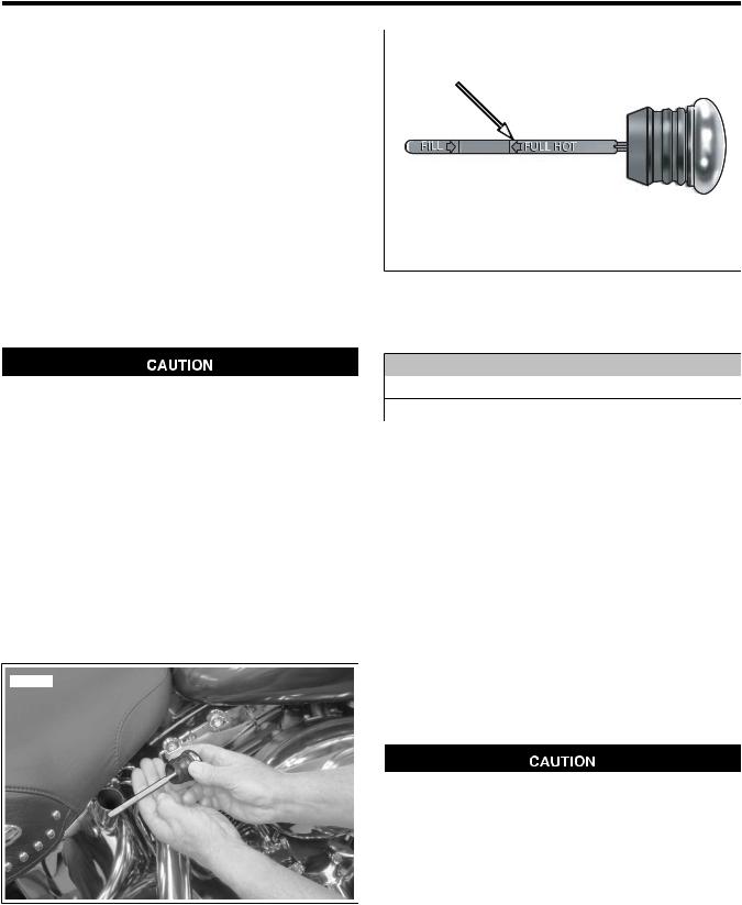
ENGINE OIL AND FILTER
CHECKING AND ADDING OIL
See Figure 1-1. Checking engine oil level:
•As part of the pre-ride inspection.
•At every scheduled service interval.
Type of Oil
Refer to Table 1-5. Use the proper grade of oil for the lowest temperature expected before the next oil change. See 1.3 FUEL AND OIL for specific information regarding winter needs.
If it is necessary to add oil and Harley-Davidson oil is not available, use an oil certified for diesel engines. Acceptable diesel engine oil designations include CF-4, CG-4, CH-4, and CI-4. The preferred viscosities for the diesel engine oils, in descending order, are 20W-50, 15W-40 and 10W-40. At the first opportunity, see a Harley-Davidson dealer to change back to 100 percent Harley-Davidson oil.
Checking Oil Level
Oil level cannot be accurately measured on a cold engine. For pre-ride inspection, with motorcycle leaning on jiffy stand on level ground, oil should register on dipstick between arrows when engine is cold. Do not add oil to bring the level to the FULL mark on a COLD engine. (00185a)
Ride motorcycle until engine is warmed up to operating temperature, then do the following.
1.Idle motorcycle on jiffy stand for 1-2 minutes.
2.Shut motorcycle off and leave motorcycle resting on jiffy stand.
3.See Figure 1-2. Check oil level on dipstick. If necessary, add oil until oil registers at upper groove on dipstick. Do not overfill oil tank.
sm03037
Figure 1-1. Checking Oil Tank Level
1.5
sm03039
Figure 1-2. Oil Tank Dipstick Upper Groove
CHANGING OIL AND FILTER
PART NUMBER |
TOOL NAME |
HD-42311 |
OIL FILTER WRENCH |
HD-44067 |
OIL FILTER WRENCH |
NOTES
•If the motorcycle is ridden hard, under dusty conditions, or in cold weather, the oil and filter should be changed more often.
•All Softail models are shipped from the factory with SAE 20W50 Harley-Davidson 360 Motor Oil.
•All Softail models come equipped from the factory with a premium 5 micron synthetic media oil filter, Part No. 63798-99 (Chrome) or 63731-99 (Black). These are the only recommended replacement filters.
1.Ride motorcycle until engine is warmed up to normal operating temperature.
2.See Figure 1-1. Remove the engine oil filler plug/dipstick by pulling steadily while moving plug back and forth.
3.See Figure 1-3. Remove the engine oil drain plug with o- ring (2). Allow oil to drain into a suitable container.
Use Harley-Davidson oil filter wrench for filter removal. This tool can prevent damage to crankshaft position sensor and/or sensor cable. (00192b)
4.See Figure 1-4. Remove the oil filter using the OIL FILTER WRENCH (Part No. HD-42311) or OIL FILTER WRENCH (Part No. HD-44067). Clean the oil filter mounting surface of any old gasket material.
5.See Figure 1-5. Lube the gasket on new oil filter with engine oil and install new filter. Hand tighten oil filter 1/2 to 3/4 turn after gasket contacts filter mounting surface. DO NOT use oil filter wrench for oil filter installation.
1-12 2008 Softail Service: Maintenance

6.See Figure 1-3. Install oil tank drain plug (2).
a.Inspect o-ring for tears or damage. Replace if required. Wipe any foreign material from plug.
b.Install o-ring and drain plug. Tighten to 14-21 ftlbs (19.0-28.5 Nm).
7.Fill oil tank with the correct amount of oil. Use the proper grade of oil for the lowest temperature expected before next oil change. Refer to Table 1-5.
a.Use 2.5 quarts (2.4 liters) of engine oil for a wet capacity refill.
b.Use 3.0 quarts (2.7 liters) for a dry capacity refill.
NOTE
Use wet capacity values for engines that have just had the oil drained. Use dry capacity values for engines that have been disassembled, cleaned in solvent and dried.
8.Check engine oil level using cold check procedure.
9.Start engine and carefully check for oil leaks around drain plug and oil filter.
10.Check engine oil level using hot check procedure.
sm01673
Figure 1-4. Oil Filter Wrenches
sm01414
sm03041
Figure 1-5. Lubricating New Oil Filter Gasket
1.Frame connection for oil tank drain hose
2.Oil tank drain plug and O-ring
Figure 1-3. Oil Tank Drain Plug
2008 Softail Service: Maintenance 1-13
Loading...