


 Loading...
Jade's Collection .net Archives
1
CHAPTER ONE
GENERAL INFORMATION
This detailed and comprehensive manual covers 1986-2003 XL/XLH Sportster models. The text provides complete information on maintenance, tune-up, repair and overhaul. Hundreds of photos and drawings guide the reader through every job.
A shop manual is a reference tool and as in all Service manuals, the chapters are thumb tabbed for easy reference. Important items are indexed at the end of the book. All procedures, tables and figures are designed for the reader who may be working on the motorcycle for the first time. Frequently used specifications and capacities from individual chapters are summarized in the Quick Reference Data at the front of this manual.
MANUAL ORGANIZATION
All dimensions and capacities are expressed in U.S. standard and metric units of measurement.
Specifications, when applicable, are listed in the tables at the end of each chapter.
This chapter covers shop safety, tool use, service fundamentals and shop supplies. Tables 1-12 at the end of the chapter include the following:
1. Model designations.
2.General motorcycle dimensions.
3.Motorcycle weight.
4.Gross vehicle weight.
5.Fuel tank capacity.
6.General torque recommendations.
7.Conversion formulas.
8.Technical abbreviations.
9.U.S. standard tap and drill sizes.
10.Metric tap and drill sizes.
11.Decimal and metric equivalents.
12.Special tools.
Chapter Two provides methods for quick and accurate diagnosis of problems. Troubleshooting procedures present typical symptoms and logical methods to pinpoint and repair the problem.
Chapter Three explains all routine maintenance necessary to keep the motorcycle running well. Chapter Three also includes recommended tune-up procedures, eliminating the need to constantly consult the chapters on the various assemblies.
Subsequent chapters describe specific systems such as engine, primary drive and clutch, transmission, emissions, fuel and exhaust systems, the electrical system, suspension, brakes and body. Each disassembly, repair and assembly procedure is discussed in step-by-step form.

2 |
CHAPTER ONE |
WARNINGS, CAUTIONS AND NOTES
The terms, WARNING, CAUTION and NOTE have specific meanings in this manual.
A WARNING emphasizes areas where injury or even death could result from negligence. Mechanical damage may also occur. WARNINGS are to be taken seriously.
A CAUTION emphasizes areas where equipment damage could result. Disregarding a CAUTION could cause permanent mechanical damage, though injury is unlikely.
A NOTE provides additional information to make a step or procedure easier or clearer. Disregarding a NOTE could cause inconvenience, but would not cause equipment damage or personal injury.
SAFETY
Professional mechanics can work for years and never sustain a serious injury or mishap. Follow these guidelines and practice common sense to safely service the motorcycle.
1.Do not operate the motorcycle in an enclosed area. The exhaust gasses contain carbon monoxide, an odorless, colorless and tasteless poisonous gas. Carbon monoxide levels build quickly in small enclosed areas and can cause unconsciousness and death in a short time. Make sure the work area is properly ventilated or operate the motorcycle outside.
2.Never use gasoline or any flammable liquid to clean parts. Refer to Handling Gasoline Safely and Cleaning Parts in this section.
3.Never smoke or use a torch in the vicinity of flammable liquids.
4.If welding or brazing on the motorcycle, remove the fuel tank, carburetor and shocks to a safe distance at least 50 ft. (15 m) away.
5.Use the correct type and size tools to avoid damaging fasteners.
6.Keep tools clean and in good condition. Replace or repair worn or damaged equipment.
7.When loosening a tight fastener, be guided by what would happen if the tool slips.
8.When replacing fasteners, make sure the new fasteners are of the same size and strength as the original ones.
9.Keep the work area clean and organized.
10.Wear eye protection any time eye safety is in question. This includes procedures involving drilling, grinding, hammering, compressed air and chemicals.
11.Wear the correct clothing for the job. Tie up or cover long hair so it can not get caught in moving equipment.
12.Do not carry sharp tools in clothing pockets.
13.Always have an approved fire extinguisher available. Make sure it is rated for gasoline (Class B) and electrical (Class C) fires.
14.Do not use compressed air to clean clothes, the motorcycle or the work area. Debris may be blown into your eyes or skin. Never direct compressed air at anyone. Do not al-
1
low children to use or play with any compressed air equipment.
15.When using compressed air to dry rotating parts, hold the part so it can not rotate. Do not allow the force of the air to spin the part. The air jet is capable of rotating parts at extreme speed. The part may be damaged or disintegrate, causing serious injury.
16.Do not inhale the dust created by brake pad and clutch wear. These particles may contain asbestos. In addition, some types of insulating materials and gaskets may contain asbestos. Inhaling asbestos particles is hazardous to health.
17.Never work on the motorcycle while someone is working under it.
18.When placing the motorcycle on a stand, make sure it is secure before walking away.
Handling Gasoline Safely
Gasoline is a volatile flammable liquid and is one of the most dangerous items in the shop. Because gasoline is used so often, many people forget that it is hazardous. Only use gasoline as fuel for gasoline internal combustion engines. Keep in mind, when working on a motorcycle, gasoline is always present in the fuel tank, fuel line and carburetor. To avoid an accident when working around the fuel system, carefully observe the following precautions:
1.Never use gasoline to clean parts. See Cleaning Parts in this section.
2.Wear protective gloves to prevent skin contact with gasoline. If your skin contacts gasoline, wash thoroughly with soap and water.
3.When working on the fuel system, work outside or in a well-ventilated area.
4.Do not add fuel to the fuel tank or service the fuel system while the motorcycle is near open flames, sparks or where someone is smoking. Gasoline vapor is heavier than air, it collects in low areas and is more easily ignited than liquid gasoline.
5.Allow the engine to cool completely before working on any fuel system component.

GENERAL INFORMATION |
3 |
2
3
6.When draining the carburetor, catch the fuel in a plastic container and then pour it into an approved gasoline storage devise.
7.Do not store gasoline in glass containers. If the glass breaks, an explosion or fire may occur.
8.Immediately wipe up spilled gasoline with rags. Store the rags in a metal container with a lid until they can be properly disposed of, or place them outside in a safe place for the fuel to evaporate.
9.Do not pour water onto a gasoline fire. Water spreads the fire and makes it more difficult to put out. Use a class B, BC or ABC fire extinguisher to extinguish the fire.
10.Always turn off the engine before refueling. Do not spill fuel onto the engine or exhaust system. Do not overfill the fuel tank. Leave an air space at the top of the tank to allow room for the fuel to expand due to temperature fluctuations.
Cleaning Parts
Cleaning parts is one of the more tedious and difficult service jobs performed in the home garage. There are many types of chemical cleaners and solvents available for shop use. Most are poisonous and extremely flammable. To prevent chemical exposure, vapor buildup, fire and serious injury, observe each product warning label and note the following:
1. Read and observe the entire product label before using |
1 |
any chemical. Always know what type of chemical is being used and whether it is poisonous and/or flammable.
2.Do not use more than one type of cleaning solvent at a time. If mixing chemicals is called for, measure the proper amounts according to the manufacturer.
3.Work in a well-ventilated area.
4.Wear protective gloves.
5.Wear safety glasses.
6.Wear a vapor respirator if the instructions call for it.
7.Wash hands and arms thoroughly after cleaning parts.
8.Keep chemical products away from children and pets.
9.Thoroughly clean all oil, grease and cleaner residue from any part that must be heated.
10.Use a nylon brush to clean parts. Metal brushes may cause a spark.
11.When using a parts washer, only use the solvent recommended by the manufacturer. Make sure the parts washer is equipped with a metal lid that will lower in case of fire.
Warning Labels
Most manufacturers attach information and warning labels to the motorcycle. These labels contain instructions that are important to personal safety when operating, servicing, transporting and storing the motorcycle. Refer to the owner’s manual for the description and location of labels. Order replacement labels from the manufacturer if they are missing or damaged.
SERIAL NUMBERS
Serial numbers are stamped on various locations on the frame, engine and carburetor. Record these numbers in the Quick Reference Data section in the front of the book. Have these numbers available when ordering parts.
The VIN number is stamped on the right side of the steering head (Figure 1). The VIN number also appears on a label affixed to the right, front frame downtube.
The engine serial number is stamped on a pad at the left side surface of the crankcase between the cylinders (Figure 2). The engine serial number consists of digits used in the VIN number.
The carburetor serial number (Figure 3) is located adjacent to the accelerator pump linkage.
NOTE
In addition to model year designations, Harley-Davidson also uses early and late model designations. Refer to the “Introduction Date and Special Models” information in Figure 4 to help determine the model identity of a motorcycle. If in doubt, take the VIN number to a dealership.

Jade's Collection .net Archives |
|
|
4 |
CHAPTER ONE |
|
4 |
VEHICLE IDENTIFICATION NUMBER (VIN) |
|
(1986-2003 SPORTSTER) |
||
|
Motorcycle |
|
Model Designation |
Made in U.S.A. |
|
CA = XLH883, XLH883 Deluxe |
|
|
(1986/1987), XLH1100, |
|
||
|
|
XLH1200 |
|
|
CE = XLH883 Hugger |
|
|
CF = XLH833 Deluxe |
|
|
CG = XL1200 Custom |
|
|
CH = XL1200 Sport |
|
|
CJ = XLH883 Custom |
|
|
CK = XLH883 Custom |
|
|
|
Engine Size
M = 883 cc engine
N = 1100 cc engine
P = 1200 cc engine
Introduction Date and Special Models
1= Regular introduction date
2= Mid-year introduction date
3= California model
4= Special edition
5= California-only special edition
VIN Check Digit
Varies; can be 0 through 9, or X.
1 |
HD |
4 |
CA |
M |
1 |
3 |
R |
Y |
Y |
Model Year
M = 1991 N = 1992 P = 1993 R = 1994 S = 1995 T = 1996 V = 1997 W = 1998 X = 1999 Y = 2000
1= 2001
2= 2002
3= 2003
Manufacturer and Make
Harley Davidson
Assembly Plant
K = Kansas City
Y = York, Pennsyvania
Motorcycle Type
1 = Heavyweight (901 cc and larger engine displacement)
4 = Middleweight (351-900 cc engine displacement)
FASTENERS
Proper fastener selection and installation is important to ensure the motorcycle operates as designed and can be serviced efficiently. The choice of original equipment fasteners is not arrived at by chance. Make sure that replacement fasteners meet all the same requirements as the originals.
Threaded Fasteners
WARNING
Do not install fasteners with a strength classification lower than what was originally installed by the manufacturer. Doing so may cause equipment failure and/or damage.
Threaded fasteners secure most of the components on the motorcycle. Most are tightened by turning them clockwise (right-hand threads). If the normal rotation of the component being tightened would loosen the fastener, it may have left-hand threads. If a left-hand threaded fastener is used, it is noted in the text.
Two dimensions are required to match the size of the fastener: the number of threads in a given distance and the outside diameter of the threads.
Two systems are currently used to specify threaded fastener dimensions: the U.S. Standard system and the metric system (Figure 5). Pay particular attention when working with unidentified fasteners; mismatching thread types can damage threads.

GENERAL INFORMATION |
5 |
5
U.S. Standard |
Metric |
60° |
60° |
|
6
T
D
L
Grade marking
NOTE
To ensure that the fastener threads are not mismatched or cross-threaded, start all fasteners by hand. If a fastener is hard to start or turn, determine the cause before tightening with a wrench.
The length (L, Figure 6), diameter (D) and number of threads per inch (TPI) (T) classify U.S. Standard screws and bolts. A typical bolt may be identified by the numbers 1/4Ð20×1-1/2. This indicates the bolt has a 1/4-inch diameter, 20 threads per inch and the length is 1-1/2 inches. Sometimes thread count is noted as either course or fine. Always measure bolt length as shown in L, Figure 6 to avoid purchasing replacements of the wrong length.
Markings on top of the fastener (Figure 6) indicate the strength of U.S. Standard screws and bolts. The greater the number of head markings, the stronger the fastener. Unmarked fasteners are the weakest.
Many screws, bolts and studs are combined with nuts to secure particular components. To indicate the size of a nut, manufacturers specify the internal diameter and the TPI.
The measurement across two flats on a nut or bolt indi- |
1 |
cates the wrench size.
Torque Specifications
The materials used in the manufacture of the motorcycle may be subjected to uneven stresses if the fasteners of the various subassemblies are not installed and tightened correctly. Fasteners that are improperly installed or work loose can cause extensive damage. It is essential to use an accurate torque wrench, as described in this chapter, with the torque specifications in this manual.
Specifications for torque are provided in foot-pounds (ft.-lb.), inch-pounds (in.-lb.) and Newton-meters (N¥m). Refer to Table 6 for general torque specifications. To use Table 6, first determine the size of the fastener as described in this section. Torque specifications for specific components are at the end of the appropriate chapters. Torque wrenches are covered in this chapter.
Self-Locking Fasteners
Several types of bolts, screws and nuts incorporate a system that creates interference between the two fasteners. Interference is achieved in various ways. The most common types are the nylon insert nut and a dry adhesive coating on the threads of a bolt.
Self-locking fasteners offer greater holding strength than standard fasteners, which improves their resistance to vibration. Self-locking fasteners cannot be reused. The material used to form the lock becomes distorted after the initial installation and removal. Discard and replace self-locking fasteners after their removal. Do not replace self-locking fasteners with standard fasteners.
Washers
There are two basic types of washers: flat washers and lockwashers. Flat washers are simple discs with a hole to fit a screw or bolt. Lockwashers are used to prevent a fastener from working loose. Washers can be used as spacers and seals, or to help distribute fastener load and to prevent the fastener from damaging the component.
As with fasteners, when replacing washers make sure the replacement washers are of the same design and quality.
Cotter Pins
A cotter pin is a split metal pin inserted into a hole or slot to prevent a fastener from loosening. In certain applications, such as the rear axle on a motorcycle, the fastener must be secured in this way. For these applications, a cotter pin and castellated (slotted) nut are used.
To use a cotter pin, first make sure the diameter is correct for the hole in the fastener. After correctly tightening the

6 |
CHAPTER ONE |
fastener and aligning the holes, insert the cotter pin through the hole and bend the ends over the fastener (Figure 7). Unless instructed to do so, never loosen a tightened fastener to align the holes. If the holes do not align, tighten the fastener just enough to achieve alignment.
Cotter pins are available in various diameters and lengths. Measure length from the bottom of the head to the tip of the shortest pin.
Snap Rings and E-clips
Snap rings (Figure 8) are circular-shaped metal retaining clips. They are required to secure parts and gears in place on parts such as shafts, pins or rods. External type snap rings are used to retain items on shafts. Internal type snap rings secure parts within housing bores. In some applications, in addition to securing the component(s), snap rings of varying thickness also determine endplay. These are usually called selective snap rings.
Two basic types of snap rings are used: machined and stamped snap rings. Machined snap rings can be installed in either direction, since both faces have sharp edges. Stamped snap rings (Figure 9) are manufactured with a sharp edge and a round edge. When installing a stamped circlip in a thrust application, install the sharp edge facing away from the part producing the thrust (Figure 10).
E-clips are used when it is not practical to use a circlip. Remove E-clips with a flat blade screwdriver by prying between the shaft and E-clip. To install an E-clip, center it over the shaft groove and push or tap it into place.
Observe the following when installing snap rings:
1.Remove and install snap rings with circlip pliers. Refer to the Tools section in this chapter.
2.In some applications, it may be necessary to replace snap rings after removing them.
3.Compress or expand snap rings only enough to install them. If overly expanded, they lose their retaining ability.
4.After installing a snap ring, make sure it seats completely.
5.Wear eye protection when removing and installing snap rings.
SHOP SUPPLIES
Lubricants and Fluids
Periodic lubrication helps ensure a long service life for any type of equipment. Using the correct type of lubricant is as important as performing the lubrication service, although in an emergency the wrong type is better than not using one. The following section describes the types of lubricants most often required. Make sure to follow the manufacturer’s recommendations for lubricant types.
7
Correct installation of cotter pin
8
Internal snap ring |
Plain circlip |
External snap ring |
E-clip |
Engine oils
Engine oil is classified by two standards: the American Petroleum Institute (API) service classification and the Society of Automotive Engineers (SAE) viscosity rating. This information is on the oil container label. Two letters indicate the API service classification. The number or sequence of numbers and letter (10W-40 for example) is the oil’s viscosity rating. The API service classification and the SAE viscosity index are not indications of oil quality.
The service classification indicates that the oil meets specific lubrication standards. The first letter in the classification, S, indicates the oil is for gasoline engines.

GENERAL INFORMATION |
7 |
9
Rounded edges
Sharp edges
Direction of thrust
10
Full support Direction of areas thrust
When selecting an API classified oil, make sure the classification is correct (Chapter Three, Table 3) and the circular API service label does not indicate the oil is for ENERGY CONSERVING. This type of oil is not designed for motorcycle applications. Using oil with the incorrect classification can cause engine damage.
In addition to the API classification, some oils carry the Japanese Automobile Standards Organization (JASO) classification for use in motorcycle engines. These motorcycle specific oils (JASO T 903 Standard) with the MA (high-friction applications) designation are designed for motorcycle applications.
Always use an oil with a classification recommended by the manufacturer. Using an oil with a different classification can cause engine damage.
Viscosity is an indication of the oil’s thickness. Thin oils have a lower number while thick oils have a higher number. Engine oils fall into the 5- to 50-weight range for sin- gle-grade oils.
Most manufacturers recommend multi-grade oil. These oils perform efficiently across a wide range of operating conditions. Multi-grade oils are identified by a W after the first number, which indicates the low-temperature viscosity.
Engine oils are most commonly mineral (petroleum) |
1 |
based; however, synthetic and semi-synthetic types are being used more frequently. When selecting engine oil, follow the manufacturer’s recommendation for type, classification and viscosity when selecting engine oil. Refer to Chapter Three, Table 3.
Greases
Grease is lubricating oil with thickening agents added to it. The National Lubricating Grease Institute (NLGI) grades grease. Grades range from No. 000 to No. 6, with No. 6 being the thickest. Typical multipurpose grease is NLGI No. 2. For specific applications, manufacturers may recommend water-resistant grease or one with an additive such as molybdenum disulfide (MoS2).
Brake fluid
WARNING
Never put a mineral-based (petroleum) oil into the brake system. Mineral oil will cause rubber parts in the system to swell and break apart, resulting in complete brake failure.
Brake fluid is the hydraulic fluid used to transmit hydraulic pressure (force) to the wheel brakes. Brake fluid is classified by the Department of Transportation (DOT). This classification, DOT 5 for example, appears on the fluid container.
Each type of brake fluid has its own definite characteristics. Do not intermix different types of brake fluid as this may cause brake system failure. DOT 5 brake fluid is silicone based. DOT 5 is not compatible with other brake fluids or in systems for which it was not designed. Mixing DOT 5 fluid with other fluids may cause brake system failure. When adding brake fluid, only use the fluid recommended by the manufacturer. Refer to Chapter Three,
Table 5.
Brake fluid will damage any plastic, painted or plated surface it contacts. Use care when working with brake fluid and clean any spills immediately with soap and water.
Hydraulic brake systems require clean and moisture free brake fluid. Never reuse brake fluid. Keep containers and reservoirs properly sealed.
Coolant
Coolant is a mixture of water and antifreeze used to dissipate engine heat. Ethylene glycol is the most common form of antifreeze used. Check the motorcycle manufacturer’s recommendations (Chapter Three, Table 5) when selecting antifreeze; most require one specifically designed for use in aluminum engines. These types of antifreeze have additives that inhibit corrosion.

8 |
CHAPTER ONE |
Only mix distilled water with antifreeze. Impurities in tap water may damage internal cooling system passages.
Cleaners, Degreasers and Solvents
Many chemicals are available to remove oil, grease and other residue from the motorcycle. Before using cleaning solvents, consider how they will be used and disposed of, particularly if they are not water-soluble. Local ordinances may require special procedures for the disposal of many types of cleaning chemicals. Refer to Safety in this chapter for more information on their use.
Use brake parts cleaner to clean brake system components, contact with petroleum-based products will damage seals. Brake parts cleaner leaves no residue. Use electrical contact cleaner to clean electrical connections and components without leaving any residue. Carburetor cleaner is a powerful solvent used to remove fuel deposits and varnish from fuel system components. Use this cleaner carefully, as it may damage finishes.
Generally, degreasers are strong cleaners used to remove heavy accumulations of grease from engine and frame components.
Most solvents are designed to be used with a parts washing cabinet for individual component cleaning. For safety, use only nonflammable or high flash point solvents.
Gasket Sealant
Sealants are often used in combination with a gasket or seal and are occasionally alone. Follow the manufacturer’s recommendation when using sealants. Use care when choosing a sealant different from the type originally recommended. Choose sealants based on their resistance to heat, various fluids and their sealing capabilities.
One of the most common sealants is RTV, or room temperature vulcanizing sealant. This sealant cures at room temperature over a specific time period. This allows the repositioning of components without damaging gaskets.
Moisture in the air causes the RTV sealant to cure. Always install the tube cap as soon as possible after applying RTV sealant. RTV sealant has a limited shelf life and will not cure properly if the shelf life has expired. Keep partial tubes sealed and discard them if they have surpassed the expiration date.
Applying RTV sealant
Clean all old gasket residue from the mating surfaces. Remove all gasket material from blind threaded holes; it can cause inaccurate bolt torque. Spray the mating surfaces with aerosol parts cleaner and then wipe with a lint-free cloth. The area must be clean for the sealant to adhere.
Apply RTV sealant in a continuous bead 0.08-0.12 in. (2-3 mm) thick. Circle all the fastener holes unless otherwise specified. Do not allow any sealant to enter these
11
holes. Assemble and tighten the fasteners to the specified torque within the time frame recommended by the RTV sealant manufacturer.
Gasket Remover
Aerosol gasket remover can help remove stubborn gaskets. This product can speed up the removal process and prevent damage to the mating surface that may be caused by using a scraping tool. Most of these types of products are very caustic. Follow the gasket remover manufacturer’s instructions for use.
Threadlocking Compound
CAUTION
Threadlocking compounds are anaerobic and will damage most plastic parts and surfaces. Use caution when using these products in area where plastic components are located.
A threadlocking compound is a fluid applied to the threads of fasteners. After tightening the fastener, the fluid dries and becomes a solid filler between the threads. This makes it difficult for the fastener to work loose from vibration, or heat expansion and contraction. Some threadlocking compounds also provide a seal against fluid leaks.
Before applying threadlocking compound, remove any old compound from both thread areas and clean them with aerosol parts cleaner. Use the compound sparingly. Excess fluid can run into adjoining parts.
Threadlocking compounds are available in different strength, temperature and repair application. Follow the manufacturer’s recommendations regarding compound selection.
TOOLS
Most of the procedures in this manual can be carried out with simple hand tools and test equipment familiar to the

GENERAL INFORMATION |
9 |
12
home mechanic. Always use the correct tools for the job at hand. Keep tools organized and clean. Store them in a tool chest with related tools organized together.
Quality tools are essential. The best are constructed of high-strength alloy steel. These tools are light, easy to use and resistant to wear. Their working surface is devoid of sharp edges and the tool is carefully polished. They have an easy-to-clean finish and are comfortable to use. Quality tools are a good investment.
When purchasing tools to perform the procedures covered in this manual, consider the tool’s potential frequency of use. If starting a new tool kit, consider purchasing a basic tool set from a quality tool supplier. These sets are available in many tool combinations and offer substantial savings when compared to individually purchased tools. As work experience grows and tasks become more complicated, specialized tools can be added.
Some of the procedures in this manual specify special tools. Refer to Table 12. In most cases, the tool is illustrated in use. Well-equipped mechanics may be able to substitute similar tools or fabricate a suitable replacement. However, in some cases, the specialized equipment or expertise may make it impractical for the home mechanic to attempt the procedure. When necessary, such operations are identified in the text with the recommendation to have a dealership or specialist perform the task. It may be less expensive to have a professional perform these jobs, especially when considering the cost of the equipment.
The manufacturer’s part number is provided for many of the tools mentioned in this manual. These part numbers are correct at the time of original publication. The publisher cannot guarantee the part number or the tools in this manual will be available in the future.
As with all tools, use a screwdriver designed for the job. |
1 |
Make sure the size of the tip conforms to the size and shape of the fastener. Use them only for driving screws. Never use a screwdriver for prying or chiseling metal. Repair or replace worn or damaged screwdrivers. A worn tip may damage the fastener, making it difficult to remove.
Wrenches
Open-end, box-end and combination wrenches (Figure 11) are available in a variety of types and sizes.
The number stamped on the wrench refers to the distance between the work areas. This size must match the size of the fastener head.
The box-end wrench is an excellent tool because it grips the fastener on all sides. This reduces the chance of the tool slipping. The box-end wrench is designed with either a 6- or 12-point opening. For stubborn or damaged fasteners, the 6-point provides superior holding ability by contacting the fastener across a wider area at all six edges. For general use, the 12-point works well. It allows the wrench to be removed and reinstalled without moving the handle over such a wide arc.
An open-end wrench is fast and works best in areas with limited overhead access. It contacts the fastener at only two points, and is subject to slipping under heavy force, or if the tool or fastener is worn. A box-end wrench is preferred in most instances, especially when breaking loose and applying the final tightness to a fastener.
The combination wrench has a box-end on one end, and an open-end on the other. This combination makes it a very convenient tool.
Adjustable Wrenches
An adjustable wrench, or Crescent wrench (Figure 12), can fit nearly any nut or bolt head that has clear access around its entire perimeter. Adjustable wrenches are best used as a backup wrench to keep a large nut or bolt from turning while the other end is being loosened or tightened with a box-end or socket wrench.
Adjustable wrenches contact the fastener at only two points, which makes them more subject to slipping off the fastener. The fact that one jaw is adjustable and may loosen only aggravates this shortcoming. Make certain the solid jaw is the one transmitting the force.
Screwdrivers
Screwdrivers of various lengths and types are mandatory for the simplest tool kit. The two basic types are the slotted tip (flat blade) and the Phillips tip. These are available in sets that often include an assortment of tip sizes and shaft lengths.
Socket Wrenches, Ratchets and Handles
WARNING
Do not use hand sockets with air or impact tools, as they may shatter and cause injury. Always wear eye protection when using impact or air tools.
10 |
CHAPTER ONE |
Sockets that attach to a ratchet handle are available with 6-point (A, Figure 13) or 12-point (B) openings and different drive sizes (Figure 14) . The drive size indicates the size of the square hole that accepts the ratchet handle. The number stamped on the socket is the size of the work area and must match the fastener head.
As with wrenches, a 6-point socket provides supe- rior-holding ability, while a 12-point socket needs to be moved only half as far to reposition it on the fastener.
Sockets are designated for either hand or impact use. Impact sockets are made of thicker material for more durability. Compare the size and wall thickness of a 19-mm hand socket (A, Figure 15) and the 19-mm impact socket (B). Use impact sockets when using an impact driver or air tools. Use hand sockets with hand-driven attachments.
Various handles are available for sockets. The speed handle is used for fast operation. Flexible ratchet heads in varying lengths allow the socket to be turned with varying force, and at odd angles. Extension bars allow the socket setup to reach difficult areas. The ratchet is the most versatile. It allows the user to install or remove the nut without removing the socket.
Sockets combined with any number of drivers make them undoubtedly the fastest, safest and most convenient tool for fastener removal and installation.
Impact Driver
WARNING
Do not use hand sockets with air or impact tools as they may shatter and cause injury. Always wear eye protection when using impact or air tools.
An impact driver provides extra force for removing fasteners, by converting the impact of a hammer into a turning motion. This makes it possible to remove stubborn fasteners without damaging them. Impact drivers and interchangeable bits (Figure 16) are available from most tool suppliers. When using a socket with an impact driver make sure the socket is designed for impact use. Refer to Socket Wrenches, Ratchets and Handles in this section.
Allen Wrenches
Allen wrenches (Figure 17) are used on fasteners with hexagonal recesses in the fastener head. These wrenches are available in L-shaped bar, socket and T-handle types. Allen bolts are sometimes called socket bolts or setscrews.
Torque Wrenches
A torque wrench (Figure 18) is used with a socket, torque adapter or similar extension to tighten a fastener to a measured torque. Torque wrenches come in several drive sizes (1/4, 3/8, 1/2 and 3/4) and have various meth-
13
14
15
16
GENERAL INFORMATION |
11 |
17 |
20 |
1 |
|
||
|
L |
A |
|
L |
A |
|
L + A = Effective lever length |
|
|
L |
|
18 |
L = Effective lever length |
L |
No calculation needed
19
ods for reading the torque value. The drive size indicates the size of the square drive that accepts the socket, adapter or extension. Common methods for reading the torque value are the reflecting beam, the dial indicator and the audible click.
When choosing a torque wrench, consider the torque range, drive size and accuracy. The torque specifications in this manual provide an indication of the range required.
A torque wrench is a precision tool that must be properly cared for to remain accurate. Store torque wrenches in cases or separate padded drawers within a toolbox. Follow the manufacturerÕs instructions for their care and calibration.
Torque Adapters
Torque adapters or extensions extend or reduce the reach of a torque wrench. The torque adapter shown in Figure 19 is used to tighten a fastener that cannot be reached due to the size of the torque wrench head, drive, and socket. If a torque adapter changes the effective lever length (Figure 20), the torque reading on the wrench will not equal the actual torque applied to the fastener. It is necessary to recalibrate the torque setting on the wrench to compensate for the change of lever length. When a torque adapter is used at a right angle to the drive head, calibration is not required, since the effective length has not changed.
To recalculate a torque reading when using a torque adapter, use the following formula, and refer to Figure 20.
TW = TA ×L L + A
TW is the torque setting or dial reading on the wrench. TA is the torque specification and the actual amount of
torque that will be applied to the fastener.
A is the amount that the adapter increases (or in some cases reduces) the effective lever length as measured along the centerline of the torque wrench.
L is the lever length of the wrench as measured from the center of the drive to the center of the grip.
The effective length is the sum of L and A. Example:
TA = 20 ft.-lb. A = 3 in.
L = 14 in.
TW = 20 ×14 = 280 = 16.5 ft.-lb. 14 + 3 17

12 |
CHAPTER ONE |
In this example, the torque wrench would be set to the recalculated torque value (TW = 16.5 ft.-lb.) . When using a beam-type wrench, tighten the fastener until the pointer aligns with 16.5 ft.-lb. In this example, although the torque wrench is preset to 16.5 ft.-lb., the actual torque is 20 ft.-lb.
Pliers
Pliers come in a wide range of types and sizes. Pliers are useful for holding, cutting, bending, and crimping. Do not use them to turn fasteners. Figure 21 and Figure 22 show several types of pliers. Each design has a specialized function. Slip-joint pliers are general-purpose pliers used for gripping and bending. Diagonal cutting pliers are needed to cut wire and can be used to remove cotter pins. Needlenose pliers are used to hold or bend small objects. Locking pliers (Figure 22), sometimes called Vise-grips, are used to hold objects very tightly. They have many uses ranging from holding two parts together, to gripping the end of a broken stud. Use caution when using locking pliers, as the sharp jaws will damage the objects they hold.
Snap Ring Pliers
WARNING
Snap rings can slip and fly off when removing and installing them. Also, the snap ring pliers tips may break. Always wear eye protection when using snap ring pliers.
Snap ring pliers are specialized pliers with tips that fit into the ends of snap rings to remove and install them.
Snap ring pliers are available with a fixed action (either internal or external) or convertible (one tool works on both internal and external snap rings). They may have fixed tips or interchangeable ones of various sizes and angles. For general use, select a convertible type of pliers with interchangeable tips.
Hammers
Various types of hammers (Figure 23) are available to fit a number of applications. A ball-peen hammer is used to strike another tool, such as a punch or chisel. Soft-faced hammers are required when a metal object must be struck without damaging it. Never use a metal-faced hammer on engine and suspension components, as damage will occur.
Always wear eye protection when using hammers. Make sure the hammer face is in good condition and the handle is not cracked. Select the correct hammer for the job and make sure to strike the object squarely. Do not use the handle or the side of the hammer to strike an object.
21
22
23
MEASURING TOOLS
The ability to accurately measure components is essential to successfully complete many procedures in this manual. Equipment is manufactured to close tolerances, and obtaining consistently accurate measurements is essential to determining which components require replacement or further service.
Each type of measuring instrument is designed to measure a dimension with a certain degree of accuracy and within a certain range. When selecting the measuring tool, make sure it is applicable to the task. Refer to Figure 24 for a comprehensive measuring set.
As with all tools, measuring tools provide the best results if cared for properly. Improper use can damage the tool and

GENERAL INFORMATION |
13 |
1
24 27
10.00 mm
0.50 mm
10.50 mm Fixed scale
25
26
result in inaccurate results. If any measurement is questionable, verify the measurement using another tool. A standard gauge is usually provided with measuring tools to check accuracy and calibrate the tool if necessary.
Precision measurements can vary according to the experience of the person performing the procedure. Accurate results are only possible if the mechanic possesses a feel for using the tool. Heavy-handed use of measuring tools will produce less accurate results. Hold the tool gently by the fingertips so the point at which the tool contacts the object is easily felt. This feel for the equipment will produce more accurate measurements and reduce the risk of damaging the tool or component. Refer to the following sections for specific measuring tools.
0.400 in.
0.013 in. Moveable scales
0.413 in.
Feeler Gauge
The feeler or thickness gauge (Figure 25) is used for measuring the distance between two surfaces.
A feeler gauge set consists of an assortment of steel strips of graduated thickness. Each blade is marked with its thickness. Blades can be of various lengths and angles for different procedures.
A common use for a feeler gauge is to measure valve clearance. Wire (round) type gauges are used to measure spark plug gap.
Calipers
Calipers (Figure 26) are excellent tools for obtaining inside, outside and depth measurements. Although not as precise as a micrometer, they allow reasonable precision, typically to within 0.001 in. (0.05 mm). Most calipers have a range up to 6 in. (150 mm).
Calipers are available in dial, vernier or digital versions. Dial calipers have a dial readout that provides convenient reading. Vernier calipers have marked scales that must be compared to determine the measurement. The digital caliper uses a LCD to show the measurement.
Properly maintain the measuring surfaces of the caliper. There must not be any dirt or burrs between the tool and the object being measured. Never force the caliper closed around an object; close the caliper around the highest point so it can be removed with a slight drag. Some calipers require calibration. Always refer to the manufacturer’s instructions when using a new or unfamiliar caliper.
To read a vernier caliper refer to Figure 27. The fixed scale is marked in 0.001 in. increments. Forty individual
14 |
CHAPTER ONE |
28 |
DECIMAL PLACE VALUES* |
|
|
0.1 |
Indicates 1/10 (one tenth of an inch |
|
or millimeter) |
0.010 |
Indicates 1/100 (one one-hundreth of |
|
an inch or millimeter) |
0.001 |
Indicates 1/1000 (one one-thousandth |
|
of an inch or millimeter) |
*This chart represents the values of figures placed to the right of the decimal point. Use it when reading decimals from one-tenth to one one-thousandth of an inch or millimeter. It is not a conversion chart (for example: 0.001 in. is not equal to 0.001 mm).
lines on the fixed scale equal 1 in. The moveable scale is
marked in 0.01 mm (hundredth) increments. To obtain a 29 reading, establish the first number by the location of the 0
line on the movable scale in relation to the first line to the left on the fixed scale. In this example, the number is 0.400 in. To determine the next number, note which of the lines on the movable scale align with a mark on the fixed scale. A number of lines will seem close, but only one will align exactly. In this case, 0.013 in. is the reading to add to the first number. The result of adding 0.400 in. and 0.013 in. is a measurement of 0.413 in.
Micrometers |
|
|
|
|
|
A micrometer is an instrument designed for linear mea- |
|
|
|
|
|
|
|
|
STANDARD |
|
|
surement using the decimal divisions of the inch or meter |
30 |
|
|
|
|
(Figure 28). While there are many types and styles of mi- |
|
INCH MICROMETER |
|
||
|
|
|
|||
crometers, most of the procedures in this manual call for an |
|
|
|
|
|
outside micrometer. The outside micrometer is used to mea- |
|
|
|
Locknut Sleeve line |
|
sure the outside diameter of cylindrical forms and the |
|
|
Spindle |
|
|
thickness of materials. |
|
Anvil |
Thimble marks |
|
|
|
|
|
|
||
A micrometer’s size indicates the minimum and maxi- |
|
|
|
|
|
mum size of a part that it can measure. The usual sizes (Fig- |
|
|
|
|
|
ure 29) are 0-1 in. (0-25 mm), 1-2 in. (25-50 mm), 2-3 in. |
|
|
|
Thimble |
Ratchet |
|
|
|
|
||
(50-75 mm) and 3-4 in. (75-100 mm). |
|
|
|
Sleeve numbers |
|
|
|
|
|
||
Micrometers that cover a wider range of measurements |
|
|
|
|
|
are available. These use a large frame with interchangeable |
|
|
|
Frame |
|
anvils of various lengths. This type of micrometer offers a |
|
|
|
|
|
|
|
|
|
|
|
cost savings; however, its overall size may make it less |
|
|
|
|
|
convenient. |
|
|
|
|
|
|
|
|
|
|
|
Adjustment
Before using a micrometer, check its adjustment as follows.
1. Clean the anvil and spindle faces.
2A. To check a 0-1 in. (0-25 mm) micrometer:
a.Turn the thimble until the spindle contacts the anvil. If the micrometer has a ratchet stop, use it to ensure that the proper amount of pressure is applied.
b.If the adjustment is correct, the 0 mark on the thimble will align exactly with the 0 mark on the sleeve line.
If the marks do not align, the micrometer is out of adjustment.
c.Follow the manufacturer’s instructions to adjust the micrometer.
2B. To check a micrometer larger than 1 in. (25 mm) use the standard gauge supplied by the manufacturer. A standard gauge is a steel block, disc or rod that is machined to an exact size.
a.Place the standard gauge between the spindle and anvil, and measure its outside diameter or length. If the

GENERAL INFORMATION |
15 |
31
Thimble
Sleeve
1
1. Largest number visible on the |
|
sleeve line |
0.200 in. |
2.Number on sleeve marks visible between the numbered sleeve mark
and the thimble edge |
0.025 in. |
3. Thimble mark that aligns with |
|
sleeve line |
0.006 in. |
Total reading |
0.231 in. |
micrometer has a ratchet stop, use it to ensure that the proper amount of pressure is applied.
b.If the adjustment is correct, the 0 mark on the thimble will align exactly with the 0 mark on the sleeve line. If the marks do not align, the micrometer is out of adjustment.
c.Follow the manufacturer’s instructions to adjust the micrometer.
Care
Micrometers are precision instruments. They must be used and maintained with great care. Note the following:
1.Store micrometers in protective cases or separate padded drawers in a toolbox.
2.When in storage, make sure the spindle and anvil faces do not contact each other or another object. If they do, temperature changes and corrosion may damage the contact faces.
3.Do not clean a micrometer with compressed air. Dirt forced into the tool will cause wear.
4.Lubricate micrometers to prevent corrosion.
Reading
When reading a micrometer, numbers are taken from different scales and added together.
For accurate results, properly maintain the measuring surfaces of the micrometer. There can not be any dirt or burrs between the tool and the measured object. Never force the micrometer closed around an object. Close the micrometer around the highest point so it can be removed with a slight drag. Figure 30 shows the markings and parts of a standard inch micrometer. Be familiar with these terms before using a micrometer in the follow sections.
Standard inch micrometer
The standard inch micrometer is accurate to one-thou- sandth of an inch or 0.001. The sleeve is marked in 0.025 in. increments. Every fourth sleeve mark is numbered 1, 2, 3,
4, 5, 6, 7, 8, 9. These numbers indicate 0.100, 0.200, 0.300, and so on.
The tapered end of the thimble has twenty-five lines marked around it. Each mark equals 0.001 in. One complete turn of the thimble will align its zero mark with the first mark on the sleeve or 0.025 in.
When reading a standard inch micrometer, perform the following steps while referring to Figure 31.
1.Read the sleeve and find the largest number visible. Each sleeve number equals 0.100 in.
2.Count the number of lines between the numbered sleeve mark and the edge of the thimble. Each sleeve mark equals 0.025 in.
3.Read the thimble mark that aligns with the sleeve line. Each thimble mark equals 0.001 in. If a thimble mark does not align exactly with the sleeve line, estimate the amount between the lines. For accurate readings in ten-thousandths of an inch (0.0001 in.), use a vernier inch micrometer.
4.Add the readings from Steps 1-3.
Vernier inch micrometer
A vernier inch micrometer is accurate to one ten-thou- sandth of an inch or 0.0001 in. It has the same marking as a standard inch micrometer with an additional vernier scale on the sleeve. The vernier scale consists of 11 lines marked 1-9 with a 0 on each end. These lines run parallel to the thimble lines and represent 0.0001 in. increments.
When reading a vernier inch micrometer, perform the following steps while referring to Figure 32.
1.Read the micrometer in the same way as a standard micrometer. This is the initial reading.
2.If a thimble mark aligns exactly with the sleeve line, reading the vernier scale is not necessary. If they do not align, read the vernier scale in Step 3.
3.Determine which vernier scale mark aligns with one thimble mark. The vernier scale number is the amount in ten-thousandths of an inch to add to the initial reading from Step 1.

16 |
CHAPTER ONE |
32 |
Vernier scale |
Sleeve Thimble
Vernier scale
Sleeve Thimble
1. Largest number visible on |
|
sleeve line |
0.100 in. |
2.Number of sleeve marks visible between the number sleeve mark
|
and the thimble edge |
0.050 in. |
3. |
Thimble is between 0.018 and 0.019 |
|
|
in. on the sleeve line |
0.018 in. |
4. |
Vernier line coinciding with |
|
|
thimble line |
0.0003 in. |
|
Total reading |
0.1683 in. |
Telescoping and Small Bore Gauges
Use telescoping gauges (Figure 33) and small hole gauges (Figure 34) to measure bores. Neither gauge has a scale for direct readings. An outside micrometer must be used to determine the reading.
To use a telescoping gauge, select the correct size gauge for the bore. Compress the movable post and insert the gauge into the bore. Move the gauge in the bore to make sure it is centered. Tighten the knurled end of the gauge to hold the movable post in position. Remove the gauge and measure the length of the posts. Telescoping gauges are typically used to measure cylinder bores.
To use a small-bore gauge, select the correct size gauge for the bore. Insert the gauge into the bore. Tighten the knurled end of the gauge to carefully expand the gauge fingers to the limit within the bore. Do not overtighten the gauge, as there is no built-in release. Excessive tightening can damage the bore surface and damage the tool. Remove the gauge and measure the outside dimension (Figure 35). Small hole gauges are typically used to measure valve guides.
Dial Indicator
A dial indicator (Figure 36) is a gauge with a dial face and needle used to measure variations in dimensions and movements. Measuring brake rotor runout is a typical use for a dial indicator.
Dial indicators are available in various ranges and graduations and with three basic types of mounting bases: magnetic, clamp, or screw-in stud.
33
34
Cylinder Bore Gauge
A cylinder bore gauge is similar to a dial indicator. The gauge set shown in Figure 37 consists of a dial indicator, handle, and different length adapters (anvils) to fit the gauge to various bore sizes. The bore gauge is used to mea-

GENERAL INFORMATION |
17 |
1
35 39
36 |
sure bore size, taper and out-of-round. When using a bore |
gauge, follow the manufacturer’s instructions. |
Compression Gauge
A compression gauge (Figure 38) measures combustion chamber (cylinder) pressure, usually in psi or kg/cm2. The gauge adapter is either inserted or screwed into the spark plug hole to obtain the reading. Disable the engine so it will not start and hold the throttle in the wide-open position when performing a compression test. An engine that does not have adequate compression cannot be properly tuned. Refer to Chapter Three.
37
Multimeter
A multimeter (Figure 39) is an essential tool for electrical system diagnosis. The voltage function indicates the voltage applied or available to various electrical components. The ohmmeter function tests circuits for continuity, or lack of continuity, and measures the resistance of a circuit.
38
Some manufacturers’ specifications for electrical components are based on results using a specific test meter. Results may vary if a meter not recommend by the manufacturer is used. Such requirements are noted when applicable.
Each time an analog ohmmeter is used or if the scale is changed, the ohmmeter must be calibrated.
Digital ohmmeters do not require calibration.
ELECTRICAL SYSTEM FUNDAMENTALS
A thorough study of the many types of electrical systems used in today’s motorcycles is beyond the scope of this manual. However, a basic understanding of electrical basics is necessary to perform diagnostic tests.

18 |
CHAPTER ONE |
Voltage
Voltage is the electrical potential or pressure in an electrical circuit and is expressed in volts. The more pressure (voltage) in a circuit, the more work that can be performed.
Direct current (DC) voltage means the electricity flows in one direction. All circuits powered by a battery are DC circuits.
Alternating current (AC) means that the electricity flows in one direction momentarily then switches to the opposite direction. Alternator output is an example of AC voltage. This voltage must be changed or rectified to direct current to operate in a battery powered system.
Resistance
Resistance is the opposition to the flow of electricity within a circuit or component and is measured in ohms. Resistance causes a reduction in available current and voltage.
Resistance is measured in a inactive circuit with an ohmmeter. The ohmmeter sends a small amount of current into the circuit and measures how difficult it is to push the current through the circuit.
An ohmmeter, although useful, is not always a good indicator of a circuit’s actual ability under operating conditions. This is due to the low voltage (6-9 volts) that the meter uses to test the circuit. The voltage in an ignition coil secondary winding can be several thousand volts. Such high voltage can cause the coil to malfunction, even though it tests acceptable during a resistance test.
Resistance generally increases with temperature. Perform all testing with the component or circuit at room temperature. Resistance tests performed at high temperatures may indicate high resistance readings and result in the unnecessary replacement of a component.
Amperage
Amperage is the unit of measure for the amount of current within a circuit. Current is the actual flow of electricity. The higher the current, the more work that can be performed up to a given point. If the current flow exceeds the circuit or component capacity, the system will be damaged.
SERVICE METHODS
Most of the procedures in this manual are straightforward and can be performed by anyone reasonably competent with tools. However, consider personal capabilities carefully before attempting any operation involving major disassembly.
1. Front, in this manual, refers to the front of the motorcycle. The front of any component is the end closest to the front of the motorcycle. The left and right sides refer to the position of the parts as viewed by the rider sitting on the seat facing forward.
40
2.Whenever servicing an engine or suspension component, secure the motorcycle in a safe manner.
3.Tag all similar parts for location and mark all mating parts for position. Record the number and thickness of any shims as they are removed. Identify parts by placing them in sealed and labeled plastic sandwich bags.
4.Tag disconnected wires and connectors with masking tape and a marking pen. Do not rely on memory alone.
5.Protect finished surfaces from physical damage or corrosion. Keep gasoline and other chemicals off painted surfaces.
6.Use penetrating oil on frozen or tight bolts. Avoid using heat where possible. Heat can warp, melt or affect the temper of parts. Heat also damages the finish of paint and plastics.
7.When a part is a press fit or requires a special tool for removal, the information or type of tool is identified in the text. Otherwise, if a part is difficult to remove or install, determine the cause before proceeding.
8.To prevent objects or debris from falling into the engine, cover all openings.
9.Read each procedure thoroughly and compare the illustrations to the actual components before starting the procedure. Perform the procedure in sequence.
10.Recommendations are occasionally made to refer service to a dealership or specialist. In these cases, the work can be performed more economically by the specialist, than by the home mechanic.
11.The term replace means to discard a defective part and replace it with a new part. Overhaul means to remove, disassemble, inspect, measure, repair and/or replace parts as required to recondition an assembly.
12.Some operations require the use of a hydraulic press. If a press is not available, have these operations performed by a shop equipped with the necessary equipment. Do not use makeshift equipment that may damage the motorcycle.
13.Repairs are much faster and easier if the motorcycle is clean before starting work. Degrease the motorcycle with a commercial degreaser; follow the directions on the container for the best results. Clean all parts with cleaning solvent as they are removed.

GENERAL INFORMATION |
19 |
41
42
CAUTION
Do not direct high-pressure water at steering bearings, carburetor hoses, wheel bearings, suspension and electrical components. The water will force the grease out of the bearings and possibly damage the seals.
14.If special tools are required, have them available before starting the procedure. When special tools are required, they will be described at the beginning of the procedure.
15.Make diagrams of similar-appearing parts. For instance, crankcase bolts are often not the same lengths. Do not rely on memory alone. It is possible that carefully laid out parts will become disturbed, making it difficult to reassemble the components correctly without a diagram.
16.Make sure all shims and washers are reinstalled in the same location and position.
17.Whenever rotating parts contact a stationary part, look for a shim or washer.
18.Use new gaskets if there is any doubt about the condition of old ones.
19. If self-locking fasteners are removed, replace them |
1 |
with new ones. Do not install standard fasteners in place of self-locking ones.
20. Use grease to hold small parts in place if they tend to fall out during assembly. Do not apply grease to electrical or brake components.
Ignition Grounding
Modern motorcycle ignition systems produce sufficient voltage to damage ignition components if the secondary voltage is not grounded during operation. During normal operation, grounding of the secondary circuit occurs at the spark plug. When performing some tests, such as compression testing, it may be necessary to disconnect the spark plug cap from the spark plug. It is a good practice to ground a disconnected spark plug cap to the engine if the ignition is on, and may be required by some manufacturers to protect the ignition system.
A grounding device may be fabricated to route secondary circuit voltage to the engine. Figure 40 shows a tool that is useful when grounding a single spark plug cap, and Figure 41 shows a grounding strap that allows the grounding of several spark plug caps. Both tools use a stud or bolt that fits the spark plug connector in the spark plug cap. An alligator clip permits electrical connection to suitable points on the engine.
Removing Frozen Fasteners
If a fastener cannot be removed, several methods may be used to loosen it. First, apply penetrating oil liberally and let it soak for 10-15 minutes. Rap the fastener several times with a small hammer. Do not hit it hard enough to cause damage. Reapply the penetrating oil if necessary.
For frozen screws, apply penetrating oil as described, then insert a screwdriver in the slot and rap the top of the screwdriver with a hammer. This loosens the rust so the screw can be removed in the normal way. If the screw head is too damaged to use this method, grip the head with locking pliers and twist the screw out.
Avoid applying heat unless specifically instructed, as it may melt, warp or remove the temper from parts.
Removing Broken Fasteners
If the head breaks off a screw or bolt, several methods are available for removing the remaining portion. If a large portion of the remainder projects out, try gripping it with locking pliers. If the projecting portion is too small, file it to fit a wrench or cut a slot in it to fit a screwdriver.
If the head breaks off flush, use a screw extractor. To do this, centerpunch the exact center of the remaining portion of the screw or bolt (A, Figure 42). Drill a small hole in the screw (B, Figure 42) and tap the extractor into the hole (C).

20 |
CHAPTER ONE |
Back the screw out with a wrench on the extractor (D, Figure 42).
Repairing Damaged Threads
Occasionally, threads are stripped through carelessness or impact damage. Often the threads can be repaired by running a tap (for internal threads on nuts) or die (for external threads on bolts) through the threads (Figure 43). To clean or repair spark plug threads, use a spark plug tap.
If an internal thread is damaged, it may be necessary to install a Helicoil or some other type of thread insert. Follow the manufacturer’s instructions when installing their insert.
If it is necessary to drill and tap a hole, refer to Table 9 or Table 10 for appropriate tap and drill sizes.
Stud Removal/Installation
A stud removal tool (Figure 44) makes the removal and installation of studs easier. If one is not available, thread two nuts onto the stud and tighten them against each other. Remove the stud by turning the lower nut.
1.Measure the height of the stud above the surface.
2.Thread the stud removal tool onto the stud and tighten it.
3.Remove the stud by turning the stud remover.
4.Remove any threadlocking compound from the threaded hole. Clean the threads with an aerosol parts cleaner.
5.Install the stud removal tool onto the new stud.
6.Apply threadlocking compound to the threads of the stud.
7.Install the stud and tighten.
8.Install the stud to the height noted in Step 1 or to its torque specification.
9.Remove the stud removal tool or the two nuts.
Removing Hoses
When removing stubborn hoses, do not exert excessive force on the hose or fitting. Remove the hose clamp and carefully insert a small screwdriver or pick tool between the fitting and hose. Apply a spray lubricant under the hose and carefully twist the hose off the fitting. Clean the fitting of any corrosion or rubber hose material with a wire brush. Clean the inside of the hose thoroughly. Do not use any lubricant when installing the hose (new or old). The lubricant may allow the hose to come off the fitting, even with the clamp secure.
Bearings
Bearings are used in the engine and transmission assembly to reduce power loss, heat and noise resulting from friction. Because bearings are precision parts, they must be maintained with proper lubrication and maintenance. If a
43
Tap
Die
44
45
Bearing puller
Spacer
Shaft
Bearing
GENERAL INFORMATION |
21 |
|
1 |
46 |
49 |
|
Bearing |
Spacer
Shaft
Bearing |
Shaft |
Blocks |
|
47
Press arm
Shaft
Bearing
Spacer
Press bed
48 |
Bearing |
Housing |
bearing is damaged, replace it immediately. When installing a new bearing, take care to prevent damaging it. Bearing replacement procedures are included in the individual chapters where applicable; however, use the following sections as a guideline.
NOTE
Unless otherwise specified, install bearings with the manufacturer’s mark or number facing out.
Removal
While bearings are normally removed only when damaged, there may be times when it is necessary to remove a bearing that is in good condition. However, improper bearing removal will damage the bearing and maybe the shaft or case half. Note the following when removing bearings.
1.When using a puller to remove a bearing from a shaft, take care that the shaft is not damaged. Always place a piece of metal between the end of the shaft and the puller screw. In addition, place the puller arms next to the inner bearing race (Figure 45).
2.When using a hammer to remove a bearing from a shaft, do not strike the hammer directly against the shaft. Instead, use a brass or aluminum spacer between the hammer and shaft (Figure 46) and make sure to support both bearing races with wooden blocks as shown.
3.The ideal method of bearing removal is with a hydraulic press. Note the following when using a press:
a.Always support the inner and outer bearing races with a suitable size wooden or aluminum spacer (Figure 47). If only the outer race is supported, pressure applied against the balls and/or the inner race will damage them.
b.Always make sure the press arm (Figure 47) aligns with the center of the shaft. If the arm is not centered, it may damage the bearing and/or shaft.
c.The moment the shaft is free of the bearing, it will drop to the floor. Secure or hold the shaft to prevent it from falling.
Installation
1.When installing a bearing in a housing, apply pressure to the outer bearing race (Figure 48). When installing a bearing on a shaft, apply pressure to the inner bearing race (Figure 49).
2.When installing a bearing as described in Step 1, some type of driver is required. Never strike the bearing directly with a hammer or the bearing will be damaged. When in-

22 |
CHAPTER ONE |
stalling a bearing, use a piece of pipe or a driver (Figure 50) with a diameter that matches the bearing inner race.
3. Step 1 describes how to install a bearing in a case half or over a shaft. However, when installing a bearing over a shaft and into the housing at the same time, a tight fit will be required for both outer and inner bearing races. In this situation, install a spacer underneath the driver tool so that pressure is applied evenly across both races (Figure 51). If the outer race is not supported as shown, the balls will push against the outer bearing race and damage it.
Interference fit
1.Follow this procedure when installing a bearing over a shaft. When a tight fit is required, the bearing inside diameter will be smaller than the shaft. In this case, driving the bearing on the shaft using normal methods may cause bearing damage. Instead, heat the bearing before installation. Note the following:
a.Secure the shaft so it is ready for bearing installation.
b.Clean all residues from the bearing surface of the shaft. Remove burrs with a file or sandpaper.
c.Fill a suitable pot or beaker with clean mineral oil. Place a thermometer rated above 248° F (120° C) in the oil. Support the thermometer so that it does not rest on the bottom or side of the pot.
d.Remove the bearing from its wrapper and secure it with a piece of heavy wire bent to hold it in the pot. Hang the bearing in the pot so it does not touch the bottom or sides of the pot.
e.Turn the heat on and monitor the thermometer. When the oil temperature rises to approximately 248° F (120° C), remove the bearing from the pot and quickly install it. If necessary, place a socket on the inner bearing race and tap the bearing into place. As the bearing chills, it will tighten on the shaft, so installation must be done quickly. Make sure the bearing is installed completely.
2.Follow this step when installing a bearing in a housing. Bearings are generally installed in a housing with a slight interference fit. Driving the bearing into the housing using normal methods may damage the housing or cause bearing damage. Instead, heat the housing before the bearing is installed. Note the following:
CAUTION
Before heating the housing in this procedure, wash the housing thoroughly with detergent and water. Rinse and rewash the cases as required to remove all traces of oil and other chemical deposits.
a.Heat the housing to approximately 212° F (100° C) in an oven or on a hot plate. An easy way to check that it is the proper temperature is to place tiny drops of water on the housing; if they sizzle and evaporate imme-
50
Driver
Bearing
Shaft
51
Driver
Spacer
Bearing
Shaft |
Housing |
diately, the temperature is correct. Heat only one housing at a time.
CAUTION
Do not heat the housing with a propane or acetylene torch. Never bring a flame into contact with the bearing or housing. The direct heat will destroy the case hardening of the bearing and will likely warp the housing.

GENERAL INFORMATION |
23 |
52 Spring
Dust lip
Main lip
Oil
Reinforcement
53
54
b.Remove the housing from the oven or hot plate, and hold onto the housing with protective gloves
NOTE
Remove and install the bearings with a suitable size socket and extension.
c.Hold the housing with the bearing side down and tap the bearing out. Repeat for all bearings in the housing.
d. Before heating the bearing housing, place the new |
1 |
bearing in a freezer if possible. Chilling a bearing slightly reduces its outside diameter while the heated bearing housing assembly is slightly larger due to heat expansion. This will make bearing installation easier.
NOTE
Always install bearings with the manufacturer’s mark or number facing outward.
e.While the housing is still hot, install the new bearing(s) into the housing. Install the bearings by hand, if possible. If necessary, lightly tap the bearing(s) into the housing with a socket placed on the outer bearing race (Figure 48). Do not install new bearings by driving on the inner-bearing race. Install the bearing(s) until it seats completely.
Seal Replacement
Seals (Figure 52) are used to contain oil, water, grease or combustion gasses in a housing or shaft. Improper removal of a seal can damage the housing or shaft. Improper installation of the seal can damage the seal. Note the following:
1.Prying is generally the easiest and most effective method of removing a seal from the housing. However, always place a rag underneath the pry tool (Figure 53) to prevent damage to the housing.
2.Pack waterproof grease in the seal lips before the seal is installed.
3.In most cases, install seals with the manufacturer’s numbers or marks face out.
4.Install seals with a socket placed on the outside of the seal as shown in Figure 54. Drive the seal squarely into the housing until it is flush. Never install a seal by hitting against the top of the seal with a hammer.
STORAGE
Several months of non-use can cause a general deterioration of the motorcycle. This is especially true in areas of extreme temperature variations. This deterioration can be minimized with careful preparation for storage. A properly stored motorcycle will be much easier to return to service.
Location
When selecting a storage area, consider the following:
1.The storage area must be dry. A heated area is best, but not necessary. It should be insulated to minimize extreme temperature variations.
2.If the building has large window areas, mask them to keep sunlight off the motorcycle.
3.Avoid buildings in industrial areas where corrosive emissions may be present. Avoid areas close to saltwater.

24 |
CHAPTER ONE |
4. Consider the area’s risk of fire, theft or vandalism. Check with an insurer regarding motorcycle coverage while in storage.
Preparation
The amount of preparation a motorcycle should undergo before storage depends on the expected length of non-use, storage area conditions and personal preference. Consider the following list the minimum requirement:
1.Wash the motorcycle thoroughly. Make sure all dirt, mud and road debris are removed.
2.Start the engine and allow it to reach operating temperature. Drain the engine oil, and transmission oil, regardless of the riding time since the last service. Fill the engine and transmission with the recommended type of oil.
3.Drain all fuel from the fuel tank. Run the engine until all the fuel is consumed from the lines and carburetor.
4.Drain the fuel from the carburetor as follows:
a.Remove the fuel tank as described in Chapter Eight.
b.Open the drain screw and thoroughly drain the fuel from the float bowl into a suitable container.
c.Move the choke knob to the full open position.
d.Operate the start button and try to start the engine. This will draw out all remaining fuel from the jets.
5.Remove the spark plugs and pour a teaspoon of engine oil into the cylinders. Place a rag over the openings and slowly turn the engine over to distribute the oil. Reinstall the spark plugs.
6.Remove the battery. Store the battery in a cool and dry location.
7.Cover the exhaust and intake openings.
8.Reduce the normal tire pressure by 20 percent.
9.Apply a protective substance to the plastic and rubber components, including the tires. Make sure to follow the manufacturer’s instructions for each type of product being used.
10.Place the motorcycle on a stand or wooden blocks, so the wheels are off the ground. If this is not possible, place a piece of plywood between the tires and the ground. Inflate the tires to the recommended pressure if the motorcycle can not be elevated.
11.Cover the motorcycle with old bed sheets or something similar. Do not cover it with any plastic material that will trap moisture.
Returning the Motorcycle to Service
The amount of service required when returning a motorcycle to service after storage depends on the length of non-use and storage conditions. In addition to performing the reverse of the above procedure, make sure the brakes, clutch, throttle and engine stop switch work properly before operating the motorcycle. Refer to Chapter Three and evaluate the service intervals to determine which areas require service.
Table 1 MODEL DESIGNATIONS
XLH883 (1986-2003 models)
XLH883 CUSTOM (1999-2003 models)
XLH883 DELUXE (1986-1995 models)
XLH883 HUGGER (1987-2003 models)
XL883R (2002-2003 models)
XLH1100 (1986-1987 models)
XLH1200 (1988-2003 models)
XL1200 CUSTOM (1996-2003 models)
XL1200 SPORT (1996-2003 models)
|
Table 2 GENERAL DIMENSIONS |
XLH883, XLH883 Deluxe |
|
Wheelbase |
|
1986-2001 models |
60.2 in. (1529 mm) |
2002-2003 models |
60.0 in. (1524 mm) |
Length |
|
1986-2001 models |
87.6 in. (2225 mm) |
2002-2003 models |
88.1 in. (2238 mm) |
|
(continued) |
|
|
GENERAL INFORMATION |
|
25 |
|
|
|
|
|
|
|
|
Table 2 GENERAL DIMENSIONS (continued) |
|
|
1 |
XLH883, XLH883 Deluxe (continued) |
|
|
|
|
|
|
|
|
|
Width |
|
|
|
|
1986-1994 models |
32 in. (813 mm) |
|
|
|
1995-2003 models |
33 in. (838 mm) |
|
|
|
Height |
|
|
|
|
1986-2001 models |
47.5 in. (1207 mm) |
|
|
|
2002-2003 models |
49.5 in. (1257 mm) |
|
|
|
Ground clearance |
|
|
|
|
1986-1994 models |
6.75 in. (171.5 mm) |
|
|
|
1995-2003 models |
6.70 in. (170 mm) |
|
|
|
XLH883 Custom |
|
|
|
|
Wheelbase |
59.0 in. (1499 mm) |
|
|
|
Length |
|
|
|
|
1999-2001 models |
87.25 in. (2216 mm) |
|
|
|
2002-2003 models |
89.0 in. (2261 mm) |
|
|
|
Width |
35 in. (889 mm) |
|
|
|
Height |
49.75 in. (1264 mm) |
|
|
|
Ground clearance |
6.70 in. (170 mm) |
|
|
|
XLH883 Hugger |
|
|
|
|
Wheelbase |
|
|
|
|
1986-1992 models |
60.5 in. (1537 mm) |
|
|
|
1993-2003 models |
59.0 in. (1499 mm) |
|
|
|
Length |
|
|
|
|
1986-1991 models |
87.6 in. (2225 mm) |
|
|
|
1992-2001 models |
87.25 in. (2216 mm) |
|
|
|
2002-2003 models |
88.0 in. (2235 mm) |
|
|
|
Width |
|
|
|
|
1986-1994 models |
33 in. (838 mm) |
|
|
|
1995-2003 models |
35 in. (889 mm) |
|
|
|
Height |
49.75 in. (1264 mm) |
|
|
|
Ground clearance |
|
|
|
|
1986-1992 models |
5.9 in. (150 mm) |
|
|
|
1993-2001 models |
4.5 in. (114 mm) |
|
|
|
2002-2003 models |
4.7 in. (119 mm) |
|
|
|
XL883R |
|
|
|
|
Wheelbase |
60.0 in. (1524 mm) |
|
|
|
Length |
88.1 in. (2238 mm) |
|
|
|
Width |
33.0 in. (838 mm) |
|
|
|
Height |
47.5 in. (1207 mm) |
|
|
|
Ground clearance |
6.70 in. (170 mm) |
|
|
|
XLH1100 |
|
|
|
|
Wheelbase |
60.2 in. (1529 mm) |
|
|
|
Length |
87.6 in. (2225 mm) |
|
|
|
Width |
33 in. (838 mm) |
|
|
|
Height |
49.75 in. (1264 mm) |
|
|
|
Ground clearance |
6.75 in. (171.5 mm) |
|
|
|
XLH1200 |
|
|
|
|
Wheelbase |
60.2 in. (1529 mm) |
|
|
|
Length |
87.6 in. (2225 mm) |
|
|
|
Width |
33 in. (838 mm) |
|
|
|
Height |
49.75 in. (1264 mm) |
|
|
|
Ground clearance |
6.75 in. (171.5 mm) |
|
|
|
XL1200 Custom |
|
|
|
|
Wheelbase |
59.0 in. (1499 mm) |
|
|
|
Length |
|
|
|
|
1996-2001 models |
87.25 in. (2216 mm) |
|
|
|
2002-2003 models |
88.0 in. (2235 mm) |
|
|
|
Width |
35 in. (889 mm) |
|
|
|
Height |
49.75 in. (1264 mm) |
|
|
|
Ground clearance |
6.70 in. (170 mm) |
|
|
|
XL1200 Sport |
|
|
|
|
Wheelbase |
60.2 in. (1529 mm) |
|
|
|
Length |
|
|
|
|
1996-2001 models |
87.6 in. (2225 mm) |
|
|
|
2002-2003 models |
88.5 in. (2248 mm) |
|
|
|
|
(continued) |
|
|
|
|
|
|
|
|
26 |
|
CHAPTER ONE |
|
Table 2 GENERAL DIMENSIONS (continued) |
|
XL1200 Sport (continued) |
|
|
Width |
|
|
1996-2001 models |
|
35 in. (889 mm) |
2002-2003 models |
|
33 in. (838 mm) |
Height |
|
|
1996-2001 models |
|
49.75 in. (1264 mm) |
2002-2003 models |
|
49.5 in. (1257 mm) |
Ground clearance |
|
6.70 in. (170 mm) |
|
|
|
|
Table 3 OVERALL MOTORCYCLE WEIGHT |
|
|
|
|
XLH883 |
|
|
1986-1990 models |
|
463 lb. (210 kg) |
1991-1993 models |
|
472 lb. (214 kg) |
1994-2003 models |
|
488 lb. (221 kg) |
XLH883 Custom |
|
489 lb. (222 kg) |
XLH883 Deluxe |
|
|
1986-1990 models |
|
463 lb. (210 kg) |
1991-1993 models |
|
484 lb. (220 kg) |
1994 models |
|
494 lb. (224 kg) |
XLH883 Hugger |
|
|
1987-1990 models |
|
463 lb. (210 kg) |
1991-1993 models |
|
472 lb. (214 kg) |
1994-2003 models |
|
485 lb. (220 kg) |
XL883R |
|
503 lb. (228 kg) |
XLH1100 |
|
457 lb. (207 kg) |
XLH1200 |
|
|
1988-1990 models |
|
457 lb. (207 kg) |
1991-1993 models |
|
470 lb. (213 kg) |
1994-1996 models |
|
490 lb. (222 kg) |
1997-1998 models |
|
494 lb. (224 kg) |
1999-2003 models |
|
491 lb. (223 kg) |
XL1200 Custom |
|
|
1996-1998 models |
|
483 lb. (219 kg) |
1999-2003 models |
|
491 lb. (223 kg) |
XL1200 Sport |
|
|
1996-1998 models |
|
497 lb. (225 kg) |
1997-2003 models |
|
501 lb. (227 kg) |
|
|
|
|
Table 4 VEHICLE WEIGHT |
|
Gross vehicle weight rating (GVWR)* |
|
|
1986-1994 models |
|
900 lb. (408 kg) |
1995-2003 models |
|
948 lb. (430 kg) |
Gross axle weight ratings (GAWR) |
|
|
Front |
|
|
1986-1994 models |
|
320 lb. (145 kg) |
1995-2003 models |
|
353 lb. (160 kg) |
Rear |
|
|
1986-1994 models |
|
580 lb. (263 kg) |
1995-2003 models |
|
595 lb. (270 kg) |
|
||
*GVWR is the combined weight of the vehicle, rider(s) and accessories. |
||
|
|
|
|
Table 5 FUEL TANK CAPACITY |
|
|
Gal. |
Liters |
|
|
|
1986-1994 models |
|
|
Total |
2.25 |
8.5 |
Reserve |
0.25 |
0.9 |
|
|
(continued) |
|
|
|
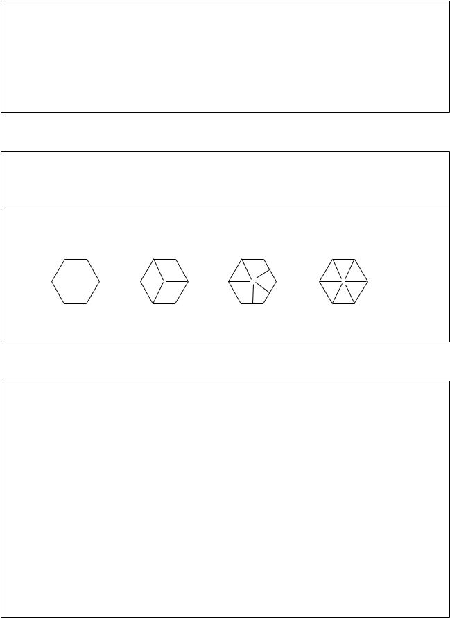
GENERAL INFORMATION |
|
|
27 |
|
|
|
|
|
|||
|
Table 5 FUEL TANK CAPACITY (continued) |
|
1 |
||
|
Gal. |
Liters |
|
|
|
|
|
|
|
||
|
|
|
|
|
|
1995-1996 models |
|
|
|
|
|
XLH883/XLH883 Hugger |
|
|
|
|
|
Total |
2.25 |
8.5 |
|
|
|
Reserve |
0.25 |
0.9 |
|
|
|
All other models |
|
|
|
|
|
Total |
3.30 |
12.5 |
|
|
|
Reserve |
0.50 |
1.8 |
|
|
|
1997-2003 models |
|
|
|
|
|
Total |
3.30 |
12.4 |
|
|
|
Reserve |
0.50 |
1.8 |
|
|
|
Table 6 GENERAL TORQUE RECOMMENDATIONS (ft.-lb.)1
Type2 |
1/4 |
5/16 |
3/8 |
7/16 |
1/2 |
9/16 |
5/8 |
3/4 |
7/8 |
1 |
SAE 2 |
6 |
12 |
20 |
32 |
47 |
69 |
96 |
155 |
206 |
310 |
SAE 5 |
10 |
19 |
33 |
54 |
78 |
114 |
154 |
257 |
382 |
587 |
SAE 7 |
13 |
25 |
44 |
71 |
110 |
154 |
215 |
360 |
570 |
840 |
SAE 8 |
14 |
29 |
47 |
78 |
119 |
169 |
230 |
380 |
600 |
700 |
1.Convert ft.-lb. specification to N•m by multiplying by 1.3558.
2.Fastener strength of SAE bolts can be determined by the bolt head grade markings. Unmarked bolt heads and cap screws are usually mild steel. More grade markings indicate higher fastener quality.
SAE 2 |
SAE 5 |
SAE 7 |
SAE 8 |
|
Table 7 CONVERSION FORMULAS |
|
Multiply: |
By: |
To get the equivalent of: |
|
|
|
Length |
|
|
Inches |
25.4 |
Millimeter |
Inches |
2.54 |
Centimeter |
Miles |
1.609 |
Kilometer |
Feet |
0.3048 |
Meter |
Millimeter |
0.03937 |
Inches |
Centimeter |
0.3937 |
Inches |
Kilometer |
0.6214 |
Mile |
Meter |
3.281 |
Feet |
Fluid volume |
|
|
U.S. quarts |
0.9463 |
Liters |
U.S. gallons |
3.785 |
Liters |
U.S. ounces |
29.573529 |
Milliliters |
Imperial gallons |
4.54609 |
Liters |
Imperial quarts |
1.1365 |
Liters |
Liters |
0.2641721 |
U.S. gallons |
Liters |
1.0566882 |
U.S. quarts |
Liters |
33.814023 |
U.S. ounces |
Liters |
0.22 |
Imperial gallons |
Liters |
0.8799 |
Imperial quarts |
Milliliters |
0.033814 |
U.S. ounces |
Milliliters |
1.0 |
Cubic centimeters |
Milliliters |
0.001 |
Liters |
|
|
(continued) |
28 |
|
CHAPTER ONE |
|
Table 7 CONVERSION FORMULAS continued) |
|
Multiply: |
By: |
To get the equivalent of: |
|
|
|
Torque |
|
|
Foot-pounds |
1.3558 |
Newton-meters |
Foot-pounds |
0.138255 |
Meters-kilograms |
Inch-pounds |
0.11299 |
Newton-meters |
Newton-meters |
0.7375622 |
Foot-pounds |
Newton-meters |
8.8507 |
Inch-pounds |
Meters-kilograms |
7.2330139 |
Foot-pounds |
Volume |
|
|
Cubic inches |
16.387064 |
Cubic centimeters |
Cubic centimeters |
0.0610237 |
Cubic inches |
Temperature |
|
|
Fahrenheit |
(°F Ð 32) × 0.556 |
Centigrade |
Centigrade |
(°C × 1.8) + 32 |
Fahrenheit |
Weight |
|
|
Ounces |
28.3495 |
Grams |
Pounds |
0.4535924 |
Kilograms |
Grams |
0.035274 |
Ounces |
Kilograms |
2.2046224 |
Pounds |
Pressure |
|
|
Pounds per square inch |
0.070307 |
Kilograms per |
|
|
square centimeter |
Kilograms per square |
14.223343 |
Pounds per square inch |
centimeter |
|
|
Kilopascals |
0.1450 |
Pounds per square inch |
Pounds per square inch |
6.895 |
Kilopascals |
Speed |
|
|
Miles per hour |
1.609344 |
Kilometers per hour |
Kilometers per hour |
0.6213712 |
Miles per hour |
|
|
|
|
Table 8 TECHNICAL ABBREVIATIONS |
|
|
|
|
A |
|
Ampere |
AC |
|
Alternating current |
A• h |
|
Ampere hour |
C |
|
Celsius |
cc |
|
Cubic centimeter |
CDI |
|
Capacitor discharge ignition |
cm |
|
Centimeter |
cu. in. |
|
Cubic inch and cubic inches |
cyl. |
|
Cylinder |
DC |
|
Direct current |
F |
|
Fahrenheit |
fl. oz. |
|
Fluid ounces |
ft. |
|
Foot |
ft.-lb. |
|
Foot pounds |
gal. |
|
Gallon and gallons |
hp |
|
Horsepower |
Hz |
|
Hertz |
in. |
|
Inch and inches |
in.-lb. |
|
Inch-pounds |
in. Hg |
|
Inches of mercury |
kg |
|
Kilogram |
kg/cm2 |
|
Kilogram per square centimeter |
kgm |
|
Kilogram meter |
km |
|
Kilometer |
km/h |
|
Kilometer per hour |
kPa |
|
Kilopascals |
kW |
|
Kilowatt |
L |
|
Liter and liters |
L/m |
|
Liters per minute |
lb. |
|
Pound and pounds |
m |
|
Meter |
MAP |
|
Manifold absolute pressure |
|
|
(continued) |
|
|
|
GENERAL INFORMATION |
|
|
|
29 |
|
|
|
|
|
|
|
|
|||
|
|
Table 8 TECHNICAL ABBREVIATIONS (continued) |
|
|
1 |
||
mL |
|
|
Milliliter |
|
|
|
|
|
|
|
|
|
|
||
mm |
|
|
Millimeter |
|
|
|
|
MPa |
|
|
Megapascal |
|
|
|
|
N |
|
|
Newton |
|
|
|
|
N• m |
|
|
Newton meter |
|
|
|
|
oz. |
|
|
Ounce and ounces |
|
|
|
|
p |
|
|
Pascal |
|
|
|
|
psi |
|
|
Pounds per square inch |
|
|
|
|
pt. |
|
|
Pint and pints |
|
|
|
|
qt. |
|
|
Quart and quarts |
|
|
|
|
rpm |
|
|
Revolution per minute |
|
|
|
|
TDC |
|
|
Top dead center |
|
|
|
|
V |
|
|
Volt |
|
|
|
|
VAC |
|
|
Alternating current voltage |
|
|
|
|
VDC |
|
|
Direct current voltage |
|
|
|
|
W |
|
|
Watt |
|
|
|
|
|
|
|
|
|
|
||
|
|
Table 9 AMERICAN TAP AND DRILL SIZES |
|
|
|
||
|
|
|
|
|
|
|
|
Tap thread |
|
Drill size |
Tap thread |
Drill size |
|
|
|
|
|
|
|
|
|
|
|
#0-80 |
|
3/64 |
1/4-28 |
No. 3 |
|
|
|
#1-64 |
|
No. 53 |
5/16-18 |
F |
|
|
|
#1-72 |
|
No. 53 |
5/16-24 |
I |
|
|
|
#2-56 |
|
No. 51 |
3/8-16 |
5/16 |
|
|
|
#2-64 |
|
No. 50 |
3/8-24 |
Q |
|
|
|
#3-48 |
|
5/64 |
7/16-14 |
U |
|
|
|
#3-56 |
|
No. 46 |
7/16-20 |
W |
|
|
|
#4-40 |
|
No. 43 |
1/2-13 |
27/64 |
|
|
|
#4-48 |
|
No. 42 |
1/2-20 |
29/64 |
|
|
|
#5-40 |
|
No. 39 |
9/16-12 |
31/64 |
|
|
|
#5-44 |
|
No. 37 |
9/16-18 |
33/64 |
|
|
|
#6-32 |
|
No. 36 |
5/8-11 |
17/32 |
|
|
|
#6-40 |
|
No. 33 |
5/18-18 |
37/64 |
|
|
|
#8-32 |
|
No. 29 |
3/4-10 |
21/32 |
|
|
|
#8-36 |
|
No. 29 |
3/4-16 |
11/16 |
|
|
|
#10-24 |
|
No. 25 |
7/8-9 |
49/64 |
|
|
|
#10-32 |
|
No. 21 |
7/8-14 |
13/16 |
|
|
|
#12-24 |
|
No. 17 |
1-8 |
7/8 |
|
|
|
#12-28 |
|
No. 15 |
1-14 |
15/16 |
|
|
|
1/4-20 |
|
No. 8 |
|
|
|
|
|
|
|
|
|
|
|
||
|
|
Table 10 METRIC TAP AND DRILL SIZES |
|
|
|
||
Metric |
Drill |
|
Decimal |
|
|
|
|
size |
equivalent |
fraction |
Nearest fraction |
|
|
|
|
|
|
|
|
|
|
|
|
3 × 0.50 |
No. 39 |
|
0.0995 |
3/32 |
|
|
|
3 × 0.60 |
3/32 |
|
0.0937 |
3/32 |
|
|
|
4 × 0.70 |
No. 30 |
|
0.1285 |
1/8 |
|
|
|
4 × 0.75 |
1/8 |
|
0.125 |
1/8 |
|
|
|
5 × 0.80 |
No. 19 |
|
0.166 |
11/64 |
|
|
|
5 × 0.90 |
No. 20 |
|
0.161 |
5/32 |
|
|
|
6 × 1.00 |
No. 9 |
|
0.196 |
13/64 |
|
|
|
7 × 1.00 |
16/64 |
|
0.234 |
15/64 |
|
|
|
8 × 1.00 |
J |
|
0.277 |
9/32 |
|
|
|
8 × 1.25 |
17/64 |
|
0.265 |
17/64 |
|
|
|
9 × 1.00 |
5/16 |
|
0.3125 |
5/16 |
|
|
|
9 × 1.25 |
5/16 |
|
0.3125 |
5/16 |
|
|
|
10 × 1.25 |
11/32 |
|
0.3437 |
11/32 |
|
|
|
10 × 1.50 |
R |
|
0.339 |
11/32 |
|
|
|
11 × 1.50 |
3/8 |
|
0.375 |
3/8 |
|
|
|
12 × 1.50 |
13/32 |
|
0.406 |
13/32 |
|
|
|
12 × 1.75 |
13/32 |
|
0.406 |
13/32 |
|
|
|
|
|
|
|
|
|
|
|
30 |
|
|
|
|
|
CHAPTER ONE |
|
Table 11 DECIMAL AND METRIC EQUIVALENTS |
|
||||
|
Decimal |
Metric |
|
|
Decimal |
Metric |
Fractions |
in. |
mm |
|
Fractions |
in. |
mm |
|
|
|
|
|
|
|
1/64 |
0.015625 |
0.39688 |
|
33/64 |
0.515625 |
13.09687 |
1/32 |
0.03125 |
0.79375 |
|
17/32 |
0.53125 |
13.49375 |
3/64 |
0.046875 |
1.19062 |
|
35/64 |
0.546875 |
13.89062 |
1/16 |
0.0625 |
1.58750 |
|
9/16 |
0.5625 |
14.28750 |
5/64 |
0.078125 |
1.98437 |
|
37/64 |
0.578125 |
14.68437 |
3/32 |
0.09375 |
2.38125 |
|
19/32 |
0.59375 |
15.08125 |
7/64 |
0.109375 |
2.77812 |
|
39/64 |
0.609375 |
15.47812 |
1/8 |
0.125 |
3.1750 |
|
5/8 |
0.625 |
15.87500 |
9/64 |
0.140625 |
3.57187 |
|
41/64 |
0.640625 |
16.27187 |
5/32 |
0.15625 |
3.96875 |
|
21/32 |
0.65625 |
16.66875 |
11/64 |
0.171875 |
4.36562 |
|
43/64 |
0.671875 |
17.06562 |
3/16 |
0.1875 |
4.76250 |
|
11/16 |
0.6875 |
17.46250 |
13/64 |
0.203125 |
5.15937 |
|
45/64 |
0.703125 |
17.85937 |
7/32 |
0.21875 |
5.55625 |
|
23/32 |
0.71875 |
18.25625 |
15/64 |
0.234375 |
5.95312 |
|
47/64 |
0.734375 |
18.65312 |
1/4 |
0.250 |
6.35000 |
|
3/4 |
0.750 |
19.05000 |
17/64 |
0.265625 |
6.74687 |
|
49/64 |
0.765625 |
19.44687 |
9/32 |
0.28125 |
7.14375 |
|
25/32 |
0.78125 |
19.84375 |
19/64 |
0.296875 |
7.54062 |
|
51/64 |
0.796875 |
20.24062 |
5/16 |
0.3125 |
7.93750 |
|
13/16 |
0.8125 |
20.63750 |
21/64 |
0.328125 |
8.33437 |
|
53/64 |
0.828125 |
21.03437 |
11/32 |
0.34375 |
8.73125 |
|
27/32 |
0.84375 |
21.43125 |
23/64 |
0.359375 |
9.12812 |
|
55/64 |
0.859375 |
22.82812 |
3/8 |
0.375 |
9.52500 |
|
7/8 |
0.875 |
22.22500 |
25/64 |
0.390625 |
9.92187 |
|
57/64 |
0.890625 |
22.62187 |
13/32 |
0.40625 |
10.31875 |
|
29/32 |
0.90625 |
23.01875 |
27/64 |
0.421875 |
10.71562 |
|
59/64 |
0.921875 |
23.41562 |
7/16 |
0.4375 |
11.11250 |
|
15/16 |
0.9375 |
23.81250 |
29/64 |
0.453125 |
11.50937 |
|
61/64 |
0.953125 |
24.20937 |
15/32 |
0.46875 |
11.90625 |
|
31/32 |
0.96875 |
24.60625 |
31/64 |
0.484375 |
12.30312 |
|
63/64 |
0.984375 |
25.00312 |
1/2 |
0.500 |
12.70000 |
|
1 |
1.00 |
25.40000 |
|
|
|
|
|
|
|
|
|
Table 12 SPECIAL TOOLS |
|
|
||
Tool description |
|
|
Part No. |
|
Manufacturer |
|
|
|
|
|
|
|
|
Bearing installation tool handle |
|
33416-80 |
|
JIMS |
||
Belt tension gauge |
|
|
HD-35381-A |
|
H-D |
|
Breakout box |
|
|
HD-42682 |
|
H-D |
|
Breakout box adapters |
|
HD-42962 |
|
H-D |
||
Bushing reamer tool |
|
1726-2 |
|
JIMS |
||
Clutch spring compression tool |
|
34761-84 |
|
JIMS |
||
Clutch spring compression tool |
|
38515-90/91 |
|
JIMS |
||
Clutch spring compression tool |
|
HD-38515A |
|
H-D |
||
Connecting rod bushing hone |
|
HD-35102 |
|
H-D |
||
Connecting rod bushing tool |
|
95970-32C |
|
JIMS |
||
Connecting rod clamp tool |
|
1284 |
|
JIMS |
||
Countershaft support plate |
|
HD-37404 |
|
H-D |
||
Fork oil gauge |
|
|
HD-59000A |
|
H-D |
|
Fork seal driver |
|
|
HD-36583 |
|
H-D |
|
Fork spring compressor (1200S models) |
|
HD-41549A |
|
H-D |
||
Fork spring plate tool |
|
HD-41551 |
|
H-D |
||
Hose clamp pliers |
|
|
HD-97087-65B |
|
H-D |
|
Ignition system harness test kit |
|
HD-41404 |
|
H-D |
||
Main drive gear needle bearing installation tool |
|
|
|
|
||
1991-1994 models |
|
|
HD-37842 |
|
H-D |
|
1995-2003 models |
|
|
HD-37842A |
|
H-D |
|
Main drive gear remover and installer |
|
HD-35316-A |
|
H-D |
||
Multimeter |
|
|
HD-35500 |
|
H-D |
|
Neway valve seat cutter set |
|
HD-35758-B |
|
H-D |
||
|
|
|
|
(continued) |
|
|
|
|
|
|
|
|
|
Loading...