


20 ton Log Splitter

Owner’s Manual & Safety Instructions
Save This Manual Keep this manual for the safety warnings and precautions, assembly,
operating, inspection, maintenance and cleaning procedures. Write the product’s serial number in the
back of the manual near the assembly diagram (or month and year of purchase if product has no number).
Keep this manual and the receipt in a safe and dry place for future reference.
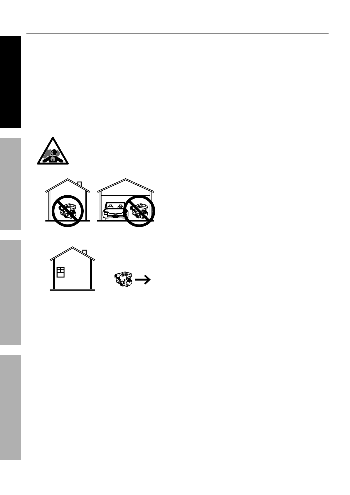
Using an engine indoors
CAN KILL YOU IN MINUTES.
Engine exhaust contains carbon monoxide.
This is a poison you cannot see or smell.
NEVER use inside
a home or garage,
EVEN IF doors and
windows are open.
Email our technical support at: productsupport@harborfreight.com
REV 14k
When unpacking, make sure that the product is intact
and undamaged. If any parts are missing or broken,
please call 1-888-866-5797 as soon as possible.
Copyright© 2013 by Harbor Freight Tools®. All rights reserved.
No portion of this manual or any artwork contained herein may be reproduced in
any shape or form without the express written consent of Harbor Freight Tools.
Diagrams within this manual may not be drawn proportionally. Due to continuing
improvements, actual product may differ slightly from the product described herein.
Tools required for assembly and service may not be included.
Only use OUTSIDE
and far away from
windows, doors,
and vents.
Visit our website at: http://www.harborfreight.com
Read this material before using this product.
Failure to do so can result in serious injury.
SAVE THIS MANUAL.

Table of Contents
Specifications ............................................. 2
Safety ......................................................... 3
Setup .......................................................... 7
SAFETY OPERATION MAINTENANCESETUP
Operation ................................................... 11
Specifications
Log Splitter Specifications
Ram Travel 21.85"
Log Capacity 23.6" L x 16" Diameter
Towing
Hitch Ball Size 2"
Hydraulic Fluid Reservoir 2.25 gallons (8.5 L)
Type of Hydraulic Fluid
Wheel Size 15.5" x 4"
Tire Size 4.80-8
Required Tire Air Pressure 60 PSI, Cold
Weight 378 lb (lled with uid)
Maintenance .............................................. 18
Troubleshooting ......................................... 22
Warranties ................................................. 24
Parts Lists and Diagrams .......................... 28
For off-road use only (not DOT approved);
maximum speed 45 mph
10W AW32, ASLE H-150 or
ISO32 Hydraulic Fluid
Engine Specifications
Displacement 212 cc
Engine Type
Cooling System Forced air cooled
Fuel
Engine Oil
Run Time @ 50% Load
with full tank
Sound Level at 22 feet 104 dB
Bore x Stroke 70 mm x 55 mm
Compression Ratio 8.5:1
Rotation viewed from PTO
(power takeoff - the output shaft)
Spark Plug
Valve Clearance
Speed Idle 1800 ± 50 RPM
Horizontal Single Cylinder
4-stroke OHV
Meets EPA phase III
emissions standards
Type 87+ octane unleaded gasoline
Capacity 0.9 Gallon (3.6 Liter)
Type SAE
Capacity 0.5 Quart
Type
Gap 0.7 – 0.8 mm
Intake 0.10 – 0.15 mm
Exhaust 0.15 – 0.20 mm
10W-30 above 32° F
5W-30 at 32° F or below
3 hr.
Counterclockwise
NGK® BP-6ES
NHSP® / Torch® F6TC
The emissions control system for this Engine is warranted for standards set by the
U.S. Environmental Protection Agency. For warranty information, refer to the last pages of this manual.
Page 2 For technical questions, please call 1-888-866-5797. ITEM 61594
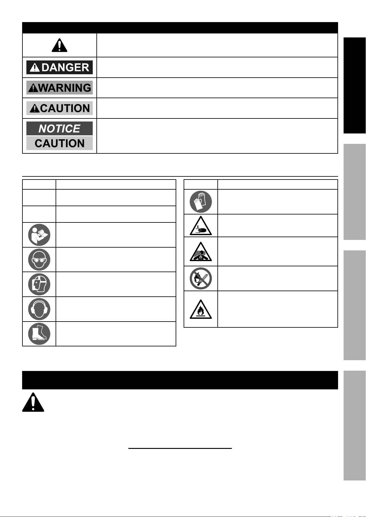
Symbol Definitions
WARNING SYMBOLS AND DEFINITIONS
This is the safety alert symbol. It is used to alert you to potential
personal injury hazards. Obey all safety messages that
follow this symbol to avoid possible injury or death.
Indicates a hazardous situation which, if not avoided,
will result in death or serious injury.
Indicates a hazardous situation which, if not avoided,
could result in death or serious injury.
Indicates a hazardous situation which, if not avoided,
could result in minor or moderate injury.
Addresses practices not related to personal injury.
SAFETYOPERATIONMAINTENANCE SETUP
Symbol Property or Statement
RPM
HP
Revolutions Per Minute
Horsepower
Read the manual before
set-up and/or use.
WARNING marking concerning
Risk of Eye Injury. Wear ANSI-approved
safety goggles with side shields.
WARNING marking concerning Risk of
Facial Injury from flying debris. Wear
ANSI-approved full face shield.
WARNING marking concerning
Risk of Hearing Loss.
Wear hearing protection.
WARNING marking concerning Risk of
Foot Injury. Wear steel-toe work boots.
Symbol Property or Statement
WARNING marking concerning
Risk of Hand Injury. Wear
heavy-duty work gloves.
WARNING marking concerning
Crushing Hazard. Keep hands and
feet away from moving parts.
WARNING marking concerning
Risk of Respiratory Injury.
Operate engine OUTSIDE and far away
from windows, doors, and vents.
WARNING marking concerning
Risk of Fire while handling fuel.
Do not smoke while handling fuel.
WARNING marking concerning
Risk of Fire.
Do not refuel while operating.
Keep flammable objects
away from engine.
IMPORTANT SAFETY INSTRUCTIONS
WARNING! Read all instructions.
Failure to follow all instructions listed below may result in fire, serious injury and/or DEATH.
The warnings and precautions discussed in this manual cannot cover all possible conditions and
situations that may occur. It must be understood by the operator that common sense and caution
are factors which cannot be built into this product, but must be supplied by the operator.
SAVE THESE INSTRUCTIONS
Page 3For technical questions, please call 1-888-866-5797.ITEM 61594
Set Up Precautions
1. Gasoline fuel and fumes are flammable, and
potentially explosive. Use proper fuel storage
and handling procedures. Do not store fuel
SAFETY OPERATION MAINTENANCESETUP
or other flammable materials nearby.
2. Have multiple ABC class fire extinguishers nearby.
3. Operation of this equipment may create sparks that
can start fires around dry vegetation.
A spark arrestor may be required. The operator
should contact local fire agencies for laws or
regulations relating to fire prevention requirements.
Operating Precautions
1. CARBON MONOXIDE HAZARD
Using an engine indoors
CAN KILL YOU IN MINUTES.
Engine exhaust contains
carbon monoxide. This is a poison
you cannot see or smell.
NEVER use inside a home or garage,
EVEN IF doors and windows are open.
Only use OUTSIDE and far away from windows,
doors, and vents.
2. Keep children away from the equipment,
especially while it is operating.
3. DO NOT OPERATE WITH ANY GUARD
DISABLED, DAMAGED, OR REMOVED. Keep
guards in place and in good working order.
4. Wear ANSI-approved safety goggles under
full face shield, heavy-duty work gloves
and steel-toe work boots during use.
5. Keep clear of moving parts and log
during operation. Crushing hazard.
6. Do not check for hydraulic leak with hands.
High-pressure fluid can be forced under the skin
resulting in serious injury. Inspect hydraulic lines
for leakage before use; do not use if leaks found.
7. Do not split wood containing foreign
objects (nails, for example).
4. Set up and operate only in a well-ventilated
area on a level, dry and solid surface
with wheels chocked.
5. Wear ANSI-approved safety goggles, heavy-duty
work gloves, and dust mask/respirator during set up.
6. Use only lubricants and fuel recommended
in the Specifications chart of this manual.
8. Do not use Splitter on logs longer than
23.6" or with a diameter greater than 8".
9. Hold the rounded, bark side of logs when
loading or positioning, never the ends. Do
not place hands or any body parts between
a log and any part of the Log Splitter.
10. Do not load or unload logs while
the splitter wedge is moving.
11. Do not split logs across the grain. Doing so will
damage the Log Splitter and could cause pieces of
log to be thrown, injuring the operator or bystanders.
12. Do not split more than one log at a time. A
piece of log can unexpectedly be thrown from
the machine, causing severe personal injury.
13. Remove split logs away from the Log
Splitter immediately. Split logs left near
the Log Splitter are a tripping hazard.
14. Do not tow the Log Splitter on roads or highways.
This product is not D.O.T. compliant.
15. Keep bystanders away during operation.
16. Fire Hazard! Do not fill gas tank while engine is
running. Do not operate if gasoline has been spilled.
Clean spilled gasoline before starting engine.
Do not operate near pilot light or open flame.
17. Do not touch engine during use.
Let engine cool down after use.
18. Never store fuel or other flammable
materials near the engine.
19. Industrial applications must follow
OSHA requirements.
20. Do not leave the equipment unattended when it is
running. Turn off the equipment (and remove safety
keys, if available) before leaving the work area.
21. The equipment can produce high noise levels.
Prolonged exposure to noise levels
above 85 dBA is hazardous to hearing.
Wear ear protection when operating the equipment
or when working nearby while it is operating.
Page 4 For technical questions, please call 1-888-866-5797. ITEM 61594

Operating Precautions (continued)
22. People with pacemakers should consult their
physician(s) before use. Electromagnetic fields in
close proximity to a heart pacemaker could cause
pacemaker interference or pacemaker failure.
Caution is necessary when near the
engine’s magneto or recoil starter.
23. Use only accessories that are recommended
by Harbor Freight Tools for your model.
Accessories that may be suitable for one
piece of equipment may become hazardous
when used on another piece of equipment.
24. Do not operate in explosive atmospheres,
such as in the presence of flammable
liquids, gases, or dust. Gasoline-powered
engines may ignite the dust or fumes.
25. Stay alert, watch what you are doing and use
common sense when operating this piece of
equipment. Do not use while tired or under the
influence of drugs, alcohol or medication.
26. Do not overreach. Keep proper footing and
balance at all times. This enables better control
of the equipment in unexpected situations.
27. Use this equipment with both hands only.
Using equipment with only one hand
can easily result in loss of control.
28. Dress properly. Do not wear loose clothing or
jewelry. Keep hair, clothing and gloves away
from moving parts. Loose clothes, jewelry or
long hair can be caught in moving parts.
29. Parts, especially exhaust system components,
get very hot during use. Stay clear of hot parts.
30. Do not cover the equipment during operation.
31. Keep the equipment, engine, and
surrounding area clean at all times.
32. Use the equipment, accessories, etc., in
accordance with these instructions and in the
manner intended for the particular type of
equipment, taking into account the working
conditions and the work to be performed.
Use of the equipment for operations different from
those intended could result in a hazardous situation.
33. Do not operate the equipment with known
leaks in the engine’s fuel system.
34. WARNING: This product contains or, when
used, produces a chemical known to the State
of California to cause cancer and birth defects
or other reproductive harm. (California Health
& Safety Code § 25249.5, et seq.)
35. When spills of fuel or oil occur, they must be
cleaned up immediately. Dispose of fluids and
cleaning materials as per any local, state, or
federal codes and regulations. Store oil rags in
a bottom-ventilated, covered, metal container.
36. Keep hands and feet away from moving parts.
Do not reach over or across
equipment while operating.
37. Before use, check for misalignment or binding of
moving parts, breakage of parts, and any other
condition that may affect the equipment’s operation.
If damaged, have the equipment serviced
before using. Many accidents are caused
by poorly maintained equipment.
38. Use the correct equipment for the application.
Do not modify the equipment and do not use the
equipment for a purpose for which it is not intended.
SAFETYOPERATIONMAINTENANCE SETUP
Service Precautions
1. Before service, maintenance, or cleaning:
a. Turn the engine switch to its “OFF” position.
b. Allow the engine to completely cool.
c. Then, remove the spark plug cap
from the spark plug.
2. Keep all safety guards in place and in
proper working order. Safety guards include
muffler, air cleaner, mechanical guards,
and heat shields, among other guards.
3. Do not alter or adjust any part of the
equipment or its engine that is sealed by the
manufacturer or distributor. Only a qualified
service technician may adjust parts that may
increase or decrease governed engine speed.
4. Wear ANSI-approved safety goggles,
heavy-duty work gloves, and
dust mask/respirator during service.
5. Maintain labels and nameplates on the equipment.
These carry important information.
If unreadable or missing, contact
Harbor Freight Tools for a replacement.
6. Have the equipment serviced by a qualified repair
person using only identical replacement parts.
This will ensure that the safety of the equipment
is maintained. Do not attempt any service or
maintenance procedures not explained in this
manual or any procedures that you are uncertain
about your ability to perform safely or correctly.
7. Store equipment out of the reach of children.
8. Follow scheduled engine and
equipment maintenance.
Page 5For technical questions, please call 1-888-866-5797.ITEM 61594
Service Precautions (continued)
Refueling:
1. Do not smoke, or allow sparks, flames,
or other sources of ignition around the
SAFETY OPERATION MAINTENANCESETUP
equipment, especially when refuelling.
2. Do not refill the fuel tank while the
engine is running or hot.
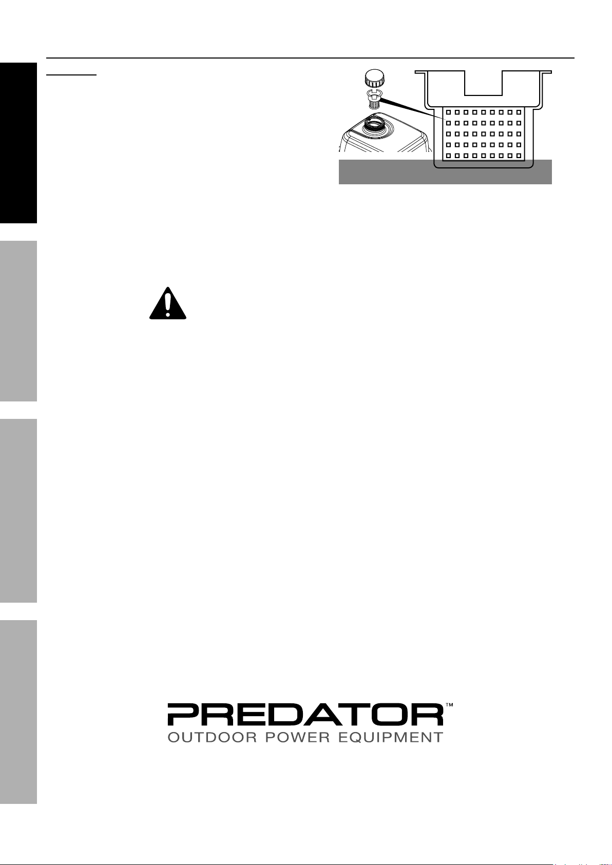
3. Do not fill fuel tank to the top.
Leave a little room for the fuel to expand as needed.
TO PREVENT FUEL LEAKAGE AND
FIRE HAZARD, do not fill fuel above
the bottom of fuel strainer.
SAVE THESE INSTRUCTIONS.
Max Fuel
DO NOT OVERFILL!
4. Refuel in a well-ventilated area only.
5. Wipe up any spilled fuel and allow excess
to evaporate before starting engine.
To prevent FIRE, do not start the engine
while the smell of fuel hangs in the air.
Page 6 For technical questions, please call 1-888-866-5797. ITEM 61594
Set Up
Read the ENTIRE IMPORTANT SAFETY
INFORMATION section at the beginning of this
manual including all text under subheadings
therein before set up or use of this product.
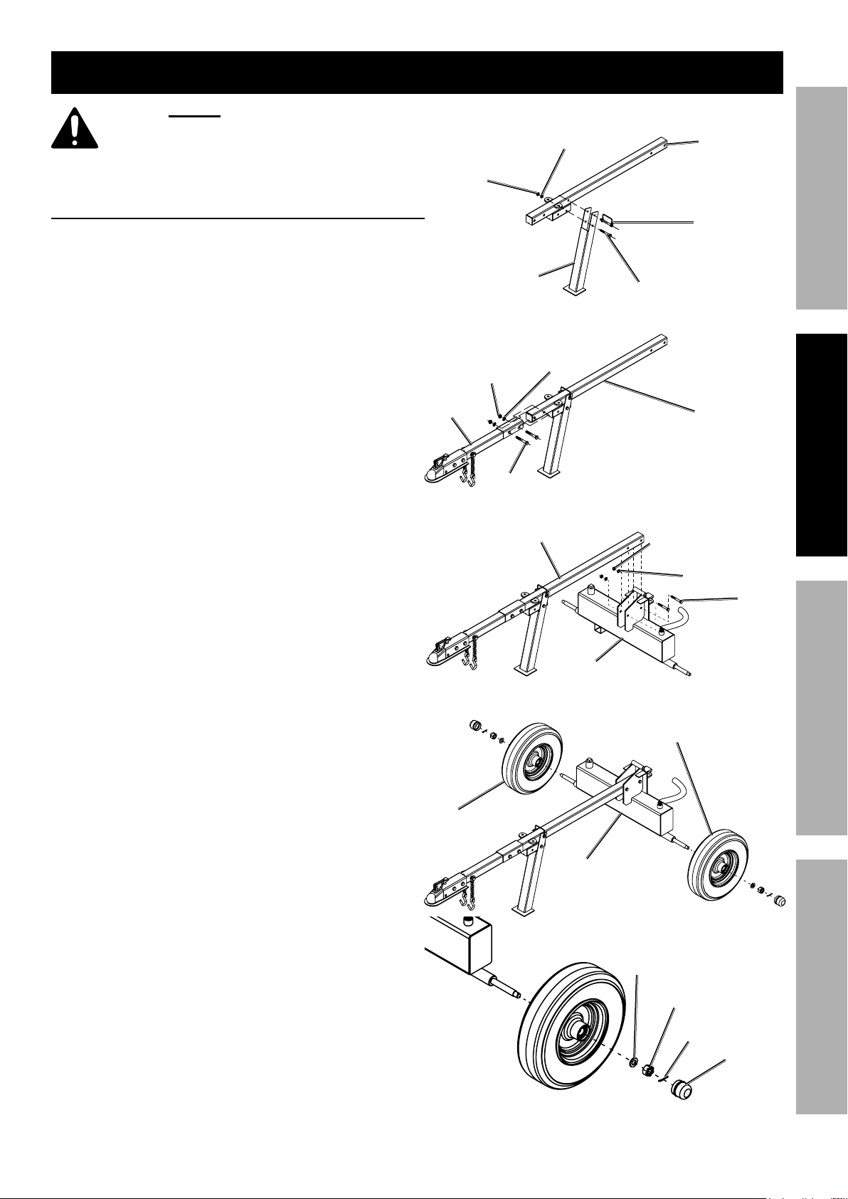
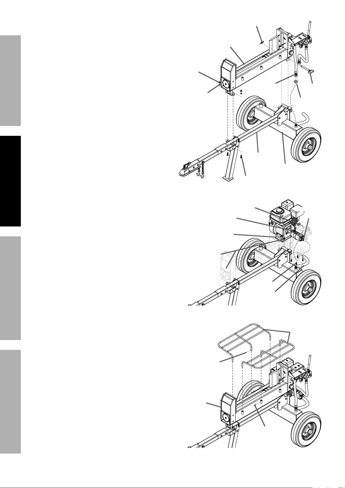
Assembly
1. Use Bolt (15) and Lock Pin (16) to attach the
Support Leg (14) underneath the Tow Bar (42).
Secure the Bolt using Washer (8) and Lock Nut (5)
and secure the Lock Pin using its clip.
Lock Nut (5)
Support Leg (14)
Assembly Step 1: Attach Support Leg
Bolt (15)
Tow Bar (42)Washer (8)
Lock Pin (16)
SAFETYOPERATIONMAINTENANCE SETUP
2. Attach Front Tow Bar (9) to end of Tow Bar using
Bolts (2), Washers (3), and Lock Nuts (4).
3. Attach Tow Bar to bracket on top of Fluid Tank (51)
using Bolts (2), Washers (3), and Lock Nuts (4).
4. Wheel Assembly:
Nut (4)
Front Tow
Bar (9)
Assembly Step 2: Attach Front Tow Bar
Lock
Washer (3)
Bolt (2)
Tow Bar
Tow Bar
Lock
Nut (4)
Washer (3)
Fluid
Tank (51)
Assembly Step 3: Attach Fluid Tank
Wheel (48)
Bolt (2)
a. Pack grease into the center of one
Wheel’s (48) hub from both sides.
b. Slide the Wheel onto an axle on the Fluid Tank.
c. Place a Washer (47), then
a Castle Nut (46) onto the axle.
d. Tighten the Castle Nut until the Wheel can spin
with slight resistance. Loosen the Castle Nut about
1/6 turn from the point resistance is felt,
and insert the Cotter Pin (74).
e. Bend the end of the Cotter Pin
back to lock it in place.
f. Press the Axle Cap (44) securely in place.
Wheel (48)
Fluid
Tank
Washer
(47)
Castle
Nut (46)
Cotter
Pin (74)
Axle
Cap (44)
Assembly Step 4: Attach Wheels
Page 7For technical questions, please call 1-888-866-5797.ITEM 61594
R-Pin (23)
5. Beam Assembly:
SAFETY OPERATION MAINTENANCESETUP
a. Place Beam (21) assembly on top of
the Fluid Tank and Tow Bar.
b. Line up the bracket underneath the
Beam with the tube at the top of the
Fluid Tank, and insert the Hinge Pin (41).
Secure the Hinge Pin with the R-Pin (23).
c. Secure the brackets at the front of
the Tow Bar together using Bolts (11),
Washers (3), and Lock Nuts (4).
d. Attach the O-Ring (34) and Hose (35) marked
“Fluid Tank” to the threaded connector at the top
of the Fluid Tank. Wrench-tighten it securely.
6. Engine and Pump Assembly:
a. Attach Engine Connecting Plate (58) to the pedestal
on the back of the Fluid Tank using Bolts (66),
Lock Washers (28), and Lock Nuts (61).
b. Slide a Hose Clamp (57) over the Return Hose (56).
Beam (21)
asm.
Lock
Nut (4)
Washer (3)
Bolt (11)
Assembly Step 5: Attach Beam Assembly
O-Ring (34)
Connector (72)
Engine
Connecting
Plate (58)
Hose
(35)
Tow Bar
Hinge
Pin (41)
O-Ring
(34)
Fluid
Tank
Fluid
Connector
(17)
c. Slip the Return Hose over the Fluid Connector (17).
d. Slide the Hose Clamp over the connection,
and tighten its screw to secure it in place.
e. Attach an O-Ring (34) to the Connector (72)
on the Hydraulic Pump (59). Connect the
unconnected Hose (38) marked “Pump” from
the Control Valve (32) to the Connector on the
Hydraulic Pump. Wrench-tighten it securely.
7. Insert the Log Cradles (73) into the brackets
on the sides of the Beam (21) angled outward.
Secure them in place with a Cotter Pin (45).
Bend the Cotter Pins back to secure them in place.
Lock Nut (61)
and
Lock Washer (28)
Bolt (66)
Return
Hose (56)
Assembly Step 6: Attach Engine and Pump
Log
Cradles (73)
Cotter
Pin (45)
Beam (21)
Cotter
Pin (45)
Assembly Step 7: Attach Log Cradles
Page 8 For technical questions, please call 1-888-866-5797. ITEM 61594
High Altitude Operation Above 3000 feet
WARNING! TO PREVENT SERIOUS INJURY FROM FIRE:
Follow instructions in a well-ventilated area away from ignition sources.
If the engine is hot from use, shut the engine off and wait for it to cool before proceeding. Do not smoke.
NOTICE: Warranty void if necessary adjustments are not made for high altitude use.
At high altitudes, the engine’s carburetor, governor (if so equipped), and any other parts that control the fuel-air
ratio will need to be adjusted by a qualified mechanic to allow efficient high-altitude use and to prevent damage
to the engine and any other devices used with this product. The fuel system on this engine may be influenced by
operation at higher altitudes. Proper operation can be ensured by installing an altitude kit at altitudes higher than
3000 feet above sea level. At elevations above 8000 feet, the engine may experience decreased performance, even
with the proper main jet. Operating this engine without the proper altitude kit installed may increase the engine’s
emissions and decrease fuel economy and performance. The kit should be installed by a qualified mechanic.
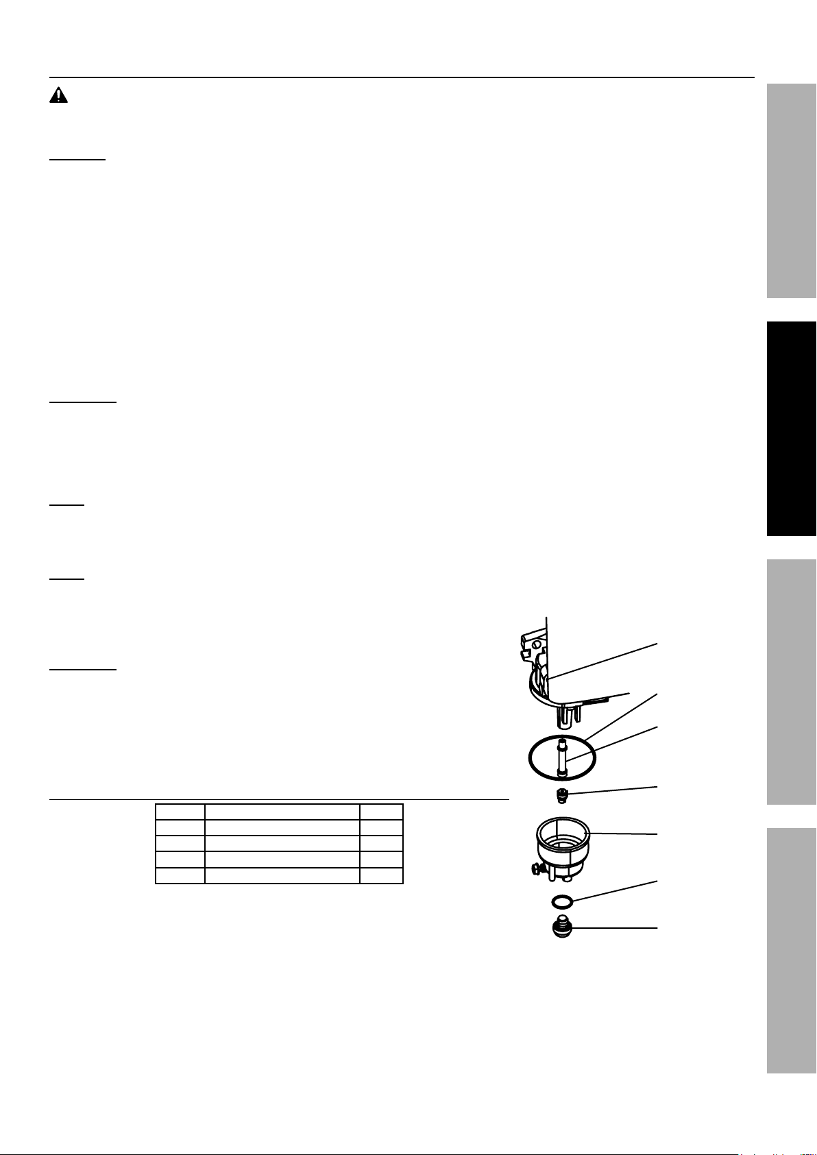
1. Turn off the engine.
2. Close the fuel valve.
3. Place a bowl under the fuel cup to catch any spilled fuel.
CAUTION! Carburetor bowl may have gas in it which will leak upon removing the bolt.
4. Unthread the bolt holding the fuel cup.
5. Remove the bolt, Bolt Seal, fuel cup, Fuel Cup Seal and Main Jet from the body of the carburetor assembly.
A carburetor screwdriver (not included) is needed to remove and install the Main Jet.
SAFETYOPERATIONMAINTENANCE SETUP
Note: The mixing tube is held in place by the Main Jet and might fall out when it is removed.
If it falls out, replace it in the same orientation before replacing the Main Jet.
6. Replace the Main Jet with the replacement Main Jet needed for your altitude range (part 1a or 2a).
Note: The Fuel Cup Seal and Bolt Seal may be damaged during removal
and should be replaced with the new ones from the kit.
7. Replace the Fuel Cup Seal (4a), fuel cup,
Bolt Seal (3a), and bolt. Tighten in place.
CAUTION: Do not cross thread bolt when tightening.
Finger tighten first and then use a wrench to
make sure the bolt is properly threaded.
8. Wipe up any spilled fuel and allow excess to evaporate
before starting engine. To prevent FIRE, do not start
the engine while the smell of fuel hangs in the air.
High Altitude Kit Parts List - A
Part Description Qty
1a Main Jet 3000-6000 ft. 1
2a Main Jet 6000-8000 ft. 1
3a Bolt Seal 1
4a Fuel Cup Seal 1
Carburetor
Assembly
Fuel Cup Seal
Mixing Tube
(might remain
inside carburetor)
Main Jet
Fuel Cup
Bolt Seal
Bolt
Page 9For technical questions, please call 1-888-866-5797.ITEM 61594
TO PREVENT SERIOUS INJURY:
Operate only with proper spark arrestor installed.
Operation of this equipment may create sparks that can start fires around dry vegetation.
SAFETY OPERATION MAINTENANCESETUP
A spark arrestor may be required.
The operator should contact local fire agencies for laws or regulations
relating to fire prevention requirements.
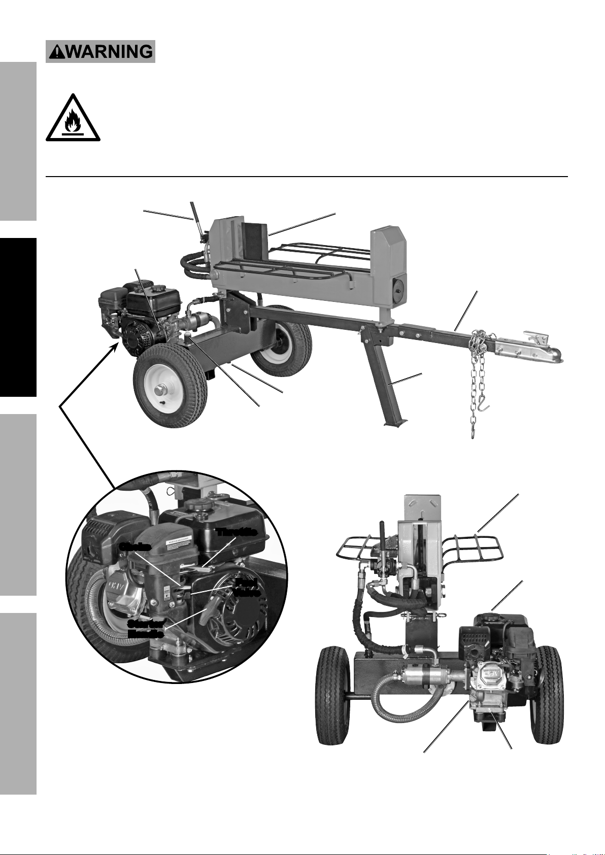
Components and Controls
Control
Handle
Engine
Switch
Cutting Wedge
Tow Bar
Support
Leg
Fluid Drain Plug
Fluid Fill Plug
Log Cradle
Throttle
Choke
Fuel
Valve
Starter
Handle
Dipstick
Page 10 For technical questions, please call 1-888-866-5797. ITEM 61594
Fuel Cap
Oil Drain
Plug
 Loading...