


COMPACT Bench BENDER
Model 38471
Assembly Instructions and Project ideas
Diagrams within this manual may not be drawn proportionally.
Due to continuing improvements, actual product may differ slightly from the product described herein.
Distributed exclusively by Harbor Freight Tools®.
3491 Mission Oaks Blvd., Camarillo, CA 93011
Visit our website at: http://www.harborfreight.com
Read this material before using this product. Failure to do so can result in serious injury. Save this manual.
Copyright© 2000 by Harbor Freight Tools®. All rights reserved. No portion of this manual or any artwork contained herein may be reproduced in any shape or form without the express written consent of Harbor Freight Tools.
For technical questions or replacement parts, please call 1-800-444-3353.

THANK YOU for choosing a HARBOR FREIGHT TOOLS product. For future reference, please complete the owner’s record below:
Model___________ |
Serial No._____________ |
Purchase Date_____________ |
Save This Manual
You will need the manual for the safety warnings and precautions, assembly instructions, operating and maintenance procedures, parts list and diagram. Keep your invoice with this manual. Write the invoice number on the inside of the front cover. Keep the manual and invoice in a safe and dry place for future reference.
|
Technical Specifications |
Tool Name: |
Compact Bender-Bench |
Item Number: |
38471 |
Dimensions: |
10-1/8” W x 9-1/8” H x 53” L |
Stand: |
.3000” Steel, 4-1/2” High |
Mounting Holes: |
(4) ½” |
Max. Width of Stock: |
1-15/16” |
Max. Stock Thickness: |
5/16” |
Max. Bar Stock Diameter: |
5/8” |
Dies: |
1”, 1-1/4”, 1-1/2”, 1-3/4”, 2”, 2-1/2”, 3” |
Tool Weight: |
37.5 LBS. |
Safety Warnings and Precautions
WARNING: When using tool, basic safety precautions should always be followed to reduce the risk of personal injury and damage to equipment.
Read all instructions before using this product!
1.Avoid working alone. If an accident happens, an assistant can bring help.
2.Keep work area clean. Cluttered areas invite injuries.
3.Observe work area conditions. Keep work area well lighted.
4.Keep children away. Children must never be allowed in the work area. Do not let them handle machines, tools, or extension cords.
5.Store idle equipment. When not in use, tools must be stored in a dry location to inhibit rust. Always lock up tools and keep out of reach of children.
6.Dress properly. Do not wear loose clothing or jewelry as they can be caught in moving parts. Protective, electrically nonconductive clothes and nonskid footwear are recommended when working. Wear restrictive hair covering to contain long hair.
7.Use eye and ear protection. Always wear ANSI approved impact safety goggles.
8.Do not overreach. Keep proper footing and balance at all times.
9.Use the right tool for the job. Do not attempt to force a small tool or attachment to do the work of a larger industrial tool. There are certain applications for which this tool was designed. Do not modify this tool and do not use this tool for a purpose for which it was not intended.
SKU 38471 |
For technical questions, please call 1-800-444-3353. |
Page 2 |
10.Stay alert. Watch what you are doing, use common sense. Do not operate any tool when you are tired.
11.Check for damaged parts. Before using any tool, any part that appears damaged should be carefully checked to determine that it will operate properly and perform its intended function. Check for alignment and binding of moving parts; any broken parts or mounting fixtures; and any other condition that may affect proper operation. Any part that is damaged should be properly repaired or replaced by a qualified technician. Do not use the tool if any switch does not turn On and Off properly.
12.Replacement parts and accessories. When servicing, use only identical replacement parts. Use of any other parts will void the warranty. Only use accessories intended for use with this tool. Approved accessories are available from Harbor Freight Tools.
13.Do not operate tool if under the influence of alcohol or drugs. Read warning labels on prescriptions to determine if your judgment or reflexes are impaired while taking drugs. If there is any doubt, do not operate the tool.
14.Maintenance. For your safety, maintenance should be performed regularly by a qualified technician.
Warning: The warnings, cautions, and instructions discussed in this instruction manual cannot cover all possible conditions and situations that may occur. It must be understood by the operator that common sense and caution are factors which cannot be built into this product, but must be supplied by the operator.
Warning: Welding Precautions
If you perform any welding using the materials that have been bent by this tool, it is important that you remember that there are additional safety precautions that must be taken. Of course, you should follow all warnings and instructions provided by the manufacturer of the welding equipment used.
Be aware of flying sparks. Only weld in an area that does not contain any materials which can be ignited by flying sparks. Extinguish any significant flying sparks before continuing to weld.
Protect yourself and others around you from burns which can be caused by flying sparks.
Make certain that you have a fire extinguisher accessible.
Never weld in an atmosphere which might contain flammable fumes.
Periodically during welding, and after completion of a job, inspect your area for any ignition which may have been caused by flying sparks.
Never leave your welder unattended while it is plugged in.
Always wear electrical insulating clothing, gloves and shoes while using your welder.
Flying sparks can cause injury, and hot materials can cause burns. Please wear appropriate safety clothing, and observe precautions to prevent burns or injury to yourself or others.
Wear protective clothing such as heavy gloves, apron and boots.
Do not look directly into the welding arc without appropriate protective eye shields.
Do not allow others to look directly into the arc without appropriate eye protection.
Wear protective gloves while welding. Welding causes the metal to become very hot, which can cause burns. Do not touch welded areas until you are certain they have completely cooled.
Do not place weld materials where others can touch them, or where they can cause a fire.
SKU 38471 |
For technical questions, please call 1-800-444-3353. |
Page 3 |

Warning: Welding Precautions (Continued)
The electrode, and especially the welding rods become very hot during welding. Exercise extreme caution to prevent burns to yourself or others.
Note: Read and adhere to all warnings and instructions in the instruction manual provided by the manufacturer of the welder being used.
Assembly
Your Compact Bender-Bench will require complete assembly prior to operation. It is important that you read the entire manual to become familiar with the unit BEFORE you use the Compact Bender. Before assembling your Compact Bender be sure that you have all parts described in the Parts List on page 9.
When assembling your Compact Bender-Bench, it will be helpful to refer to each of the operational Figures as well as to the Parts List and Assembly Diagrams on pages 9-11.
Mounting Surface: The mounting surface must be flat, level and capable of supporting the weight of the Compact Bender combined with the materials to be worked with.
Step 1) |
Bolt the Stand (#11) to a flat, stable surface such as a workbench that is capable of supporting |
|
the weight of this tool and the various workpieces to be used. |
Step 2) |
Place the three (3) Mounting Spacers (#13) over each hole on the top of the Stand (#11)-see |
|
Figure 1. |
Mounting
|
Figure 1-Assembly |
Step 3) |
Place the Ring Assembly/Die Receiver (#10) over the three Mounting Spacers (#13) so that the |
|
two holes on the Ring Assembly (#10) line up with the corresponding Mounting Spacers (#13). |
|
Insert two (2) Mounting Bolts (#16) through the Ring Assembly (#10), Mounting Spacer (#13) |
|
and Stand (#11). Tighten on Nuts (#14)-see Figure 1. |
Step 4) |
Place the Ring Assembly Spacer (#6) inside the arms of the Ring Assembly/Die Receiver (#10) |
|
between the back two holes-see Figure 1. Insert the Mounting Bolt (#15) through the Ring As- |
|
sembly/Die Receiver (#10), through the Ring Assembly Spacer (#6) and through the bottom |
|
hole in the Ring Assembly/Die Receiver. Tighten it into place with the remaining Nut (#14). |
SKU 38471 |
For technical questions, please call 1-800-444-3353. |
Page 4 |
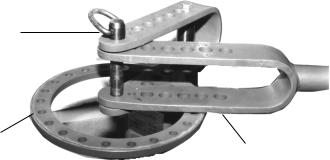
Long Hitch Pin (#1)
|
|
|
|
Inner Handle (#8) |
|
Ring Assembly/Die Receiver (#10) |
|
|
not shown |
||
Outer Handle/Die Receiver (#9) |
|||||
|
|
||||
|
Figure 2-Assemble Handle |
||||
Step 5) |
The Inner Handle (#8) slides into the Outer Handle/ Die Receiver (#9) and is held in place by |
||||
|
a Handle Pin and Hair Clip (#12). The Inner Handle (#8) can be fully extended by pulling out |
||||
|
the Handle Pin and Hair Clip (#12) and pulling out the Inner Handle until the hole in the Outer |
||||
|
Handle (#9) lines up with the holes at the end of the Inner Handle (#8). |
||||
Step 6) |
Place the Outer Handle Die Receiver (#9) between the Die Receiver (#10) and secure it in place |
||||
|
using one of the Long Hitch Pins (#1). |
|
|
|
|
Basic Operation
Following are instructions on the primary uses of your Compact Bender. Additionally, information is included on the many ways to use your Compact Bender, along with specific examples. Becoming familiar with the Compact Bender and its many uses will allow you to make a variety of useful items.
As the operator, you will have to decide on the way in which you will be using your Compact Bender. The following are the basic steps you will need to take when working with the Compact Bender.
Use an appropriate measuring device to measure and:
•Decide on material and measurements to be used.
•Decide on the appropriate Die. Decide on the best placement of the Die for your particular bend.
•Decide on the appropriate attachment, Stop Block or Right Angle Bend. Correct orientation of Stop
Block.
•Insert stock into the Bender and position it properly. Make the first bend.
•Check the angle and direction of the bend.
•Make all consequent bends. Adjust the workpiece as needed.
Warning: Keep fingers and hands away from moving parts at all times.
SKU 38471 |
For technical questions, please call 1-800-444-3353. |
Page 5 |

How the Holes Are Numbered |
|
|
|
|
|
|
|
||
1 2 |
3 |
4 |
5 |
|
Ring Assembly (#10) |
||||
|
|
|
|
||||||
|
|
|
|
|
|
|
|||
Center Point |
|
|
|
|
|
|
|
|
Outer Handle (#9) |
|
|
|
|
|
|
|
|||
|
|
|
|
|
|
|
|
|
|
|
|
|
|
|
|
|
|
|
|
1 2 3 4 5
Figure 3 - Numbering of Holes
Throughout this manual, the holes are often identified by a specific number, i.e., the 3rd hole in the Handle. There are five (5) holes referred to in the Outer Handle/Die Receiver (#9) and 5 holes referred to in the Ring Assembly (#10). For clarification of each hole and its corresponding number, please refer to Figure 3 above.
Use of the Support Pin with the Square Stop Block
Step 1) |
Place the Support Pin (#5) into the hole under the Square Stop Block (#3) so that the Square |
|
Stop Block (#3) will sit correctly in relation to the Ring Assembly/ Die Receiver-see Figure 4. |
|
Long Hitch Pin (#1) |
Square Stop Block (#3)
|
Support Pin (#5) |
|
Figure 4 |
Step 2) |
Insert the Support Pin (#5) in the hole so that it sits under the Stop Block but does not block the |
|
Long Hitch Pin (#1) from going through the hole in the Stop Block and into the lower hole in the |
|
Ring Assembly (#10). |
If the Stop Block is correctly placed you should not have to clamp the workpiece into place. When working with exacting bends, however, it may be helpful to clamp the workpiece into place using vise-grip pliers.
SKU 38471 |
For technical questions, please call 1-800-444-3353. |
Page 6 |
Placement of Die
Dies are placed at one or two different locations depending on the bend to be made:
•A die can be used in conjunction with the Short Hitch Pin (#2) at the intersection of the Outer Handle/Die
Receiver (#9) and the Ring Assembly/Die Receiver (#10).
•The Die can also be placed on the Outer Handle/Die Receiver (#9).
•Two Dies can be placed so that one is on the Outer Handle/Die Receiver (#9) and one at the center point where the Outer Handle/Die Receiver (#9) and Ring Assembly/Die Receiver (#10) intersect-see Figure 3.
Orientation of the Handle
The Handle is always oriented up and on the right side. The Handle is always moved clockwise when a bend is being made.
Use of the Square Stop Block
The Stop Block is so named because it stops the workpiece from turning while the workpiece is being bent, thus “stopping” movement of the workpiece.
When bending your workpiece, place the Square Stop Block (#3) over one of the holes in the Ring Assembly/ Die Receiver (#10). You will have to do some testing to determine placement of the Square Stop Block. You will need to place it over the appropriate hole for the bend you desire and the Die you are using.
Step 1) |
There are four (4) key positions to place the Square Stop Block (#3) in while bending. The four |
|
positions (as seen from looking down on the top of the Square Stop Block) are identified in this |
|
manual by a letter; A, B, C, or D. See Figure 5 on the next page, for the letter and the corre- |
|
sponding position of the Square Stop Block. |
Warning: |
Always position the Stop Block so that it’s hole is oriented to the right side. Even though another |
|
side of the Stop Block may actually face the work piece. If the hole is oriented left instead of |
|
right, this will result in the Stop Block turning which will cause the workpiece to move. |
Step 2) |
Set the appropriate Die into place on the Outer Handle/Die Receiver (#9) between the upper |
|
and lower fork. Secure the Die in place by inserting the Short Hitch Pin (#2) through the Outer |
|
Handle/Die Receiver (#9) and the Square Stop Block. The Square Stop Block (#3) is held in |
|
place against the stock as shown in Figure 7 on page 12. |
Step 3) |
Set your workpiece into position. With the Handle (#9) in the starting position, set the Square |
|
Stop Block (#3) as close to the Long Hitch Pin (#1) at the center position, as possible. |
Note: |
To avoid large spaces between the Stop Block, the Center Pin and selected Die, orient the |
|
Square Stop Block differently, or if possible, move it one hole closer to center. |
SKU 38471 |
For technical questions, please call 1-800-444-3353. |
Page 7 |
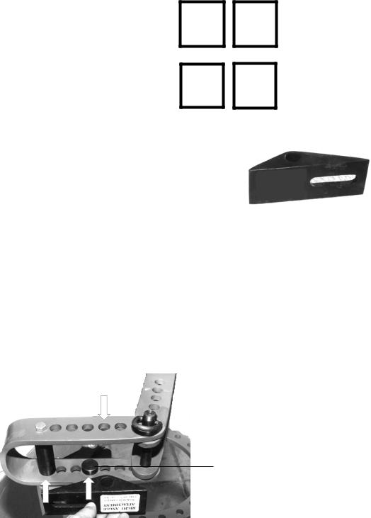
Figure 5 - Stop Block Orientation
C |
D |
Use of the Right Angle Bend Attachment
You will want to use the Right Angle attachment instead of the Stop Block when making a right angle or sharp bend in the stock.
The Right Angle Attachment fits on the Compact Bender only one way.
Step 1) |
Install the Support Pin (#5) under the Right Angle attachment. This will raise it up so that it sits |
|
above the Ring Assembly/Die Receiver-see Figure 6. |
Step 2) |
Set the Support Pin into the 3rd hole on the Ring Assembly/Die Receiver (#10). Line up the hole |
|
in the top of the Right Angle Bending Attachment (#7) with hole #2 in the Ring Assembly Die |
|
Receiver (#10)-see Figure 6. Insert the Long Hitch Pin (#1) through the second hole in the Ring |
|
Assembly/Die Receiver (#10) to secure the Right Angle Bending Attachment (#7) in place. |
Note: |
Your workpiece will not need to be clamped when you are using the Right Angle Bending At- |
|
tachment (#7). |
Step 3) |
Mark the stock at the points that you desire to make a bend. Line up the stock so that the Right |
|
Angle Attachment hits directly at the midpoint of your mark. |
|
Insert Long Hitch Pin (#1) |
Support Pin (#5)
Figure 6-Right Angle Bending Attachment
The Stop and Adjustable Stop Loop
Many times while using the Bender you will need to make repeated bends of the same type and angle. In these instances, using the Adjustable Stop Loop (#26) or the Stop (#4) will save time and allow for precisely the same bends.
Adjust the Stop and Adjustable Stop Loop with a piece of scrap metal prior to using your actual workpiece. This will assure accuracy and aid in obtaining ideal placement of the Stop.
SKU 38471 |
For technical questions, please call 1-800-444-3353. |
Page 8 |
Stop |
|
Step 1) |
Test and decide the amount and distance of Handle rotation to make the desired bend. |
Step 2) |
Place the Stop (#4) into the next hole (clockwise) after your rotation is complete. |
Adjustable Stop Loop
Use the Adjustable Stop Loop (#26) for stops where a finer adjustment is needed. The Adjustable Stop Loop allows for more precise stops as it can be adjusted whereas the Stop (#4) is simply placed into a hole on the Ring.
Step 1) |
Test and decide the amount and distance of Handle rotation to make the desired bend. |
Step 2) |
Place the Adjustable Stop Loop (#26) directly at the point where the rotation of the Handle is to |
|
end. Insert Mounting Bolt (#25) through 3/8” Washer (#24) to hold the Adjustable Stop Loop in |
|
place. Tighten on Washer (#24) and Nut (#27). |
Step 3) |
Try a test bend and adjust the Adjustable Stop Loop (#26) as necessary to obtain a precise |
|
bend. |
Now that the basic operating instructions have been described; it is time to practice using the Compact Bender. We are going to show you how to make several useful items such as handles and anchor bolts. We will also show you how to make letters of the alphabet for use in making decorative signs. Once you practice on the Compact Bender and learn its capabilities, it should be easy to come up with additional uses for the Compact Bender based on your interests and work requirements.
Unpacking
UNPACK AND CHECK CONTENTS
When unpacking your Compact Bender check to make sure the following parts are included. If any parts are missing or broken, please call HARBOR FREIGHT TOOLS at 1-800-444-3353.
Parts List
Part # |
Description |
Quantity |
Part # |
Description |
Quantity |
1 |
Long Hitch Pin |
2 |
15 |
3/8” x 5-1/4” Mounting Bolt |
1 |
2 |
Short Hitch Pin |
1 |
16 |
3/8” x 7/8” Mounting Bolt |
2 |
3 |
Square Stop Block |
1 |
17 |
1” Die |
1 |
4 |
Stop |
1 |
18 |
1-1/4” Die |
1 |
5 |
Support Pin |
1 |
19 |
1-1/2” Die |
2 |
6 |
Ring Assembly Spacer |
1 |
20 |
1-3/4” Die |
1 |
7 |
Right Angle Bending Attachment |
1 |
21 |
2” Die |
1 |
8 |
Inner Handle |
1 |
22 |
2-1/2” Die |
1 |
9 |
Outer Handle/Die Receiver |
1 |
23 |
3” Die |
1 |
10 |
Ring Assembly/Die Receiver |
1 |
24 |
3/8” Washer |
2 |
11 |
Stand |
1 |
25 |
3/8” x 1-3/8” Mounting Bolt |
1 |
12 |
Handle Pin and Hair Clip |
1 |
26 |
Adjustable Stop Loop |
1 |
13 |
Mounting Spacer |
3 |
27 |
3/8” Nut |
1 |
14 |
3/8” Nut |
4 |
|
|
|
Note: Some parts are listed and shown for illustration purposes only and are not available individually as replacement parts.
SKU 38471 |
For technical questions, please call 1-800-444-3353. |
Page 9 |
 Loading...