


Service Document
Exchange Set
YACHT BOY 10 WR5401
Service |
Es gelten die Vorschriften und Sicherheitshinweise |
|
S gemäß dem Service Manual "Sicherheit", Material- |
||
Manual |
nummer 720108000001, sowie zusätzlich die even- |
|
Sicherheit |
tuell abweichenden, landesspezifischen Vorschrif- |
|
ten! |
||
Safety |
||
|
||
|
The regulations and safety instructions shall be |
|
Materialnr./Part No. |
S valid as provided by the "Safety" Service Manual, |
|
720108000001 |
part number 720108000001, as well as the |
|
respective national deviations. |
||
|
Dieses Service Dokument ist nur in Datenform verfügbar This Service Document is only available as data
Änderungen vorbehalten/Subject to alteration
Made by GRUNDIG in Germany • HS-41 0404 http://www.grundig.com

ALIGNMENT INSTRUCTIONS
(1)ALIGNMENT FOR FM FREQUENCY RANGE
a.Required Instruments FM RF signal generator SSVM
b.Alignment Procedure
Mode |
Adjustment |
|
Procedure |
|
|
|
|
(1) |
Set the power switch to the ON position. |
|
|
|
(2) |
Connect a SSVM to the TP5 and TP6. |
|
|
|
(3) |
Connect the FM signal generator to the input terminal of the rod antenna |
|
|
|
|
(TP1, TP2) |
|
L4 |
|
(4) |
Set the signal of the signal generator to the standard FM band, with frequency |
FM |
|
|
deviation to 22.5 kHz modulation. |
|
VC3 |
|
|
||
|
|
(5) |
With the tuning gang fully closed, set the signal generator to 87.35 MHz ±0.15 |
|
|
|
|
||
|
|
|
|
MHz and adjust L4 for a maximum reading on the SSVM. |
|
|
|
|
With the tuning gang fully open, set the signal generator to 108.25 MHz ±0.25 |
|
|
|
(6) |
|
|
|
|
|
MHz and adjust VC3 for a maximum reading on the SSVM. |
|
|
|
(7) |
Repeat Steps 5 and 6 until the best sensitivity is obtained at both frequencies. |
c. Instrument Connection |
|
|||
(2)ALIGNMENT FOR FM SENSITIVITY
a.Required Instruments FM/AM RF Signal Generator SSVM
b.Alignment Procedure
Mode |
Adjustment |
|
Procedure |
|
|
(1) |
Set the power switch to the ON position. |
|
|
(2) |
Connect a SSVM to the speaker. (TP5, TP6) |
|
|
(3) |
Connect the FM signal generator to the input terminal of the rod antenna (TP1, |
|
|
|
TP2) |
|
L3 |
(4) |
Set the signal of the signal generator to the standard FM band, with frequency |
FM |
|
deviation to 22.5kHz modulation. |
|
VC2 |
|
||
|
(5) |
With the tuning gang fully closed, set the signal generator to 90 MHz and |
|
|
|
||
|
|
|
adjust L3 (stretch or squeeze) for a maximum reading on the SSVM. |
|
|
(6) |
With the tuning gang fully open, set the signal generator to 106 MHz and |
|
|
|
adjust VC2 for a maximum reading on the SSVM. |
|
|
(7) |
Repeat steps 5 and 6 until the best sensitivity is obtained at both frequencies. |
c. Instrument Connection |
|
||
YACHT BOY 10
(3)ALIGNMENT FOR AM IF
a.Required Instruments AM RF Signal Generator SSVM
b.Alignment Procedure
Mode |
Adjustment |
|
Procedure |
|
|
(1) |
Set the power switch to the ON position. |
|
|
(2) |
Connect a SSVM to the TP5, TP6. |
AM |
T1 |
(3) |
Connect the AM signal generator to the loop antenna. |
(4)Set the signal generator to 460 kHz, with 30% modulation. Set the tuning gang fully closed, and adjust T1 for a maximum reading on the SSVM.
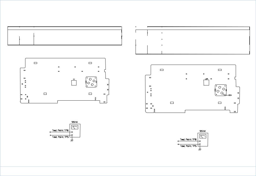
c.Instrument Connection
(4)ALIGNMENT FOR AM FREQUENCY RANGE
a.Required Instruments AM RF Signal Generator SSVM
b.Alignment Procedure
Mode |
Adjustment |
|
Procedure |
|
|
(1) |
Set the power switch to the ON position. |
|
|
(2) |
Connect a SSVM to the TP5, TP6. |
|
|
(3) |
Connect a AM RF signal generator to the loop antenna. |
MW |
L21 |
(4) |
Set the signal generator to 516.5 kHz with 30% modulation. Set the tuning |
VC4 |
|
gang fully closed, and adjust L21 for maximum reading on the SSVM. |
|
|
|
||
|
|
|
|
(5)Set the signal generator to 1631.5 kHz. Set the tuning gang fully open and adjust VC4 for a maximum reading on the SSVM.
(6) |
Repeat Steps 4 and 5 until the best sensitivity is obtained at both frequencies. |
c. Instrument Connection
YACHT BOY 10
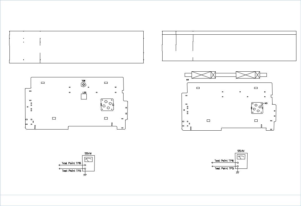
(5)ALIGNMENT FOR AM FREQUENCY RANGE
a.Required Instruments AM RF Signal Generator SSVM
b.Alignment Procedure
Mode |
Adjustment |
|
Procedure |
|
|
(1) |
Set the power switch to the ON position. |
|
|
(2) |
Connect a SSVM to the TP5, TP6. |
|
|
(3) |
Connect a AM RF signal generator to the loop antenna. |
LW |
L22 |
(4) |
Set the signal generator to 138.5 kHz with 30% modulation. Set the tuning |
TC6 |
|
gang fully closed, and adjust L22 for maximum reading on the SSVM. |
|
|
|
||
|
|
|
|
(5)Set the signal generator to 293.5 kHz. Set the tuning gang fully open and adjust TC6 for a maximum reading on the SSVM.
(6) |
Repeat Steps 4 and 5 until the best sensitivity is obtained at both frequencies. |
c. Instrument Connection
(6)ALIGNMENT FOR AM SENSITIVITY
a.Required Instruments AM RF Signal Generator SSVM
b.Alignment Procedure
Mode |
Adjustment |
Procedure |
(1)Set the power switch to ON position.
|
|
(2) |
Connect a SSVM to the TP5, TP6. |
|
|
(3) |
Connect the AM RF signal generator to the loop antenna. |
MW |
L6 |
(4) |
Set the signal generator to 558 kHz, with 30% modulation. Set the tuning gang |
VC1 |
|
fully closed and adjust L6 for a maximum reading on the SSVM. |
|
|
|
||
|
|
(5) |
Set the signal generator to 1440 kHz. Set the tuning gang fully open and adjust |
|
|
|
VC1 for a maximum reading on the SSVM. |
|
|
(6) |
Repeat steps 4 and 5 until the best sensitivity is obtained at both frequencies. |
c. Instrument Connection |
|
||
YACHT BOY 10
 Loading...