


|
|
|
|
|
|
|
|
|
|
|
|
|
|
|
|
|
|
|
|
|
|
|
|
|
|
|
|
|
|
|
|
|
|
|
|
|
|
|
|
|
|
|
|
|
|
|
|
|
|
|
|
|
|
|
|
|
|
|
|
|
|
|
|
|
|
|
|
|
|
|
|
|
|
|
|
|
|
|
|
|
|
|
|
|
|
|
|
|
|
|
|
|
|
|
|
|
|
|
|
|
|
|
|
|
|
|
|
|
|
|
|
|
|
|
|
|
|
|
|
|
|
|
|
|
|
|
|
|
|
|
|
|
|
|
|
|
|
|
|
|
|
|
|
|
|
|
|
|
|
|
|
|
|
|
|
|
|
|
|
|
|
|
|
|
|
|
|
|
|
|
|
|
|
|
|
|
|
|
|
|
|
|
|
|
|
|
|
|
|
|
Radio: |
|
4-5 channel system |
||||
|
|
|
|
|
|
|
|
|
|
|
|
|
|
|
|
||||||
|
|
|
|
|
|
|
|
|
|
|
|
|
|
|
|
|
|
|
w/ 4 std servos (electric), |
||
|
|
SPECIFICATIONS |
Weight: |
|
6 – 6.75 lb |
|
|
|
|
|
|
|
|
or 5 std servos (glow) |
|||||||
|
|
|
|
|
|
|
|
|
|
||||||||||||
|
|
|
|
|
|
|
|
|
|
|
|
|
|
||||||||
|
|
|
|
|
|
Engine: |
|
.46 – .55 cu in |
|||||||||||||
|
|
|
|
[2695-3005 g] |
|
|
|
|
|||||||||||||
|
|
Wingspan: |
|
58 in |
|
|
|
|
|
|
|
|
|
|
[7.5 – 9cc] two-stroke, |
||||||
|
|
|
|
|
|
|
|
|
|
|
|
|
|
|
|
||||||
|
|
|
Wing |
|
22 – 24 oz/sq ft |
|
|
|
|
|
|
|
|
.52 – .70 cu in |
|||||||
|
|
|
|
[1475mm] |
|
|
|
|
|
|
|
|
|
||||||||
|
|
|
|
Loading: |
|
[66 – 74 g/dm2] |
|
|
|
|
|
|
|
|
[8.5 – 11.5cc] four-stroke |
||||||
|
|
|
|
|
|
|
|
|
|
|
|
|
|
|
|||||||
|
|
|
|
|
|
|
|
|
|
|
|
|
|
|
|
|
|
|
|
|
|
|
|
Wing Area: |
|
633 sq in |
Length: |
|
52 in |
|
|
|
|
Motor: |
|
RimFire .55 (42-60-480) |
|||||||
|
|
|
|
[40.9 dm2] |
|
|
[1320mm] |
|
|
|
|
|
|
|
|
w/ APC 13 x 10 E-Prop |
|||||
|
|
|
|
|
|
|
|
|
|
|
|
|
|
||||||||
WARRANTY
Great Planes® Model Manufacturing Co. guarantees this kit to be free from defects in both material and workmanship at the date of purchase. This warranty does not cover any component parts damaged by use or modification. In no case shall Great
Planes’ liability exceed the original cost of the purchased kit.
Further, Great Planes reserves the right to change or modify this warranty without notice.
In that Great Planes has no control over the final assembly or material used for final assembly, no liability shall be assumed nor accepted for any damage resulting from the use by the user of the final user-assembled product. By the act of using the user-assembled product, the user accepts all resulting liability.
If the buyer is not prepared to accept the liability associated with the use of this product, the buyer is advised to return
this kit immediately in new and unused condition to the place of purchase.
To make a warranty claim send the defective part or item to Hobby Services at the address below:
Hobby Services
3002 N. Apollo Dr. Suite 1
Champaign IL 61822 USA
Include a letter stating your name, return shipping address, as much contact information as possible (daytime telephone number, fax number, e-mail address), a detailed description of the problem and a photocopy of the purchase receipt. Upon receipt of the package the problem will be evaluated as quickly as possible.
READ THROUGH THIS MANUAL BEFORE STARTING CONSTRUCTION. IT CONTAINS IMPORTANT INSTRUCTIONS AND WARNINGS CONCERNING THE ASSEMBLY AND USE OF THIS MODEL.
Champaign, Illinois
(217) 398-8970, Ext 5 airsupport@greatplanes.com
Entire Contents © Copyright 2009 |
GPMA1024 Mnl |
|
|
|
|
|
|
|
|
|
|
|
|
|
|
|
|
|
|
|
|
|
|
|
|
|
|
|
|
TABLE OF CONTENTS |
|
|
|
|
|
|
|
|
|
|
|
|
|
|
|
|
|
INTRODUCTION |
|
||||||
|
|
|
|
|
|
|
|
|
|
|
|
|
|
|
|
|
|
|||||||||
INTRODUCTION . . . . . . . . . . . . . . . |
. . |
. |
. |
. |
|
. 2. . |
|
Thank. . . . .you. . for. . purchasing the Great Planes Zlin 526 |
||||||||||||||||||
|
AMA . . . . . . . . . . . . . . . . . . . . . . . . . . 2. |
. Akrobat. . . . .ARF!. . .This. . sport. scale model is patterned after the |
||||||||||||||||||||||||
SAFETY PRECAUTIONS . . . . . . . . . . . |
. |
. |
. |
. |
. |
|
.3 . |
.original. . . . Zlin. . 526 Akrobat which was first seen at airshows |
||||||||||||||||||
LITHIUM BATTERY HANDLING & USAGE . |
. . |
. |
. |
. |
|
. |
3. . |
|
in. .the 1960’s.. The Zlin, along with the famous de Havilland |
|||||||||||||||||
DECISIONS YOU MUST MAKE . . . . . . . . |
. |
. |
. |
. |
. |
. 3. |
. Chipmunk,. . . . . paved the road to the modern CAP, Extra, and |
|||||||||||||||||||
|
Glow Engine Option & Required Parts . . . |
. |
. |
. |
. |
. |
|
.3 . |
.Edge. . aircraft era of today.. Like its full-scale counterpart, the |
|||||||||||||||||
|
Electric Motor Option & Required Parts . . |
. |
. |
. |
. |
. |
. 4. |
. Great. . Planes Zlin 526 is a good aerobatics trainer and is a |
||||||||||||||||||
|
Radio System Recommendations . . . . . |
. |
. |
. |
. |
. |
|
.4 . |
.great. . . 3rd airplane choice for a sport pilot who has mastered |
|||||||||||||||||
ADDITIONAL ITEMS REQUIRED . . . . . . . |
. |
. |
. |
. |
. |
|
.4 . |
.the. .high. . -wing trainer and the low-wing sport plane.. |
||||||||||||||||||
|
Adhesives & Building Supplies . . . . . . . . . . . . .4 . |
. . . . . |
|
|
|
|
|
|
|
|
|
|
|
|
|
|
||||||||||
|
Optional Supplies and Tools . . . . . . . . |
. |
. |
. |
. |
. |
. 4. |
. If. you’re. . . . a beginner who is a fan of scale airplanes, we |
||||||||||||||||||
IMPORTANT BUILDING NOTES . . . . . . . |
. . |
. |
. |
. |
|
. |
5. . |
|
recommend. . . . . |
starting with the Hobbico® NexStar™ 46 ARF |
||||||||||||||||
COMMON ABBREVIATIONS . . . . . . . . . |
. |
. |
. |
. |
. |
|
.5 . |
.trainer. . . (HCAA2025). . |
and then moving on to the Great Planes |
|||||||||||||||||
KIT INSPECTION . . . . . . . . . . . . . . . |
. . |
. |
. |
. |
|
. |
5. . |
|
Cherokee. . . . . . GP/EP. . . ARF (GPMA1033) sport scale low-wing |
|||||||||||||||||
KIT CONTENTS . . . . . . . . . . . . . . . . . . . . . . 6. |
. airplane. . . . . before. . . . you try the Great Planes Zlin 526.. When |
|||||||||||||||||||||||||
ORDERING REPLACEMENT PARTS . . . . . |
. |
. |
. |
. |
. |
|
.6 . |
.you’re. . . ready for another airplane, consider trying a kit.. The |
||||||||||||||||||
PREPARE FOR ASSEMBLY . . . . . . . . . |
. . |
. |
. |
. |
|
. |
7. . |
|
Great. . . . Planes. . |
CAP 232 40 Kit (GPMA0232) is an easy and |
||||||||||||||||
ASSEMBLE THE WINGS . . . . . . . . . . . |
. . |
. |
. |
. |
|
. |
7. . |
|
enjoyable. . . . . . build. |
that will reward you with excellent flight |
||||||||||||||||
|
Aileron Servos & Control Horn Installation . |
. |
. |
. |
. |
. |
|
.7 . |
.characteristics. |
and the ability to perform high-performance |
||||||||||||||||
|
Main Landing Gear Installation . . . . . . |
. . . . . |
11. . |
. aerobatic. . . |
maneuvers.. |
|||||||||||||||||||||
|
Finish the Wings . . . . . . . . . . . . . . . . . . . 12. . |
. . . . . . . . |
|
|
|
|
|
|
|
|
|
|
||||||||||||||
ASSEMBLE THE FUSELAGE . . . . . . . . . |
. |
. |
. |
. |
. 13. . |
.For. . the. . latest technical updates or manual corrections to the |
||||||||||||||||||||
|
Horizontal Stabilizer Installation . . . . . . |
. |
. |
. |
. |
. |
13. . |
. Zlin. . .526 Akrobat visit the Great Planes web site at www.. |
||||||||||||||||||
|
Hinge the Elevator & Rudder . . . . . . . |
. . |
. |
. |
. |
|
.15. . |
|
greatplanes. . . . ..com.. Open the “Airplanes” link, and then select |
|||||||||||||||||
|
Servo, Pushrod & Control Horn Installation |
. |
. |
. |
. |
. 17. . |
. the Zlin 526 Akrobat ARF.. If there is new technical information |
|||||||||||||||||||
GLOW ENGINE INSTALLATION . . . . . . . |
. . |
. |
. |
. |
|
.20. . |
|
or. . changes. . |
|
to this model a “tech notice” box will appear in |
||||||||||||||||
|
Fuel Tank Installation . . . . . . . . . . . |
. . |
. |
. |
. |
|
.21. . |
|
the. . upper. . . . left corner of the page.. |
|||||||||||||||||
|
Mount the Engine . . . . . . . . . . . . . |
. . |
. |
. |
. |
|
.22. . |
. . . . . . . |
|
|
|
|
|
|
|
|
|
|
|
|
||||||
|
Rig the Throttle . . . . . . . . . . . . . . . |
. . |
. . |
. 23. . |
. |
. . . . . . . |
|
|
|
AMA |
||||||||||||||||
ELECTRIC MOTOR INSTALLATION . . . . . . . . . . .25. . |
|
. . . |
|
|
|
|
|
|
|
|||||||||||||||||
|
|
|
|
|
|
|
|
|
|
|
|
|
|
|
|
|
|
|
|
|
|
|||||
|
Mount the Motor & ESC . . . . . . . . . . |
. . |
. . |
. |
25. . |
. . . . . . |
|
of Model Aeronautics If you are not already a |
||||||||||||||||||
|
Mount the Batteries . . . . . . . . . . . . |
. . |
. . |
. |
27. . |
|
Academy |
|||||||||||||||||||
|
. . . . . . . |
|
|
|
|
|
|
|
|
|
|
|
|
|
||||||||||||
FINAL ASSEMBLY . . . . . . . . . . . . . . |
. . |
. . |
. |
28. . |
|
member of the AMA, please join! The AMA is the governing |
||||||||||||||||||||
. . . . . . . . |
|
|
|
|
|
|
|
|
|
|
||||||||||||||||
|
Radio Installation . . . . . . . . . . . . . . . |
. . |
. |
.28. . |
|
body of model aviation and membership provides liability |
||||||||||||||||||||
|
. . . . . . . |
|
|
|
|
|
|
|
|
|
|
|
|
|||||||||||||
|
Cowl Installation . . . . . . . . . . . . . . |
. |
. |
. . |
. |
30. . |
|
insurance coverage, protects modelers’ rights and interests |
||||||||||||||||||
|
. . . . . . . . |
|
|
|
|
|
|
|
|
|
|
|||||||||||||||
|
Propeller & Spinner Installation . . . . . . |
. . . . . 31. . |
|
and is required to fly at most R/C sites.. |
||||||||||||||||||||||
|
. . . . |
|
|
|
|
|
|
|
|
|
|
|
|
|
|
|||||||||||
|
Pilot Installation (Optional) . . . . . . . . . . |
. . |
. |
. 31. . |
. . . . . |
|
|
|
|
|
|
|
|
|
|
|
|
|
|
|||||||
|
Apply the Decals . . . . . . . . . . . . . |
. . |
. . |
. |
.32. . |
|
Academy of Model Aeronautics |
|||||||||||||||||||
|
. . . . . . . |
|
|
|
|
|
|
|
|
|
|
|
|
|||||||||||||
GET THE MODEL READY TO FLY . . . . . . |
. . |
. . |
. |
33. . |
|
5151 East Memorial Drive |
||||||||||||||||||||
. . . . |
|
|
|
|
|
|
|
|
|
|
|
|
|
|
||||||||||||
|
Install & Connect the Motor Battery . . . . |
. . |
. . |
. |
33. . |
|
Muncie, IN 47302-9252 |
|||||||||||||||||||
|
. . . |
|
|
|
|
|
|
|
|
|
|
|
|
|
|
|||||||||||
|
Check the Control Directions . . . . . . . . . |
. . |
. |
.33. . |
|
Tele.. (800) 435-9262 |
||||||||||||||||||||
|
. . . . |
|
|
|
|
|
|
|
|
|
|
|
|
|
|
|||||||||||
|
Set the Control Throws . . . . . . . . . . . |
. |
. |
. |
. |
. 34. . |
|
Fax (765) 741-0057 |
|
|
|
|
|
|
|
|||||||||||
|
. . . . . . |
|
|
|
|
|
|
|
|
|
|
|
|
|
|
|||||||||||
|
|
|
|
|
|
|
|
|
|
|
|
Or via the Internet at: |
||||||||||||||
|
Balance the Model (C..G..) . . . . . . . . . . . |
. . |
. |
.34. . |
. . . . . |
|
|
|
|
|
|
|
|
|
|
|
|
|
|
|||||||
|
Balance the Model Laterally . . . . . . . . |
. . . . . 35. . |
|
http://www.modelaircraft.org |
|
|
|
|
|
|||||||||||||||||
|
. . . . . |
|
|
|
|
|
|
|
|
|
|
|
|
|
|
|||||||||||
PREFLIGHT . . . . . . . . . . . . . . . . . . . |
. . |
. . |
35. . |
. . . . . . . . . . |
|
|
|
|
|
|
|
|||||||||||||||
|
Identify Your Model . . . . . . . . . . . . . |
. |
. |
. |
. |
. 35. . |
|
IMPORTANT!!! |
Two of the most important things you can |
|||||||||||||||||
|
. . . . . . . |
|
|
|
|
|
|
|
|
|
|
|
|
|||||||||||||
|
Charge the Radio Batteries . . . . . . . . |
. . |
. . |
. |
36. . |
|
do to preserve the radio controlled aircraft hobby are to avoid |
|||||||||||||||||||
|
. . . . . |
|
|
full-scale aircraft and avoid flying near or over |
||||||||||||||||||||||
|
Balance Propellers . . . . . . . . . . . . . . |
. . |
. . 36. . |
|
flying near |
|
||||||||||||||||||||
|
. . . . . . . |
|
|
|
|
|
|
|
|
|
|
|
|
|||||||||||||
|
Ground Check & Range Check . . . . . . |
. |
. |
. |
. |
. |
36. . |
|
groups of people.. |
|
|
|
|
|
|
|
||||||||||
|
. . . . |
|
|
|
|
|
|
|
|
|
|
|
|
|
|
|||||||||||
ENGINE & MOTOR SAFETY PRECAUTIONS |
. . . . . 36. . |
. |
|
|
|
|
|
|
|
|
|
|
|
|
|
|
|
|||||||||
AMA SAFETY CODE . . . . . . . . . . . . . . . . . . .37. . |
|
|
|
|
|
|
|
|
|
|
|
|
|
|
|
|
||||||||||
CHECK LIST . . . . . . . . . . . . . . . . . |
. . |
. |
. |
. |
|
.37. . |
|
|
|
|
|
|
|
|
|
|
|
|
|
|
|
|
||||
FLYING . . . . . . . . . . . . . . . . . . . . . |
. |
. |
. |
. |
. 38. . |
. |
|
|
|
|
|
|
|
|
|
|
|
|
|
|
|
|||||
|
Fuel Mixture Adjustments . . . . . . . . . |
. |
. |
. |
. |
. 38. . |
. |
|
|
|
|
|
|
|
|
|
|
|
|
|
|
|
||||
|
Takeoff . . . . . . . . . . . . . . . . . . . |
. |
. |
. |
. |
. 38. . |
. |
|
|
|
|
|
|
|
|
|
|
|
|
|
|
|
||||
|
Flight . . . . . . . . . . . . . . . . . . . |
. . |
. |
. |
. |
|
.39. . |
|
|
|
|
|
|
|
|
|
|
|
|
|
|
|
|
|||
|
Landing . . . . . . . . . . . . . . . . . . |
. |
. |
. |
. |
. |
39. . |
. . . . . . . . . . |
|
|
|
|
|
|
|
|||||||||||
|
|
|
|
|
|
|
|
2 |
|
|
|
|
|
|
|
|
|
|
|
|
|
|
|
|||

PROTECT YOUR MODEL, YOURSELF & OTHERS… FOLLOW THESE IMPORTANT SAFETY PRECAUTIONS
1. Your Zlin 526 Akrobat should not be considered a toy, but rather a sophisticated, working model that functions very much like a full-size airplane.. Because of its performance capabilities, the Zlin 526 Akrobat, if not assembled and operated correctly, could possibly cause injury to yourself or spectators and damage to property..
2. You must assemble the model according to the instructions.. Do not alter or modify the model, as doing so may result in an unsafe or unflyable model.. In a few cases the instructions may differ slightly from the photos.. In those instances the written instructions should be considered as correct..
3. You must take time to build straight, true and strong..
4. You must use an R/C radio system that is in good condition, a correctly sized engine or motor, and other components as specified in this instruction manual.. All components must be correctly installed so that the model operates correctly on the ground and in the air..You must check the operation of the model and all components before every flight..
5. If you are not an experienced pilot or have not flown this type of model before, we recommend that you get the assistance of an experienced pilot in your R/C club for your first flights.. If you’re not a member of a club, your local hobby shop has information about clubs in your area whose membership includes experienced pilots..
6. While this ARF has been flight tested to exceed normal use, if the plane will be used for extremely high stress flying, such as racing, or if an engine larger than one in the recommended range is used, the modeler is responsible for taking steps to reinforce the high stress points and/or substituting hardware more suitable for the increased stress..
7. WARNING: The cowl is made of fiberglass, the fibers of which may cause eye, skin and respiratory tract irritation.. Never blow into or on a part to remove fiberglass dust, as the dust will blow back into your eyes.. Always wear safety goggles, a particle mask and rubber gloves when grinding, drilling and sanding fiberglass parts.. Vacuum the parts and the work area thoroughly after working with fiberglass parts..
We, as the kit manufacturer, provide you with a top quality, thoroughly tested kit and instructions, but ultimately the quality and flyability of your finished model depends on how you build it; therefore, we cannot in any way guarantee the performance of your completed model, and no representations are expressed or implied as to the performance or safety of your completed model..
Remember:Take your time and follow the instructions to end up with a well-built model that is straight and true.
LITHIUM BATTERY
HANDLING & USAGE
WARNING!! Read the entire instruction sheet included with the battery.. Failure to follow all instructions could cause permanent damage to the battery and its surroundings, and cause bodily harm!
• ONLY use a LiPo approved charger..
• NEVER charge in excess of 4..20V per cell..
• ONLY charge through the “charge” lead.. NEVER charge through the “discharge” lead..
• NEVER charge at currents greater than 1C..
• ALWAYS set charger’s output volts to match battery volts..
• ALWAYS charge in a fireproof location..
• NEVER trickle charge..
• NEVER allow battery temperature to exceed 150° F (65° C)..
• NEVER disassemble or modify pack wiring in any way or puncture cells..
• NEVER discharge below 3..0V per cell
• NEVER place on combustible materials or leave unattended during charge or discharge..
• ALWAYS KEEP OUT OF REACH OF CHILDREN..
DECISIONS YOU MUST MAKE
This is a partial list of items required to finish the Zlin 526 Akrobat that may require planning or decision making before starting to build.. Order numbers are provided in parentheses..
Glow Engine Option & Required Parts
If you choose to equip your model with a glow engine, you will need to purchase the items listed below.. Either a twostroke or a four-stroke engine can be used.. The glow engine is mounted inverted..
o3' [900mm] standard silicone fuel tubing (GPMQ4131)
oa suitable propeller per engine manufacturer’s recommendation
oO..S..® Needle Valve Extension kit (optional) (OSMG7290)
3
Two-Stroke Option
oO..S.. 46 AX two-stroke engine (OSMG0547)
oO..S.. Muffler Extension #873 (for 46AX engine using a standard muffler) (OSMG2578)
OR
oJ’Tec JT-601 In-Cowl universal inverted muffler (scale muffler) (JTCG7015)
Four-Stroke Option
o O..S.. FL-70 RC four-stroke engine (OSMG0876)
Electric Motor Option & Required Parts
oElectriFly™ RimFire™ ..55 (42-60-480) Brushless Outrunner motor (GPMG4715)
oElectriFly Medium Motor Mount (GPMG1255)
oElectriFly Silver Series 60A Brushless ESC (GPMM1850)
oAPC 13 x 10 E-Prop (APCQ4140)
o(2) Great Planes ElectriFly 11..1V, 3200mAh 20C LiPo BP Series (GPMP0727)
OR
o(2) Great Planes ElectriFly 11..1V, 3350mAh 25C LiPo Power Series (GPMP0541)
oDeans® Series 2 Male Ultra® adapter (GPMM3143)
o6" [150mm] servo extension (for ESC signal lead) (HCAM2701)
oPolyCharge4™ LiPo battery charger (GPMM3015)
oEquinox™ 1-5 cell LiPo cell balancer (GPMM3160)
o12 Volt DC power supply (HCAP0250) (optional)
oRC Electronics Watt’s Up Watt Meter (RELP0100) (optional)
Radio System Recommendations
o4 channel radio system
o(4) Futaba® S3004 Standard Ball Bearing Servo (FUTM0004)
oFutaba NR4J 4..8V 600mAh Receiver Battery (FUTM1280)
o(2) 12" [300mm] servo extension (HCAM2711 for Futaba)
o6" Y-harness (FUTM4130)
oJ-Series Switch w/ Charge Plug (FUTM4370)
oSwitch & Charge Jack Mounting Set (GPMM1000)
oServo Mounting Screws (Set of 10) (FUTM2550)
ADDITIONAL ITEMS REQUIRED
To finish this airplane you will need the following items..
Adhesives and Building Supplies
o3/8" x 3" Heat Shrink Tubing (GPMM1060)
oR/C foam rubber 1/4" [6mm] thick (HCAQ1000)
oDrill bits: 1/16" [1..6mm], 5/64" [2mm], #48
o1 oz.. [30g] Medium Pro™ CA+ (GPMR6008)
o1 oz.. [30g] Thin Pro CA (GPMR6002)
o1 oz.. [30g] Thin Foam-Safe CA (HOTR1040)
oCA applicator tips (HCAR3780)
oCA debonder (GPMR6039)
oPro 30-minute epoxy (GPMR6047)
oEpoxy brushes (6, GPMR8060)
oMixing sticks (50, GPMR8055)
oMixing cups (GPMR8056)
oThreadlocker™ thread-locking compound (GPMR6060)
oPanel Line Pen (TOPQ2510)
o#64 rubber bands (1/4 lb [113g] box, HCAQ2020)
o18" flexible steel rule (HCAR0460)
oHobbico Retractable Fabric Tape Measure (HCAR0478)
o6-32 tap and drill set (GPMR8102)
oTap handle (GPMR8120)
oPliers with wire cutter (HCAR0625)
oHobbico Heavy Duty Diagonal Cutter 7" (HCAR0627)
oelectric drill
oHobbico ball-end hex wrench set – metric (HCAR0521)
oHobbico ball-end hex wrench set – SAE (HCAR0520)
o(2) 1" [25mm] C-Clamps
oExcel Small Clamp (EXLR5663)
oZona L-Square (ZONR3734)
oMedium T-pins (100, HCAR5150)
oEasy-Touch™ Bar Sander 5..5" (GPMR6169)
oSandpaper assortment
oMasking tape (TOPR8018)
oElectrical tape
oToothpicks, round
oDenatured alcohol (for epoxy clean up)
Optional Supplies and Tools
o21st Century® sealing iron (COVR2700)
o21st Century iron cover (COVR2702)
oRotary tool such as Dremel®
oRotary tool reinforced cut-off wheel (GPMR8200)
oHobbico Z-bend pliers (HCAR2000)
4
oHobby Heat™ micro torch (HCAR0755)
oDead Center™ Engine Mount Hole Locator (GPMR8130)
oAccuThrow™ Deflection Gauge (GPMR2405)
oCG Machine™ (GPMR2400)
oPrecision Magnetic Prop Balancer (TOPQ5700)
oRobart Super Stand II (ROBP1402)
oGreat Planes 1/5th scale Civilian Pilot (red) (GPMQ9062), blue (GPMQ9063), or yellow (GPMQ9064)
IMPORTANT BUILDING NOTES
• There are several types of screws used in this kit:
Self-tapping or sheet metal screws are designated by a number and a length.. For example, #6 x 3/4" [19mm]..
Machine screws are designated by a number, threads per inch, and a length.. For example, 4-40 x 3/4" [19mm]..
Socket Head Cap Screws (SHCS) are designated by a number, threads per inch, and a length.. For example, 4-40 x 3/4" [19mm]
• When you see the term test fit in the instructions, it means that you should first position the part on the assembly without using any glue, then slightly modify or custom fit the part as necessary for the best fit..
• Whenever the term glue is written you should rely upon your experience to decide what type of glue to use.. When a specific type of adhesive works best for that step, the instructions will make a recommendation..
• Whenever just epoxy is specified you may use either 30-minute (or 45-minute) epoxy or 6-minute epoxy.. When 30-minute epoxy is specified it is highly recommended that you use only 30-minute (or 45-minute) epoxy, because you will need the working time and/or the additional strength..
• Photos and sketches are placed before the step they refer to.. Frequently you can study photos in following steps to get another view of the same parts..
• The Zlin 526 Akrobat is factory-covered with Top Flite® MonoKote® film.. Should repairs ever be required, MonoKote can be patched with additional MonoKote purchased separately.. MonoKote is packaged in six-foot rolls, but some hobby shops also sell it by the foot.. If only a small piece of MonoKote is needed for a minor patch, perhaps a fellow modeler would give you some.. MonoKote is applied with a model airplane covering iron, but in an emergency a regular iron could be used.. A roll of MonoKote includes full
instructions for application.. Following are the colors used on this model and order numbers for six foot rolls..
Jet White (TOPQ0204)
Royal Blue (TOPQ0221)
True Red (TOPQ0227)
Charcoal Metallic (TOPQ0407)
• The stabilizer and wing incidences and engine thrust angles have been factory-built into this model.. However, some technically-minded modelers may wish to check these measurements anyway.. To view this information visit the web site at www..greatplanes..com and click on “Technical Data..” Due to manufacturing tolerances which will have little or no effect on the way your model will fly, please expect slight deviations between your model and the published values..
COMMON ABBREVIATIONS
Stab = Horizontal Stabilizer Fin = Vertical Stabilizer LE = Leading Edge
TE = Trailing Edge LG = Landing Gear Ply = Plywood
" = Inches mm = Millimeters
SHCS = Socket Head Cap Screw ESC = Electronic Speed Control LiPo = Lithium Polymer battery 3S = Three cells in series
mAh = Milliamp Hours (refers to the usable capacity of a battery)
To convert inches to millimeters, multiply inches by 25.4 (25.4mm = 1")
KIT INSPECTION
Before starting to build, take an inventory of this kit to make sure it is complete, and inspect the parts to make sure they are of acceptable quality.. If any parts are missing or are not of acceptable quality, or if you need assistance with assembly, contact Product Support.. When reporting defective or missing parts, use the part names exactly as they are written in the Kit Contents list..
Great Planes Product Support
3002 N Apollo Drive, Suite 1
Champaign, IL 61822
Telephone: (217) 398-8970, ext. 5
Fax: (217) 398-7721
E-mail: airsupport@greatplanes.com
5
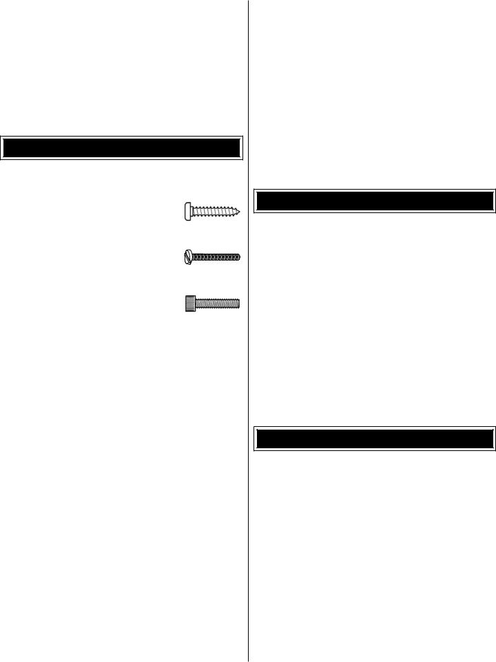
KIT CONTENTS
2
1
3
8
6 |
7 |
4
5
9
10
1 |
- Cowl |
5 |
- Engine Mount & Spinner |
9 |
- Wing Tube |
2 |
- Fuselage & Canopy/Hatch |
6 |
- Fuel Tank |
10 |
- Wing Set |
3 |
- Rudder |
7 |
- Main Landing Gear |
|
|
4 |
- Horizontal Stabilizer w/Elevators |
8 |
- Tail Gear |
|
|
ORDERING REPLACEMENT PARTS
Replacement parts for the Great Planes Zlin 526 Akrobat ARF are available using the order numbers in the Replacement Parts List that follows.. The fastest, most economical service can be provided by your hobby dealer or mail-order company..
To locate a hobby dealer, visit the Hobbico web site at www.. hobbico..com.. Choose “Where to Buy” at the bottom of the menu on the left side of the page.. Follow the instructions provided on the page to locate a U..S.., Canadian or International dealer..
Parts may also be ordered directly from Hobby Services by calling (217) 398-0007, or via facsimile at (217) 398-7721, but full retail prices and shipping and handling charges will apply.. Illinois and Nevada residents will also be charged sales tax.. If ordering via fax, include a Visa or MasterCard number and expiration date for payment..
Mail parts orders and payments by personal check to:
Hobby Services
3002 N Apollo Drive, Suite 1
Champaign IL 61822
Be certain to specify the order number exactly as listed in the Replacement Parts List.. Payment by credit card or personal check only; no C..O..D..
If additional assistance is required for any reason contact Product Support by e-mail at productsupport@greatplanes.. com, or by telephone at (217) 398-8970..
|
REPLACEMENT PARTS LIST |
||
|
|
|
|
Order |
Description |
How to |
|
Number |
purchase |
||
|
|||
|
|
|
|
|
Missing pieces |
Contact |
|
|
|
||
|
Instruction manual |
Product Support |
|
|
|
|
|
|
Full-size plans |
Not available |
|
|
|
|
|
GPMA3379 |
Wing Set Zlin Akrobat |
|
|
GPMA3380 |
Fuselage Zlin Akrobat |
|
|
GPMA3381 |
Tail Set Zlin Akrobat |
Contact your |
|
GPMA3382 |
Landing Gear Zlin Akrobat |
hobby supplier |
|
GPMA3383 |
Cowl Zlin Akrobat |
to purchase |
|
GPMA3384 |
Canopy Hatch Zlin Akrobat |
these items |
|
GPMA3385 |
Decals Zlin Akrobat |
|
|
GPMA3386 |
Wing Tube Zlin Akrobat |
|
|
|
|
|
|
6
PREPARE FOR ASSEMBLY
o 1.. Before you begin assembling your model, use a covering iron set to a medium temperature (about 250° F [121° C]) to tack down any loose or wrinkled covering.. Securely tack down the edges of trim and where seams are present and around the aileron servo hatch covers.. We recommend using a Coverite™ (COVR2700) covering iron with a sock (COVR2702)..
o 2.. Check the pre-hinged ailerons for secure attachment.. If necessary, add several drops of thin foam-safe CA to each side of the hinges.. Clean up any excess glue that runs out of the hinge line using a paper towel.. Allow the glue to fully cure..
ASSEMBLE THE WINGS
Aileron Servos & Control
Horn Installation
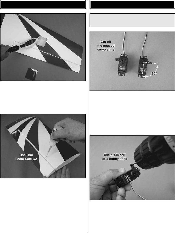
o 1.. Locate the long servo arm that came with your servo.. For Futaba standard servos this is the arm that is already installed on the servo.. For other radio systems, please use the arm that is at least 5/8" [15..9mm] long from the center of the shaft to the outermost hole.. Center two servos using your radio.. Remove the servo arm screw and reposition the servo arm on the splined output shaft so that the arm is 90° (perpendicular) to the servo case side.. Clip off the unused servo arms so that your servos look like those in the photo.. Install the servo arm screw..
o 2.. Use a #48 drill bit to drill the outermost servo arm hole on both aileron servos.. Install the servo mounting grommets.. Note: If you don’t have a numbered drill bit set, you may use a hobby knife to carefully enlarge the servo arm hole.. Work slowly and keep checking the fit using the unthreaded end of one of the 2-56 pushrods.. Minimizing control slop now can prevent poor flying characteristics (or even flutter) later..
7

o o 3.. Cut out three 1/2" x 1" [13mm x 25mm] pieces of thin card stock (not supplied).. You may use construction paper,
an old cereal box, or a manila folder for this purpose.. Lay the servo on a flat surface with the arm hanging down over the edge of your table.. Locate two 12 x 8 x 20mm hardwood blocks.. Position the blocks under the servo mounting tabs and place a piece of card stock in the locations shown.. Holding the blocks and servo in position, use a 1/16" [1..6mm] drill to drill four holes for the servo mounting screws..
o o 4.. Install the four servo mounting screws that came with your servo.. Remove the screws and harden each of the screw holes with thin CA.. This will create a durable screw thread in the wood.. Let the CA cure and reinstall the screws..
o o 5.. With the hardwood blocks attached and each servo arm still centered, position your servo on an aileron servo bay cover so that the servo arm is centered in the opening and exiting the opening.. Please note: If you are using Futaba servos, there are two laser-etched rectangles on each servo bay cover which will help you position your servo..
6.. Repeat steps 3 through 5 for the other aileron servo..
o 7.. Mix up a small batch of 30-minute epoxy and apply it to the hardwood blocks.. Glue each servo block to its servo bay cover.. Use small clamps to hold the hardwood blocks tightly in position.. Position the clamps so that they are clamping the hardwood directly.. The clamps shown here are Excel 3-1/2" [89mm] plastic clamps (EXLR5663)..
o 8.. Attach a 12" [305mm] servo lead extension to each aileron servo.. Use a piece of 3/8" [9..5mm] diameter heat shrink tubing (not supplied) to secure the connection.. Route the servo lead through each wing using the supplied guide string..
o 9.. Route the other end of the servo lead through the hole in the top of each wing..
8
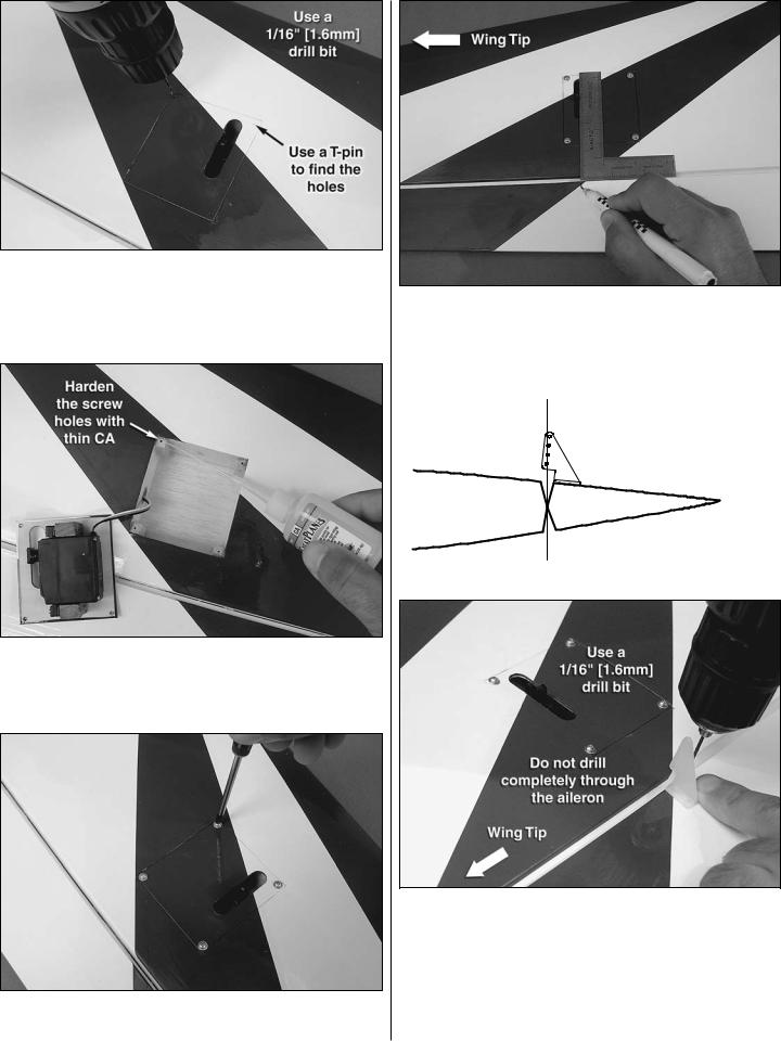
o 10.. Find the pre-drilled holes at each corner of each servo bay cover.. Use a T-pin to poke holes though the covering and fit each servo bay cover to its wing.. Use a 1/16" [1..6mm] drill bit to drill four holes to attach the aileron servo bay covers to the wing..
o 11.. Locate eight #2 x 3/8" [9..5mm] sheet-metal screws and eight #2 flat washers.. Thread these into the holes you drilled.. Remove the screws and the servo bay covers and harden the screw holes with thin CA..
o 12.. Reinstall the aileron servo bay covers using the #2 screws and washers..
o o 13.. Working with one wing now, make a mark using a felt-tip pen directly behind the aileron servo arm.. Use a builder’s triangle or builder’s square to ensure that you mark directly behind the servo arm..
 POSITION THE HORN
SO THAT THE HOLES
ARE DIRECTLY ABOVE
THE HINGE LINE.
o o 14.. Locate one nylon control horn.. Discard the backing plate that is attached to it.. Center the horn along the line you made.. Center the horn fore and aft so that the holes are directly above the hinge line (see sketch above).. Use a 1/16" [1..6mm] drill to drill two 1/2" [13mm] deep holes for the control horn.. Note: Do not drill through the aileron completely.. You may wrap a piece of masking tape around the drill bit 1/2" [13mm] from the tip to act as a drill stop..
9
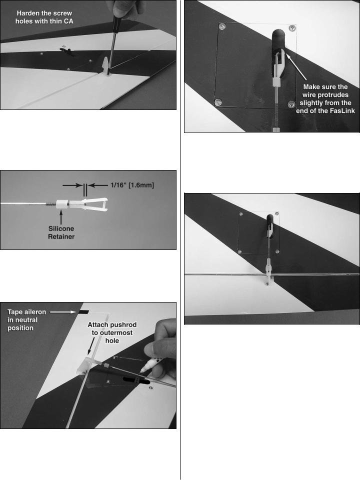
o o 15.. Use two #2 x 1/2" [13mm] sheet-metal screws to attach the control horn to the aileron.. Important: Remove the screws and harden the holes with thin CA.. Reinstall the screws..
o 16.. Repeat steps 13 through 15 for the other wing..
o 17.. Locate the two 2-56 x 12" [305mm] threaded aileron pushrods, two nylon clevises, and two silicone clevis retainers.. Slide a silicone retainer on each pushrod and thread each clevis on so that at least 1/16" [1..6mm] of thread protrudes past the clevis barrel..
o 18.. Center your aileron servos using your radio.. Place a piece of tape across the inboard edge of the ailerons to hold them in the neutral position during this step.. Attach each pushrod to the outermost hole of each aileron control horn.. Extend the pushrod forward and line it up with the servo arm hole.. Mark the pushrod at the hole..
o 19.. Bend the pushrod 90° at the mark that you made.. Connect the pushrod to the outermost hole in the servo arm.. Install a nylon FasLink™ and cut the excess end of the pushrod.. If you use a Dremel tool with a cutoff wheel, remove the nylon FasLink™ before cutting the wire to avoid melting the plastic.. Do this for both wings..
o 20.. With your radio still on, adjust the length of each pushrod until the control surface is neutral (zero control throw).. You may do this by removing the clevis from the control horn and rotating it to adjust the length of the pushrod.. Move the ailerons through their full rate of travel and check for any interference between the linkages and the servo bay covers.. If necessary, trim away the opening in the servo bay cover.. When you’re done, slide the silicone clevis retainer into position..
10
Main Landing Gear Installation
o 1.. Locate the four 4mm wheel collars.. Fit two wheel collars and a wheel onto the axles as shown.. For each axle, mark the position of the wheel collars on the axle.. Use a fine-point felt-tip pen and make the mark on the axle though the set screw hole as shown.. Remove the collars and the wheel..
o 2.. File a 1/8" [3..2mm] wide flat on each axle for each wheel collar’s set screw.. A metal file or a Dremel® tool with a fiber-reinforced cutoff wheel attachment are recommended.. Install the wheels and wheel collars using a drop of threadlocking compound on the set screws.. Apply a few drops of light machine oil to the axles when you’re done..
o 3.. Locate four flat nylon straps.. Place these in the cutouts provided on the wing and use a 3/32" [2..4mm] drill to make two holes for each strap using the strap as a guide..
o 4.. Locate eight #4 x 1/2" [13mm] sheet-metal screws.. Temporarily install the landing gear hold-down straps using these screws.. Remove the screws and the straps and harden the holes with one drop thin CA per hole.. Note: Using more than one drop can melt the foam core of the wing, so be careful..
o 5.. Install a completed landing gear leg into each wing as shown.. Install the landing gear hold-down straps and screws..
11
Finish the Wings
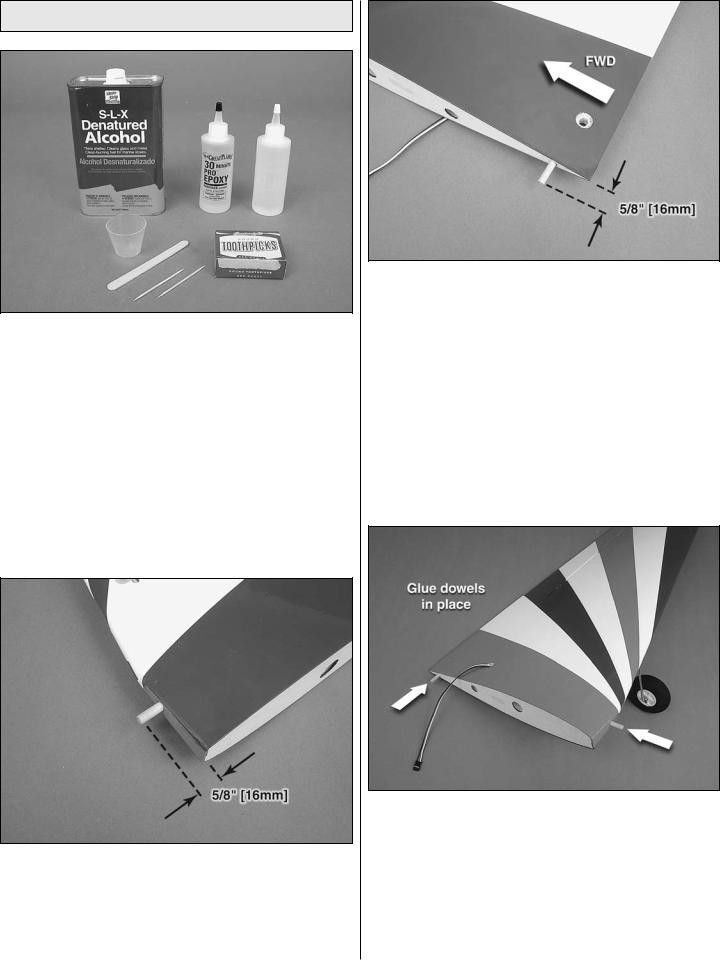
o 1.. For this section you will be working with epoxy.. It is a good idea to have some denatured alcohol and paper towels on hand to help you clean up.. Keep in mind that epoxy must be cleaned up before it cures.. We also recommend that you have your epoxy brushes, mixing sticks (or toothpicks), and mixing cups on hand.. You can mix small amounts of epoxy on a scrap sheet of paper..
o 2.. Locate the two 1-3/16" [30mm] long hardwood dowels.. Test fit these into the holes provided in the leading edge of each wing.. Each dowel should protrude 5/8" [16mm] from the LE of the wing.. If a dowel is too tight, wrap a piece of 150-grit sandpaper around it and rotate the dowel to sand off material.. Sand off a little at a time and recheck the fit..
o 3.. Locate the one 1-3/8" [35mm] long hardwood dowel.. Test fit this in the root wing rib of each wing.. If necessary, sand the dowel until it fits.. The dowel should protrude 5/8" [16mm] from each root rib..
o 4.. Mix up a batch of 30-minute epoxy.. Coat the inside of the two LE dowel holes and the inside of the left wing anti rotation dowel hole.. Coat each dowel with a thin layer of epoxy.. Install the dowels in their proper location.. Make sure that each dowel protrudes 5/8" [16mm].. Wipe up any excess epoxy with some denatured alcohol and a paper towel.. Also, you may want to apply a thin coat of epoxy on the outer portion of each LE dowel.. Coat the dowel and wipe it off with a dry paper towel.. This leaves an ultra thin coat of epoxy and makes the dowel more durable..
12
 Loading...