


Sportster |
20 |
40 |
66 |
|
|
|
|
Engine |
.19-.25 |
.35..45 |
.45-.61 |
Wing Span |
48" |
56" |
61-1/2" |
Wing Area |
400 sq. in. |
550 sq. in. |
675 sq.in. |
Length |
39-1/2" |
43" |
48" |
Weight |
3-1/2-4 lbs. |
5 lbs. |
6-7-1/2 lbs. |
|
|
|
|
MATERIALS NEEDED TO COMPLETE THIS KIT:
4 channel radio |
Wheel collars |
Covering |
Engine |
Wheels |
Instant glue |
Fiberglass cloth/resins |
Epoxy |
White glue |
Engine mounting bolts |
Fuel tank |
|
Propeller |
Spinner |
|
The Super Sportster was designed for the sport flier The Sportster is fast, stable and aerobatic It has good looks, good performance and stability at low speeds For the creative builders it can be detailed to resemble a war bird, Formula 1 racer or a CAP 21 type aerobatic ship Materials are included for both trike gear and conventional gear (taildragger) to help you create your own Sportster
The parts are machine cut and sanded for accurate fit Some parts are razor cut in the 20 size for accuracy Should you notice a difference in size between plans and parts, it is usually because paper plans change size with moisture Most of the parts are self aligning and do not require building over the plans except where specified in the instructions
Different types of glues may be used such as epoxy, Cyanoacrylate or aliphatic (white) resin Be careful when using any kind of glue Make sure you have enough ventilation CA glues (instant) are especially harmful if not used correctly
We suggest that you build on a flat surface to insure a straight wing and fuselage When you build over the plans, cover them with waxed paper so the wood parts are not glued to the plans'
The following tools will be helpful when you build and X-Acto knife, razor plane, saw sanding block, flat building board T Pins hinge slotting kit, drill and drill bits, tap and tap holder, covering iron and heat gun, Dremel tool and cutter tor wire and router bits, soldering iron, screw drivers, needle nose pliers, files, clamps and a good square or right triangle
We recommend a plastic heat shrink covering such as Super Monokote to keep your Sportster light Follow the manufacturer's instructions concerning the use of this covering material
Please read through this step by step instruction book before you start building so you will get an overall idea of the construction steps and avoid mistakes Since these instructions do pertain to the 20, 40 and 60 size Sportsters, refer to the plan and parts list to help you identify the various parts Any differences in the instructions for the various size models will be noted at the appropriate steps with a star (•*)
These instructions and plans were intended tor 2 cycle engine use However starting on page 26 of this booklet, you will find adaptation instructions for the installation of 4-cycle engines
Please inspect all parts carefully before starting to build! If any parts are missing, broken or defective, or it you have any questions about building or flying this airplane, please call us at (217) 398-8970 and we'll be glad to help. It you are calling tor replacement parts, please look up the part numbers and the kit identification number (stamped on the end of the carton) and have them ready.
WARRANTY
Great Planes Model Manufacturing Co., Inc. guarantees this kit to be free of defects in both material and workmanship at the date of purchase This warranty does not cover any component parts damaged by use or modification In no case shall Great Planes' liability exceed the original cost of the purchased kit Further, Great Planes reserves the right to change or modify this warranty without notice.
In that Great Planes has no control over the final assembly or material used for final assembly, no liability shall be assumed nor accepted for any damage resulting from the use by the user of the final user-assembled product.
By the act of using the user-assembled product the user accepts all resulting liability.
If the buyer is not prepared to accept the liability associated with the use of this product, he Is advised to immediately return this kit in new and unused condition to the place of purchase.
READ THROUGH THIS INSTRUCTION BOOK FIRST. IT CONTAINS IMPORTANT INSTRUCTIONS AND WARNINGS CONCERNING THE
ASSEMBLY AND USE OF THIS MODEL.
(SEE WARNING ON BACK COVER)
POBOX788 URBANA, ILLINOIS 61801 (217)398-8970
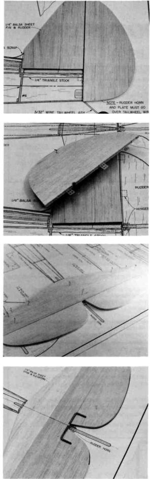
BUILDING THE TAIL SECTION
1. D PREPARE THE FIN AND RUDDER
Prepare the forward and rear fin sections by sanding if necessary for a good fit. Working over the plans, butt glue the fin section together. After the glue is dry, sand both sides of the fin. Also sand both sides of the rudder.
*The 20 size fin is in one piece.
*The 60 size rudder is in two pieces. Glue these together.
Note: Specific instructions for tricycle gear installation are in italics.
2. D CUT THE HINGE SLOTS IN THE FIN AND RUDDER; CUT OUT RUDDER FOR JOINER CLEARANCE
Draw centerlines down the trailing edge of the fin and the leading edge of the rudder. Mark and cut the hinge slots. Two hinges are used above the stabilizer. For conventional gear (Tail dragger) the third hinge should be just below the stab and above the tailwheel strut tab. (For tricycle gear the third hinge should be near the bottom of the rudder. Check the plans.) Relieve (cut out) the leading edge of the rudder for elevator joiner wire clearance. (Shape the rudder leading edge to a "V"now for tricycle gear.) For conventional gear wait to shape the leading edge until the hole is drilled for the tailwheel tiller arm later.
3. D GLUE THE STAB PARTS TOGETHER; SAND THE STAB AND ELEVATORS
Check the fit and butt glue the stabilizer forward and rear sections together. Sand both sides of the stabilizer and elevator halves.
*The 20 size stab is in one piece.
4.D DRILL HOLES IN THE ELEVATOR HALVES FOR ELEVATOR JOINER WIRE
Draw a front to back centerline down the top side of the stab and a centerline down the leading edges of the elevator halves. Mark the center of the elevator joiner wire. Align the stab, elevator and joiner wire and mark the hole locations for the joiner wire arms on the centerline of the elevator leading edge. Drill the holes.
2
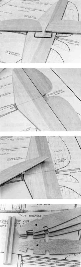
5. D GROOVE OUT THE ELEVATORS FOR JOINER WIRE CLEARANCE
Cut a groove in the elevator leading edge inboard (inside) of the hole so when the joiner wire is installed it will be flush with the leading edge of the elevator. Groove both elevator halves.
6. D TRIAL FIT THE JOINER WIRE
Temporarily install the elevator joiner wire into the elevator halves. Check to make sure that this assembly is aligned properly. Bend the joiner arms if necessary for a perfect fit. DO NOT GLUE THE JOINER WIRE TO THE ELEVATOR HALVES UNTILAFTERTHE PIECESARECOVERED LATER.
7. D CUT HINGE SLOTS FOR THE STAB AND ELEVATOR
Mark and cut the hinge slots for the stab and elevator halves as you did with the fin and rudder. See the plans for locations. Shape the leading edges of the elevator halves to a "V".
BUILDING THE WING PANELS
READ THIS FIRST BEFORE YOU START BUILDING THE
WING PANELS: It is very important that you build a straight wing with no warps or twists or you will get some flying characteristics you didn't expect! Be very careful when you align the ribs, spars, leading edges and trailing edges and sheeting at the various steps below. All these parts should be in their correct positions before you glue them in place. Hold or pin the parts in place, then glue. Use the following instructions to help you build the wing straight and warp free.
Remember: Anyone can build a wing. Only a careful builder can build a straight wing.
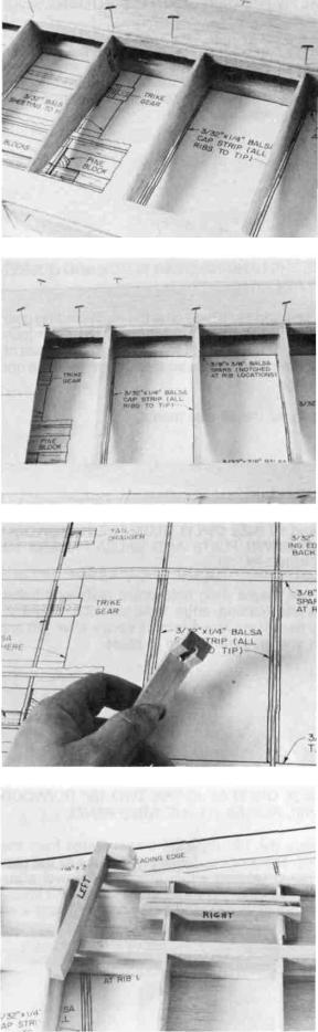
1. D NOTCH THE RIBS FOR LANDING GEAR BLOCK CLEARANCE
Notch the ribs to be installed at locations 2 and 3 for the hardwood main landing gear blocks. Conventional gear block notches are forward on the ribs. (Tricycle gear notches are the rear cutouts.) Check the fit with the block.
Number these ribs 2 and 3. Cut the notches in the ribs for the other wing panel at the same time. (Conventional gear cut outs are shown.)
* 20 size ribs are notched already. Glue the scrap back into the notch you will not use.
3

2. D GLUE THE 1/16" PLYWOOD LANDING GEAR SUPPORTS TO THE RIBS
Start on the right wing panel by gluing the 1/16 ply brace on the left side of rib 2 and on the right side of rib 3. (For the left panel the brace glues on the right side of rib 2 and on the left side of rib 3.) When the glue is dry sand the braces to the rib contour. Note that the landing gear block will be flush with the bottom sheeting not the bottom of the rib. (Conventional gear locations are shown throughout the instructions.)
3. D PIN THE BOTTOM SPAR OVER THE PLANS; PLACE RIBS ON THE SPAR
Pin the bottom spar on the waxed paper covered plans. Temporarily install all the ribs to the spar making sure they are 90 degrees to the building board and that the landing gear notches are down. (Waxed paper is not shown for clarity.)
4. D GLUE THE TRAILING EDGE TO THE RIBS; GLUE THE RIBS TO THE BOTTOM SPAR
For the 40 size, align the top edge of the trailing edge stock to the top edge of the building shim (see size below). For the 20 and 60 size, align the trailing edge to the top of the shim as shown in the drawing below. Use waxed paper in between the shim and the trailing edge and pin them together. Center the trailing edge to the rib ends. Glue the trailing edge to the ribs with the shim pinned to the work surface. Glue the ribs to the bottom spar. DO NOT GLUE THE SHIM TO THE TRAILING EDGE! USE THE SHIM AGAIN WHEN YOU BUILD THE LEFT WING PANEL.
Shim Sizes:
20 = 1/4 x 5/8
40 = 3/32 x 7/8
60 = 1/4 x 3/4
5. D GLUE THE RIBS TO THE LEADING EDGE
Use a straight edge and draw a straight line on the back of the leading edge about 3/32" from the top. Using 1/4 x 1/4 x 36 balsa stock as a shim under the leading edge (for the 40 size), align the top of the ribs to the line and glue them in place to the leading edge. The leading edge is intentionally wider than necessary to allow for slight warpage. Do not fight a slight warp but instead glue the leading edge to the ribs making sure there is at least 3/32" above and below the ribs for sheeting. Later the excess will be carved off.
*Use an 1/8" shim for the 20 size.
*Use a 5/8" shim for the 60 size.
4
6. D ADD THE TOP SPAR, TOP LEADING EDGE SHEET-
ING AND TOP TRAILING EDGE SHEETING
Glue the top spar in place. Glue the top leading edge sheeting between the leading edge and the dotted line on the top spar shown on the plans. Align the top trailing edge sheeting even with the back of the trailing edge and glue it in place.
7. D ADD THE TOP CENTER SECTION SHEETING AND CAP STRIPS
Glue the top center section sheeting in place. Glue the front piece on first. Then cut the rear piece to fit and glue it in place. Add the top cap strips. Note that the cap strip on the tip rib (outer end of the wing) is offset so the outer edge is flush with the outer edge of the rib. After the glue sets up, remove the wing from the building board and check all the glue joints. Add more glue if necessary. Now remount the wing upside down reversing the trailing edge shim on your work surface.
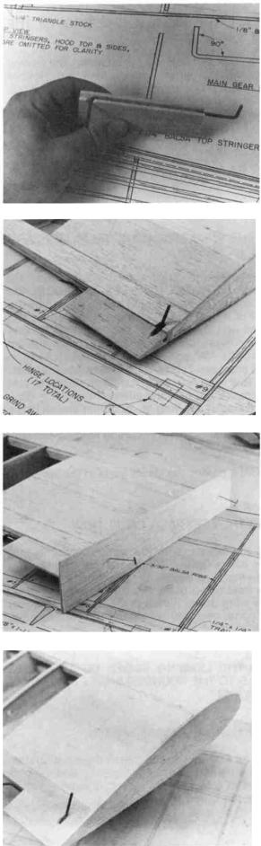
8. D PREPARE THE MAIN LANDING GEAR BLOCK
Glue the torque block to the inboard (inside) end of the ungrooved side of the landing gear block. The grooved side of the torque block should face toward the other end of the long landing gear block. After the glue dries, drill a 5/32" hole down through the landing gear block, using the groove in the torque block as a guide. Epoxy is recommended for the above procedure.
9. D TRIAL FIT THE LANDING GEAR BLOCK ASSEMBLY
Temporarily install the landing gear support assembly into the wing. Custom fit the assembly as follows. Shape the bottom end of the torque block to fit the contour of the wing sheeting to which it mates. The top of the long grooved block should be flush with the bottom sheeting (not yet installed).
5

10. D TRIAL FIT THE MAIN GEAR WIRE INTO THE GEAR BLOCK
Remove the landing gear block from the wing and temporarily install the landing gear wire. The torque arm should slide into the hole you drilled earlier with the long arm resting in the groove in the long block. Custom fit as necessary. Remove the wire.
11. D GLUE THE LANDING GEAR BLOCK AND GUSSET IN PLACE
Use 5 minute expoxy to glue the main landing gear block in place. Add the small gusset under the outer (outboard) end of the long block. Fill the groove at both ends of the long block with scrap balsa so foreign matter does not
get into the wing.
*Go to step 13 for the 20 size model.
12.D (40 and 60 SIZE ONLY) GLUE THE HARDWOOD HOLD DOWN PLATE AND BALSA FILLERS TO
THE WING PANEL
Add the maple wing hold down plate and balsa fillers behind the leading edge between ribs 1 and 2. Custom fit as necessary. Use 5 minute epoxy after you are sure of the fit and glue the pieces in place.
13. D (20 SIZE ONLY) GLUE THE TWO 1/8" PLYWOOD
DOWEL PLATES TO THE WING PANEL
Remove the 1/8" Plywood dowel plates from the razor cut sheet. The smaller dowel plate glues to the rear of the wing panel leading edge. The larger dowel plate glues to the front of the top and bottom spars. Use epoxy and glue both plates in position between ribs 1 and 2 as shown on the plan.
6
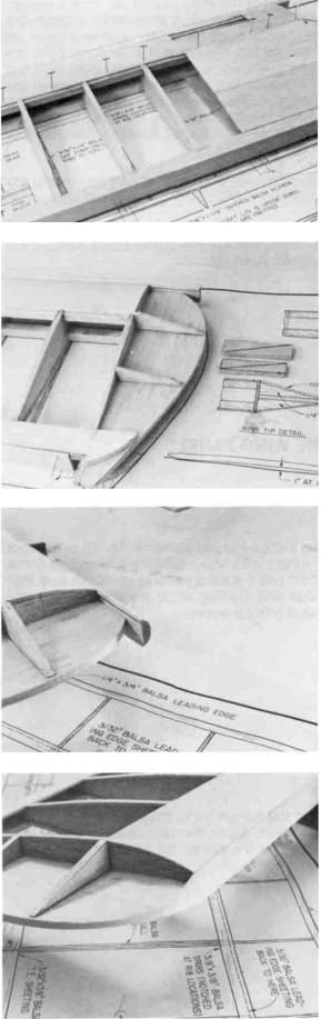
14. D ADD ALL THE BOTTOM SHEETING TO THE WING PANEL
Add the bottom leading edge sheeting, the trailing edge sheeting and the center section sheeting. Relieve (cut away) the leading edge sheeting for landing gear block clearance. (Relieve the center section sheeting for tricycle gear.) Add the bottom cap strips. After the glue dries, remove the wing from your building board and turn it over.
15. D ADD THE WING TIPS, WING TIP FILLERS AND SUPPORT PIECES
Cut off spars and sheeting even with the outboard edge of the tip rib. DO NOT CUT THE LEADING EDGE! Add the wing tip. It should be centered on the tip rib and on the leading edge. For the 40 and 60 size models, prepare and install the upper and lower forward and rear wing tip supports. Using the wing tip detail drawing as a guide, cut two rectangles from the 1/4" scrap piece. Cut the rectangles diagonally and you have two forward and two rear pieces. Custom fit all four supports and glue them in place. Use 1/4" scrap and make and glue the aileron filler piece. Glue it to the inboard side of the wing tip. Add filler pieces to the rear end of the wing tip, top and bottom. Sand these blocks to the aileron contour later after installing hinging and centering the ailerons.
* The 20 size kit includes the above parts in the 1/8" razor cut sheets.
16. D BUILD THE LEFT WING PANEL NOW
Build the left panel in the same manner except build it upside down. Gear cut outs are "up" and landing gear blocks are installed before any sheeting is added. Install the wing hold down plate and fillers in the 40 or 60 models (or the wing dowel plates in the 20 size) after you turn the wing panel over and before the top leading edge sheeting is installed.
17. D SAND THE LEADING EDGES OF THE WING PANELS TO THE ROUNDED SHAPE SHOWN ON THE PLANS
18. D FINISH SAND THE WING PANELS
Sand the leading edge to match the wing tip contour. Remove the trailing edge building shim and cut and sand the wing parts flush with the root rib (inner rib). Finish sand the rest of the wing panel.
7
19. D PREPARE THE CENTER TRAILING EDGE PIECES
With the top of the wing panels up, draw a centerline down the trailing edge of each wing panel. Prepare the grooved center trailing edge pieces by notching them for the servo arm torque rod clearance 3/8" or so in from the wing center. See plans for location. Make right and left pieces. Glue the aileron torque rods into the groove in the
center trailing edge pieces. Use vaseline at the ends of the outer tube so only the tube is glued to the block. Notch the trailing edge of the wing to permit forward movement of the torque rod arms.
* The center trailing edge pieces for the 60 size model are balsa. Cut a groove in the block for torque rod clearance.
20. D GLUE THE CENTER TRAILING EDGE PIECES TO THE WING PANELS
JOINING THE WING PANELS
1. D GLUE THE CENTER RIB TO THE LEFT WING PANEL
Glue the wedge-shaped balsa center rib to the root end of the left wing panel. Make sure the wider edge of the center rib is down and the wing panel is up. Make sure that the leading edge and trailing edge are centered on the tapered rib. Use 5 minute epoxy.
2. D SAND THE CENTER RIB TO THE WING PANEL CONTOUR
Roughcut the center rib to the wing airfoil, leaving it about 1/8" oversize. Sand the remainder away with a sanding block so that the center rib edges are flush with the wing sheeting surfaces.
8
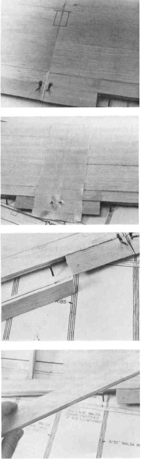
3. D JOIN THE WING PANELS
Join the wing panels upside down. Refer to the dihedral detail on the plans. Align at the leading and trailing edges. Use a straight edge to make sure the wing is straight. Block up the wing 3/4" at the center for the 20 size, 1" for the 40 size and 1-1/4" for the 60 size model. Glue the wing panels together using epoxy, rechecking the alignment before the glue sets up. When the glue is dry, mark the aileron servo well location. The servo well is located directly behind the spar and in the center of the top of the wing.
4. D GLASS THE CENTER SECTION OF THE WING
Use 6 ounce glass cloth (or nylon cloth) and glass the center section glue joint. Use a 4" wide piece of cloth and polyester resin or epoxy. Sand the center section when dry. Apply a second coat of resin or epoxy if necessary.
IMPORTANT — Omitting this step will result in a wing failure during flight and result in a crash.
*Use a 5" wide piece of cloth in the 60 size.
THE AILERONS
1. D PREPARE THE AILERONS
Cut the aileron stock to length and draw a centerline down the leading edge of the ailerons. Mark and drill the torque rod holes. Groove the aileron for torque rod clearance. Make right and left ailerons.
2. D CUT THE HINGE SLOTS; FINAL SAND THE AILERONS
Mark and cut the hinge slots into the ailerons and the wing trailing edge. Shape the leading edge of the ailerons to a "V". Temporarily install the ailerons with hinges to check the fit. Final sand the wing tips to match the aileron contour at neutral. Do not permanently hinge the ailerons until after they are covered.
9
BUILDING THE FUSELAGE
1. D PREPARE THE FUSELAGE SIDES
Mark the inside of the fuselage sides "right" and "left". Relieve the wing saddle area as necessary to match the plans.
STOP! If you plan to install a 4-cycle engine read and follow the instructions on installation of 4-cycle engines at the end of this instruction book starting on page 26.
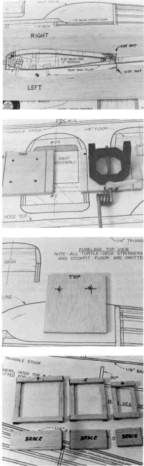
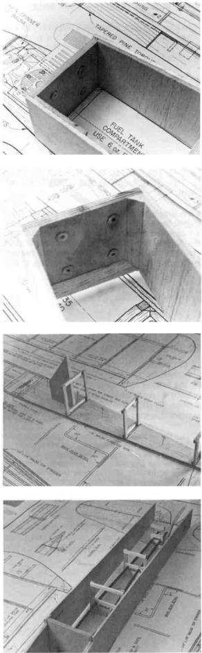
2. D PREPARE BULKHEAD #1
Prepare Bulkhead #1, the firewall. Mark the "top" of the firewall (slanted part is at the bottom) and mark the position of the motor mount. Drill the holes for the motor mount and install the blind nuts. Temporarily install the mount and cut off the bolts that extend into the tank compartment. Drill the hole for the throttle linkage about 1/4" from the top corner of the bulkhead (left or right depending on your engine). (For tricycle gear mark and drill the hole for the steering linkage in the firewall. Also relieve the firewall for steering arm clearance.
3. D PREPARE BULKHEAD #3
Prepare bulkhead #3 by drilling holes for the pushrod outer housings. Use your servos and the plan as a guide to placement.
4. D BUILD THE THREE REAR FORMERS
Make formers #4, 5 and 6 from 1/4" x 1/8" balsa stock. Use the plans as a guide. Also make pushrod braces from 1/8" or 3/32" scrap sheeting. The widths of the braces are the same as that of the formers. They will be installed later when the pushrods housings are added.
STOP! Did you read the 4-cycle engine instructions if you plan to install a 4-cycle? See page 26.
10
5. D GLUE THE DOUBLERS TO THE FUSELAGE SIDES
Using bulkhead #1 as a spacer, install the 1/8" balsa doublers (1/16" for the 20 size) cross-grain on the inside of the fuselage sides. Custom cut pieces from the stock provided. Use slow set epoxy glue or thick Cyanoacrylate. The doubler should extend 5/8" beyond the position of bulkhead #3. Trim and sand the doublers to match the fuselage contour.
6. D MARK BULKHEAD POSITIONS ON THE INSIDE OF THE FUSELAGE SIDES
Mark the positions of Bulkhead #2 and 3 on the fuselage sides. Also mark the position of the balsa dash between #2 and #3 on the fuselage sides.
* Bulkhead #2 in the 20 size is located 1/8" forward of the wing saddle opening to allow for the dowel jig.
7. D DRILL PUSHROD EXIT HOLES
Mark and drill the holes in the fuselage sides for the pushrod exits for the elevator and rudder. See the plans for the locations. A piece of brass tubing sharpened on the inside with an X-acto blade and chucked in an electric drill
makes a neat, clean angled hole for tube-style pushrods.
8. D TRIAL FIT THE WING INTO THE WING SADDLE
Pin the fuselage sides together perfectly aligned. Check the fit to the wing saddle cutout by placing the fuse sides on the wing. Custom sand if necessary but do not change the wing incidence.
11
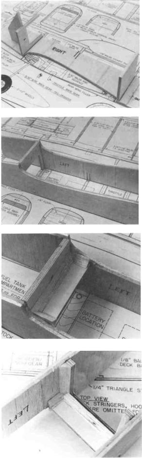
9. D SAND FUSELAGE TAIL; GLUE BULKHEADS #2
AND #3 TO THE RIGHT FUSELAGE SIDE
Slightly relieve the inside edges of the fuse sides at the tail for a better glue joint. Notch a hole for the throttle linkage in the side of bulkhead #2 first before gluing it to the fuselage side. Align and glue bulkheads #2 and #3 to the inside of the right fuse side which you have pinned down to your work surface. Make sure the bulkheads are 90 degrees to the fuselage side and that the tops of the
bulkheads are toward the straight edge of the fuselage sides. Bulkhead #2 has an angled cut on the bottom edge in the 40 and 60 models. (The straight edge of the fuselage side is called the Fuselage Reference Line and will be used later to align the wing and stab to the fuselage.)
* Be careful to locate Bulkhead #2 1/8" forward of the wing saddle opening in the Sportster 20.
10. D GLUE LEFT FUSELAGE SIDE TO BULKHEADS
Align the fuselage side/bulkhead assembly upside down over the top view of the plans. Make sure the flat side is resting flat on the building board and that the bulkheads are aligned to the plans. Pin in place. Glue the other fuse side to bulkheads #2 and #3 making sure the second side is also flat on the building board. Clamp or pin the fuselage in place until the glue is dry.
11. D GLUE IN THE HOLD DOWN PLATES
Add the 1/4" plywood front and rear wing hold down plates and the 1/4" tri stock braces on the bottom of the plates in the servo compartment as shown on the plans. Use epoxy to glue in the plates. You may want to saw or grind away the pushrod clearance area shown on the rear plate now. Otherwise do this in step 23.
* The 20 size model has a rear hold down plate only and uses 1/4" x 1/4" bracing.
12. D GLUE IN THE 1/4" BRACING
Turn the fuselage over and add the 1/4" triangle stock (or 1/4" x 1/4" for the 20) on the front and rear hold down plates. Add the 1/4" tri stock behind bulkhead #2. (40 and 60 only).
12
13. D GLUE IN BULKHEAD #1
Realign the fuselage over the plans and glue the fuse sides to bulkhead #1. Make sure the top of the bulkhead is flat on the building board and that the front of the bulkhead is facing forward.
14. D ADD THE 1/4" BRACING BEHIND THE FIREWALL
Add three pieces of 1/4" triangle stock along the back side of the firewall. Extend the throttle linkage holes (and nosegear steering if used) through the tri stock.
* The 20 size model has 1/4" x 1/4" stock behind bulkhead #1 and in front of bulkhead #2. Glue these pieces in now.
15. D GLUE FORMERS TO THE DECK BASE
Notch the deck base at the corners to clear the doubler as shown on the plans. The deck base should butt up to bulkhead #3. Mark the location of formers #4, 5 and 6 and pin the deck base to the plans. Check the fit of the formers and glue them to the deck base making sure they are 90 degrees to the base.
*The 20 size deck base is razor cut and has precut notches.
16. D PREPARE FORMER BRACES FOR PUSHROD HOUSINGS
Temporarily put the fuselage/bulkhead assembly over the deck base. Use a pushrod housing and mark the locations of the housing holes in the former braces. Make
sure the housing follows as straight a path as possible from bulkhead #3 to the exit. Drill the holes in the braces. Temporarily install the housings to check your work. Remove the housings. Tube in a tube style pushrods are shown here but other types may be used.
13
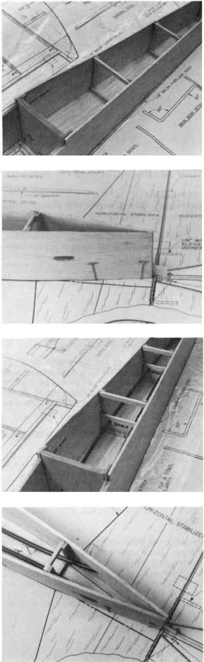
17. D GLUE THE FUSELAGE TO THE DECK BASE
Glue the fuselage sides/bulkhead assembly to the deck base/former assembly. Fuselage sides are glued to the sides of the deck base and the sides of the formers. The deck base should glue to the rear of bulkhead #3.
DO NOT GLUE THE FUSELAGE TOGETHER AT THE TAIL
UNTIL YOU READ THE NEXT STEP!
18. D GLUE THE HINGE TO THE FUSELAGE TAIL; GLUE THE FUSELAGE SIDES TOGETHER AT
THE TAIL
Glue the fuselage sides together at the tail. Conventional gear-glue the rudder hinge just below stab placement. Use the rudder hinge slot as a guide to placement. Do not glue the area at the tail where the tail wheel strut mounting tab will glue later. (Tricycle gear-glue the bottom hinge at the tail at this time. Use the rudder as a guide to placement.)
late glue, glue both elevator and rudder housings in place except at bulkhead #3. This will be glued later when the servos are installed. You may trim the housings at the exits now.
IMPORTANT NOTE: The pushrods supplied in this kit are steel rod-in-a-tub
installing them as straight as possible, as they provide a very rigid linkage between the servos and the control surfaces We do not recommend the use of flexible plastic inner pushrods for this model,astheirelasticitymayresultincontrolsurfaceflutter.Seepage
43 for recommended pushrod hookups.
20. D GLUE IN 1/4" BRACING AT THE TAIL
Glue 1/4" triangle stock (1/4" x 1/4" for the 20 size) at the bottom sides of the deck base between former #6 and the tail. Angle cut the ends of the tri stock at the tail for a good glue joint.
14
 Loading...