


INSTRUCTION MANUAL
Wingspan: 77 in [1950mm]
Wing Area: 1155 sq in [74.5 dm2]
Weight: 13 – 15 lb [5900 – 6800 g]
Wing Loading: 26 – 30 oz/sq ft [79 – 91 g/dm2]
Length: 70 in [1780mm]
Radio: 4+ channel, 6 to 7 servos
Engine / Motor: 1.6 – 1.8 cu in [26 – 30cc] two-stroke,
1.8– 2.1 cu in [30 – 34cc] four-stroke,
1.9– 2.6 cu in [32 – 43cc] gas engine, 63-62-250 RimFire out-runner motor
WARRANTY
Great Planes® Model Manufacturing Co. guarantees this kit to be free from defects in both material and workmanship at the date of purchase. This warranty does not cover any component parts damaged by use or modification. In no case shall Great Planes’ liability exceed the original cost of the purchased kit. Further, Great Planes reserves the right to change or modify this warranty without notice.
In that Great Planes has no control over the fi nal assembly or material used for fi nal assembly, no liability shall be assumed nor accepted for any damage resulting from the use by the user of the fi nal user-assembled product. By the act of using the user-assembled product, the user accepts all resulting liability.
If the buyer is not prepared to accept the liability associated with the use of this product, the buyer is advised to return this kit immediately in new and unused condition to the place of purchase.
To make a warranty claim send the defective part or item to Hobby Services at the address below:
Hobby Services
3002 N. Apollo Dr., Suite 1
Champaign, IL 61822 USA
Include a letter stating your name, return shipping address, as much contact information as possible (daytime telephone number, fax number, e-mail address), a detailed description of the problem and a photocopy of the purchase receipt. Upon receipt of the package the problem will be evaluated as quickly as possible.
READ THROUGH THIS MANUAL BEFORE STARTING CONSTRUCTION. IT CONTAINS IMPORTANT INSTRUCTIONS AND WARNINGS CONCERNING THE ASSEMBLY AND USE OF THIS MODEL.
Entire Contents © Copyright 2007
Champaign, Illinois
(217) 398-8970, Ext 5 airsupport@greatplanes.com
GPMZ1412 for GPMA1412 V1.0

TABLE OF CONTENTS |
|
INTRODUCTION .................................................................... |
2 |
AMA ....................................................................................... |
2 |
IMAA ...................................................................................... |
3 |
SAFETY PRECAUTIONS ...................................................... |
3 |
DECISIONS YOU MUST MAKE............................................. |
3 |
Building Stand................................................................... |
3 |
Radio Equipment .............................................................. |
4 |
Engine Recommendations................................................ |
4 |
Glow Engine Requirements .............................................. |
4 |
Brushless Motor Requirements ........................................ |
5 |
Gas Engine Requirements................................................ |
5 |
Propeller ........................................................................... |
5 |
ADDITIONAL ITEMS REQUIRED ......................................... |
6 |
Adhesives & Building Supplies ......................................... |
6 |
Optional Supplies & Tools ................................................. |
6 |
IMPORTANT BUILDING NOTES........................................... |
6 |
ORDERING REPLACEMENT PARTS ................................... |
7 |
COMMON ABBREVIATIONS ................................................ |
7 |
METRIC CONVERSIONS ...................................................... |
7 |
KIT INSPECTION................................................................... |
8 |
KIT CONTENTS..................................................................... |
8 |
PREPARATIONS.................................................................... |
9 |
ASSEMBLE THE WING ......................................................... |
9 |
Install the Ailerons ............................................................ |
9 |
Install the Aileron Servos & Pushrods ............................. |
10 |
Join the Wing Panels ....................................................... |
11 |
ASSEMBLE THE TAIL SECTION & LANDING GEAR ......... |
13 |
Install the Stab, Elevators & Rudder ................................ |
13 |
Install the Tail Gear Assembly.......................................... |
15 |
Install the Elevator Servos & Pushrods............................ |
16 |
Assemble and Install the Main Gear ................................ |
17 |
GLOW ENGINE INSTALLATION .......................................... |
18 |
Mount the Engine............................................................. |
18 |
Install the Fuel Tank (Glow Engine) ................................. |
19 |
Install the Throttle Servo (Glow Engine) .......................... |
20 |
GAS ENGINE INSTALLATION ............................................. |
22 |
Mount the Engine............................................................. |
22 |
Install the Fuel Tank (Gas Engine)................................... |
23 |
Install the Ignition Equipment (Gas Engine) .................... |
25 |
Install the Throttle Servo (Gas Engine)............................ |
26 |
BRUSHLESS MOTOR INSTALLATION................................ |
28 |
Mount the Motor............................................................... |
28 |
Install the Battery & ESC Trays........................................ |
29 |
INSTALL THE RUDDER SERVOS........................................ |
31 |
Install the Rudder Servos in the Forward Position ........... |
32 |
Install the Rudder Servos in the Aft Position.................... |
34 |
FINISH THE MODEL............................................................. |
35 |
Install the Radio System .................................................. |
35 |
Install the Cowl................................................................. |
37 |
Install the Canopy Hatch.................................................. |
39 |
Install the Belly Pan, Prop & Spinner ............................... |
40 |
Apply the Decals.............................................................. |
41 |
GET THE MODEL READY TO FLY ....................................... |
41 |
Battery Precautions ......................................................... |
41 |
Check the Control Directions ........................................... |
42 |
Set the Control Throws .................................................... |
42 |
Balance the Model (C.G.) ................................................ |
43 |
Balance the Model Laterally............................................. |
43 |
PREFLIGHT .......................................................................... |
44 |
Identify Your Model........................................................... |
44 |
Charge the Batteries........................................................ |
44 |
Balance the Propellers..................................................... |
44 |
Ground Check.................................................................. |
44 |
Range Check ................................................................... |
44 |
ENGINE SAFETY PRECAUTIONS....................................... |
44 |
MOTOR SAFETY PRECAUTIONS ....................................... |
45 |
AMA SAFETY CODE (excerpts).......................................... |
45 |
IMAA SAFETY CODE (excerpts)......................................... |
46 |
CHECK LIST......................................................................... |
47 |
FLYING.................................................................................. |
48 |
Fuel Mixture Adjustments ................................................ |
48 |
Takeoff ............................................................................. |
48 |
Flight ................................................................................ |
48 |
Landing ............................................................................ |
48 |
3D FLYING ............................................................................ |
49 |
ENGINE/MOTOR MOUNTING TEMPLATES........................ |
51 |
INTRODUCTION
For the latest technical updates or manual corrections to the Sukhoi SU-31 1.60 ARF visit the Great Planes web site at www.greatplanes.com. Open the “Airplanes” link, then select the Sukhoi SU-31 1.60 ARF. If there is new technical information or changes to this model a “tech notice” box will appear in the upper left corner of the page.
AMA
We urge you to join the AMA (Academy of Model Aeronautics) and a local R/C club.The AMA is the governing body of model aviation and membership is required to fly at AMA clubs. Though joining the AMA provides many benefits, one of the primary reasons to join is liability protection. Coverage is not limited to flying at contests or on the club field. It even applies to flying at public demonstrations and air shows. Failure to comply with the Safety Code (excerpts printed in the back of the manual) may endanger insurance coverage. Additionally, training programs and instructors are available at AMA club sites to help you get started the right way. There are over 2,500 AMA chartered clubs across the country. Contact the AMA at the address or toll-free phone number below.
Academy of Model Aeronautics
5151 East Memorial Drive
Muncie, IN 47302-9252
Tele. (800) 435-9262
Fax (765) 741-0057 Or via the Internet at:
http://www.modelaircraft.org
IMPORTANT!! Two of the most important things you can do to preserve the radio controlled aircraft hobby are to avoid fl ying near full-scale aircraft and avoid fl ying near or over groups of people.
2

IMAA
The Great Planes Sukhoi SU-31 1.60 ARF is an excellent sport-scale model and is eligible to fl y in IMAA events. The IMAA (International Miniature Aircraft Association) is an organization that promotes non-competitive flying of giantscale models. If you plan to attend an IMAA event, obtain a copy of the IMAA Safety Code by contacting the IMAA at the address or telephone number below, or by logging on to their web site.
IMAA
205 S. Hilldale Road
Salina, KS 67401 (913) 823-5569
www.fly-imaa.org/imaa/sanction.html.
PROTECT YOUR MODEL, YOURSELF & OTHERS....FOLLOW THESE IMPORTANT SAFETY PRECAUTIONS
1. Your Sukhoi SU-31 1.60 ARF should not be considered a toy but rather a sophisticated, working model that functions very much like a full-size airplane. Because of its performance capabilities, the Sukhoi, if not assembled and operated correctly, could possibly cause injury to yourself or spectators and damage to property.
2.You must assemble the model according to the instructions. Do not alter or modify the model, as doing so may result in an unsafe or unflyable model. In a few cases the instructions may differ slightly from the photos. In those instances the written instructions should be considered as correct.
3.You must take time to build straight, true and strong.
4.You must use an R/C radio system that is in first-class condition, and a correctly sized engine and components (fuel tank, wheels, etc.) throughout the building process.
5.You must correctly install all R/C and other components so that the model operates correctly on the ground and in the air.
6.You must check the operation of the model before every fl ight to insure that all equipment is operating and that the model has remained structurally sound. Be sure to check clevises or other connectors often and replace them if they show any signs of wear or fatigue.
7.If you are not an experienced pilot or have not flown this type of model before, we recommend that you get the assistance of an experienced pilot in your R/C club for your fi rst fl ights. If you’re not a member of a club, your local hobby shop has information about clubs in your area whose membership includes experienced pilots.
8.While this kit has been flight tested to exceed normal use, if the plane will be used for extremely high-stress flying, such as racing, or if an engine larger than one in the recommended range is used, the modeler is responsible for taking steps to reinforce the high-stress points and/or substituting hardware more suitable for the increased stress.
9.WARNING: The cowl and wheel pants included in this kit are made of fiberglass, the fibers of which may cause eye, skin and respiratory tract irritation. Never blow into a part (wheel pant, cowl) to remove fi berglass dust, as the dust will blow back into your eyes. Always wear safety goggles, a particle mask and rubber gloves when grinding, drilling and sanding fiberglass parts. Vacuum the parts and the work area thoroughly after working with fi berglass parts.
We, as the kit manufacturer, provide you with a top quality, thoroughly tested kit and instructions, but ultimately the quality and flyability of your fi nished model depends on how you build it; therefore, we cannot in any way guarantee the performance of your completed model, and no representations are expressed or implied as to the performance or safety of your completed model.
Remember:Take your time and follow the instructions to end up with a well-built model that is straight and true.
DECISIONS YOU MUST MAKE
This is a partial list of items required to finish the Sukhoi SU-31 1.60 ARF that may require planning or decision making before starting to build. Order numbers are provided in parentheses.
Building Stand
A building stand or cradle comes in very handy during the build. We use the Robart Super Stand II (ROBP1402) for most of our projects in R&D, and it can be seen in pictures throughout this manual.
3

Radio Equipment
The Sukhoi SU-31 1.60 ARF requires a minimum 4-channel radio system with a standard receiver.
Since the Sukhoi SU-31 1.60 ARF is a large model capable of extreme aerobatics, standard servos should not be used to operate the control surfaces. Servos with a minimum torque rating of 98 oz-in [7.1kg-cm] are required except for the throttle servo which may be operated by a standard servo. The servos shown in this manual that are used for all of the control surfaces are Futaba® S3305 servos. A minimum of six high-torque servos and one standard servo (used for throttle when installing a glow or gas engine) are needed to complete the Sukhoi SU-31 1.60 ARF.
Futaba S3305 Servo High-Torque Standard w/Metal Gears (FUMT0045)
Futaba S3003 Servo Standard (FUTM0031)
Because of heavy loads on the control surfaces, heavy duty servo arms should be used on all of the control surface servos. The throttle servo can use the servo arm supplied with the servo. This manual shows the installation of Great Planes 2" [51mm] aluminum single-sided servo arms. If the rudder servos will be installed in the aft location, six arms will be needed. If the rudder servos are installed in the forward position, only four arms will be needed. See the building instructions for details on the rudder servo positions.
Great Planes Large Scale 2" Single Side Servo Arm (GPMM1110)
The following servo extensions and Y-harnesses were also used to build the Sukhoi SU-31 1.60 ARF as shown in the manual:
(2) 36" [914mm] servo extensions for elevator servos (HCAM2726 for Futaba J-connector)
(2) 36" [914mm] servo extensions for rudder servos when installed in the optional aft location (HCAM2726 for Futaba J-connector)
(2) 24" [610mm] servo extensions for aileron servos (HCAM2721 for Futaba J-connector)
(2) 6" [152mm] servo extensions for rudder servos when installed in the forward location (HCAM2701 for Futaba J-connector)
(1) 6" [152mm] servo extension for receiver battery pack (HCAM2701 for Futaba J-connector)
(1) 12" [305mm] servo extension for brushless ESC if applicable (HCAM2711 for Futaba J-connector)
If using a radio system that does not support mixing of the elevator, rudder, and aileron servos, the following items will be required:
(2) Hobbico® Pro™ HDY-Harnesses for rudder and aileron servos (HCAM2751 for Futaba J-connector)
(1) Reversing Y-Harness for elevator servos (EMOM0027 for Futaba J-connector)
Note: The list of servo extensions and Y-harnesses is based on the equipment we used to setup the Sukhoi SU-31 1.60 ARF as detailed in the manual. The length or quantity may vary depending on the actual equipment being used, radio locations, etc.
A battery pack with a minimum of 1500mAh capacity should also be used. When flying large models such as the Sukhoi SU-31 1.60 ARF, ALWAYS check the battery condition before each flight. If you are installing a gas engine with an electronic ignition module, a separate battery pack (the EI pack does not need to be high capacity) will also be required in addition to the battery pack used to power the receiver and servos.
Hobbico HydriMax™ 4.8V 3600mAh NiMH Flat Rx U (HCAM6333)
A heavy duty receiver switch and charge jack will also be needed:
Futaba Heavy Duty Switch Harness w/Charge Cord (FUTM4385)
Ernst Charge Receptacle Futaba J FM (ERNM3001)
If installing a gas engine, an additional switch (standard size) and charge jack will also be needed:
Futaba SWH13 Switch Harness & Charge Cord Mini J (FUTM4370)
Engine Recommendations
The recommended engine size range for the Sukhoi SU-31 1.60 ARF is 1.6 to 1.8 cu in [26 to 30cc] two-stroke glow engine, 1.8 to 2.1 cu in [30–34cc] four-stroke glow engine, or 1.9 to 2.6 cu in [32 to 43cc] gasoline engine. We recommend either the O.S.® 1.60 FX glow engine (OSMG0661) or the Fuji-Imvac™ BT-43 EI-2 43cc gasoline engine (FJIG0144). The Sukhoi SU-31 1.60 ARF is also designed to accept a Great Planes 63-62-250kV RimFire™ out-runner brushless motor. All of these power systems will allow the Sukhoi SU-31 1.60 ARF to perform the 3D maneuvers it was designed for and installations are covered in this manual.
Glow Engine Requirements
The only required accessory needed to install a glow engine is a Pitts style muffl er. If using the O.S. 1.60 FX glow engine, the order number for a Pitts style muffl er is Bisson O.S. 1.60 FX Pitts Muffl er (BISG4116).
4

Brushless Motor Requirements
If installing the Great Planes 63-62-250kV RimFire outrunner brushless motor (GPMG4795), you will also need to purchase:
Great Planes Brushless Motor Mount Extra Large (GPMG1265)
Great Planes SS100 100A Brushless ESC (GPMM1870)
9- to 12-cells (3 or 4 11.1V packs) 3200mAh LiPo Batteries:
Great Planes LiPo 11.1V 3200mAh 20C Discharge w/Balance (GPMP0623)
Great Planes Series Deans U 2 to 1 Adapter (GPMM3143)
(2) Great Planes Velcro® Hook & Loop material 1" x 6" (GPMQ4480)
LiPo compatible battery charger such as the Great Planes PolyCharge4™ DC only 4 output LiPo charger (GPMM3015)
Great Planes ElectriFly Equinox™ LiPo Cell Balancer (GPMM3160)
Great Planes Charge Lead Banana Plugs/Deans Male Ultra (GPMM3148)
The included spinner adapter nut is designed specifically to fi t into the tapered prop nut used on the O.S. 1.60 FX glow engine. Because of this, an adapter nut must be purchased to work with the RimFire prop adapter.You can use Tru-Turn™ Adapter Kit O.S. 1.08 (TRUQ3065) or Dave Brown X-Long Adapter Nut 3/8-24 (DAVQ6324). Both of these adapter nuts require a 10-32 spinner bolt that will need to be purchased separately. The length of the bolt will depend on the adapter nut being used. We suggest purchasing a 10-32 x 2-3/4" [70mm] spinner bolt and cutting it to the necessary length. Another option is to purchase the nut and prop washer set for the O.S. 1.60 FX engine, O.S. lock nut set 1.60 FX (OSMG6688). Using the O.S. prop nut will allow you to also use the adapter nut included with the kit as well as the included 5mm prop bolt.
Note: The total recommended voltage for the LiPo battery pack configuration is 33.3V to 44.4V. This can be done in combinations of battery packs ranging in voltage. Be sure that the capacity (mAh) of all packs used are the same value (example: do not mix 3200mAh packs with 5000mAh packs). The battery pack combination should be connected together using the recommended series adapter. The actual quantity of adapters needed depends on the number of packs being used. Each adapter will connect two packs together in series. If three 11.1V packs are joined to make 33.3V, two series adapters will be needed (one series adapter will join two 11.1V packs together to make 22.2V, and the second adapter will combine that 22.2V with the remaining 11.1V pack for a total of 33.3V). If four 11.1V packs are combined for a total of 44.4V, then three series adapters will be needed. Other voltage combinations may require more or fewer adapters.
The recommended hook and loop material is used to join the individual battery packs together, securing them onto
the battery tray, and securing the ESC to the ESC tray. One package of Great Planes hook and loop contains 12" [305mm] of material. We suggest purchasing at least two packages.
The recommended PolyCharge4 will charge up to four LiPo packs simultaneously. A set of charge leads is required for each pack that you plan to charge simultaneously.We suggest purchasing a set of charge leads for each battery pack used in the power system. The PolyCharge4 is a DC-only charger, so a suitable DC power source will also be required.
Gas Engine Requirements
The fuel tank included with this kit is suitable for use with glow fuel. However, if using a gas engine, the fuel tank must be converted to work with gasoline. This can be done by purchasing a Sullivan #484 Gasoline/Diesel fuel tank conversion kit (SULQ2684), two packages of Du-Bro #813 1/8" [3.2mm] I.D. fuel line barbs (DUBQ0670) and at least 3' [914mm] of gasoline compatible fuel tubing (such as Tygon). Without the fuel line barbs, some types of gascompatible fuel line may slip off the metal fuel tubes. If the Sullivan conversion kit is not available, the Du-Bro #400 gas conversion stopper (DUBQ0675) and one package of K&S 1/8" [3.2mm] soft brass tubing (K+SR5127) could also be used to make the conversion.
Also, the hardware needed to mount a gas engine to the fi rewall is not included with the kit. The hardware that is detailed in the building instructions of this manual for mounting the Fuji-Imvac BT-43 EI-2 engine includes four 10-32 x 1-1/4" [32mm] SHCS, four #10 flat washers, four #10 lock washers (split washers), and four 10-32 blind nuts. This hardware can be purchased at a hardware store, home center, or your hobby supplier.
Propeller
Choose the propeller that is appropriate for the power system you are using. If installing the Great Planes 63-62-250kV RimFire out-runner motor, the propeller choice will depend on the battery voltage being used. A 9-cell (33.3V) pack will require a 20" x 10" prop (APCQ2200). A 12-cell (44.4V) pack will require a 18" x 8" prop (APCQ3010). If installing an O.S. 1.60 FX glow engine, we recommend using a 18" x 6" W prop (APCQ1806). If installing the Fuji-Imvac BT-43 EI-2 engine, we recommend using a 20" x 8" prop (APCQ2080).
5
ADDITIONAL ITEMS REQUIRED
Adhesives & Building Supplies
This is the list of Adhesives and Building Supplies that are required to fi nish the Sukhoi SU-31 1.60 ARF.
Pro™ 30-minute epoxy (GPMR6047)
1/2 oz. [15g] Thin Pro CA+ (GPMR6001)
1/2 oz. [15g] Medium Pro CA+ (GPMR6007)
Hobbico 60 watt soldering iron (HCAR0776) or
Hobby Heat™ Micro Torch II (HCAR0755)
Silver solder w/flux (STAR2000)
Petroleum jelly (Vaseline®)
3' [900mm] Standard silicone fuel tubing (GPMQ4131) (for glow engine only)
R/C foam rubber (1/4" [6mm] – HCAQ1000)
Drill bits: 1/16" [1.6mm], 3/32" [2.4mm], 7/64" [2.8mm], 9/64" [3.6mm] 7/32" [5.6mm], 3/16" [4.8mm]
Denatured alcohol (for epoxy clean up)
8-32 Tap and drill set (GPMR8103) (for glow engine only)
Tap handle (GPMR8120) (for glow engine only)
#1 Hobby knife (HCAR0105)
#11 Blades (5-pack, HCAR0211)
Masking tape (TOPR8018)
T-pins (HCAR5150)
Great Planes Pro Threadlocker (GPMR6060)
Dead Center™ Engine Mount Hole Locator (GPMR8130)
Panel Line Pen (TOPQ2510)
1" [25mm] Double-sided foam mounting tape (GPMQ4442)
220-grit Sandpaper (GPMR6185)
21st Century® sealing iron (COVR2700)
21st Century iron cover (COVR2702)
Optional Supplies & Tools
Here is a list of optional tools mentioned in the manual and other items that will help you build the Sukhoi SU-31 1.60 ARF.
Fuel fi ller valve for glow fuel (GPMQ4160)
Fuel fi ller valve for gasoline (GPMQ4161)
1/2 oz. [15g] Thick Pro CA- (GPMR6013)
Stick-on segmented lead weights (GPMQ4485)
Epoxy brushes (6, GPMR8060)
Mixing sticks (50, GPMR8055)
Mixing cups (GPMR8056)
Builder’s Triangle Set (HCAR0480)
36" Metal ruler (HCAR0475)
Pliers with wire cutter (HCAR0630)
Hobbico Duster™ can of compressed air (HCAR5500)
Rotary tool such as Dremel®
Rotary tool reinforced cut-off wheel (GPMR8200)
Servo horn drill (HCAR0698)
CG Machine™ (GPMR2400)
#64 Rubber bands (1/4 lb [113g] box, HCAQ2020)
IMPORTANT BUILDING NOTES
•There are two types of screws used in this kit:
•Self-tapping screws are designated by a number and a length. For example #6 x 3/4" [19mm]
This is a number six screw that is 3/4" [19mm] long.
•Machine screws are designated by a number, threads per inch, and a length. For example 4-40 x 3/4" [19mm]
This is a number four screw that is 3/4" [19mm] long with forty threads per inch.
• When you see the term test fit in the instructions, it means that you should first position the part on the assembly without using any glue, then slightly modify or custom fit the part as necessary for the best fit.
•Whenever the term glue is written you should rely upon your experience to decide what type of glue to use. When a specific type of adhesive works best for that step, the instructions will make a recommendation.
•Whenever just epoxy is specifi ed you may use either 30-minute (or 45-minute) epoxy or 6-minute epoxy. When 30-minute epoxy is specified it is highly recommended that you use only 30-minute (or 45-minute) epoxy, because you will need the working time and/or the additional strength.
•Photos and sketches are placed before the step they refer to. Frequently you can study photos in following steps to get another view of the same parts.
•The Sukhoi SU-31 1.60 ARF is factory-covered with high quality heat-shrink fi lm. Should repairs ever be required, this film can be patched with Top Flite® MonoKote® purchased separately. MonoKote is packaged in six-foot rolls, but some hobby shops also sell it by the foot. If only a small piece of MonoKote is needed for a minor patch, perhaps a fellow modeler would give you some. MonoKote is applied with a model airplane covering iron, but in an emergency a regular iron could be used. A roll of MonoKote includes full instructions for application. Following are the colors used on this model and order numbers for six foot rolls.
True Red – TOPQ0227
Metallic Blue – TOPQ0402
Cub Yellow – TOPQ0220
White – TOPQ0204
Metallic Charcoal – TOPQ0407
6

•The stabilizer and wing incidences and engine thrust angles have been factory-built into this model. However, some technically-minded modelers may wish to check these measurements anyway. To view this information visit the web site at www.greatplanes.com and click on “Technical Data.” Due to manufacturing tolerances which will have little or no effect on the way your model will fly, please expect slight deviations between your model and the published values.
ORDERING REPLACEMENT PARTS
Replacement parts for the Great Planes Sukhoi SU-31 1.60 ARF are available using the order numbers in the Replacement Parts List that follows. The fastest, most economical service can be provided by your hobby dealer or mail-order company.
To locate a hobby dealer, visit the Hobbico® web site at www.hobbico.com. Choose “Where to Buy” at the bottom of the menu on the left side of the page. Follow the instructions provided on the page to locate a U.S., Canadian or International dealer.
Parts may also be ordered directly from Hobby Services by calling (217) 398-0007, or via facsimile at (217) 398-7721, but full retail prices and shipping and handling charges will apply. Illinois and Nevada residents will also be charged sales tax. If ordering via fax, include a Visa® or MasterCard® number and expiration date for payment.
Mail parts orders and payments by personal check to:
Hobby Services
3002 N. Apollo Drive, Suite 1
Champaign, IL 61822
Be certain to specify the order number exactly as listed in the Replacement Parts List. Payment is by credit card or personal check only; no C.O.D.
If additional assistance is required for any reason contact Product Support by e-mail at productsupport@greatplanes.com, or by telephone at (217) 398-8970.
Replacement Parts List
GPMA3070 |
Wing Kit |
GPMA3071 |
Fuse Kit |
GPMA3072 |
Tail Set |
GPMA3073 |
Cowl |
GPMA3074 |
Canopy |
GPMA3075 |
Landing Gear |
GPMA3076 |
Wheel Pants |
GPMA3077 |
Decals |
GPMA3078 |
Spinner |
COMMON ABBREVIATIONS
Fuse = Fuselage
Stab = Horizontal Stabilizer Fin = Vertical Fin
LE = Leading Edge
TE = Trailing Edge
LG = Landing Gear Ply = Plywood
" = Inches mm = Millimeters
SHCS = Socket Head Cap Screw ESC = Electronic Speed Control
METRIC CONVERSIONS
1" = 25.4mm (conversion factor)
1/64" |
= .4mm |
3/4" |
= 19.0mm |
1/32" |
= .8mm |
1" |
= 25.4mm |
1/16" |
= 1.6mm |
2" |
= 50.8mm |
3/32" |
= 2.4mm |
3" |
= 76.2mm |
1/8" |
= 3.2mm |
6" |
= 152.4mm |
5/32" |
= 4.0mm |
12" |
= 304.8mm |
3/16" |
= 4.8mm |
18" |
= 457.2mm |
1/4" |
= 6.4mm |
21" |
= 533.4mm |
3/8" |
= 9.5mm |
24" |
= 609.6mm |
1/2" |
= 12.7mm |
30" |
= 762.0mm |
5/8" |
= 15.9mm |
36" |
= 914.4mm |
7
KIT INSPECTION
Before starting to build, take an inventory of this kit to make sure it is complete and inspect the parts to make sure they are of acceptable quality. If any parts are missing or are not of acceptable quality, or if you need assistance with assembly, contact Product Support. When reporting defective or missing parts, use the part names exactly as they are written in the Kit Contents list.
Great Planes Product Support: 3002 N Apollo Drive, Suite 1 Champaign, IL 61822 Telephone: (217) 398-8970, ext. 5 Fax: (217) 398-7721
E-mail: airsupport@greatplanes.com
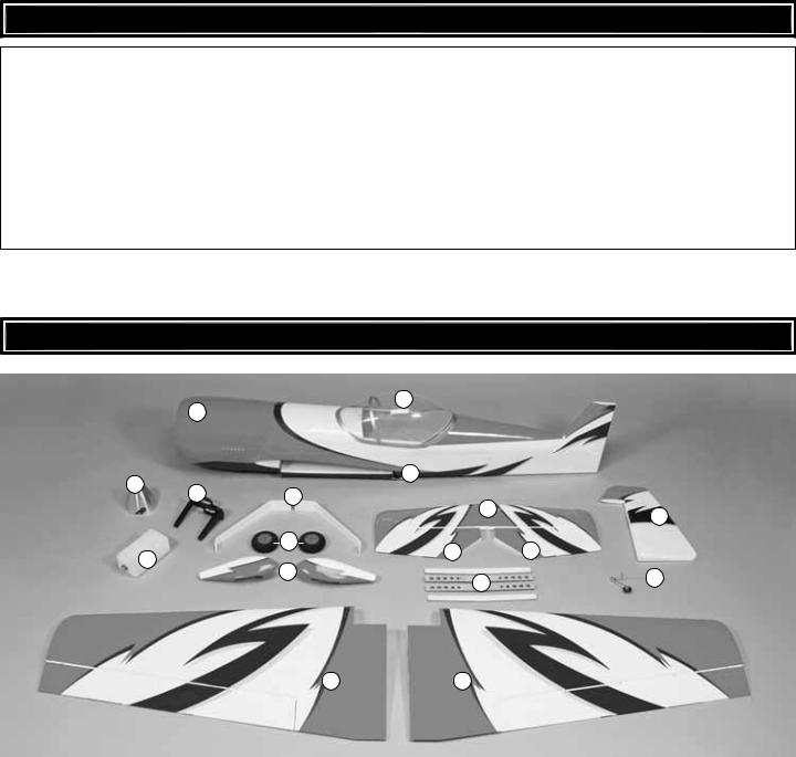
KIT CONTENTS
2
1
3
4
5 |
7 |
10
13
8 |
11 |
11 |
|
6 |
|
9 |
12 |
14 |
|
||
|
|
15 |
16 |
|
|
Kit Contents |
|
|
1 |
Cowl |
|
Wing Joiner (4 pcs.) |
|
|
12 |
|||
2 |
Canopy |
|
13 |
Rudder |
3 |
Fuselage |
|
14 |
Tail Gear Assembly |
4 |
Spinner |
|
15 |
Left Wing w/Aileron |
5 |
Engine Mount |
|
16 |
Right Wing w/Aileron |
6 |
Fuel Tank |
|
|
|
7 |
Main Landing Gear (2) |
|
|
|
8 |
Main Wheels (2) |
|
|
|
9 |
Wheel Pants (L&R) |
|
|
|
10 |
Horizontal Stabilizer |
|
|
|
11 |
Elevators (L&R) |
|
|
|
|
|
|
|
|
|
|
8 |
|
|

PREPARATIONS
1. If you have not done so already, remove the major parts of the kit from the box and inspect for damage. If any parts are damaged or missing, contact Product Support at the address or telephone number listed in the “Kit Inspection” section on page 8.
2. Carefully remove the tape and separate all the control surfaces. Use a covering iron with a covering sock on medium/ high heat to tighten the covering if necessary.Apply pressure over sheeted areas to thoroughly bond the covering to the wood.
ASSEMBLE THE WING
Install the Ailerons
Do the left wing first so your work matches the photos the first time through. You can do one wing at a time, or work on them together.
1. Test fi t the included hinge points into the pre-drilled pockets in the wing panel and aileron. The hinge points should seat into the hinge pockets all the way to the metal pin in order to minimize the gap between the aileron and wing. If necessary, use a hobby knife to enlarge the surface of the hinge pockets until the proper fit is achieved. Test fit the aileron to the wing. The hinge gap between the aileron and wing should only be wide enough to allow a small line of light through. Excessive gap will decrease the effectiveness of the ailerons.
2. Apply a small amount of petroleum jelly or something similar to the center of each hinge to prevent epoxy from sticking to the joints and keeping the hinge from operating smoothly.
Read all of Step 3 before proceeding.
3. Mix up a batch of 30-minute epoxy. Using a toothpick or wood scrap, apply epoxy to the inside of each hinge point pocket. The pockets are drilled through to the open cavity in the wing and aileron, so be careful that you do not apply too much to the walls of the pockets as it will simply drip into the wing. Apply a light coat of epoxy to one end of all the hinges for one wing panel. Insert the hinge points into the pockets in the wing panel, wiping away excess epoxy with denatured alcohol as necessary. Be sure the hinges are inserted in the correct orientation so that the direction of the hinge pin is inline with the TE of the wing. Apply epoxy to the other ends of the hinges and slide the aileron into position over the hinges. Use masking tape to hold the aileron in place while the epoxy cures.
4. Repeat these steps for the right wing panel.
9
Install the Ailerons Servos & Pushrods
1. Installing the servos in the wing will require the use of one 24" [610mm] servo extension for each aileron servo. One Y-harness connector is required and is used to allow the aileron servos to plug into one slot in your receiver. You may have a computer radio that allows you to plug the servos into separate slots and then mix them together through the radio transmitter. If you choose to mix them together with the radio rather than a Y-harness, refer to the manual included with your particular model radio system.
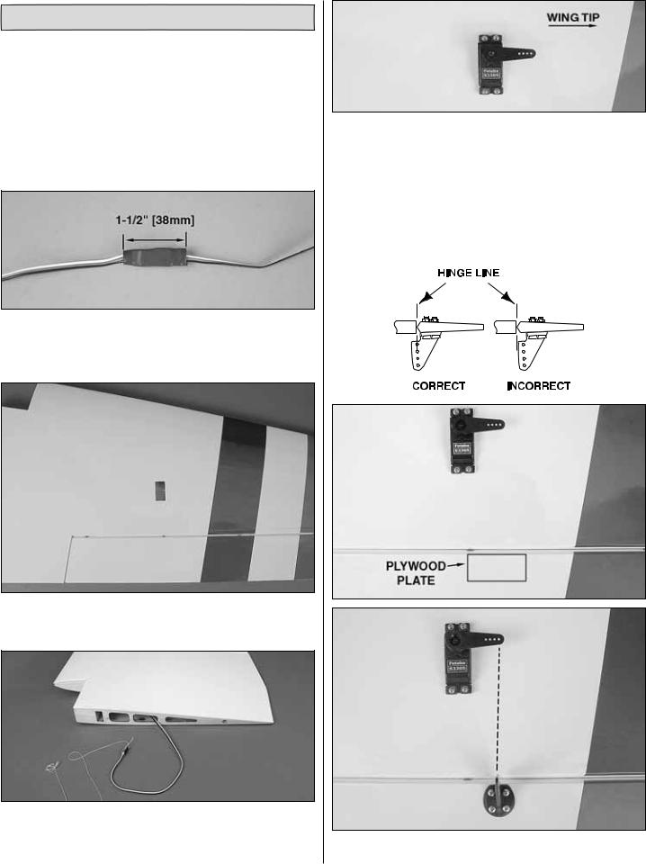
2. Attach the 24" [610mm] servo extension to the aileron servo and secure it with a piece of the included large heat-shrink tubing. Only 1-1/2" [38mm] of heat-shrink tubing is required for each connector.
3. Cut the covering 1/8" [3mm] inside the opening in the underside of the wing for the aileron servo. Use a trim iron to seal the covering to the inner edges of the opening.
4. Tie the string from inside the opening for the aileron servo to the end of the servo extension. Remove the tape holding the other end of the string to the wing root rib and pull the servo wire and extension through the wing.
5.Temporarily position the aileron servo into the servo bay. Drill a 1/16" [1.6mm] hole through the four mounting holes of the servo, drilling through the plywood mounting plate in the wing. Install and remove a servo mounting screw into each of the four holes. Apply a drop of thin CA into the holes to harden the wood. After the glue has cured, install the servo into the opening using the hardware that came with your servo. Center the servo with your radio system and install a servo arm as shown.
The next three images are used for steps 6 and 7
6.The aileron has a plywood plate for mounting the control horn. You can see the outline of it underneath the covering by
10
looking at the aileron at a shallow angle. If you cannot see it, the |
|
|
|
|
|
4. Put a couple of drops of oil onto a rag and wipe the joint. |
|
||
plate is approximately 1-5/8" [41mm] wide and will be inline with |
|
|
||
the servo arm. Use a T-pin to lightly puncture the covering to be |
|
This will prevent rust from forming on the joint. |
|
|
sure you are over the plywood plate. |
|
|
|
|
7. Place a heavy duty nylon control horn on the aileron, |
|
|
|
|
|
|
|
||
positioning it as shown in the sketch inline with the outer hole |
|
|
|
|
of the servo arm. Mark the location for the screw holes. Drill |
|
|
|
|
through the marks you made with a 3/32" [2.4mm] drill bit. (Be |
|
|
|
|
sure you are drilling into the plywood plate mounted in the |
|
|
|
|
bottom of the aileron. Drill through the plate only. Do not drill |
|
|
|
|
all the way through the aileron!). Using a #4 x 5/8" [16mm] |
|
|
|
|
sheet metal screw, install and then remove a screw into each |
|
|
|
|
of the holes. Harden the holes with thin CA. Install the control |
|
|
|
|
horn with four #4 x 5/8" [16mm] sheet metal screws. |
|
|
|
|
8. Locate a .095" x 6" [2.4mm x 152mm] pushrod wire |
|
|
|
|
threaded on one end. Screw a 4-40 nut, a silicone clevis |
|
|
|
|
retainer and a threaded metal clevis onto the threaded end |
|
|
|
|
of the wire 20 turns. Tighten the nut against the clevis using |
|
|
|
|
threadlocking compound and then install the clevis on the |
10. Install the pushrod and clevises to the outer hole in |
|||
outer hole of the aileron control horn. |
the servo arm and the outer hole in the control horn.Adjust the |
|||
9. Be sure the aileron servo is centered and the servo |
linkage until the aileron and the servo arm are both centered. |
|||
Then, tighten the nut against the clevis with threadlocking |
||||
arm is parallel to the hinge line. Install a 4-40 metal solder |
compound. Slide the two silicone clevis retainers to the end |
|||
clevis onto the outer hole in the servo arm. Center the |
of each clevis. |
|||
servo arm parallel with the aileron hinge line and center the |
11. Repeat these steps for the right wing panel. |
|||
aileron. Using the solder clevis as a guide, mark where to cut |
||||
|
|
|
||
the pushrod wire. Remove the pushrod and clevis from the |
|
|
|
|
control horn and the solder clevis from the servo arm. Install |
|
Join the Wing Panels |
||
another silicone clevis retainer onto the wire and solder the |
|
|
|
|
clevis to the pushrod using the “Expert Tip” that follows. |
|
|
|
|
|
|
|
|
|
|
|
|
|
|
|
|
HOW TO SOLDER THE CLEVIS |
|
|
|
TO THE PUSHROD |
|
|
|
1. Where the pushrod will make contact with the solder |
|
|
|
clevis, roughen the wire with 220-grit sandpaper. |
|
|
|
2. Use denatured alcohol to remove any oil residue from |
1. Trim the covering from the servo lead cutouts in the |
||
top of the wing panels. Feed the aileron servo leads through |
|||
the pushrod wire. |
the cutouts. Taping the leads to the top of the wing will keep |
||
Note: Soldering should be done with silver solder, not |
them out of the way when joining the wing panels. |
||
|
|
||
|
|
||
an electrical solder. |
|
|
|
3.Apply a couple of drops of flux to the wire. Slide the solder clevis onto the wire. Using a small torch or soldering iron heat the wire, allowing the heated wire to heat the solder clevis. Apply a small amount of solder to the joint. When the wire and the clevis are hot enough the solder will flow into the joint. Avoid using too much solder, causing solder to flow out of the joint and clump. Use just enough solder to make a good joint. Allow the
wire and clevis to cool. |
2. Glue the 5/16" x 1-1/8" [8mm x 28mm] anti-rotation |
|
pin halfway into one of the wing panels as shown. |
11
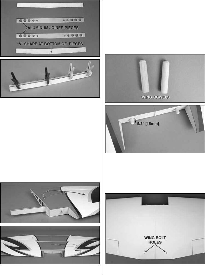
3. Locate the two aluminum wing joiner pieces and the two plywood wing joiner pieces. Use 220-grit sandpaper to thoroughly roughen both sides of each aluminum wing joiner piece and remove the sanding dust from the pieces. Glue the four pieces together using 30-minute epoxy with the two aluminum pieces being on the inside of the stack. Note that the joiner has a slight “V” shape that will give the wing a small amount of dihedral when assembled.The point of the “V” shape is the bottom of the joiner. Wipe away any excess epoxy with a cloth dampened with denatured alcohol and use clamps to hold the pieces together while the epoxy cures. Be sure that the joiner pieces are glued so the edges are flush with each other. Mark a centerline on the assembled wing joiner.
Read all of step 4 and dry fit the parts together to ensure a proper fit before gluing. Sand the wing joiner or root ribs if necessary to achieve the correct fit. The root ribs should join together tightly with no gaps.
4. Use a mixing stick or something similar to coat the inside of the wing joiner pockets of both wing panels with
30-minute epoxy. Thoroughly coat one half of the wing joiner with 30-minute epoxy and insert it into the joiner pocket of one wing panel with the bottom of the “V” shape pointing to the underside of the wing. Coat the root ribs of both wing panels, the protruding end of the wing joiner, and the protruding end of the anti-rotation pin with epoxy. Slide the wing panels together and use tape to hold them tight while the epoxy cures. Wipe away any excess epoxy with denatured alcohol.
5. Bevel the ends of the 3/8" x 1-3/4" [10mm x 45mm] wing dowels. Use epoxy to glue the wing dowels in place. Position the dowels so that 5/8" [16mm] protrudes beyond the front of the wing.
6. Trim the covering from the wing bolt holes in the wing assembly.
12

7. Draw a centerline onto the plywood wing bolt plate as shown. Position the wing bolt plate over the wing bolt holes on the underside of the wing and use a felt-tip pen to trace around it. (Be sure that you center the wing bolt plate over the holes or it may interfere with the installation of the belly pan.)
8. Use a sharp #11 hobby knife or use the following “Expert Tip” to cut the covering 1/16" [1.6mm] inside of the lines you marked. Use care to cut only in the covering and not into the wood. Use alcohol to wipe away the lines. Glue the wing bolt plate in position. Continue the wing bolt holes through the plate using a 1/4" [6mm] drill bit. Clamp a piece of scrap wood against the wing bolt plate to prevent tear out when drilling the holes.
HOW TO CUT COVERING FROM BALSA
Use a soldering iron to cut the covering from the area beneath the wing bolt plate. The tip of the soldering iron doesn’t have to be sharp, but a fi ne-tip does work best. Allow the iron to heat fully.
Use a straightedge to guide the soldering iron at a rate that will just melt the covering and not burn into the wood. The hotter the soldering iron, the faster it must travel to melt a fi ne cut. Peel off the covering.
ASSEMBLE THE TAIL SECTION
& LANDING GEAR
Install the Stab, Elevators & Rudder
1. Just as you did with the ailerons, prepare the hinge point pockets in the stab and elevators by test fi tting the hinges and enlarging the holes as necessary.
2. Locate the stab slots near the aft end of the fuse and trim away the covering.
13

3. Temporarily install the wing onto the fuse using two 1/4-20 nylon wing bolts.The wing dowels will fit into receiving holes in the former behind the LE of the wing.
4. Test fit the stab in the fuse. Center the stab left and right in the fuse. Stand back 15 to 20ft [5m to 6m] and check to be sure the stab is parallel to the wing. If necessary, adjust the stab saddle as needed until the stab and wing are parallel.
5. Measure the distance from the tip of each wing to the tip of the stab. Adjust the stab until the distance from the tip of the stab to the tip of the wing is equal on both sides.
6. Use a felt-tip marker to mark the outline of the fuse onto the top and bottom of the stab.
7. Remove the stab from the fuse and cut the covering just inside the lines you drew. If using a hobby knife to remove the covering, use care to cut only in the covering and not into the wood.
8. Use 30-minute epoxy to glue the stab into the fuse by coating the top and bottom of the stab in the area where you removed the covering. Slide the stab into position. Confi rm that the stab is centered as was done in steps 4 and 5. Wipe away any excess epoxy with a paper towel and denatured alcohol. Do not disturb the model until the epoxy has fully hardened. With the stab secure, you can now remove the wing from the plane.
9. As you did with the ailerons, use a toothpick or wood scrap to apply epoxy to the inside of each elevator and stab hinge point pocket. Apply a light coat of epoxy to one end of all the hinges for the elevators along with a small amount of petroleum jelly at the center of each hinge. Insert the hinge points into the pockets, wiping away excess epoxy with denatured alcohol as necessary. Be sure the hinges are inserted in the correct orientation. Apply epoxy to the other ends of the hinges and slide the elevators into place. Use masking tape to hold the elevators in position while the epoxy cures.
14

10. Attach the rudder in the same manner.
Install the Tail Gear Assembly
1. Trim the covering from the fuse for the tail gear bushing.
2. Apply CA or epoxy to the outside of the bushing and insert the bushing into the hole by gently tapping it into place until fully seated. Be sure not to get glue into the hole in the bushing.
3. Measure 1-1/2" [38mm] back from the LE bevel of the rudder and make a mark on the underside center of the rudder.
4. Use a 5/32" [4mm] drill bit to make a 1/2" [13mm] deep hole at the mark. To improve accuracy, drill a smaller pilot hole at your mark fi rst.
5. Slide the tail gear collar and nylon retainer onto the tail gear assembly as shown. If necessary, use a 1/16" [1.6mm] drill bit to enlarge the hole in the retainer for the tail gear guide wire.
6. Temporarily insert the tail gear assembly into the tail gear bushing and the nylon retainer into the hole you drilled in the rudder. Center the tail gear bracket onto the fuse over the tail gear collar and mark the location of the mounting holes.
15

7. Drill 1/16" [1.6mm] holes at the marks you made.Thread a 2mm x 8mm self-tapping screw into each hole and back it out. Apply a couple drops of thin CA glue to each hole and allow it to harden.
8. Apply CA or epoxy to the nylon retainer and reinstall the tail gear assembly into the bushing and rudder. Do not glue the nylon retainer to the guide wire. The wire must slide freely through the hole in the retainer. Gently tap the retainer in place until approximately 3/16" [4.8mm] protrudes below the bottom of the rudder. Attach the tail gear bracket using two 2mm x 8mm self-tapping screws. Thread the 3mm set screw into the tail gear collar with a drop of threadlocking compound. Cut off the excess guide wire 1/2" [13mm] behind the nylon retainer.
9. Confirm that the tail wheel rotates freely. Oil the axle and adjust the position of the 3mm wheel collar if necessary.
Install the Elevator Servos & Pushrods
1. Trim the covering from the elevator servo bays leaving 1/8" [3mm] around the opening. Use a trim iron to seal down the covering around the edges of the servo bays.
2. Attach a 36" [914mm] servo extension to each elevator servo. Secure the servo extensions with the included heat-
shrink tubing. Feed the servo extensions through the fuse and install the servos into the servo bays with the splines facing forward using the mounting hardware included with the servos. Be sure to harden the servo mounting screws with thin CA.
3. Attach a servo arm to each elevator servo pointing downward.
4. Just as you did with the ailerons, begin assembly of the elevator pushrods using two .095" x 12" [2.4mm x 305mm] pushrod wires threaded on one end, two 4-40 clevises and two 4-40 nuts. Attach the clevis of each pushrod to the servo arms and use the pushrod as a guide to position the control horns onto the underside of the elevators. Secure the control horns to the elevators with #4 x 5/8" [16mm] sheet metal screws, being sure that you are drilling the screw holes through the plywood plates in the elevators. Do not drill all the way through the elevators! Center the elevators and use a solder clevis to mark where to cut the pushrod wires. Cut the wires, solder the clevises to the pushrods and attach the pushrods to the elevators, securing the clevises with silicone clevis retainers.
Note: The Sukhoi SU-31 1.60 ARF is setup for either forward (pull-pull system) or aft (pushrod system) rudder servo positions in order to offset ballast that may be required to balance the airplane. The rudder servos will be installed after the power system is put in place. After the installation of the power system, the current C.G. of the plane can be checked which will determine the optimum location of the rudder servos.
16
 Loading...