


Instruction Book
Welcome to the World of Radio Control Model Airplanes!
READ THROUGH THIS INSTRUCTION
BOOKLET FIRST. IT CONTAINS IMPORTANT
INSTRUCTIONS AND WARNINGS CONCERN-
ING THE BUILDING AND USE OF THIS
MODEL.
WARNING!
This R/C kit and the model you will build is not a toy! It is capable of serious bodily harm and property damage. IT IS YOUR RESPONSIBILITY AND YOURS ALONE — to build this kit correctly, properly install all R/C components and flying gear (engine, tank, pushrods, etc.) and to test the model and fly it only with experienced, competent help in accordance with all safety standards and common sense as set down in the Academy of Model Aeronautics Safety Code. It is suggested that you join the AMA and become properly insured before you attempt to fly this model. IF YOU ARE JUST STARTING R/C MODELING, CONSULT YOUR LOCAL HOBBY SHOP OR WRITE TO THE ACADEMY OF MODEL AERONAUTICS TO FIND AN EXPERIENCED INSTRUCTOR IN YOUR AREA.
Academy of Model Aeronautics 5151 East Memorial Drive
Muncie, IN 47302-9252
(800) 435-9262
PO BOX 788 URBANA ILLINOIS 61801
|
TABLE OF CONTENTS |
|
||
GENERAL COMMENTS . . . . . . . . . . . . . . . . . . |
. . 2 |
INSTALL TRAILING EDGE, AILERONS AND |
||
BUILDING PRECAUTIONS |
3 |
TORQUE RODS (WING B ONLY) . . . . . . . |
. . . . 20 |
|
INSTALL THE WING TIPS |
21 |
|||
GLUES |
3 |
|||
SAND THE WING SMOOTH |
22 |
|||
BUILDING HINTS |
4 |
|||
INSTALL THE WING PLATES |
22 |
|||
ITEMS NEEDED |
4 |
|||
TRIAL FIT THE WING IN THE SADDLE |
. . . . 22 |
|||
TOOLS OR SUPPLIES NEEDED |
4 |
|||
MOUNT THE ENGINE |
23 |
|||
SPECIAL NOTE ON ENGINES |
4 |
|||
INSTALL THE SERVOS |
24 |
|||
PARTS IDENTIFICATION DRAWINGS |
5 |
|||
|
|
|||
GET READY TO BUILD |
6 |
INSTALL NYLON CONTROL HORNS . . . . |
. . . 25 |
|
|
|
|||
BUILD THE FUSELAGE SIDES |
7 |
PUSHRODS . . . . . . . . . . . . . . . . . . . . . . . . . . . . |
. . 26 |
|
|
|
|||
ASSEMBLE THE FUSELAGE |
8 |
BALANCE THE AIRPLANE LATERALLY .... 29 |
||
|
|
|||
INSTALL THE WINDSHIELD AND HATCH .. 10 |
ADD THE FUSELAGE TOP . . . . . . . . . . . . . |
. . . 29 |
||
|
|
|||
MOUNT THE ENGINE BEAMS AND |
|
SAND THE FUSELAGE . . . . . . . . . . . . . . . . |
. . . 30 |
|
|
|
|
||
BREAKAWAY PLATES . . . . . . . . . . . . . . . . . . . . |
11 |
FUELPROOF THE ENGINE AND FUEL |
|
|
INSTALL THE LANDING GEAR |
12 |
TANK COMPARTMENTS . . . . . . . . . . . . . |
30 |
|
|
|
|||
PREPARE THE NOSE GEAR |
12 |
PREPARE THE MODEL FOR COVERING .... 30 |
||
|
|
|||
CUT THE NOSE GEAR PUSHROD OPENING . 12 |
COVER THE STABILIZER . . . . . . . . . . . . . . |
. . . 30 |
||
|
|
|||
CUT THE PUSHROD EXIT SLOTS FOR THE |
|
COVER THE FIN, RUDDER AND ELEVATOR . 30 |
||
RUDDER AND ELEVATOR . . . . . . . . . . . . . . . . |
13 |
COVER THE FUSELAGE . . . . . . . . . . . . . . . |
. . . 30 |
|
BUILD AND INSTALL THE |
13 |
COVER THE WING . . . . . . . . . . . . . . . . . . . . |
. . . 31 |
|
"TAIL FEATHERS" . . . . . . . . . . . . . . . . . . . . . . |
ADD "WASHOUT" AT THE WING TIPS |
31 |
||
MAKE THE HINGES |
14 |
|||
FINAL ASSEMBLY |
32 |
|||
MARK THE HINGE LOCATIONS |
14 |
|||
BALANCE YOUR MODEL |
34 |
|||
CUT THE HINGE SLOTS |
14 |
|||
FLYING |
34 |
|||
MOUNT THE STAB ON THE FUSE |
14 |
|||
AMA SAFETY CODE |
36 |
|||
MOUNT THE FIN TO THE STAB |
15 |
|||
CHANGING FROM 3 TO 4 |
|
|||
BUILD THE WING PANELS |
16 |
|
||
CHANNEL VERSION . . . . . . . . . . . . . . . . . . |
. . 37 |
|||
JOIN THE WING PANELS . . . . . . . . . . . . . . . . |
. 18 |
FLIGHT PROBLEMS CHART . . . . . . . . . . . . |
. . . 38 |
|
INSTALL THE CENTER RIBS AND |
19 |
GLOSSARY . . . . . . . . . . . . . . . . . . . . . . . . . . . . |
. . 39 |
|
BOTTOM SHEETING . . . . . . . . . . . . . . . . . . . . . |
PARTS LIST |
40 |
||
INSTALL TAPERED TRAILING EDGE |
|
|||
|
|
|
||
(WING A ONLY) ......................... . |
19 |
|
|
|
GENERAL COMMENTS
Congratulations on your purchase of Great Planes' PT40, the Perfect Trainer! You now own the easiest building, easiest flying trainer on the market. By following these instructions and by referring to the plans, you will have a model you can be proud of and one that will fly, almost by itself!
Our line of R/C kits is the fastest growing and we believe the finest in the nation. As a result of intensive testing, combined with our years of experience, we know that a well built Great Planes' kit will fly right. But that means:
1.You must build the plane according to the plans and instructions
2.You must take time to build straight, true and strong.
3.You must use a proper R/C radio that is in first class condition, the correct sized engine and correct components (fuel tank, wheels, etc) throughout your building process
4.You must properly install all R/C and other components so that the model operates properly on
the ground.
5. You must test the operation of the model before the first and each successive flight to insure that all equipment is operating and you must make certain that the model has remained structurally sound.
6 You must fly the model only with competent help from a well experienced R/C pilot if you are not already an experienced and knowledgeable R/C pilot at this time.
Note- We, as the kit manufacturer, can provide you with a top quality kit and great instructions, but ultimately the quality and flyability of your finished model depends on how you build it, therefore, we cannot in any way guarantee the performance ofyour completed model, and no representations are expressed or implied as to the performance or safety of your completed model.
BUILDING PRECAUTIONS
Keep in mind that it is impossible for us to guide you specifically as to every possible matter that might come up as you build The fun and challenge is to tackle the problem, using the plans and instructions for resources as well as the assistance and advice of fellow builders and your local hobby dealer.
The plans are the basic guide to building Do not alter or modify the model as represented by these plans Follow the step by step procedures given in the building instructions.
Invest in the proper tools for building Knives, drills and bits, saws, rulers, pliers and screw drivers are but a few of the tools you will need Check the list of tools needed in this book and seek the advice of your dealer.
For best results, you should have such components as the engine, tank and radio on hand as you build for fitting and installation purposes, it is much more difficult, sometimes impossible, to do a proper building job when components are purchased and fitting attempted after most of the model is completed Always have an eye on installation of the components you intend to use as you build, take time to think through and prepare for the installation of those components Don't hurry! Take your time to create a well built model that conforms to the plans Build on a large, flat surface. Use waxed paper over
the part of the plans you are working on to prevent glues from sticking to the plans Remember a careful builder will build a warp-free, straight model that will fly as it was designed to
Read and obey cautions, warnings and directions on such items as glues, paints and other materials These are often TOXIC to the human body in terms of breathing and/or touch Be especially cautious of cyanoacrylate glues that dry almost instantly and bond with great power (also known as CA glues) They require special care since they can be extremely dangerous if they get into the eyes or on human skin Watch for ventilation warnings and observe them Keep small children and pets away from all building and finishing materials. Keep your building area safe and clean
We urge you to read through these instructions, identify all the parts, mark them with their names, letters or numbers and look over the plans so you become familiar with what the model will look like and what the names of the different parts are Throughout the instructions we will be referring to the various parts of the model as they are called out on the plan There is a glossary in the back of these instructions if you are unfamiliar with any words or part names. Refer to it for help.
If when you are identifying the parts you find that a part is missing or broken, please let us know about it before you start building and we will correct the problem
CONSTRUCTIONPROCEDURE
GLUES (ADHESIVES)
If you look at the "ITEMS NEEDED" list you will see that we recommend only two basic types of glue for building the PT-40...CA glue and epoxy.
CA (cyanoacrylate) glues are great for model building because they set fast Rather than pinning glued joints together and waiting for hours while the glue dries, CA glues will harden in a few seconds while you hold the parts together Thin CA runs right into a good fitting Joint, so you can assemble the parts first, then apply thin CA Thick CA is more like syrup and it will not harden until you press the two parts together, squeezing the glue out to a thin layer A related and very handy product is CA Accelerator spray (Zip Kicker or Hot Shot), and is used to instantly harden CA glue When using CA glues make sure the parts fit well before gluing because they don't give you a second chance
If you need time to position glued pieces correctly or need extra strength, use epoxy glues Epoxy is normally used in the firewall and engine mount area and when gluing the two wing panels together Five minute epoxy (it starts to harden in 5 minutes) is great for most applications If you need longer time use 15 or 30 minute epoxy You need not use large amounts of epoxy. Squeeze out the amounts of epoxy
and hardener that your particular brand requires. For example, some epoxies use equal amounts and some use a 1 to 2 mixture . Mix these together. Coat one piece with epoxy; squeegee the excess glue off with scrap wood. The epoxy glue will work better if there isn't too much oozing out at the edges of the glued piece. Wipe off any of this excess glue.
In any case, glue is never a substitute for a good-fitting joint; once the joint is formed, use a minimum amount of glue and wipe off the excess. Clamp, pin or hold the joint while the glue is drying.
Remember: Take your time and follow directions to end up with a well-built model that is straight and true.
BUILDING HINTS
Your work area ideally should be large and comfortable enough for you to work without having to put everything away every night. (The kitchen table is not recommended!) The key to a straight fuselage and warp-free wings is a straight, flat building board or work bench. Remember, your model is only as straight as the board you build on. Have all your tools handy and your building will go much easier.
Build over the plans when instructed. Cover the part of the plan you are using with waxed paper so you don't glue the model to the plans! If the parts do not match the plans exactly, it is because the plans have changed size with moisture in the air. Do not be concerned about this. The parts were all cut to fit each other. Use the plans as a guide.
Remember this: In order for your PT40 to perform as it should it is your responsibility to take your time when building and to follow all the instructions given. A careful builder will produce a model that is straight, true and warp-free. A well built model performs best and will fly like it was designed to. So take your time and enjoy!
If at all possible, get an experienced model builder to look at your model during the construction process. It is much easier to make corrections at these times.
The building instructions follow. If you have any questions about building or flying the PT40, please call us at (217) 398-8970 and we'll be glad to help.
It is a good idea to obtain the following items before you start building as you will need to install or test fit some of them before assembly is complete. Most of these items can be purchased from your local hobby dealer.
ITEMS NEEDED:
1- 10 x 6 Propeller or Proper Size for Your Engine
1- 2-1/4" Spinner or Acorn Type Prop Nut 2- 2 1/2" or 2-3/4" Main Wheels
1- 2-1/4" or 2-1/2" Nose Wheel
6- 5/32" Wheel Collars
1- 6 or 8 oz. Fuel Tank
1/4 pound- #64 Rubber Bands
Thin Cyanoacrylate Glue, 2 oz. Thick Cyanoacrylate Glue, 1 oz. 5 Minute Epoxy, 2.5 oz.
15 or 30 minute epoxy, 2.5 oz. Wing Seating Tape Balancing Weights
Iron-On Covering Material (Top Flite Super MonoKote Recommended)
Foam Rubber (For Cushioning Radio Receiver and Battery)
Radio System (3 or 4 Channel)
Engine (.25-.40 2-Cycle or .30 to .45 4-Cycle) Fuel Line, medium size
Chicken Stick or Electric Starter Glow Plug Clip
Glow Plug Battery
TOOLS OR SUPPLIES NEEDED:
Hand or Electric Drill
Drill Bits 3/16", 5/64", 3/32", 1/8", 3/16", 7/32", 5/16") Sanding Block or T- Bar
Sealing Iron
Heat Gun
Hobby Saw (X-Acto Razor Saw) X-Acto Knife, #11 Blades Pliers
Screw Driver
10 ft.-Kite String or Strong Thread T-Pins
Straightedge
Masking Tape
Sandpaper, Coarse (100 grit) and fine (220 grit) Waxed Paper
Balsa Filler
Note: As with any other hobby, you may go "all out" if you choose by purchasing all sorts of special hobby tools and accessories (there are hundreds available). However, most of the PT40 parts are accurately pre-cut so you can build it without a lot of special tools. Some of the more advanced R/C kits require the builder to do a lot more cutting and sanding, so you may eventually want to equip your workshop with tools like a Dremel Moto Tool, jig saw, small table saw, disk/belt sander, small drill press, small band saw, etc., but these are not necessary now.
SPECIAL NOTE ON ENGINES
Choose the right sized engine for the PT40 as indicated here. We recommend a .25 to .40 two cycle engine or a .30 to .45 four cycle engine. Too large or too small an engine can result in an unsafe or poor flying model. Remember that a model engine is not a "toy" but a device that can cause serious bodily harm to you or others on the ground or cause harm in the air if abused or misused.

TYPES OF WOOD
TAPERED
AILERON AND
TRAILING EDGE
STOCK
H A R D W A RE
#4x5/8 SCREW |
#2x3/8"SCRE W |
4-40x1" BOLT |
5/32" COLLAR AILERON CLEVIS |
#4x1/2" SCREW 6-32x3/16" SCREW 2-56 x 3/8" SCREW |
AILERON CLEVIS |
|
CONNECTOR |
PT40 PARTS

GET READY TO BUILD
D 1. Unroll the plan sheet. Reroll it inside out to make it lie flat. Note: The fuselage plan is printed on Side 1 and the wing plan is printed on Side 2.
D 2. As you remove all parts from the box, use a felt tip pen to write the name or number on each part. To identify the parts, compare them with the plans and with the die-cut parts patterns shown here:
DIE CUT PARTS PATTERNS
«
PT40W07 |
13 PER KIT WING RIBS |
3/32x 3x12 BALSA |
PT40F07 I PER KIT |
1/8 x 3-7/8 x 12 3/4 PLY |
C3
SERVO TRAY
FUSELAGE BOTTOM
D 3. Punch out all the die cut parts excepting the sheets stamped "A" and "B". If a part does not come out easily, cut around it with an X-Acto knife. Mark the die cut parts before punching them out. Also save any scrap wood until you are completely finished building. You will use some scrap to build the model. You will find that scrap wood is quite handy to use for lots of things, like spreading epoxy for instance.
D 4. Separate the parts into four groups: 1- FUSELAGE, 2- WING, 3- FIN & STABILIZER, 4- HARDWARE
IMPORTANT: READ THIS BEFORE STARTINGTO BUILD
The PT40 may be built as a "3-Channel" or "4-Channel" trainer.
In the 3-channel version, you control the rudder, elevator and throttle, and it uses "Wing A" which has a fixed (non-moving) trailing edge and a large amount of dihedral. It requires a radio having 3 or more channels.
WING "A"
MORE DIHEDRAL
|
PT40FIO |
2 PER |
KIT |
|
|
1/8 x 3-7/8 |
x 13-1/2 PLY |
|
|
|
|||
|
|
|
|
|
|
|
|
|
|
|
|
|
|
|
|
|
LOCKPLATES |
| |
|
F-l |
J |
||||||
|
|
|
|
|
|
|
|
|
|
|
|
||
|
|
|
|
|
|
|
|
|
|
|
|
|
|
|
|
|
|
|
|
|
|
|
|
|
|
|
|
|
\ ^ |
STAB |
SADDLE |
DOUBLER |
/ |
|
|
|
|
|
|
||
|
|
|
|
|
|
|
|
|
|
|
1 |
|
|
PT40F05 I PER KIT |
1/8 |
x 3-7/8 x 9-3/4 PLY |
|
PT40W15 |
1 PER KIT____1/8 x 4-1/4 x 11-1/2 PLY |
||||||||
|
|
|
|
|
|
|
|
|
|
|
|
|
|
LESS DIHEDRALi
MOVEABLE AILERONS
The 3-Channel version is the easiest to build and most stable; therefore, if you are a beginner we strongly recommend that you build your PT40 as a 3-Channel airplane with Wing A.
The 4-Channel version has more ability to perform acrobatic maneuvers, but is more difficult to build and its self-recovery characteristics are not quite as good. If you already have some R/C flying experience and are ready to move up to an airplane that is more maneuverable, you may choose to build your PT40 as a 4-Channel airplane with Wing B.
BUILD THE FUSELAGE SIDES
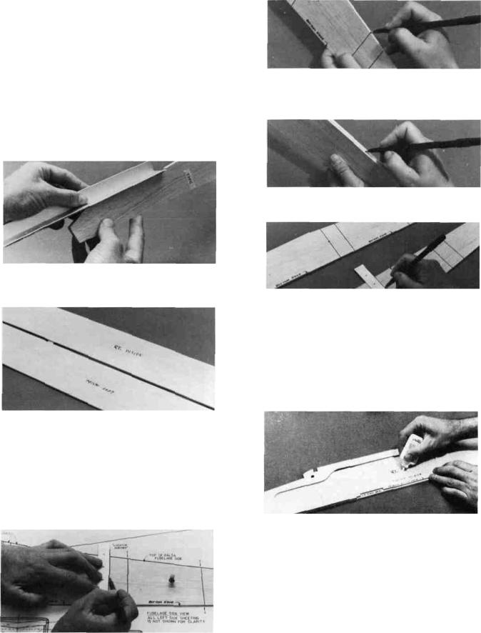
D 1. Take the two large 1/8" balsa fuselage sides and put them together. Carefully line them up along the bottom edge and the front. Tape them together with a few pieces of masking tape along the bottom edge to prevent them from moving. Now examine the other edges to make sure the two fuselage sides are exactly the same all around. If not, use a T-bar sander with 100 grit sandpaper to lightly sand the edges to match.
D 2. Now, with the tape still in place along the bottom edge, let the two sides fall open and write "Rt inside" and "Left inside" as shown here.
D 3. Tape the fuselage plan to your building surface.
D 4. Lay the right fuse (fuselage) side on the plan, and carefully position it so the bottom edge and the nose line up with the plan. Insert a few pins or tape to hold it in place.
D 5. Using the "locator arrows", a straightedge and a pen, draw six vertical lines on the fuse side as shown. Press lightly to avoid damaging the balsa.
D 6. Remove the fuse side from the plan and make small marks on the top and bottom edges, where the lines end.
D 7. Put the two fuse sides together (inside to inside), and line them up carefully. While holding them together, transfer the edge marks over to the left fuse side edges as shown here.
D 8. Now draw lines on the left inside fuse side, using the edge marks and a straight edge.
D 9. Lay the large 1/8" ply fuse doubler on the right inside fuse side and position it to line up at the nose and bottom edge. The part of the doubler which is behind the L.G. plate area must be exactly 1/8" above the bottom edge of the fuse side. Use a piece of 1/8" balsa (such as the "windshield" piece) to check this spacing. When you are satisfied that the doubler is correctly lined up, apply thin CA glue all around the edges while holding the doubler in place. Use enough glue to make sure it flows under the plywood to make a good bond.
D 10. Position the upper and lower "lock plates" and the stab saddle doublers on the right fuse side, using the vertical guidelines previously drawn. The upper lock plates and stab saddle doubler must be even with the top edge of the fuse side. The three lower lock plates must be positioned 1/8" above the bottom edge of the fuse side. Use a piece of 1/8" balsa as a spacer to aid in correct positioning of the bottom lock plates. Glue these parts in place with thin CA.
(See photo on next page.)

D 11. Notice that the 1/8" balsa fuse side has two slightly rounded corners at the front of the "hatch" area and at the front of the "stab saddle" area. Using an X-Acto knife, cut away these rounded comers to match the doublers.
D 12. Turn the fuse side over and lay the 1/8" balsa upper fuse side in place on the doubler, lining up the curved "windshield" edge. Apply glue all around the edges of this upper fuse side.
LI 13. Draw a straight line connecting the front edge of the front slots in the fuse doubler.
D 14. Lay the 1/4" balsa lower tripler in place on the fuse doubler, and line it up with the line just drawn and the edge of the doubler Glue the lower tripler in place with thin CA all around the edges.
D 15. Use one of the 3/8" ply engine beams as a spacer to position the 1/4" balsa upper tripler. Move the upper tripler forward or back until it lines up with the line you drew in Step 13.
D 16. Remove the 3/8" ply spacer, then glue the upper tripler in place with thin CA all around the edges.
D 17. Glue the fuselage doubler, upper and lower lock-plates, upper fuse side, stab saddle doublers and the 1/4" balsa triplers to the left inside fuselage side. Be sure to follow the same procedure as set forth in steps 9-16 when doing so, but don't make two Rt. fuse sides!
D 18. Drill or cut out the 5/16" holes in the fuse sides for the wing hold-down dowels. If you use a drill, lay the fuse side on a wood block for a backing to drill into, which will prevent the balsa from tearing.
ASSEMBLE THE FUSELAGE
D 1. Before assembling the fuselage, make sure that the following parts are set out within easy reach: both fuse sides with doublers and triplers securely glued on; formers F-l through F-6; 1/8" ply fuse bottom; 3/8" ply L.G. (landing gear) plate; 1/8" balsa fuse bottom; the tapered balsa "fuse tail wedge" and the six #62 rubber bands provided.

Note: In the next steps you will assemble the fuselage without glue! The interlocking parts enable you to do this so you can get everything together, make sure the parts fit properly, check for straightness and make adjustments if necessary. Then you will glue everything together by applying thin CA.
D 2. Make the "firewall" (Former F-l) by gluing together the two 1/8" plywood parts which are marked "F-l". Use 5 minute epoxy for thisjob. After the epoxy has hardened, drill four 1/8" holes at the marks for the nose gear bearing mounting holes.
D 3. Lay the right fuse side flat on the work surface. Insert formers F-l and F-2 into their respective slots in the right fuse side doubler.
D 4. While holding F-l and F-2 upright, lay the left fuse side in place on these formers. Now put the 1/8" ply fuse bottom in place in the slots provided.
D 5. Holding these five parts together with one hand, slide two #62 rubber bands over the nose, leaving one around F-l and one around F-2.
Note: Notice that the fuselage has now become somewhat rigid and square. Before proceeding make sure that the tabs in F-l, F-2 and the fuse bottom are properly inserted into the slots in the fuse doublers. Position the fuselage in its normal (upright) position while inserting the other formers in the next steps.
D 6. Put former F- 3 in place and secure by sliding a rubber band around the fuselage from the rear.
D 7. Slide another rubber band around the fuse to the F-4 location, pulling the fuse sides together. Now work F-4 into place in the lock-plate notches.
(See photo at top of next column.)
D 8. Put F-5 and F- 6 in place in the lock-plate notches and secure with rubber bands.
D 9. Note that the rear end of the stab saddle doublers touch, preventing the rear ends of the fuse sides from coming together. Using your T-bar, sand the rear portions of both the stab saddle doublers as shown until the rear ends of the fuse sides nearly touch.
D 10. Turn the fuselage upside down and place the 3/8" ply L.G. plate into the slots provided. Secure with masking tape.
D 11. Now take the 1/8" balsa fuse bottom and carefully slide it in place, narrow end first, under the rubber bands, starting at F-3.
D 12. Finally, insert the tapered balsa fuse tail wedge, and secure with a small rubber band or masking tape.
D 13. Temporarily install the 3/8" ply engine beams and the 1/4" ply breakaway plates. Hold in place with masking tape. Now position your engine on the breakaway plates and your fuel tank behind F-l. Don't worry about exact fits at this time. While holding these parts in position, determine where to drill the holes in F-l for the fuel lines and the throttle pushrod. (See photo and notes on next page.)

NOTE ON ENGINES: The engine mount
"breakaway plates" have been cut to an average width which will permit mounting almost any engine you choose. However, you may have to trim these plates slightly to fit your engine. The best way to do this is to sand or file away a little at a time from the inside edges of both breakaway plates until your engine fits between the plates.
NOTE ON FUEL TANK: The PT40 requires any 6 or 8 oz. fuel tank of your choice. Most tanks have three possible openings, one for fuel pickup, and two for the fill/vent lines. We recommend that you only use two lines. Run one line from the "klunk" pick-up to the fuel fitting on the engine carburetor and the other to the "pressure tap" fitting on the muffler.
D 14. Because you have not yet glued the fuse parts together, you may now carefully remove F-l and drill the holes for the fuel lines and throttle pushrod.
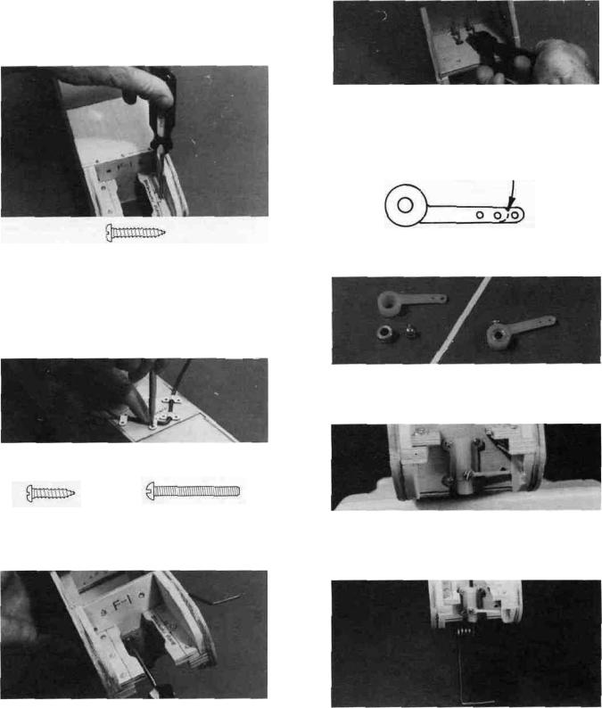
D 15. Insert four 4-40 blind nuts part-way into the 1/8" holes previously drilled. Insert them from the back side of F-l. Apply one drop of thick CA glue under the wide part of each nut, then immediately press them firmly in place with a pliers or a vise.
4-40 BLIND NUT
D 16. Replace F-l back into the fuse.
D 17. By now you should have decided which wing you are going to build, "Wing A" (without ailerons), or "Wing B" (with ailerons). If you have chosen' "Wing A", find the four F-2A wing saddles and put them into the slots behind F-2 and in front of F-3. If you have chosen "Wing B", use the F-2B saddles.
D 18. Check your assembly of the fuselage, making sure that all former tabs are in their respective notches and all parts are in place. Set the fuselage assembly on the plan top view. Your fuse assembly should line up with the plan within 1/16". If not, something is wrong and you should try to straighten it out. If the alignment is far off and you can't find the problem, consult with an experienced model builder to correct the problem before proceeding.
D 19. Lay down a 50" long piece of waxed paper to protect your building surface. Set the fuselage assembly upright (in its normal position) on the waxed paper. With everything in its proper place, apply thin CA glue to all the joints, around the formers and along the bottom. Wait a minute for the glue to set, then apply thick CA to the joints to make sure a good bond exists, especially in the joints that do not fit perfectly. Note: The use of "Zip Kicker" or other CA glue accelerator will be helpful when using thick CA to fill any large gaps.
D 20. Remove the rubber bands from the fuselage. In the above step you may have glued the rubber bands to the wood in some places. If so, just cut the rubber away from the wood with an X-Acto knife.
INSTALL THE WINDSHIELD
AND HATCH
D 1. Put the 1/2" balsa triangle windshield brace in place and apply thin CA glue.
D 2. Sand the 1/2" balsa triangle to match the curve on the fuse sides.
D 3. Sand the bottom edge of the l/8"balsa windshield at an angle so it will rest flat on the fuse
sides.
D 4. Apply thick CA to the 1/2" balsa triangle, then immediately place the windshield in position, holding the bottom against the triangle.
10 |
(See photo, top of next page.) |
D 5. Wet the top surface of the windshield so the wood will bend without breaking.
D 6. Apply thick CA to the top of F-2 and the fuse sides where the windshield will contact, then immediately bend the windshield down and hold until the glue sets
D 7. Trim any excess windshield even with the back edge of F-2.
D 8. Taper the rear edge of the 1/8" ply hatch to fit the windshield as shown on the fuse plan side view.
D 9. Find the piece of 1/8" ply that you punched out of F-5. This is used as the hatch tongue. Glue the hatch tongue to the bottom of the 1/8" ply hatch with thick CA. Let the hatch tongue extend about 1/2" beyond the back edge of the hatch.
D 10. Draw a guideline 1/8" back from the front edge of the hatch. This is the centerline of the three hatch hold down screws.
D 11. Holding the hatch firmly in position, drill three 1/16" holes along the guideline •
D 12. Remove the hatch and re-drill the holes in the hatch only to 3/32". Then attach the hatch to the fuse with three #2 x 3/8" screws. (See photo, top of next column.)
MOUNT THE ENGINE BEAMS AND BREAKAWAY PLATES
D 1. Glue the 3/8" ply engine beams in place using 5 minute epoxy. With a tissue, wipe off any excess epoxy that squeezes out when sliding the beams into the slots. Allow the epoxy to fully cure before disturbing the beams.
D 2. Holding the 1/4" breakaway plate under the 3/8" ply beam, draw a line on the breakaway plate to mark the edge of the beam.
D 3. Now place the breakaway plate on top of the beam and while holding the plate firmly in place, drill three 3/32" holes as shown, drilling down through the breakaway plate and the beam. Do this for both plates and beams.
11
D 4. Remove the breakaway plates and re-drill the holes in the breakaway plates only to 1/8".
D 5, Fasten the breakaway plates to the beams using six #4 x 5/8" screws.
#4x5/8" SCREW
INSTALL THE LANDING GEAR
D 1. Turn the fuselage upside down and position the 5/32" wire main L.G. (landing gear) on the ply L.G. plate. Set the four nylon L.G. straps in place and mark the location for the eight screw holes. Drill 3/32" (or slightly smaller) holes at the marks.____
D 2. Temporarily mount the main LG using the nylon straps and the #4 x 1/2" screws.
PREPARE THE NOSE GEAR
D 1. Referring to the steering arm drawing here, cut off about 3/16" of the steering arm so it will clear the fuse triplers. Drill out the end hole to 5/64"diameter for pushrod wire clearance.
TRIM 3/16" HERE
D 2.Assemble the nose gear steering arm which consists of a nylon arm, a 5/32" wheel collar and a 6-32 x 3/16" screw.
D 3. Place the steering arm assembly into the nose gear bracket making sure that the wheel collar opening on the steering arm is down and the screw is facing out.
11
#4x1/2" SCREW |
4-40x1" BOLT |
D 3. Temporarily mount the nylon nose gear bearing using four 4-40 x 1" bolts screwed into the 4-40 blind nuts previously installed.
D 4. If you are a young person, you should ask an adult to help you with the following step:
Using a side cutter, cut off the excess bolt length sticking out behind F-l. You must wear eye protection when doing this! Note: An alternate method is to mark the bolts with an indelible marker, remove them from F-l, and cut them off at the marks with a side cutter, hacksaw or a Dremel cut-off wheel.
(See photo, top of next column.) |
12 |
|
D 4. Referring to the nose gear diagram on the plans, slide the nose gear wire through the holes in the nose gear bearing and wheel collar/steering arm. Tighten the screw, making sure the steering arm is at the angle shown on the top view of the fuselage.
CUT THE NOSEGEAR PUSHROD OPENING
D 1. Mark and drill a 1/8" hole through Former F-l in the position shown on the F-l drawing on the plan. This hole is for pushrod clearance.
See photo, top of next page
 Loading...