


GPMA0170
WARRANTY
Great Planes Model Manufacturing Co. guarantees this kit to be free from defects in both
material and workmanship at the date of purchase. This warranty does not cover any
component parts damaged by use or modification. In no case shall Great Planes' liability
exceed the original cost of the purchased kit. Further, Great Planes reserves the right to
change or modify this warranty without notice.
In that Great Planes has no control over the final assembly or material used for final
assembly, no liability shall be assumed nor accepted for any damage resulting from the use by
the user of the final user-assembled product. By the act of using the user-assembled product
the user accepts all resulting liability.
If the buyer is not prepared to accept the liability associated with the use of this
product, he is advised to immediately return this kit in new and unused condition to the
place of purchase.
READ THROUGH THIS INSTRUCTION
BOOK FIRST. IT CONTAINS IMPORTANT
INSTRUCTIONS AND WARNINGS
CONCERNING THE ASSEMBLY AND
USE OF THIS MODEL.
P.O. BOX 788 URBANA, ILLINOIS 61801 (217) 398-8970
ENTIRE CONTENTS © Copyright 1992, HOBBICO, INC.
SKY6P03 V1.1
TABLE OF CONTENTS
INTRODUCTION.......................................... 3
PRECAUTIONS............................................ 3
OTHER ITEMS REQUIRED.......................... 4
SUPPLIES AND TOOLS NEEDED ............... 4
DECISIONS YOU MUST MAKE NOW.......... 5
ABBREVIATIONS
TAIL FEATHERS.......................................... 7
BUILD THE FIN AND RUDDER.................... 7
BUILD THE STABILIZER AND ELEVATORS. 8
TEMPORARILY INSTALL HINGES ............. 10
FUSELAGE ASSEMBLY.............................. 11
PREPARE FUSE SIDES............................... 11
ASSEMBLE FUSELAGE.............................. 16
DRILL ENGINE MOUNT............................... 16
FIT FUEL TANK AND
FUELPROOF TANK COMPARTMENT......... 16
INSTALL TAIL PUSHRODS.......................... 18
SOLDERING HINTS..................................... 19
ASSEMBLE THE CABANES........................ 20
SETTING THE TOP WING INCIDENCE ...... 21
SOLDERING THE CABANE
WIRES TOGETHER..................................... 22
INSTALL TOP SHEETING............................ 23
ATTACH THE TAIL SURFACES
TO THE FUSELAGE
.........................................
....................................
5
26
GLUE ELEVATOR AND RUDDER HINGES . 64
GLUE CANOPY IN PLACE .......................... 64
ASSEMBLE WHEEL PANTS........................ 65
STRENGTHEN AND FUEL PROOF ............ 66
WING SEATING........................................... 67
FINAL HOOK-UPS....................................... 67
CONTROL THROWS....................................68
BALANCE YOUR MODEL............................ 68
FINAL CHECKS........................................... 68
PRE-FLIGHT................................................69
CHARGE THE BATTERIES.......................... 69
FIND A SAFE PLACE TO FLY...................... 69
GROUND CHECK THE MODEL
RANGE CHECK YOUR RADIO.................... 70
ENGINE SAFETY PRECAUTIONS
AMA SAFETY CODE................................... 70
FLYING........................................................ 71
2-VIEW DRAWING....................................... 72
..................
..............
69
70
Metric Conversion Chart
WING
...........................................................
SPARS......................................................... 28
BUILD THE BOTTOM WING ....................... 29
BUILD THE TOP WING................................ 31
JOIN THE TWO TOP WING HALVES .......... 33
INSTALL THE TOP WING SHEETING ......... 37
FINISH THE TOP WING............................... 42
BUILD THE INTERPLANE STRUTS ............ 44
JOIN AND SHEET THE BOTTOM WING .... 46
FINISH THE BOTTOM WING....................... 49
FINISH AND ATTACH THE WING................ 55
FINAL ASSEMBLY...................................... 57
BUILD THE BOTTOM WING FAIRING......... 57
INSTALL THE LANDING GEAR
ASSEMBLE THE COWL .............................. 59
PREPARE THE CANOPY
INSTALL THE CONTROL HORNS............... 62
MAKE THE TOP WING LOCK...................... 63
BALANCE THE AIRPLANE LATERALLY...... 63
FINAL SANDING.......................................... 64
COVERING.................................................. 64
GLUE THE AILERON HINGES .................... 64
...................
............................
28
58
62
Inches x 25.4 = mm (conversion factor)
1/64" = .4mm
1/32" = .8mm
1/16" = 1.6mm
3/32" = 2.4mm
1/8" = 3.2 mm
5/32" = 4 mm
3/16" = 4.8mm
1/4" = 6.4 mm
3/8" = 9.5 mm
1/2" = 12.7mm
5/8" = 15.9mm
3/4" = 19mm
1" = 25.4mm
2" = 50.8
3" = 76.2 mm
6" = 152.4mm
12" = 304.8mm
15" = 381 mm
18" = 457.2mm
21" = 533.4mm
24" = 609.6 mm
30" = 762 mm
36" = 914.4mm
mm
-2-
WARNING! THIS IS NOT A TOY!
THIS IS NOT A BEGINNER'S AIRPLANE!
This R/C kit and the model you will build is not a toy! It is capable of serious bodily harm and
property damage IT IS YOUR RESPONSIBILITY AND YOURS ALONE — to build this kit correctly, to
properly install all R/C components and flying gear (engine, tank, pushrods, etc) and to test the model
and fly it only with experienced, competent help, using common sense and in accordance with all safety
standards as set down in the Academy of Model Aeronautics Safety Code It is suggested that you join
the AMA and become properly insured before you attempt to fly this model IF YOU ARE JUST
STARTING R/C MODELING, CONSULT YOUR LOCAL HOBBY SHOP OR WRITE TO THE ACADEMY
OF MODEL AERONAUTICS TO FIND AN EXPERIENCED INSTRUCTOR IN YOUR AREA.
Academy of Model Aeronautics
1810 Samuel Morse Dr.
Reston,VA 22090 (703)435-0750
Please inspect all parts carefully before
starting to build! If any parts are missing,
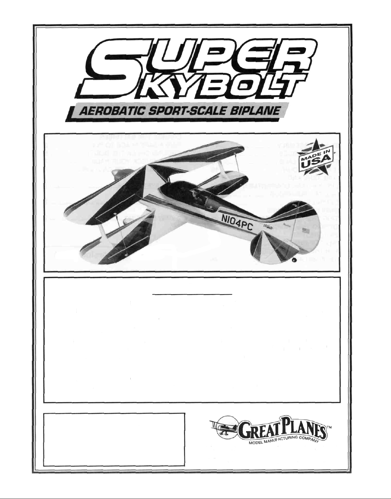
INTRODUCTION
Congratulations and thank you for
purchasing the Great Planes SUPER SKYBOLT'
The skybolt incorporates several new design
features never before found in a biplane kit The
revolutionary wing attachment system makes it
incredibly easy to assemble and disassemble at
the field using only a screwdriver It also features
several new construction techniques that make it
the easiest and straightest building biplane ever!
broken or defective, or if you have any
questions about building or flying this
airplane, please call us at (217) 367-2069
and we'll be glad to help. If you are
calling for replacement parts, please look
up the part numbers and the kit
identification number (stamped on the
end of the carton) and have them ready
when calling.
PRECAUTIONS
The Great Planes Super Skybolt is a high
performance biplane that is modeled after the full
size Skybolt It not only looks beautiful, but it is
also the smoothest and most predictable flying
biplane we have ever flown However, this is not
a beginner's airplane! While the Super Skybolt
is not difficult to build and flies great, we must
discourage you from selecting this kit as your
first R/C airplane It is highly maneuverable, and
lacks the self-recovery characteristics of a good
basic trainer such as the Great Planes PT
Series airplanes On the other hand, if you are
confident with your flying skill and can safely
handle aileron airplanes such as the Great
Planes Ultra-Sport Series or Big Stick Series,
the Super Skybolt is an excellent choice If you
currently fly an aileron airplane, but you are
unsure about your ability to handle the Super
Skybolt, we recommend that you build and fly a
low-wing sport plane first.
1 You must build the plane according to the
plans and instructions. Do not alter or modify
the model, as doing so may result in an unsafe or
unflyable model In a few cases the plans and
instructions may differ slightly from the photos In
those instances you should assume the plans
and written instructions are correct Also, you
may notice a slight difference in length between
longer parts and the plans This is normal and is
caused by the plans expanding and shrinking with
the changing moisture content in the air Do not
modify the parts to fit the plan
2 You must take time to build straight, true and
strong IMPORTANT - Glue should never be
substituted for a good-fitting joint Take a little
extra time to get a good fitting joint and glue it
properly It will be stronger, neater, and much
lighter than a bad joint held together with a glob
of glue!
3-
3 You must use a proper R/C radio that is in first
class condition and meets the current AMA and FCC
requirements and the requirements of your local flying
club, the correct sized engine and correct
components (fuel tank, wheels, etc.).
4 You must properly install all R/C and other
components so that the model operates properly on
the ground and in the air.
5. You must test the operation of the model before the
first and each successive flight to insure that all
equipment is operating, and you must make certain
that the model has remained structurally sound.
6 You must fly the model only with the competent
help of a well experienced R/C pilot if you are not
already an experienced and knowledgeable R/C pilot
at this time.
Note: We, as the kit manufacturer, provide
you with a top quality kit and great
instructions, but ultimately the quality and
flyability of your finished model depends on
how you build it; therefore, we cannot in any
way guarantee the performance of your
completed model, and no representations are
expressed or implied as to the performance
or safety of your completed model.
Remember: Take your time and follow directions
to end up with a well-built model that is straight
and true.
OTHER ITEMS REQUIRED
D Four-channel radio with 4 or 5 servos
D Propellers (Top Flite® Power Point™ recommended
- see engine instructions for recommended sizes)
D 2-1/2" (63 5mm)Spinner
D 14 oz Fuel Tank
D Iron-on Covering Material (Top Flite MonoKote®
recommended)
D Fuelproof Paint for wheel pants and cowl
NOTE Top Flite has paint available that matches
Super MonoKote, and is available in convenient
spray cans
D Silicone Fuel Tubing
D 1/16" (1 5mm) thick Wing Seating Tape
D Latex Foam Rubber Padding (Hobbico® 1/4"
recommended )
D Plastic Pilot: Williams Bros. #185 Sport 2-1/2"
Scale
D 2-3/4" (70mm) Main Wheels
D 1-1/4"(32mm)Tail Wheel
D 22 Hinges*
D 2 - Servo extensions (each 24" long) req. for
ailerons on both wings
D 3/32" (2 5mm)Wheel Collars - 2 required for tail
wheel
D #64 Rubber Bands
SUPPLIES AND TOOLS NEEDED
D 2 oz Thin CA Adhesive
D 2 oz Medium or Thick CA Adhesive
D 2 5 oz 15-Minute Epoxy
D Hand or Electric Drill
D Drill Bits 1/16, 3/32", 5/32", 3/16", 1/4", & 19/64"
D Sealing Iron (Hobbico or Top Flite recommended)
D Heat Gun (Hobbico or Top Flite recommended)
D Razor Saw
D Hobby Knife, #11 Blades
D Pliers
D Screw Drivers
D T-Pins
D Straightedge
D Masking and/or Strapping Tape (Required for
construction)
D Sandpaper (coarse, medium, fine grit)*
D T-Bar Sanding Block (or similar)
D Waxed Paper
D Lightweight Balsa Filler ( Hobbico HobbyLite™
recommended)
D Petroleum Jelly (Vaseline)
D IsopropyI Rubbing Alcohol (70%)
D Spray Adhesive (optional) (3M "77")
D Dremel Moto Tool or similar (optional)
*NOTE: There are many types of good hinges on the
market, and everyone has their personal preferences;
therefore, hinges have not been included in this kit.
The current favorite of many modelers is the
laminated hinge that permits hinge slotting with a
hobby knife, and gluing with thin CA adhesive.
*NOTE: On our workbench, we have four 11" T-Bar
sanders, equipped with #50, #80, #700 and #150-grit
We also keep some #320-
grit wet-or-dry sandpaper handy for finish sanding
before covering.
-4
DECISIONS YOU MUST MAKE NOW
ENGINE AND MOUNT
The recommended engine for the SUPER
SKYBOLT is a 61* - 90 cubic inch (10 - 15cc)
displacement 2-cycle or a 90 - 1 20 cubic inch
(15-20cc) displacement 4-cycle The
instructions and plans show an OS Max
61(10cc) SF and an OS Max 1 20 (20cc)
Surpass being installed It you are using an
engine other than one of these, be sure to
double check all measurements before gluing or
cutting things that have to do with the engine.
*NOTE: Performance may be marginal if a non-
Schnuerle-ported .60 cu.in. 2-Cycle engine
is used
This kit includes a new Great Planes adjustable
.40 - .70 engine mount (EM4070) that fits most
40 - 61 (2-Cycle) engines and 40 - 70 (4-cycle)
engines If the supplied mount does not fit your
engine, it may be necessary to purchase a
different mount (check with your hobby dealer).
POSSIBLE RADIO
INSTALLATIONS
The Super Skybolt can utilize either one
or two aileron servos We recommend that you
use two aileron servos and build the top wing
with ailerons This is the most maneuverable
configuration and you can always reduce the
control throws to achieve the sensitivity you
desire When using two aileron servos, the
servos are mounted in the bottom wing, directly
in front of the ailerons and control slop is
virtually eliminated If you prefer to use only
one aileron servo, we suggest that you do not
put ailerons on the top wing due to the inherent
top aileron sloppiness The plans show both
methods of construction.
COMMON ABBREVIATIONS USED
IN THIS BOOK AND ON THE
PLANS:
Elev = Elevator
Fuse = Fuselage
LE = Leading Edge (front)
LG = Landing Gear
Ply = Plywood
Stab = Stabilizer
TE = Trailing Edge (rear)
" = Inches
Tri = Triangle
TYPES OF WOOD
GET READY TO BUILD
D 1 Unroll the plan sheets and reroll them inside
out to help them lie flat.
D 2 Remove all parts from the box As you do,
determine the name of each part by comparing it
with the plan and the parts list at the back of this
book. Using a felt tip pen, write the part name or
size on each piece to avoid confusion later Use
the die-cut part patterns shown on page 6 to
identify the die-cut parts and mark them before
punching out Save all leftover pieces. If any of
the die-cut parts are difficult to punch out, do not
force them' Instead, first cut around the parts with
a hobby knife After punching out the die-cut parts,
use your T-Bar or sanding block to lightly sand the
edges to remove any die-cutting irregularities.
BALSA
BASSWOOD
PLYWOOD
D 3 As you identify and mark the parts, separate
them into groups, such as fuse (fuselage), wing,
fin and stab (stabilizer), and hardware.
-5-
DIE-CUT PATTERNS
-6-
TAIL FEATHERS
BUILD THE FIN AND RUDDER
D 1. Tape the fuselage side view portion of the
plan down onto your flat work surface Tape a
piece of waxed paper over the fin and rudder
portion of the plan.
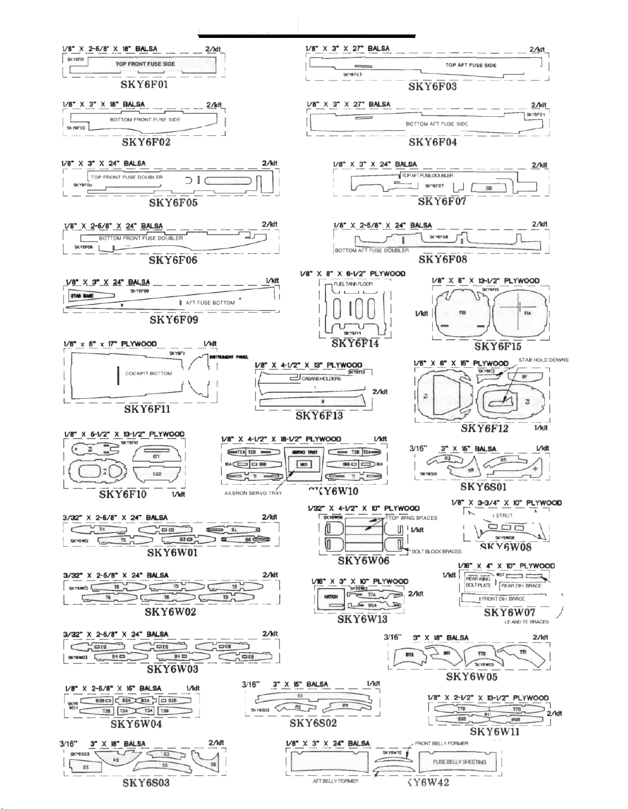
D 2 Working over the plan, cut and assemble the
fin and rudder framework using the die-cut 3/16"
balsa fin and rudder parts (SKY6S01 and
SKY6S02) and the 3/16" x 3/4" x 24" balsa sticks
(SKY6S05) as shown in the photo Sort through
the 3/16" x 3/4" x 24" balsa sticks and pick the
hardest two Use the hardest one later for the
stab trailing edge and use the next hardest one
here for the fin trailing edge Pin the parts in place
over the plan as you assemble them, but be
careful you don't glue the rudder to the fin
D 5 Using the plan as a guide, cut 3 pieces of
1/16" x 3" balsa from a 1/16" x 3" x 24" balsa
sheet (SKY6S06) to form the fin sheeting as
shown in the photo Glue these together and
quickly wipe off any excess glue with a paper towel
before it cures Sand both sides smooth and then
cut and sand the correct angle into the bottom of
the sheeting so you don't have to cut it after it's
installed on the fin Make sheeting for both sides of
the
fin.
HINT: Use new, sharp sandpaper when sanding
wood with glue joints in it The sharper grit will cut
through the glue much easier and produce better
results than worn out sandpaper
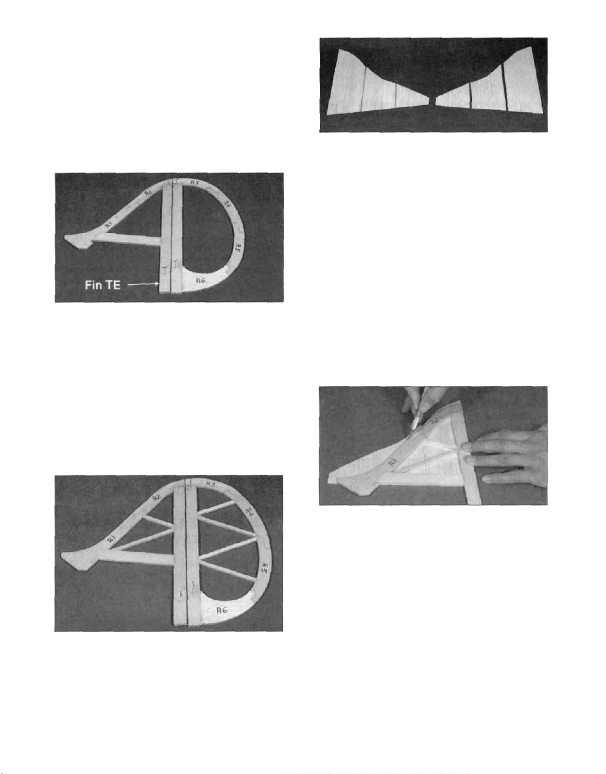
D 3. Cut the fin and rudder "ribs" from the 3/16" x
1/4" x 24" balsa sticks (SKY6S04). Glue these in
place with CA.
D 4. Sand both sides of the fin and rudder
smooth with a fine grit sanding block.
D 6 Glue the sheeting to one side of the fin.
Notice that the grain runs vertical on the fin.
Keep the fin flat while attaching the sheeting After
the side sheeting is installed, trim it flush with the
leading and trailing edges of the fin NOTE: Do not
cut through the sheeting and into the
framework. Always cut into the work surface'
D 7 Glue the other side sheeting in place Be sure
the fin is kept flat until the glue cures Trim and sand
the sheeting flush with the leading and trailing
edges of the framework Carve and sand the
leading edge to a nice rounded shape as shown on
the plans, but keep the trailing edge square.
-7-
D 8. Draw a centerline all around the edges of the
rudder. Sand the rudder to a taper as shown on
the fuselage top view. The framework should
end up approximately 3/32" thick at the trailing
edge. Refer to the centerline you drew to keep the
rudder symmetrical.
D 9. Using the plan as a guide, cut a 1/16" x 3" x
24" balsa sheet (SKY6S06) in half to form the
rudder sheeting as shown in the photo. Glue
these together and sand both sides smooth. Make
sheeting for both sides of the rudder. Cut one end
of the sheeting perpendicular to a long edge.
D 12. Cut two 4" long pieces of 1/16" x 1-3/8"
balsa sheeting from the 1/16" x 1-3/8" x 24" hard
balsa sheeting (SKY6S07). Glue these to both
sides of the rudder next to the sheeting on R6.
D 13. Use a sanding block with medium (150) grit
sandpaper to sand both sides of the rudder
smooth. Carve and sand the rudder trailing edge to
a nice rounded shape and the leading edge to a
"V" shape as shown on the plan.
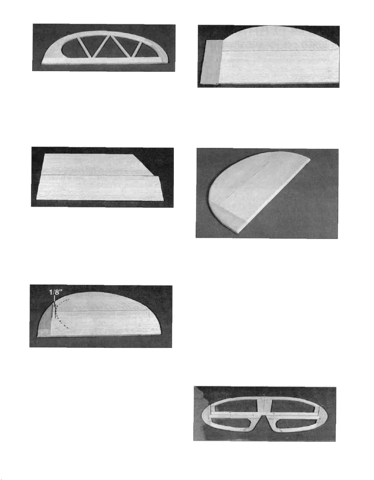
D 10. Glue the sheeting to one side of the rudder
so the perpendicular edge overlaps onto R6
approximately 1/8". The rest of R6 is not sheeted
until later. Keep the rudder flat while attaching the
sheeting. After the sheeting is installed, trim it flush
with the outside edges of the framework.
D 11. Glue the other side sheeting in place so that
it too only overlaps approximately 1/8" onto R6. Be
sure the rudder is kept flat until the glue cures.
Trim and sand the sheeting flush with the leading
and trailing edges of the framework.
BUILD THE STABILIZER AND
ELEVATORS
D 1. Tape the fuselage top view portion of the
plan down onto your flat work surface, and cover
the stabilizer portion of the fuselage top view with
wax paper.
D 2. Assemble the stab and elevator framework
over the plan, using the die-cut 3/16" balsa stab
-8-
parts (SKY6S02 and SKY6S03) and the 3/16" x
3/4" x 24" balsa sticks (SKY6S05) Use the
hardest 3/16" x 3/4" stick for the stab trailing edge
Pin the parts in place over the plan as you
assemble them but be careful not to glue the
elevator to the stab
D 3 Cut the stab and elevator "ribs" from the
3/16" x 1/4" x 24" balsa sticks (SKY6S04) Glue
these in place with CA.
D 4 Use a sanding block with medium (150) grit
sandpaper to sand the edges and both sides of
the stab and elevator smooth Carefully draw a
centerline all around the edges of the stab and
elevator This will make it easier to maintain
symmetry when sanding later.
D 7 Glue the other side sheeting in place Be
sure the stab is kept flat until the glue cures Trim
and sand the sheeting flush with the leading and
trailing edges of the framework NOTE: It is
essential to get a strong and complete bond
between the stab sheeting and the stab
framework, especially in the center, therefore,
we recommend using 30 minute epoxy when you
apply the last piece of sheeting Spread the epoxy
evenly but sparingly on the structure, to avoid
excess weight
D 8 Carve and sand the leading edge to a nice
rounded shape as shown on the plans, but keep
the trailing edge and the tips square
D 5 Glue two 1/16" x 3" x 24" balsa sheets
(SKY6S06) together (edge to edge) to form one
piece of stab sheeting Sand or trim the edge of
the sheets before gluing to obtain a good joint
between the two, without any gaps After the glue
is cured, sand both sides of the sheeting with a
fine grit sanding block Make sheeting for both
sides of the stab.
D 6 Thoroughly glue the sheeting to one side of
the stab Keep the stab flat while attaching the
sheeting After the sheeting is installed, trim it flush
with the edges of the stab.
D 9 Using a sanding block and coarse (80-grit)
sandpaper, sand both sides of the elevators to a
taper (see cross section on plans) The trailing
edge should end up approximately 3/32" wide
D 10 Cut four 1/16" x 2-5/8" x 24" balsa sheets
(SKY6S08) in half to form eight 12" long pieces
Glue these 12 sheets together to form four 5-1/4"
wide sheets Cut one end of each sheet so it is
perpendicular to the long edges Sand both sides
of these sheets smooth.
-9
D 11 Glue one 5-1/4" sheet to each elevator at
the angle shown on the plans and in the photo so it
overlaps onto S-6 approximately 1/8" Cut a corner
off the unused end of the sheet, and glue it at the
front tip of the elevator Trim the sheeting flush with
the edges of each elevator.
D 12 Glue the remaining sheeting in place on the
other side of each elevator so that it too overlaps
only approximately 1/8" onto S-6 Be sure the
elevator is kept flat until the glue cures Trim and
sand the sheeting flush with the edges of
the framework
TEMPORARILY INSTALL HINGES
D 1 Using the plan as a guide, mark the hinge
locations on the stab, elevators, fin and rudder
Designate one side of the stab as being the top and
one elevator as being "right" and the other as "left".
CAUTION!!!: You must use extreme care
when cutting hinge slots with a hobby
knife, to avoid cutting yourself! If the
balsa part breaks while you are pushing
on the knife, the blade could go into your
hand before you know it! A good
precaution is to wear leather gloves while
performing the following steps.
D 13 Cut four 4" long pieces of 1/16" x 1-3/8"
balsa sheeting from what is left of the 1/16" x
1-3/8" x 24" hard balsa sheeting (SKY6S07) Glue
these to both sides of each elevator, next to the
sheeting that stops at S-6
D 14 Sand the leading edge of the elevators to a
"V-shape" as shown on the plan Round off the
tips and the trailing edge, but keep the inside edge
(marked with an arrow) square
D 2 Cut the hinge slots on the centerlines you
drew earlier Our recommended hinge slotting
method is described below.
A Begin by carefully cutting a very shallow slit at
the hinge location The first cut is to establish
your cut in the right place, so concentrate on
staying on the line and don't cut too deeply.
B Make three or four more cuts in the same line,
going slightly deeper each time. As you make
these additional cuts, work on going straight
into the wood Continue this process while
"wiggling" the knife handle forward and
backward until the blade has reached the
proper depth for the hinge
C. Trial fit the hinge into the slot If the hinge is
difficult to push in, re-insert the knife and move
it back and forth in the slot a few times to
enlarge the slot Do not glue the hinges yet.
10
D 3 Refer to the plans and mark the location of
the tailgear (WBNT128) on the rudder Drill a 7/64"
hole in the rudder (the hole is drilled slightly
oversize to allow for positioning, and to create a
hard epoxy sleeve" around the wire) Then groove
the rudder leading edge to accept the tailgear wire
and the nylon bearing Mark the location of nylon
bearing on the fin and cut a slot for it.
FUSELAGE
ASSEMBLY
PREPARE FUSE SIDES
D D 1 Working over the fuselage side view
covered with waxed paper, trial fit a die-cut 1/8"
balsa top front fuse side (SKY6F01), and bottom
front fuse side (SKY6F02) together, sanding
slightly if necessary for a good fit Make sure they
line up with the plans, and glue them together
HINT: Using a hobby knife, sharpen the inside of
one end of a 1/8" diameter tube, and use it to cut
the groove in the leading edge of the rudder (and
ailerons if applicable)
D D 2 Trial fit a die-cut 1/8 balsa top aft fuse
side (SKY6F03) and a die-cut 1/8" balsa bottom
aft fuse side (SKY6F04) together Sand them
slightly if necessary to achieve a good fit, and
glue them together.
D D 3 Test fit the aft fuse side half in place
behind the front fuse side half Sand the two
halves if needed to get them to fit together tightly
and match up with the plans Glue them together
with CA Then sand both sides smooth with a
sanding block
D 4. Trial fit all these parts together using the
hinges Sand the aerodynamic balance" part of
the elevators to get them to match up with the
stab Do not glue the hinges until after covering
the surfaces.
D D 4 Working over the fuselage side view still
covered with waxed paper, trial fit a die-cut 1/8" balsa
top front fuse doubler (SKY6F05), and bottom
front fuse doubler (SKY6F06) together, sanding
slightly if necessary for a good fit Make sure they
line up with the plans, and glue them together.
11
D D 5. Trial fit a die-cut 1/8" balsa top aft fuse
doubler (SKY6F07) and a die-cut 1/8" balsa
bottom aft fuse doubler (SKY6F08) together.
Sand them slightly if necessary to achieve a good
fit, and glue them together.
D D 6. Test fit the aft fuse doubler half in place
behind the front fuse doubler half. Sand the two
halves if needed to get them to fit together tightly
and match up with the plans. Glue them together
with CA, and sand both sides of the doubler
smooth with a sanding block.
ASSEMBLE THE FUSELAGE
D 1. Trial fit the die-cut 1/8" ply formers F3, F4
and F5 (SKY6F10 and SKY6F12) to make sure
they fit into the appropriate slots in both fuselage
sides. If there is any excess glue in any of the fuse
doubler slots, clean it out with a hobby knife. If it is
necessary to trim any of the formers, be sure to
trim both sides of the formers the same amount to
keep them symmetrical.
D D 7. Position the doubler on top of the fuse
side and align their bottom and front edges. Glue
the doubler to the fuse side by applying thin CA
around all edges of the doubler, including the
lightning holes. Use plenty of thin CA to allow it to
wick into the joints as far as possible.
D D 8. Inspect all glue joints for gaps and add
thick CA if necessary to strengthen the joints.
D 9. Repeat the above steps to make another
fuse side and doubler. When gluing the doubler
to the fuse side, make sure you assemble a
RIGHT and a LEFT set of sides!
D 10. Place the two assembled fuse sides
together. Sand the edges as necessary to make
the two sides identical. Also sand the sides of
each assembly smooth with a fine sanding block.
D 2. Assemble formers F3, F4 and F5 between
the two fuse sides and use masking tape to pull
the fuse sides together. Make sure all the tabs are
seated in their notches, and add a drop or two of
thin CA to the top notches of each former. Use only
as much glue as required to tack things together.
We will come back and securely glue everything in
a few steps.
D 3. Fit the die-cut 1/8" ply belly former (BF)
(SKY6F12) into its notches to make sure it seats
all the way into the notches. Pull the fuse sides
together and glue the belly former into place.
Masking tape can be used to hold the fuselage
together while the glue cures.
12
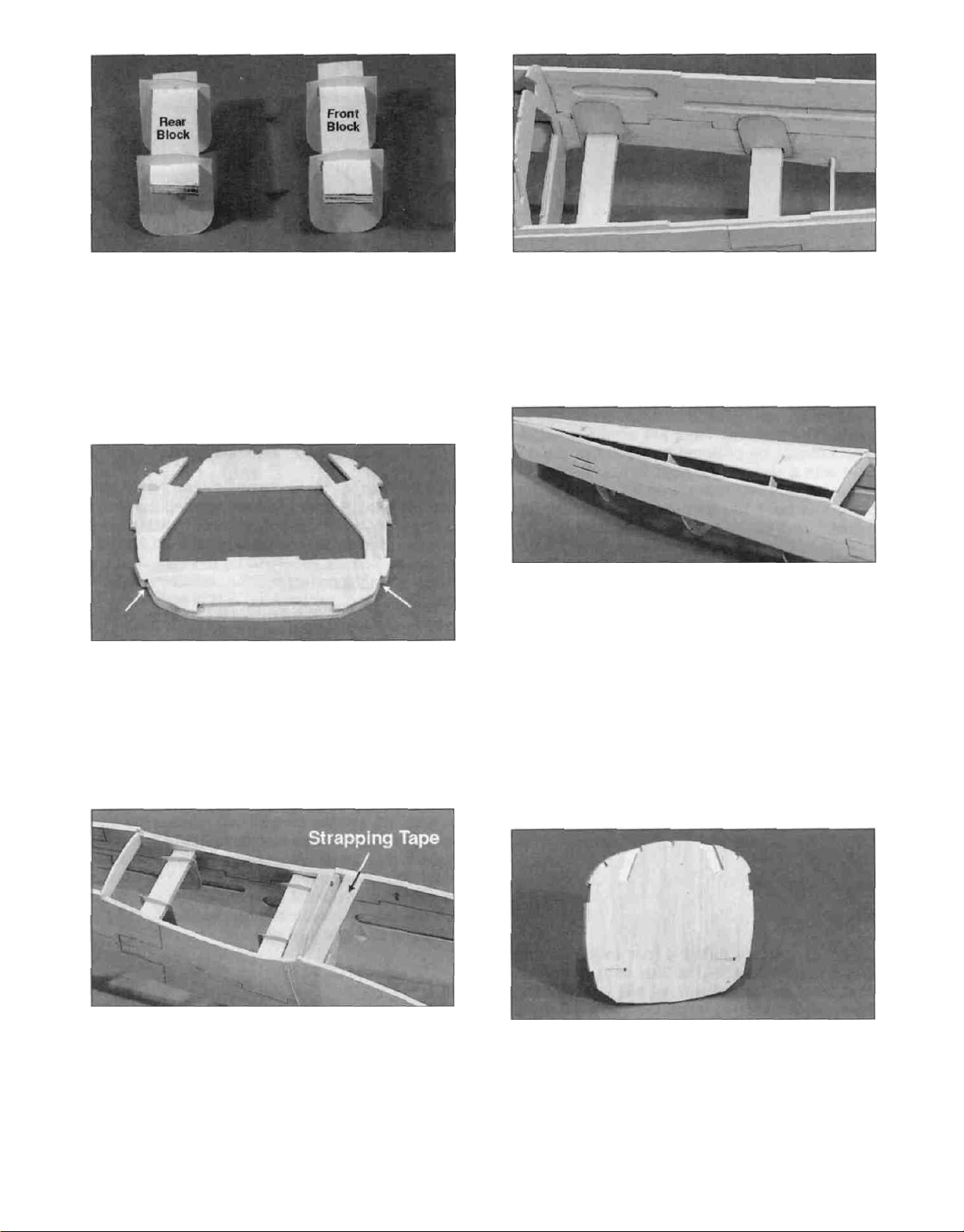
D 4. Slide two die-cut 1/32" ply bolt block braces
(SKY6W06) onto both the 1/4" ply front and rear
wing bolt blocks (SKY6F20 and SKY6F21). Notice
that the slant on the braces is at the front of the
rear block and the rear of the front block to clear
the wing saddle. The photo clearly illustrates this.
D 5. Glue die-cut 1/8" ply former LG2 (SKY6F10)
to one side of the die-cut 1/8" ply former F2
(SKY6F12) with thick CA. The bottom of the
interlocking tabs on both formers should line up as
shown in the photo.
D 7. Slide the 1/32" ply braces out against the
fuse sides and securely glue them in place with
thick CA or epoxy.
D 8. Glue the die-cut 1/8" balsa aft fuse bottom
(SKY6F09) in place with thin CA. The aft tip of the
bottom should be centered on the fuselage sides
and glued in place. The bottom will automatically
keep the aft portion of the fuselage straight. Go
over all the glue joints at formers F3, F4 and F5
and securely glue the fuse sides to the formers
with thin and then thick CA.
D 6. Position former F2 into place and apply CA
near the top notches. Carefully slide both wing bolt
blocks into their respective slots. Pull the fuse
sides together at the bottom of the former and use
strapping tape to hold them tightly against the
former. Make sure the bolt blocks are seated in
their notches, and apply thin CA around the blocks
and the former notches.
D 9. Use thick CA or epoxy to glue the die-cut 1/8"
ply formers F1A and F1B (SKY6F15) together to
form the firewall. NOTE: The embossed centerlines
must be showing on F1A. The interlocking tabs on
both formers should line up. . . but former F1B is
slightly larger than F1A, so just center it on F1A.
Wipe off any excess glue before it cures.
13
D 10 F1A has four lines embossed on it The two
short lines are the actual horizontal center of the
former The two crossing lines are offset to the left
(as viewed from the pilot's seat) of the horizontal
center to automatically put the spinner in the
center of the cowl when right thrust is built into the
plane The crossing lines are what the engine
mount should be centered on since this plane is
built with 2 degrees of right thrust Center the
engine mount on these lines as shown on the
plan, and mark the bolt locations through the
mount Drill 5/32" holes at the bolt locations
NOTE: This kit includes the new Great Planes
EM4070 Adjustable Engine Mount. To properly
position the mount, just slide the mounting
beams together and center the beams over the
embossed lines when marking the mounting
holes. There are "tick" marks on the side of the
mount to help you position it vertically.
D 11. If you are using a four cycle or other
engine/mount combination that does not require
four 9mm engine spacers but will use 6-32 blind
nuts, you will need to install the 1/8" x 2-3/4" x 23/4" plywood back plate (SKY6F31) on F1B.
Center it over the 5/32" holes and glue it in place.
Drill 5/32" holes through the back plate using the
holes you drilled earlier as guides NOTE If you
are using another engine mounting system, such
as vibration isolation type mounts, you may not
need the back plate The photos show a typical
.60-size glass filled mount being used.
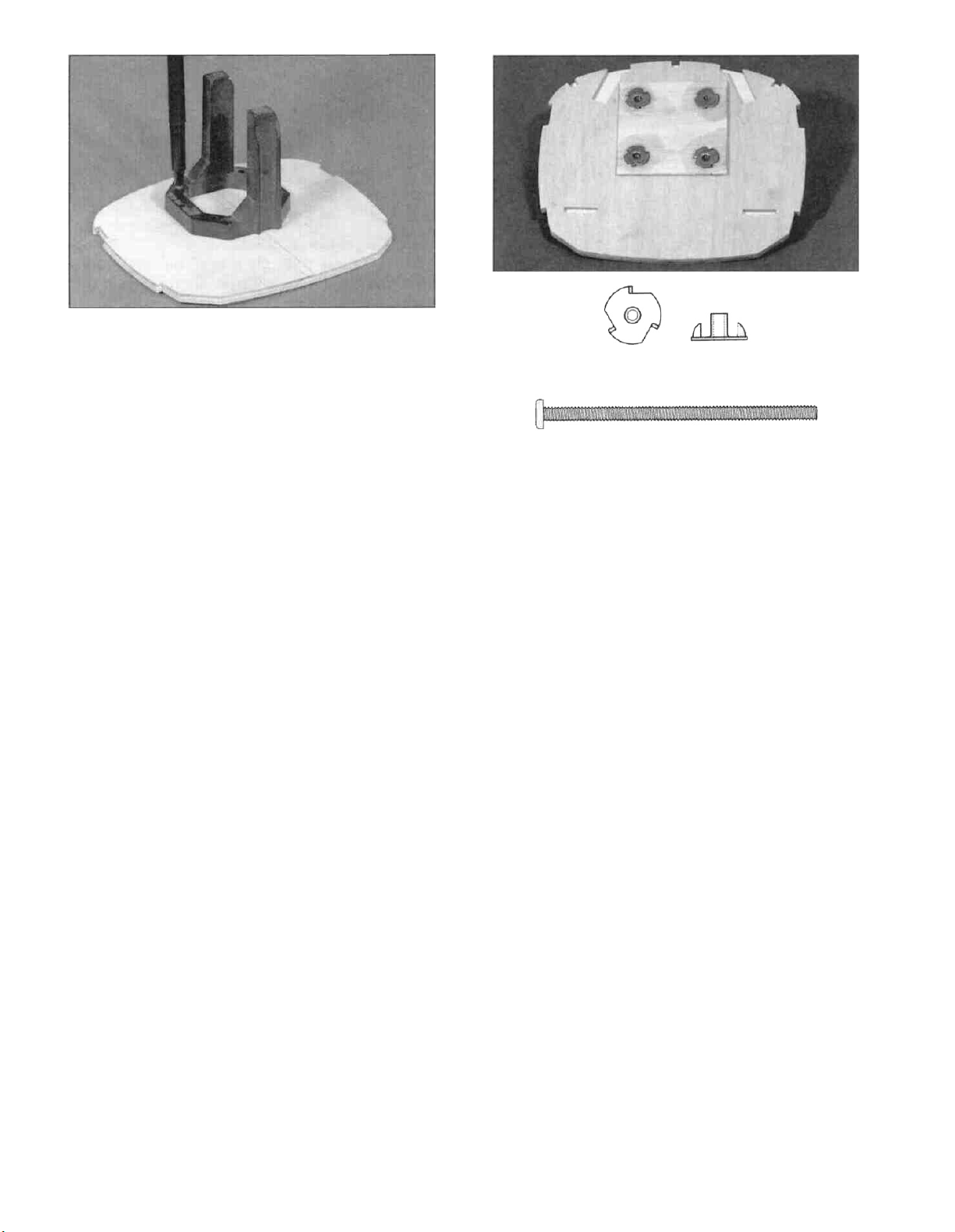
6-32 Blind Nut
6-32 X 2-1/2" Machine Screw
D 12 Press the four 6-32 blind nuts (NUTS003)
into the firewall from the back and tap them into
place with a hammer Temporarily attach the
engine mount to the firewall with the 6-32 x 2-1/2"
machine screws (SCRW071) to make sure the
holes are in the correct position Adjust the holes if
necessary, and glue the blind nuts in place.
D 13. Wet the outside of the fuselage sides from
F2 forward with water to help it bend around the
formers Test fit the die-cut 1/8" ply fuel tank floor
(SKY6F14), die-cut 1/8" ply former LG-1
(SKY6F10) and the firewall into place in the front
of the fuselage Notice that the fuel tank floor helps
set the right thrust and appears to be cut crooked
until you get everything assembled The firewall
should touch the front edge of the fuse side notch
on the left fuse side and the back edge of the
notch on the right fuse side.
The easiest way to assemble these parts is as
follows
D A Snap the back of the fuel tank floor into
its notches
NOTE: The tank floor when in position correctly,
should cause the firewall to slant to the RIGHT.
14
D B Tack glue the tab on the top of LG1 into the
fuel tank floor.
D C Tack glue the firewall onto the front of the
fuel tank floor
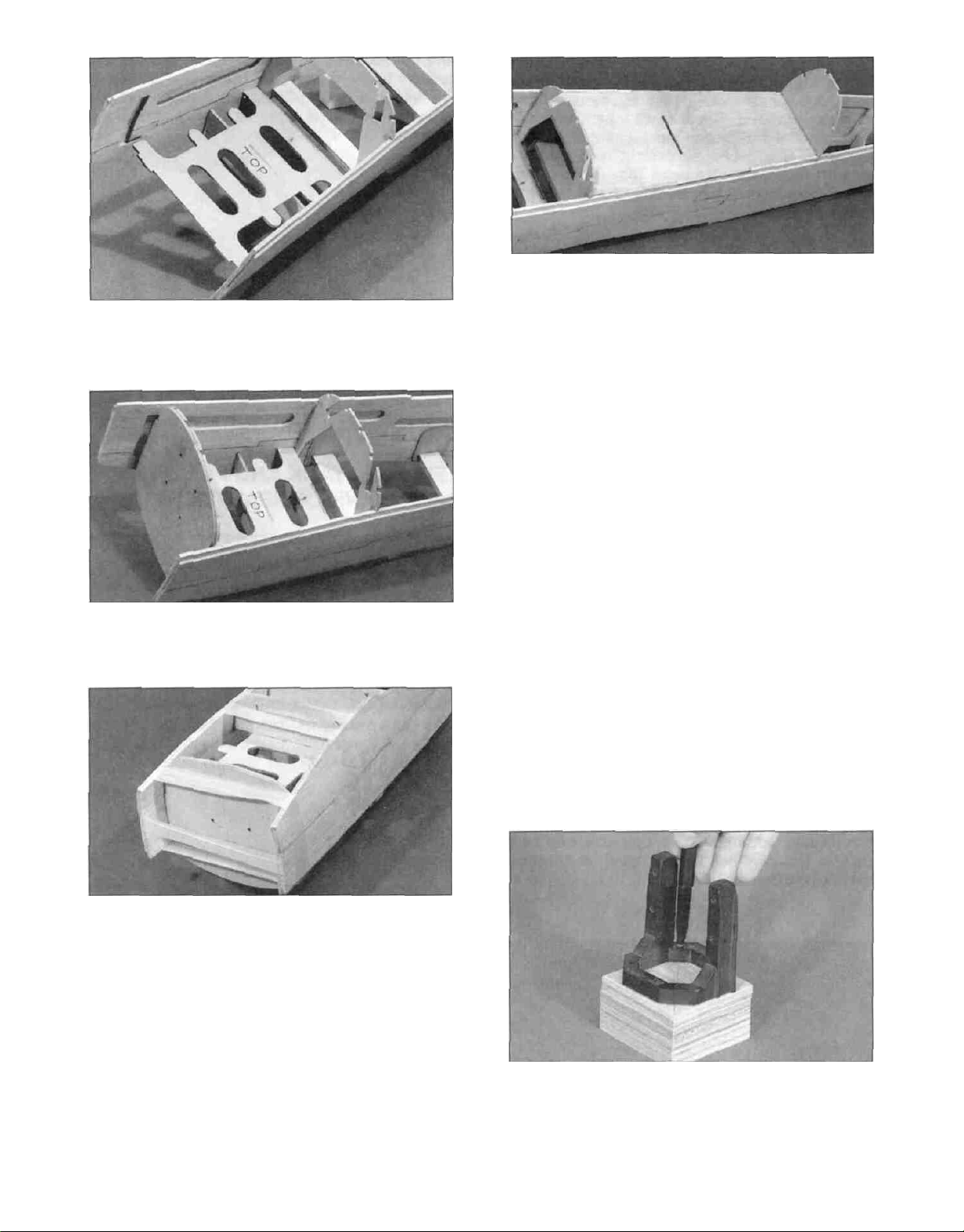
D 14 Snap the die-cut 1/8" ply cockpit bottom
(SKY6F11) in place by inserting the rear tab into
F3 and carefully sliding the front tab down into
place in F2 Glue the cockpit bottom to the fuse
sides and the formers.
Note: The engine mount shown in the
following photos may not be the mount
supplied in this kit.
D 15 Glue the required number of 9mm (3/8")
engine mount spacers (SKY6F27) together as
shown in the next photo You can lay your
engine/mount combination over the plans and
determine where the engine should be placed on
the mount and how many spacers should be used
We have determined that the following engines
usually require
D D Pull the fuse sides together and use
strapping tape to hold everything together
Securely glue everything in place with either epoxy
or CA If you are going to use CA, you can tape
everything first and thoroughly saturate the joints
with thin CA Then apply a generous bead of thick
CA around each joint
D E Included you will find a piece of 1/4" balsa
triangle for you to install on the back of the firewall
It should be pressed into the corners formed by the
fuse sides and the firewall.
The OS 61 SF requires 3 spacers
The OS 91 Surpass requires 1 spacer
The OS 1.20 Surpass requires no spacers
D 16 Center the engine mount on the face of the
spacers and mark where to drill the mounting
holes Drill 3/16" holes straight through all the
spacers you glued together (a drill press will be
helpful for this, if you have access to one)
15-
D 17. Mount your engine to your mount following
the manufacturer's recommendations. Refer to the
plans to make sure you get the engine positioned
far enough forward. The distance from the front of
the firewall to the front of the engine thrust plate
should be approximately 6-1/16" for a spinner
without overhang. Remove the engine. The
following instructions explain how to work with the
mount supplied.
DRILL ENGINE MOUNT
(Great Planes EM4070 or similar glass-filled mounts)
D 1. Hold the engine pointing straight ahead on
the mount (in the approximate location shown on
the plans) and mark the mounting hole locations
on the mount. At the marked locations, accurately
drill 7/64" (or #36) holes. NOTE: If you have
access to a drill press, use it for drilling these holes
to insure that they are drilled vertically.
and the required number of spacers. Glue the
spacers to the firewall and screw your engine to
the mount. If the 2-1/2" screws protrude into the
fuel tank compartment, cut them off flush with the
blind nuts.
FIT FUEL TANK AND FUELPROOF
TANK COMPARTMENT
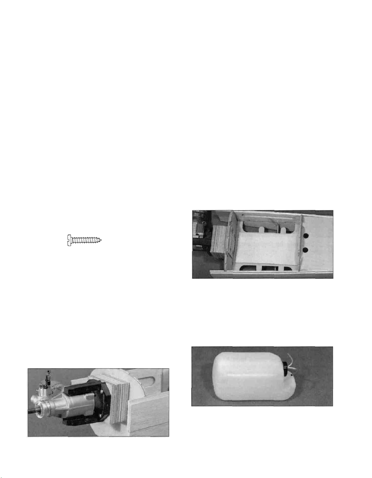
D 2. Now you may use one of the following
methods to attach your engine to the mount:
#6 X 3/4" Sheet Metal Screw
Method 1: Screw the #6 x 3/4" sheet metal
screws (provided in the kit) through the engine
mounting flange and into the mount. When first
installing these screws, put a drop of oil into each
screw hole.
Method 2: Cut threads into the holes you just
drilled using a 6-32 tap and tap wrench. If you use
this method, you'll have to supply your own bolts
(6-32 x 1" socket head cap screws) for attaching
the engine to the mount.
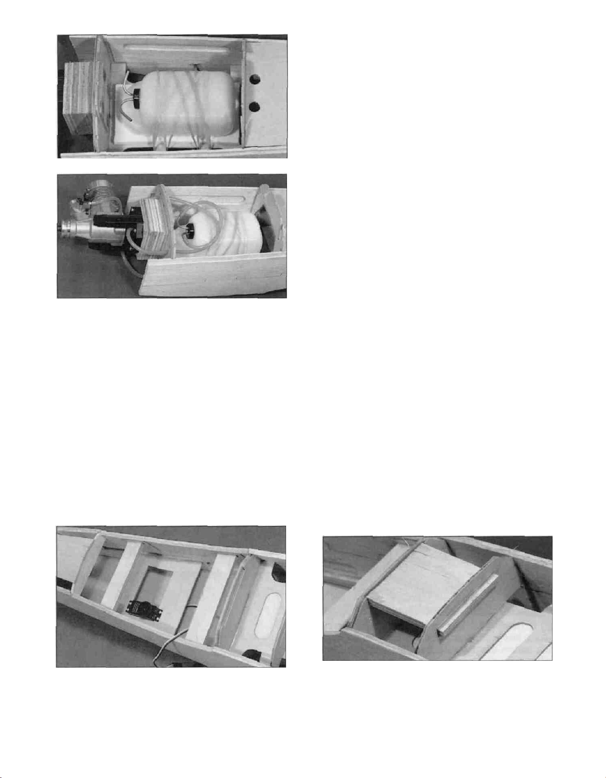
D 1. Cut a piece of 1/4" thick latex foam (not included)
into a 3" x 6" rectangle. Glue it to the ply tank floor to
help keep the fuel tank from vibrating excessively.
D 3. Attach the engine mount to the firewall using
the 6-32 x 2-1/2" machine screws (SCRW071)
D 2. Assemble your 14 oz. fuel tank according to
the tank and engine manufacturer's instructions.
HINT: To avoid kinking the tubes when bending,
use K&S Tubing Bending Springs. We routed
the fuel and vent tubes as shown in the photo. This
helps keep the fuel tubing from getting kinked.
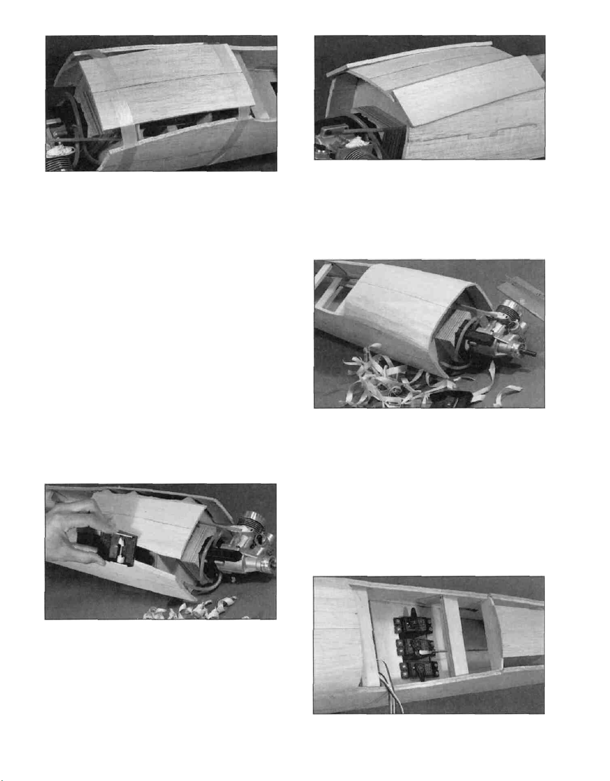
-16-
possible. Make sure you will still be able to install
and work on the servo linkages. These servo
positions are not critical, but will help you balance
the plane without using extra weight. The die-cut
1/8" ply servo tray (SKY6W10) is designed to fit in
the doubler lightening hole for most installations,
but will have to be cut down in width to fit towards
the rear of the plane. It can be glued just below
the lightening hole when it needs to be installed
farther forward as shown in the photo. Check your
servos to make sure they will fit into the tray and
are not held off the tray by the cockpit bottom.
Securely glue the tray in place.
D 3. Install the fuel tank using four #64 rubber
bands (not included) as shown in the photo.
Determine where the fuel and vent tubes should
pass through the firewall to match up with your
particular engine. Drill a 1/4" hole for each tube to
pass through the firewall. The larger holes will
allow you to seal around the tubes with silicone
bathtub sealer. Install the fuel tubing, but be sure
to leave a couple extra inches for good measure.
Mark on the front of the firewall which tube is fuel
and which is the vent.
D 5. Determine the location where the throttle
pushrod (not included) will pass through F1.
Normally, a solid wire pushrod will work fine for the
throttle pushrod. Drill a 3/16" hole (or whatever
size you need) in the firewall for the throttle
pushrod guide tube. Cut the outer guide tube to
length and roughen the outside of the tube with
medium grit sandpaper. Slide the tube into place
and glue it with thin and then thick CA. Refer to the
plans to get an idea of how to route the pushrod.
D 4. Determine where your servos should be
mounted. If you are using a lighter engine (.61 .75 2-cycle) the servos should go as far forward as
practical. If you are using a heavy engine (1.20
4-cycle) the servos should go as far back as
D 6. Locate the 1/4" x 2-3/4" x 3" ply landing
gear plate (SKY6F30) and test fit it in place
between LG-1 and LG-2. NOTE: The grain
should run from LG-1 to LG-2. Enlarge the slots
if necessary to get the plate to fit. When satisfied
with the fit, securely epoxy the plate in place.
17-
D 7. Cut the 3/16" x 2" x 18" balsa sheet
(SKY6F24) in half and glue the two 9" pieces
together to form a 4" wide bottom nose sheet.
Center the 4" wide sheet over the bottom of the
fuselage nose and glue it to formers F2 and LG1
first. It should extend 1/16" behind F2 and the rest
should extend forward of the firewall. Use a piece
of strapping tape to hold it in place while the glue
cures. Wet the outside surface of the nose bottom
and allow it to soak in for 5 minutes or so to help it
bend easier. Apply a generous bead of thick CA to
the bottom edge of the firewall. Then bend the
sheeting into place and hold it with another strip of
strapping tape. Apply thin CA and then another
bead of thick CA around each former before
removing the tape. This gluing process makes very
strong joints because the thin CA soaks in and
holds the wood together and the thick CA forms
fillets for extra strength.
D 9. Cut the 1/4" x 1-3/4" x 18" balsa bottom
nose corner (SKY6F25) sheet in half to make two
9" long pieces. Glue these pieces in place on each
side of the nose as shown in the photo.
D 10. Use your razor plane and a sanding block to
rough carve the corners to shape. Refer to the
cross sections on the fuselage plan during this
step. Cut the fuselage bottom and the corners off
even with the front edge of the fuse sides and the
wing saddle.
D 8. Remove the strapping tape and use a razor
plane and a sanding block to shape the edges of
the bottom and the fuse sides to match the bevel
of the formers.
INSTALL TAIL PUSHRODS
D 1. Install the elevator, rudder and throttle servos
using the screws that came with the servos. Screw
18-
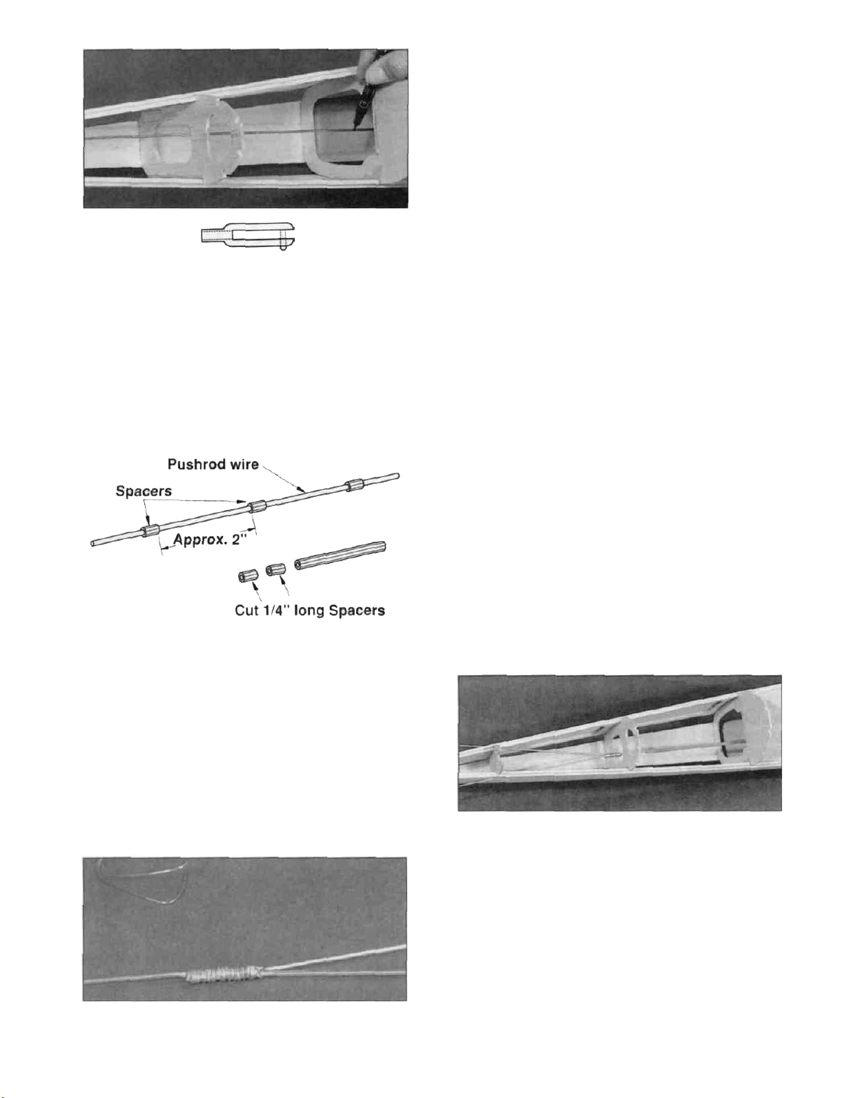
Nylon Clevis
the plan These will make the "Y" part of the
elevator pushrod. Lay the two 12" wires on the
plan so they are lined up with the ones drawn Lay
the forward pushrod wire on top of the two 12"
rods and tack glue the three together with a drop
of CA Wrap the pushrod junction with the silver
wrapping wire (WIREST15) provided in the kit
and securely solder the three pushrod wires
together A good solder joint is necessary here, so
follow the hints given below.
a nylon clevis (NYLON17) about 1/2" onto one of
the 34" threaded wires (WIRES17) Hook up the
clevis to the elevator servo and, with the servo arm
in its neutral position, use a fine tip permanent
marker to accurately mark where the pushrod wire
goes through formers F3 and F4.
D 2 Lay the 34" wire down over the fuselage top
view and line up the marks you made with the F3
and F4 formers on the plan Cut the 34" wire off
where the plans show it ending, to make the
forward part of the elevator pushrod Cut four 1/4"
long yellow pushrod spacers from the 6-1/2" long
inner pushrod piece (PLTB004) Slide these
spacers onto the pushrod wire and position them
near the threaded end until after the soldering
operation.
SOLDERING HINTS
A Roughen the area to be soldered with fine
sandpaper Then thoroughly clean the items to
be soldered with alcohol or degreasing solvent.
B. Apply a small dab of soldering flux.
C Heat the metal with a soldering gun or iron, and
apply the solder to the metal, not the iron The
metal must get hot enough to melt the solder,
and the solder must freely flow into the joint.
D. Do not move the parts until the solder has
cooled
E. Clean off the excess flux with alcohol or solvent
and test the joint for strength.
D 3 Bend two 12" pushrod wires (WIRES16) 1"
from the unthreaded end to the angle shown on
D 4 Cut a piece of pushrod outer tube
(PLTB002) 10" long and scuff the outside of the
tube with sandpaper Slide the 1/4" inner spacers
near the middle of the elevator pushrod wire and
space them about 2" apart Remove the nylon
clevis from the servo end of the elevator pushrod
and slide the 10" long outer tube onto the pushrod.
Install the pushrod in the fuselage by inserting the
servo end through former F4 and sliding it forward
until the "Y" will slip down into the fuselage Then
back the pushrod out the top set of exit slots.
Screw the nylon clevis back onto the servo end of
the pushrod and hook it up the servo arm.
19-
D 5 Cut a scrap piece of balsa to fit about 2" in
front of the pushrod "Y" junction and glue it in
place This will be a pushrod brace and both the
elevator and rudder pushrod outer tubes will be
glued to it Glue the elevator pushrod guide tube to
the top of the brace so the end of the guide tube is
approximately 1-1/2" away from the solder joint
Operate the servo horn by hand to make sure all
the inner spacers stay inside the guide tube
throughout the elevator operation range Make
another balsa brace to go near the servo end of
the guide tubes and glue it in place.
ASSEMBLE THE CABANES
D 1 Punch out the die-cut 1/8" ply cabane wire
holders (SKY6F13) and glue an "L" side to one of
the center pieces Glue an "R" side to the other
center piece Notice that the "L" (left) sides are 1/8"
longer than the right side. This is to allow for the
engine right thrust.
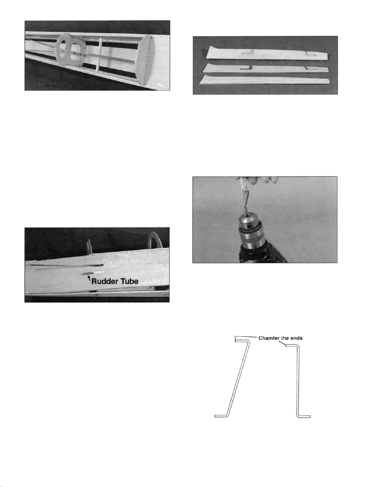
D 6 The rudder pushrod guide tube should be
installed now Cut it to fit from the lower right
pushrod exit to the front pushrod brace Scuff the
outer surface of the tube with sandpaper Allow the
tube to extend past the pushrod exit a few inches
and securely glue it in place After the glue has
cured, cut the tube off flush with the fuselage side.
Use HobbyLite filler to fill around the rudder pushrod
cut-out You can also fill the other rudder cut-out on
the left fuselage side When the filler is dry, sand it
and the pushrod flush with the fuse side.
D 7 If you would like to install an extra pushrod
tube in which to route the receiver antenna, now is
a good time to do it Just drill holes where
necessary and securely glue it in place.
D 2.Use a hobby knife to chamfer the front end of
each 5/32" OD x 3/4" brass tube (BRST021) If
you have a hand drill with a relatively slow speed,
you can chuck the tube in the drill to do this Vary
the angle of the knife blade during this process to
obtain a nice rounded chamfer.
D 3 Locate the 1/8" front and rear left side
cabane wires (WBNT177 and WBNT179) These
are going to slide into the 5/32" OD brass tubes so
their ends need to be smoothly chamfered Use
some very fine (600 grit) sandpaper to smooth out
-20
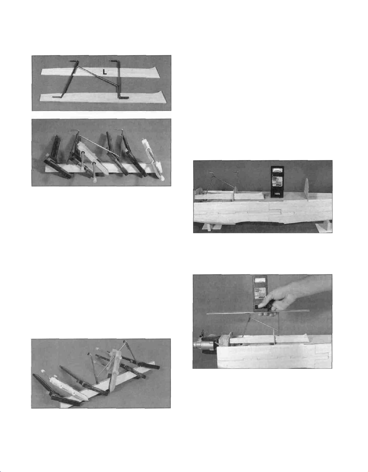
the front of each wire so it will easily slide into the
tube. Test fit the tubes onto the wires.
D 4. Test fit the two left side cabane wires and a
1/8" middle cabane wire (WBNT178) in place in
the die-cut grooves of the Left holder to make sure
they fit correctly. Remove the wires, scuff up the
lower ends with sandpaper and clean them with
alcohol to remove any oils. Spread epoxy in the
grooves and replace the wires. Add more epoxy on
top of the wires and on the center holder. Install
the other "L" side and tightly clamp the assembly
together until the epoxy cures. Make sure the wires
stay properly oriented while the glue is curing. Do
not worry about the bends being perfect. We will
"tweak" them later. You may also notice that the
wires are slightly thicker than the wood. This is due
to manufacturing tolerances in the wood. If this is
the case, just make sure you use enough epoxy to
fill the gaps. Wipe any excess epoxy off the
assembly with a paper towel and alcohol.
assembly to the same length as the sides. Do not
sand into the wood on the bottom of the
assemblies, though, as they are designed to
automatically set the top wing incidence.
SETTING THE TOP WING
INCIDENCE
D 1. You need to check the top wing incidence
before gluing the cabane holders in place. To do
this, temporarily install the left cabane strut. You
will need an incidence meter or a level.
D 2. Block the fuselage up until the cockpit sides
are level.
D 5. Build the right side cabane assembly
using the same procedure outlined above. When
both the right and left cabane assemblies are
cured, carefully sand the edges to remove any
excess glue. Sand the center piece of the right
D 3. With the cabane holder fully seated in its
notches, check to make sure the horizontal parts of
the cabane wires are directly over the center of the
fuselage. If necessary, tack glue the holder in
place and carefully put a level or incidence meter
across the cabane wires. The top wing should
have 1 degree of NEGATIVE incidence (front wire
1/16" lower). Adjust the position of the holder in its
slots, if necessary, until the incidence is correct.
You can do this by cutting the notch in F1B lower
-21
-
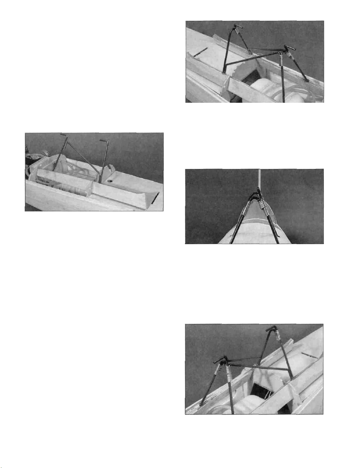
to allow the front end of the holders to drop. If you
have to raise the aft end of the holders off the
cockpit bottom to set the incidence, you should
glue scrap wood in the space between the holder
and the cockpit bottom. When you have it correctly
positioned, make a mark on the formers and the
holder so it can be accurately replaced. Normally,
the incidence will be correct when the holder is
bottomed out in both the notches. If it does not
seem to be correct, start over and re-check
everything before continuing. NOTE: When
using a level, the incidence is correct if you put a
scrap of 1/16" balsa between the level and the
front cabane wire and the level is level.
A. Wrap the front right joint first.
B. Wrap the front left joint second. The right wire
goes on the right side of the left front wire, and the
left middle wire goes behind the left front wire.
C. Wrap the rear wires together.
D 4. Epoxy the left cabane holder in place,
making sure any marks you made are lined up. Be
sure to glue the holder to both the formers and the
cockpit bottom.
D 5. Test fit the right holder in place and insert the
die-cut 1/8" ply instrument panel (SKY6F11) in its
slot to make sure it will fit. If the aft end of the
cabane holders get in the way, sand them until the
panel will fit. Also check the bends of the right
front and right rear cabane wires to make sure
they will be tangent to the left wires. If not, bend
them with pliers until they are.
D 6. Epoxy the right cabane holder in place. Don't
worry if the wires don't match up perfectly, as they
will be joined later. Be sure to glue the holder to
both formers and the cockpit bottom. Scrape any
excess epoxy off of the cabane wires.
SOLDERING THE CABANE WIRES
TOGETHER
D. Temporarily slide the fin into place on the
fuselage. Sight down the two horizontal wires
and check to make sure they are in line with
each other and the fin. If not, adjust the
wrappings or bend the wires if necessary to get
them straight (wrap the wire with a cloth first to
prevent scratching).
D 1. First, clean all the wires with alcohol to
remove any oil. Attach the wires to each other in
the following order by wrapping the joint with the
silver wire provided and soldering the joint with
acid core solder. NOTE: It is easier to get a good
looking solder joint if the wire is wrapped tightly
and uniformly around the wire.
D 2. Solder all three joints together. You will need
at least a 250 watt soldering iron or preferably a
propane torch. Make sure you get good solder flow
on all three joints.
-22-
 Loading...