


GPMA0214
Super Sportster
90/120
Instruction Book
READ THROUGH THIS INSTRUCTION
BOOK FIRST. IT CONTAINS IMPORTANT IN.
STRUCTIONS AND WARNINGS CONCERNING THE BUILDING AND USE OF THIS
MODEL.
INSTRUCTIONS IN BOXES LIKE THIS
ARE VERY IMPORTANT AND SHOULD BE
FOLLOWED CAREFULLY.
WARNING!
This R/C kit and the model you will build is not a toy'. It is capable of serious
bodily harm and property damage. IT IS YOUR RESPONSIBILITY AND YOURS
ALONE — to build this kit correctly, properly install all R/C components and flying
gear (engine, tank, pushrods, etc.) and to test the model and fly it only with experienced, competent help in accordance with all safety standards and common
sense as set down in the Academy of Model Aeronautics Safety Code. It is suggested that you join the AMA and become properly insured before you attempt to
fly this model. IF YOU ARE JUST STARTING R/C MODELING, CONSULT YOUR
LOCAL HOBBY SHOP OR WRITE TO THE ACADEMY OF MODEL AERONAUTICS
TO FIND AN EXPERIENCED INSTRUCTOR IN YOUR AREA.
Academy of Model Aeronautics
1810 Samuel Morse Dr.
Reston, VA 22090
(703) 435-0750
PO BOX 721 URBANA ILLINOIS 61801

TABLE OF CONTENTS
INTRODUCTION ..................... 2
PRECAUTIONS ...................... 3
ENGINE AND MOUNT SELECTION .... 3
LANDING GEAR CONFIGURATION .... 3
CHOOSING YOUR RADIO AND SERVOS . 3
OTHER ITEMS REQUIRED ............ 4
SUPPLIES AND TOOLS NEEDED ...... 4
HARDWARE ......................... 5
TYPES OF WOOD .................... 5
GET READY TO BUILD ............... 6
TAIL
FEATHERS
BUILD THE RUDDER ................. 6
BUILD THE FIN ..................... 8
BUILD THE ELEVATORS ............. 8
BUILD THE STABILIZER .............. 8
INSTALL THE HINGES ............... 8
WING
...................................
BUILD THE WING PANELS ........... 9
JOIN THE WING PANELS ............ 12
COMPLETING THE WING ............ 13
AILERON TORQUE RODS ............ 14
FIBERGLASS THE CENTER SECTION . 15
INSTALL AILERONS ................ 15
INSTALL WING DOWELS ............ 16
LOWER FUSELAGE ASSEMBLY ......... 16
INSTALL NOSEGEAR BEARING
INSTALL REAR PUSHROD GUIDE
TUBES ............................. 20
INSTALL CHIN BLOCK AND BOTTOM
SHEETING ......................... 21
MOUNT THE WING TO THE FUSE .... 21
MOUNT THE ENGINE ............... 22
INSTALL NOSE GEAR ............... 23
INSTALL FRONT PUSHROD GUIDE
TUBES ............................ 24
INSTALL FUEL TANK ............... 24
UPPER
FUSELAGE STRUCTURE
FORMERS, STRINGERS AND HOOD ... 24
INSTALL COCKPIT FLOOR ........... 25
INSTALL HOOD SHEETING .......... 26
INSTALL REAR STRINGERS ......... 26
...................
......
........
6
9
18
24
COMPLETING THE FUSE AND WING .... 26
CONSTRUCT THE NOSE ............. 26
SAND THE FUSELAGE .............. 28
INSTALL WING FAIRINGS ........... 29
MOUNT THE STABILIZER AND FIN . . 30
LOCK STABILIZER TO FUSELAGE .... 31
FINISH MOUNTING THE STAB
AND FIN .......................... 32
SERVOS, HORNS AND
MOUNT AILERON SERVO AND
PUSHRODS ......................... 33
INSTALL SERVOS ................... 33
INSTALL ELEVATOR AND RUDDER
HORNS ............................ 33
INSTALL PUSHRODS ................ 34
CANOPY AND WHEEL
PREPARE THE CANOPY ............. 34
WHEEL PANTS ..................... 34
FINISHING
PRE.FLIGHT ........................... 39
PARTS
PREVENTING CONTROL SURFACE
.............................
ADDITIONAL FUELPROOFING ....... 36
BALANCE THE AIRPLANE
LATERALLY ........................ 36
FINAL SANDING .................... 36
COVERING ......................... 36
GLUE THE HINGES ................. 37
INSTALL PILOT ..................... 37
GLUE CANOPY IN PLACE ........... 37
WING SEATING TAPE ............... 38
RE-INSTALL ENGINE & RADIO ...... 38
BALANCE YOUR MODEL ............ 38
FINAL HOOKUPS AND CHECKS ..... 38
CHARGE THE BATTERIES ........... 39
FIND A SAFE PLACE TO FLY ........ 39
GROUND CHECK THE MODEL ....... 39
RANGE CHECK YOUR RADIO ........ 39
ENGINE SAFETY PRECAUTIONS ..... 39
AMA SAFETY CODE ................ 39
FLYING ............................ 40
LIST
............................
FLUTTER
.........................
PUSHRODS
PANTS
...........
......
32
34
36
41
43
INTRODUCTION
Pssst! Please don't tell your Super Sportster
90/120 how big it really is, because it thinks it is a
"40-size"! What we mean is that this fantastic
airplane flies with all the smoothness and agility of
our other Super Sportsters (20, 40 and 60), and we
can hardly tell the difference, except for the awe-
some size and power! We think you'll agree that
this is the most exciting Super Sportster yet!
Yes, the Super Sportster 90/120 is a scaled-up
version of our Super Sportster 60, but we have incorporated many major structural improvements to add
strength (without extra weight) and to make it much
easier to build straight and true.
In this book we'll take you, one easy step at a
time, through the construction sequence, plus we'll
give you specific pointers on installing your radio,
engine and accessories, and end up with tips on
finishing, balancing and flying your Super Sportster
90/120.
Before starting to build, we encourage you
to read through these introductory pages very
thoroughly, as they contain a lot of vital information
you need to know, such as decisions you must make
now, engine and radio selection, safety precautions
and additional items you will have to purchase.
This is not a beginner's airplane! While the
Super Sportster 90/120 is easy to build and flies
great, we must discourage you from selecting this
kit as your first R/C airplane. It is fast, highly maneuverable, and lacks the self-recovery characteristics
of a good basic trainer such as the Great Planes
PT Series airplanes. On the other hand, if you have
2

already learned the basics of R/C flying and you are
able to safely handle an "aileron trainer" airplane
such as the Great Planes Trainer Series or Big Stik
Series airplanes, the Super Sportster 90/120 is an
excellent choice
We think you will agree that the Great Planes
Super Sportster 90/120 is the highest quality, best
building and best flying airplane of its type on the
market today!
*********!]<S|!*#*****;i!il!***S|!*S|S***!tl*#****S|S!|!!|!**!|!*
DECISIONS YOU MUST MAKE
NOW
ENGINE AND MOUNT SELECTION:
The recommended engine size range is as fol-
lows:
If you have any questions or problems about
building or flying this airplane, or if any of the kit
parts are badly warped, defective or missing, please
call us at (217) 367-2069 between 8 00 AM and 4 00
PM (central time) and we'll be glad to help If your
call concerns defective or missing parts, please be
ready to give us the 8-digit code (on the box end flap)
and the part numbers
PRECAUTIONS
1 You must build the plane according to the
plans and instructions Do not alter or modify the
model as represented by the plans, as doing so may
result in an unsafe or unflyable model In a few cases
the plans and instructions may differ slightly from
the photos In those instances you should assume the
plans and written instructions are correct
2. You must take time to build straight, true
and strong
3. You must use a proper R/C radio that is in
first class condition, the correct sized engine and
correct components (fuel tank, wheels, etc.)
throughout your building process
4 You must properly install all R/C and other
components so that the model operates properly on
the ground and in the air.
5 You must test the operation of the model
before the first and each successive flight to insure
that all equipment is operating and you must make
certain that the model has remained structurally
sound Be sure to check the nylon clevises often, and
replace if they show signs of wear.
6. You must fly the model only with the com-
petent help of a well experienced R/C pilot if you
are not already an experienced and knowledgeable
R/C pilot at this time.
Note. We, as the kit manufacturer, can provide
you with a top quality kit and great instructions,
but ultimately the quality and flyability of your
finished model depends on how you build it, therefore, we cannot in any way guarantee the performance of your completed model, and no representations
are expressed or implied as to the performance or
safety of your completed model
.61 - .91 cubic inch displacement 2-cycle
.90 - 1.20 cubic inch displacement 4-cycle
Do not power your airplane with an engine
larger than the recommended size ( 91 2-Cycle, 1 20
4-Cycle) Also, if using a 91 2-Cycle, do not use a
tuned pipe
When you start building the fuselage, one of
the first steps will be to cut off a portion of the front
of the fuselage sides and fuselage doublers if you will
be using a 4-cycle engine, due to the increased length
and weight of the 4-cycle engines Therefore, it is
important that you have your engine close at hand
while building.
This kit includes hardwood engine mounting
rails, but you may wish to purchase a custom engine
mount for your engine, and the instructions allow
for that type of installation.
LANDING GEAR CONFIGURATION
The Super Sportster 90/120 may be built with
a "taildragger" or "tricycle" landing gear configuration Some people prefer the tricycle gear setup because they believe it handles better on the ground
Others prefer to build it as a taildragger for the
classic appearance This airplane actually handles
very well in either configuration, so the choice is up
to you Please make this decision now, as it will
affect several things you will do during the construction.
CHOOSING YOUR RADIO AND SERVOS
Most good quality radio systems on the market
today are suitable for this airplane You may, however, have to purchase a 5th servo or a high-torque
servo (see the note below).
IMPORTANT NOTE We have found standard servos which provide approximately 45 oz/in of torque
to be satisfactory for use in the Sportster 90/120 with
the following exception If you are using standard servos you should use one servo for each
elevator (use a "Y"- Connector to plug both elevator
servos into the elevator channel of your receiver) If
you want to use only one servo for the elevators, you
must use two pushrods and a high torque servo providing at least 60 oz/in of torque.
Remember: Take your time and follow directions to end up with a well-built model that
is straight and true
Please make sure you select a radio system
that is on a frequency designated "for aircraft use
only", and one that meets current FCC standards.

OTHER ITEMS REQUIRED
Propellers (see engine instructions for size)
3" diameter Spinner
Fuel Tank (14 - 16 oz. or larger)
(Larger tanks require custom fitting)
2 - 3" diameter Main Wheels
1 - 2-3/4" diameter Nose Wheel
(or)
1 - 1-1/4" diameter Tail Wheel
4 - 3/16" Wheel Collars for Main Wheels
2 - 5/32" Wheel Collars for Nose Wheel
(or)
2 - 3/32" Wheel Collars for Tail Wheel
Iron-on Covering Material
Silicone Fuel Tubing
Foam Wing Seating Tape
Foam Rubber Padding, 1/2" thick
Dummy Pilot Figure (2-1/2" - 3" tall)
2 - DuBro E-Z Connectors (or similar)
"Y"-Connector (for double elevator servos)
SUPPLIES AND TOOLS NEEDED
2-3 oz. - Thin CA Adhesive Pliers
2 oz. - Medium or Thick CA Adhesive Screw Driver
2.5 oz.- 5 Minute Epoxy T-Pins
2.5 oz.- 30 Minute Epoxy Straightedge
Hand or Electric Drill Masking Tape
Drill Bits (No. 53. 1/16", 5/64", 3/32" 7/64", Sandpaper, (Coarse, medium and fine grit)
1/8", 5/32", 3/16", 11/64", 13/64", 1/4", 5/16" T-Bar sanding block, or similar
Sealing Iron Waxed Paper
Heat Gun Balsa Filler
Hinge Slotting Tool 1/4-20 Tap
Hobby Saw (X-Acto Razor Saw) Tap Wrench
X-Acto Knife, #11 Blades Dremel Moto Tool or similar (Optional)
******************************************************
COMMON ABBREVIATIONS USED IN THIS
BOOK AND ON THE PLANS:
Stab = Stabilizer
Rt = Right
Elev = Elevator
LE = Leading Edge (front)
TE = Trailing Edge (rear)
Lt = Left
" = Inches
Fuse = Fuselage
LG = Landing Gear
Ply = Plywood
4
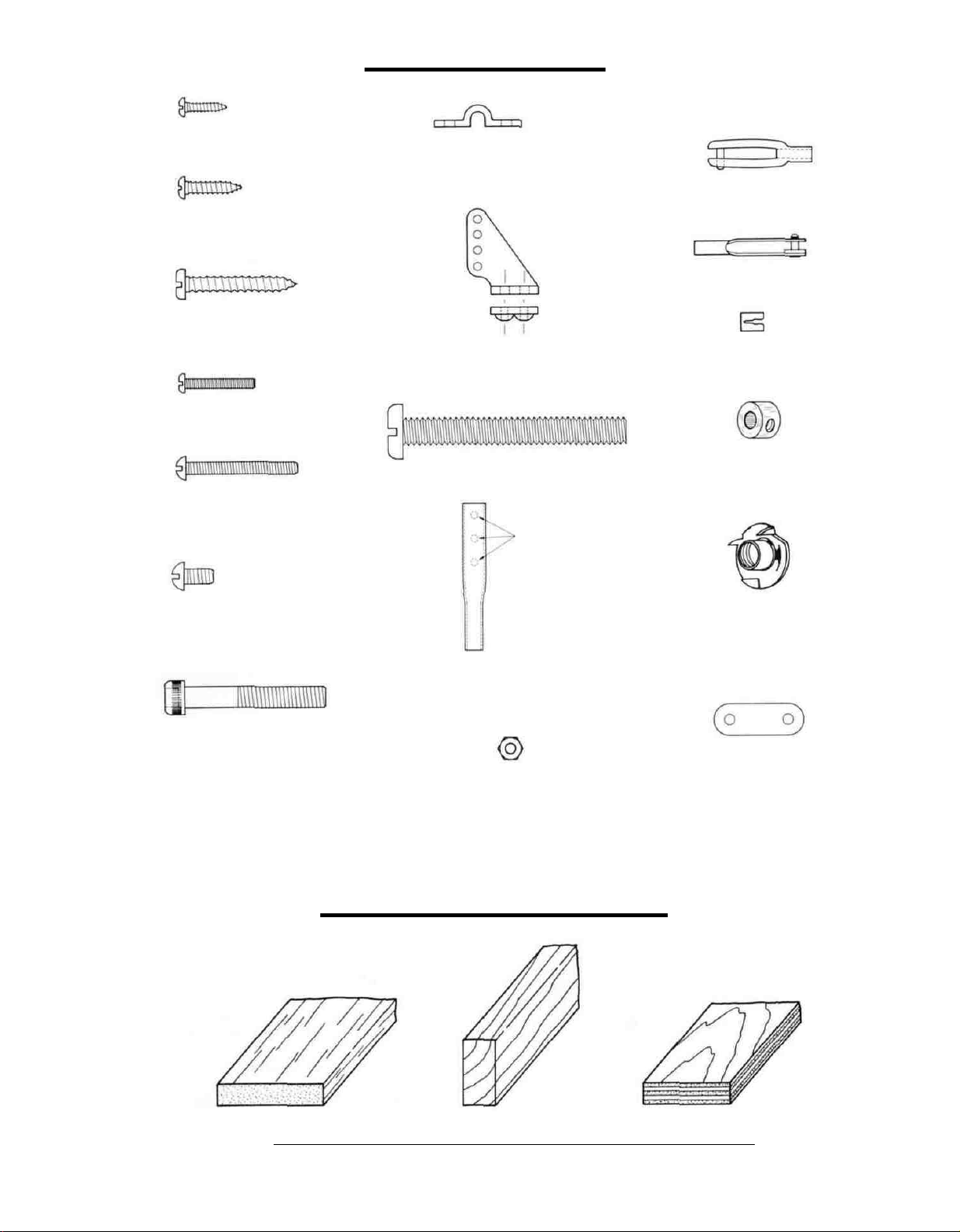
HARDWARE
#2x3/8"
#4x1/2"
2-56 x 5/8" SCREW
SCREW
SCREW
#6 x I SCREW
4-40x1" BOLT
LANDING GEAR CLIP
(NYLON)
NYLON HORN AND NUT PLATE
1/4-20
NYLON
•TO
BOLT
HOLES
BE
DRILLED
NYLON CLEVIS
METAL CLEVIS
RETAINER CUP
5/32" COLLAR
6-32 x 1/4 " SCREW
10-32 SOCKET HEAD
CAP SCREW
BRASS AILERON HORN
2-56
HEX
NUT
TYPES OF WOOD
NYLON L.G. STRAP
BALSA HARDWOOD PLYWOOD
5
GET READY TO BUILD
D 1. Unroll the plan sheets. Re-roll them inside
out to make them lie flat.
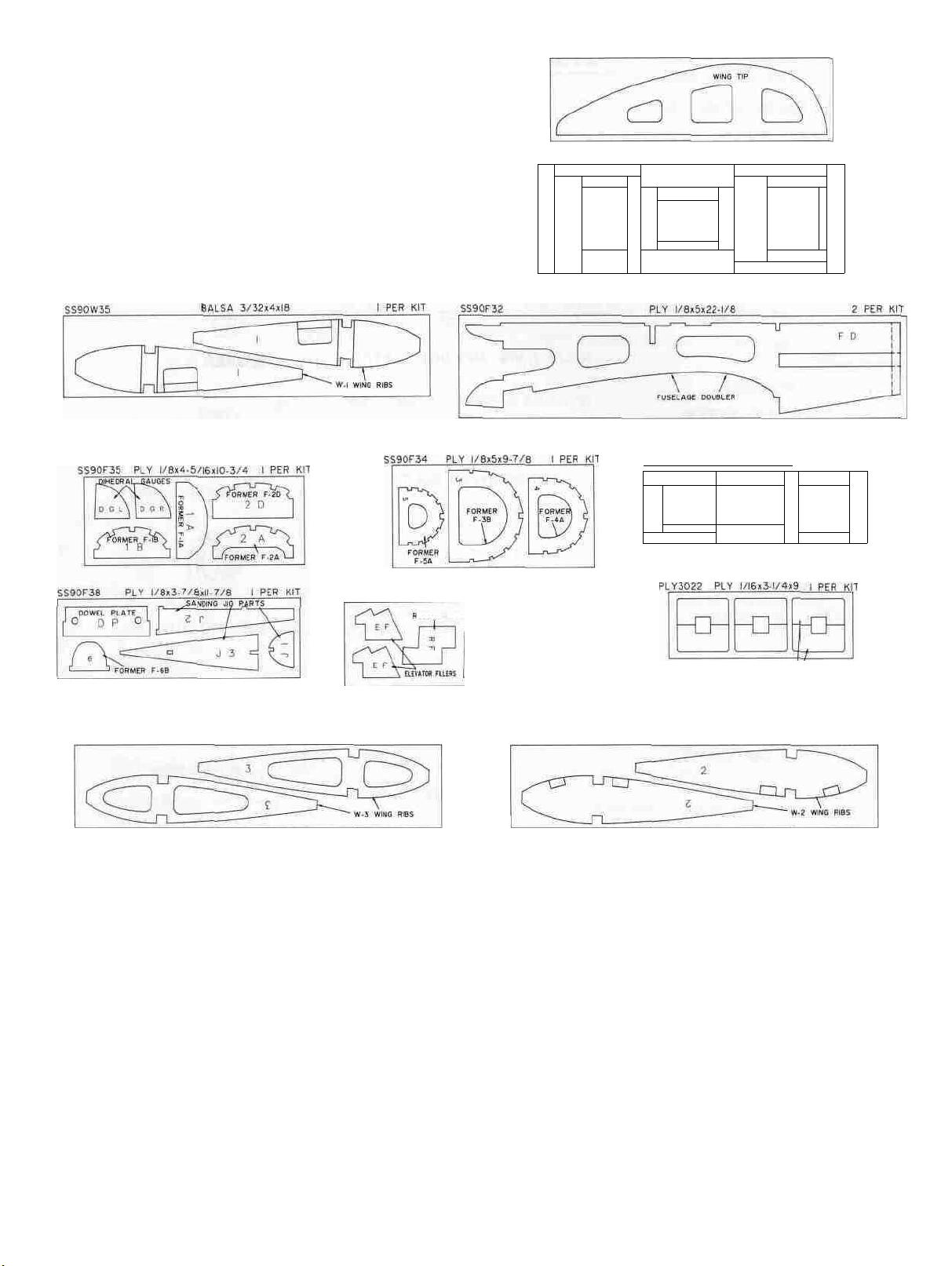
SS90W07 PLY 1/8x4x13-7/8 2 PER KIT
D 2 Remove all parts from the box Figure out
the name of each part by comparing it with
the plans Using a felt tip pen, write the part
name on each piece to avoid confusion later.
Use the die cut patterns shown below to iden-
tify the die cut parts and mark before punch-
ing them out. Save all scraps.
SS90F33 PLY 1/8x4 3/16x12-1/4 2 PER KIT
•UDDER FILLER mil REWIMG H.m\
SS90F37 PLY 1/8x4-7/8x14 PER KIT
A
B
-n
FORMER
Lrf
1
/-
ALIGNMENT
^ BASE
1
SS90F39 PLY l/8x4»10-7/8 I PER KIT
FORMER
/F-5
w
-n
N3
^D
FORMER
FORMER
F2
/
FORMER
F
4
+>
SS90W33
BALSA 3/32x4x18
TAIL FEATHERS
NOTE The Rudder, Fin, Elevators and Stabilizer
are all built in a very similar manner The following
section explains in detail how to build the Rudder
to make you familiar with the procedure, then you
can use the same techniques for building the other
"tail feathers" with very little instruction, except for
a few important comments Here we go!
8
PER
KIT
D B DIHEDRAL BRACE
SS90W34
BUILD THE RUDDER
To build the rudder you'll need the following:
LANDING GEAR DOUBLERS
3
PER
BALSA 3/32x4x18
KIT
1/4" x 3/4" x 36" balsa sticks (set aside the
straightest hard stick for the stabilizer TE)
1/8" x 1/4" x 36" balsa sticks (set aside the two
softest sticks to be used later on the wing tips)
1/16" x 3" x 36" balsa sheets
Two 1/8" die-cut ply rudder filler (RF) pieces
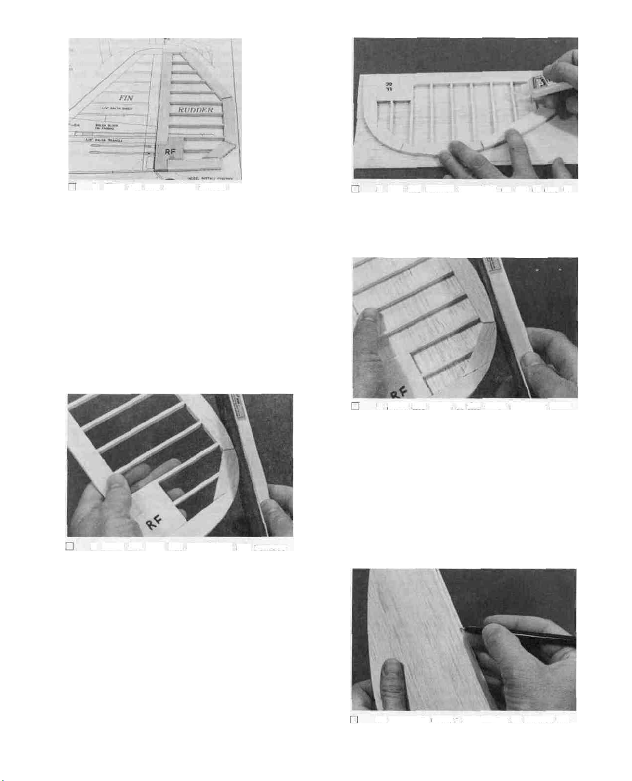
D 1. Tape the fuselage plan down to your flat
work surface Tape a piece of waxed paper over
the fin and rudder portion of the plan.
2. Glue the two rudder fillers (RF) together
using thick CA glue, making one piece 1/4"
thick.
3. Using a razor saw, cut pieces of 1/4" x 3/4"
balsa (from the 36" sticks) to make the rudder
framework. Working right on the plan, glue
these pieces together along with the ply RF
piece, using thin CA glue.
4. From the 1/8" x 1/4" x 36" sticks, cut "ribs"
to fit between the rudder framework, and glue
them in place. NOTE: It is not necessary to
get these ribs in the exact position shown on
the plan.
8. Lay the rudder assembly on top of one of
your 6" x 12" sheets. Hold the rudder assembly
down and apply thin CA glue along the edges
of the framework and ribs.
9. Sand the edges of the 1/16" sheeting flush
with the edges of the framework.
D 10. Apply thick (slow setting) CA glue (or 30-
minute epoxy if you need more time) to the
rudder framework and ribs, then lay the other
6" x 12" balsa sheet in place. Hold the sheeting
in place with your hands or with books until
the glue has set.
5. After the glue has completely set, remove
the rudder assembly from the plan and using
a T-bar sander or a sanding block with coarse
grit sandpaper, sand the outside edge of the
rudder to the approximate shape as shown on
the plan.
6. Examine the rudder framework and add
thick CA glue to any open joints, then use your
T- bar with medium grit sandpaper to sand
both sides of the rudder framework smooth.
7. From the 1/16" x 3" x 36" balsa sheets, cut
four pieces 12" long. Edge glue these pieces
together in pairs, using thin CA glue, to make
two sheets 6" x 12". Sand the surfaces of these
sheets smooth, using a T-bar with medium to
fine grit sandpaper.
D 11. Sand the edges of the sheeting flush with
the edges of the framework.
12. Carefully draw a centerline all around the
edges of the rudder.
D 1. Tape waxed paper over the separate elevator
drawing on the fuse plan Glue the two EF
pieces together, then in the same manner as
the rudder, build the inner framework. Build
two identical elevators.
D 2. Sand the framework to the shape as shown
on the plan.
D 3. Glue 1/16" balsa sheeting to both sides of
the elevators, with the grain running the long
way.
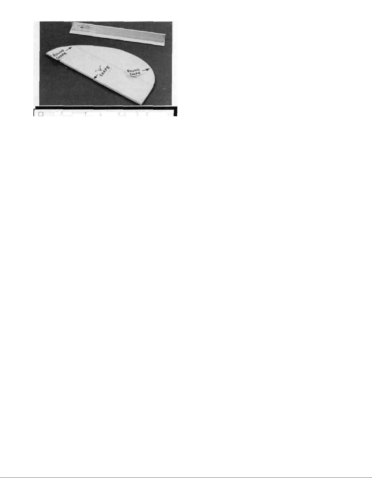
13. Use your T-bar sander to sand the leading
edge of the rudder to a "V" shape (take a look
at the top view of the rudder on the plan to
determine the proper angle of the "V")
D 14 Sand all other edges of the rudder to a
round shape NOTE The centerline you previously drew will help you to sand the same
amount from both sides.
BUILD THE FIN
You'll need the following parts:
1/4" x 2-7/8" x 1-1/2" shaped balsa front fin
filler
1/4" x 3" x 1-1/2" balsa rear fin filler
1/4" x 3/4" balsa sticks
1/8" x 1/4" balsa sticks
1/16" x 3" balsa sheets
D 1. In the same manner as the rudder, build the
inner framework, including the 1/4" fin filler
sheets, the 1/4" x 3/4" sticks and the 1/8" x 1/4"
sticks (for ribs).
D 2. Sand the top front comer to the shape as
shown on the plan.
D 3. Glue 1/16" balsa sheeting to both sides (ver-
tical grain).
D 4. Sand the leading edge (only) to a round
shape.
NOTE: The trailing edge, bottom edge and lower
front edge must not be rounded or V-shaped, instead,
just sand these edges flat.
BUILD THE ELEVATORS
You'll need the following parts:
4 1/8" die-cut ply elevator filler (E F) pieces
1/4" x 3/4" balsa sticks
1/8" x 1/4" balsa sticks
1/16" x 3" balsa sheets
D 4 Sand the leading edge to a "V'-shape, and
the other edges to a round shape.
BUILD THE STABILIZER
You'll need the following parts:
1/4" x 3/4" balsa sticks
1/8" x 1/4" balsa sticks
1/16" x 3" balsa sheets
Shaped 1/4" ply front stab brace
1/4" x 1/2" x 6" ply rear stab brace
1/4" x 3-7/32" x 3" balsa stab center sheet
D 1. Tape waxed paper over the separate
stabilizer'drawing on the fuse plan In the same
manner as the rudder, build the inner
framework, including the front stab brace, rear
stab brace, 1/4" balsa center sheet, 1/4" x 3/4"
sticks and 1/8" x 1/4" sticks.
D 2. Sand the outside edges to the shape as shown
on the plan.
D 3. Glue 1/16" balsa sheeting to both sides, with
the grain running the long way.
D 4. Sand the leading edge and the ends to a
round shape.
NOTE- The trailing edge must not be rounded or
V-shaped. Instead, just sand this edge flat
INSTALL THE HINGES (Do Not Glue)
NOTE: The large one-piece molded hinges supplied
in this kit are strong, easy to install, and provide a
good dampening effect to help prevent dangerous
control surface flutter We recommend that you use
these hinges in your Super Sportster 90/120.
D 1 Lay the rudder and elevators on the plan
and mark the hinge locations Place the rudder
against the fin TE (trailing edge) and transfer
the marks over to the fin. Place the elevators
against the stab TE and transfer the marks
over to the stab.

D 2. Cut the hinge slots on the accurate center-
lines which you previously drew, using a
standard slotting fork and slotting hook. Because the hinges are wider than normal, you
should use the following procedure: When first
inserting the slotting fork, push it in only part-
way along one side of the hinge location, then
push it in the full depth along the other side
of the hinge location, finally, go back and complete the push in the original position. Clean
out the slot with the slotting hook.
D 3. IMPORTANT! Condition or "break-in" the
hinges by folding them tightly back and forth
several times.
D 4. Insert the hinges into the slots and trial fit
the rudder and elevators in place on the fin
and stab. Do not glue the hinges until after
you have covered the model.
WING
BUILD THE WING PANELS
Lt. Rt.
D D 5. Glue two W-3 ribs together to make one tip
rib.
D D 6. Draw an accurate centerline along the rear
edge of the notched balsa trailing edges.
D 1. Tape the wing plan to your flat building
surface, and tape a sheet of waxed paper over
the wing panel portion of the plan.
Q 2. Punch out all the wing ribs from the die-cut
sheets. Compare the ribs with the wing rib patterns on the wing plan and arrange them into
stacks of the same kind of ribs.
D 3. Note that the drawing of rib W-2 shows the
two alternate locations for the main landing
gear blocks. Note also that the W-2 ribs have
partial cutouts for each of the two locations.
If you are building your plane as a taildragger,
cut out the front notches in the W-2 ribs. If
you are building your plane with a tricycle
gear, cut out the rear notches. Trim the die-cut
1/16" ply doublers, and glue them to the W-2
ribs as shown on the plan.
D 4. The notched balsa leading and trailing edges
are supplied in one shaped piece and are held
together by thin strips of balsa. Break these
apart now, and break off any remaining pieces
of the thin balsa. Sand the edges straight with
your T-Bar sanding block.
NOTE: Follow steps 5 through 28 to build the
RIGHT wing panel, then repeat these steps to
build the LEFT wing panel UPSIDE DOWN.
D D 7. Pin one of the notched balsa trailing edges
to the 1/4" x 1-5/32" x 33" balsa jig stick as
shown in the following sketch. Note that the
top of the jig stick must be on the centerline
which you have drawn on the trailing edge.
Notched Balsa
Trailing Edge
Table
Top
T-Pin
_Balsa
Jig Slick
D D 8. Place one of the 3/8" x 1/2" basswood main
spars on the wing plan, line up the right end
with the outside edge of the tip rib and pin the
spar down with crossed T-pins as shown in the
following sketch. NOTE: If you prefer not to
use pins, you may hold the spar firmly in place
using "shot bags" as shown in the photos, which
are made by partially filling a sock with lead
shot.
T-PINS
SPAR
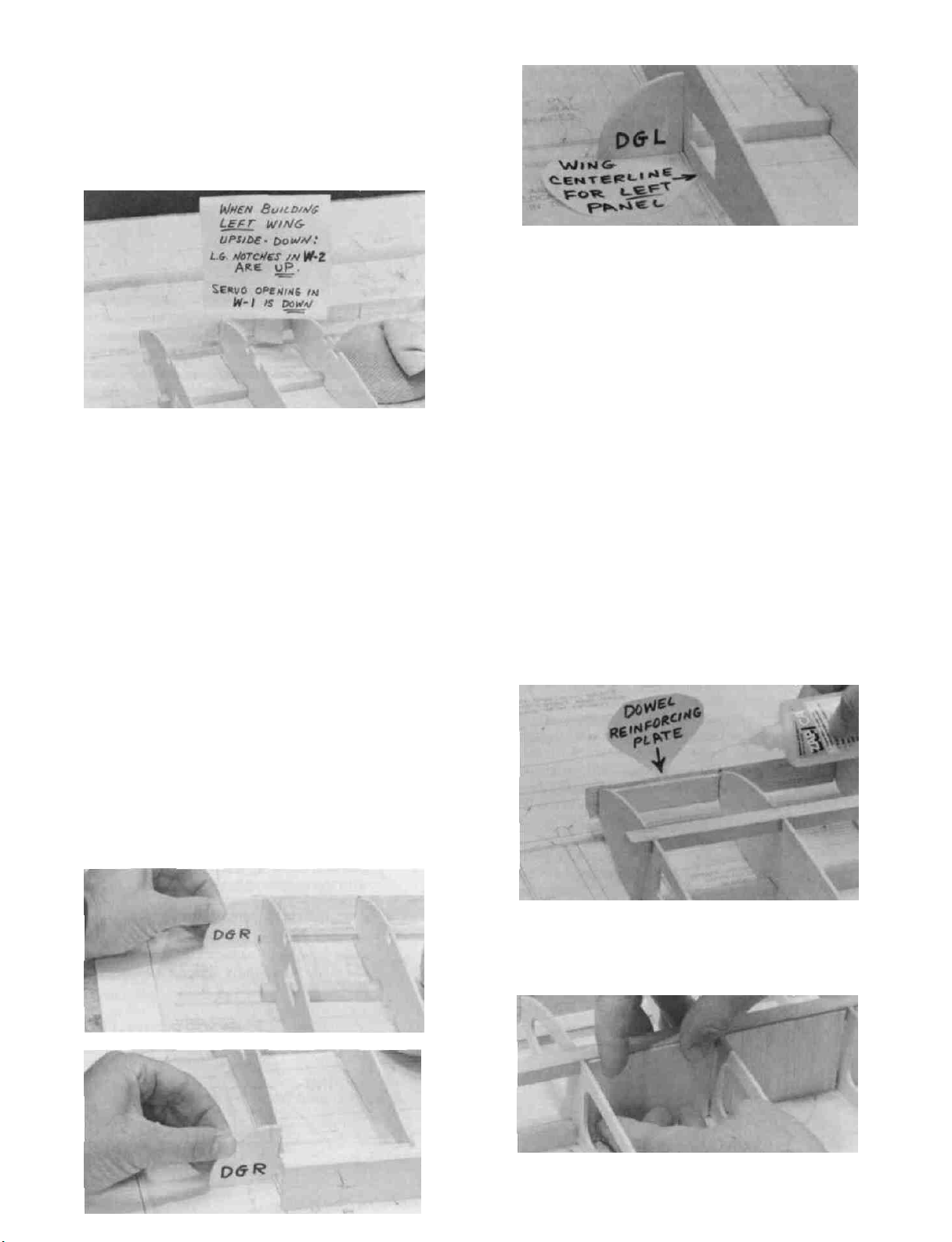
IMPORTANT NOTE!!!!!!!!!!!!!!!!!!
When building the right wing panel, position
the ribs so the landing gear block notches in the W-2
ribs are down, and the servo opening in rib W-1 is
up.
When building the left wing panel, position
the ribs so the landing gear block notches in the W-2
ribs are up, and the servo opening in rib W-1 is
down.
Note that the leading and trailing edges do not have
a notch for the W-1 rib. Use the 1/8" die-cut ply
dihedral gauges "DGR" and "DGL" to position rib
W-1 at the proper angle. When building the right
wing panel, use dihedral gauge DGR to position W-1,
setting the rib's location and tilt with the point of
DGR on the "Right Wing Panel Centerline". When
building the left wing panel (upside down), use dihedral gauge DGL to position W-1, with the point
of DGL on the "Left Wing Panel Centerline".
***********************************************************************
D D 11. Insert the top spar into the notches in the
top of the ribs, with the right end even with
the outside edge of the tip rib.
DO NOT BUILD TWO RIGHT WING
HALVES!!!!!!!!!!!!!!
D D 9. Place the ribs on the spar in their approxi-
mate positions, but do not glue.
D D 10. Hold the notched balsa trailing edge in
place (with jig attached) and carefully work
the ribs into the notches, centering each rib up
and down. In the same manner, insert the ribs
into the notches in the balsa leading edge. Note
that one end of the leading and trailing
edge stock has a notch at the end, and this
notch must be at the wing tip. Do not glue
anything yet.
***********************************************************
PLEASE STUDY THE FOLLOWING NOTE
AND THE ACCOMPANYING PHOTOS
BEFORE PROCEEDING!
D D 12. Make sure the tip rib is vertical (90 degrees
to the work surface), that the spars are lined
up with the outside edge of the tip rib, that rib
W-1 is set at the proper angle, and that all
parts are properly aligned. Apply thin CA glue
to all joints (but do not glue the "jig stick" to
the TE!). Then apply thick CA glue to all joints
which are not tight-fitting.
D D 13. Glue the 1/8" ply dowel reinforcing plate
to the back of the leading edge, between W-1
and W-2.
D D 14. Glue the pre-cut 1/16" balsa shear webs
to the rear edge of the spars in all rib bays
except between W-1 and W-2.
10
D D 15. Lightly sand the tops of the ribs to blend
with the notched trailing edge, if necessary;
then position one of the 3/32" x 1-13/32" x 33"
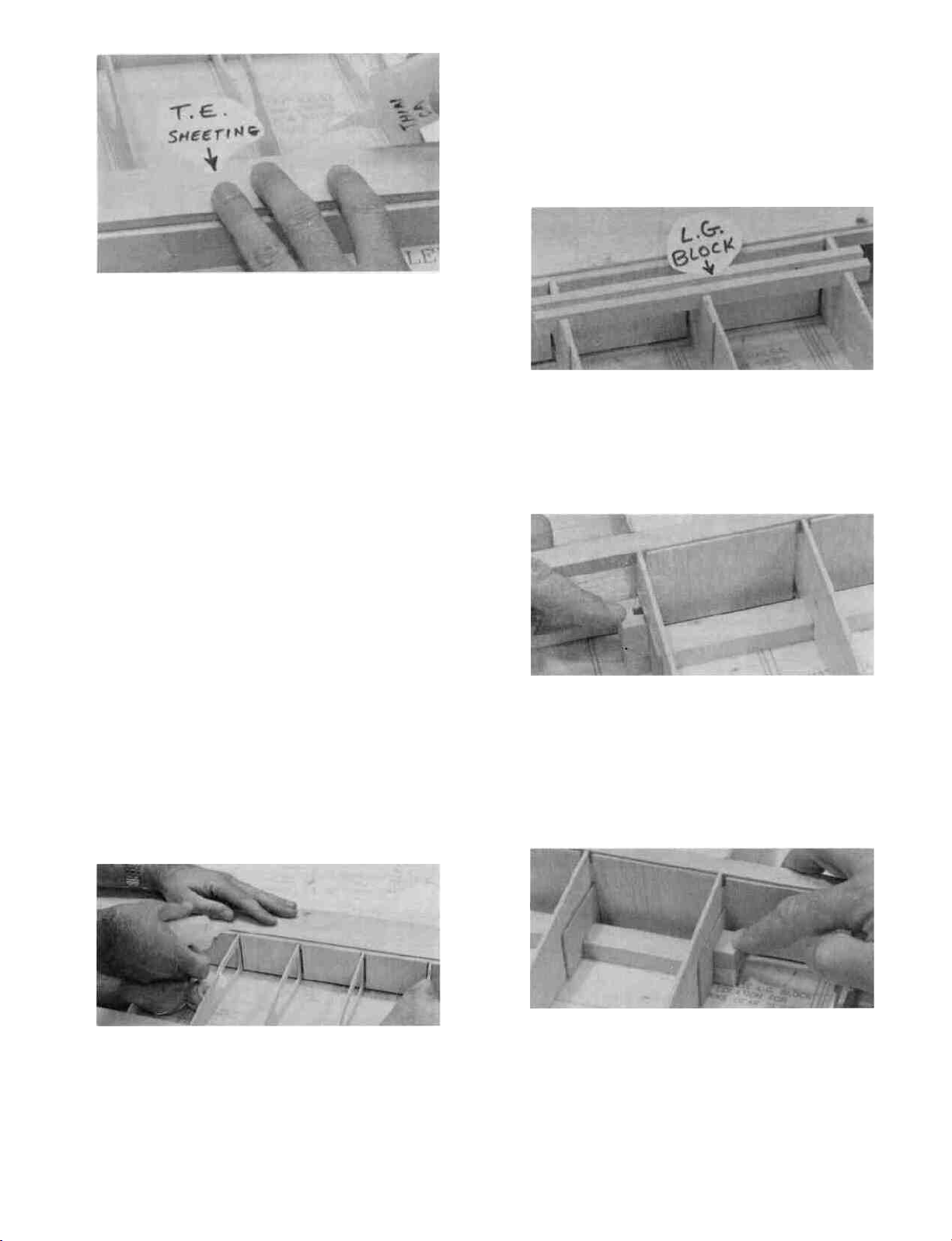
balsa trailing edge sheets so the Rt. end is
even with the outside edge of the tip rib and
glue it in place.
D D 16. If you are building a taildragger, you should
install the grooved hardwood landing gear
block at this time. Refer to steps 20 - 23 for
the correct procedure.
bend the sheeting down onto the ribs and spar.
Hold the sheeting down with masking tape,
pins and your hands until the glue has set.
NOTE: Do not install the TOP leading edge
sheeting until after joining the left and right
wing panels.
D D 20. Trial fit the long grooved hardwood land-
ing gear block into the notches in the W-2
ribs (see the landing gear detail drawing on
the wing plan for proper positioning). File the
notches if necessary for a good fit. Now use
epoxy to securely glue the block in place.
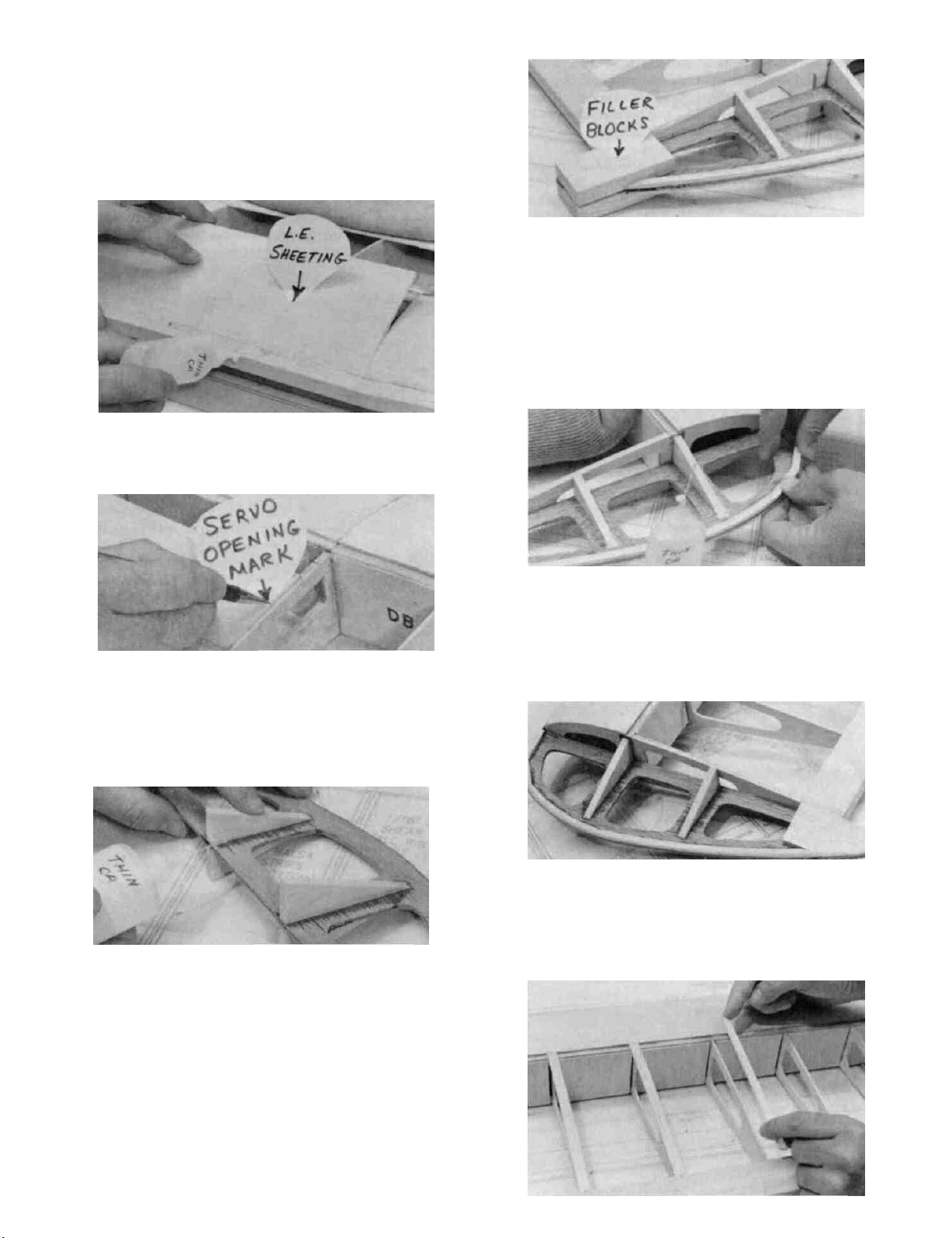
LI D 17. Before applying the leading edge sheeting
in the next step, use your T-bar to lightly sand off
the edges of the shear webs and the rear corners of
the spars to blend with the ribs.
D D 18. Prepare the 3/32" x 3-27/32" x 33" balsa
bottom leading edge sheeting by sanding
one edge to a slight bevel so it will fit snugly
against the back of the leading edge. If you are
building a taildragger, carefully cut out an
opening in the leading edge sheeting for the
landing gear block.
NOTE: It will be helpful to have the following items
handy for the next step . . . thin CA, thick CA, a wet
cloth, masking tape and T-pins.
D D 21. Glue the short grooved hardwood block to
the landing gear block and to the 1/16" ply
doubler as shown on the plan and in the photo,
using 5-minute epoxy. After the glue has firmly
set, insert a 3/16" diameter drill bit down into
the groove in the short hardwood block, then
continue drilling through the long hardwood
block.
D D 19. Position the leading edge sheeting so the
Rt. end is even with the outside edge of the tip
rib. Using thin CA, glue the front (beveled)
edge of the leading edge sheeting to the back
edge of the leading edge. Wet the top surface
of the sheeting so it will bend easier. Apply
thick CA glue to the top edge of the ribs and
to the front half of the spar, then immediately
D D 22. Glue the 1/2" x 3/4" x 1/2" hardwood block
to the other end of the landing gear block and
to the 1/16" ply doubler, using 5-minute epoxy.
D D 23. Trial fit the 3/16" diameter main landing
gear wire into the landing gear block at this
time. Cut or file the groove and hole in the
landing gear block as necessary for a good fit.
11

NOTE: Most standard wheels have a 5/32" diameter
axle hole, so you'll have to drill the hubs of your
wheels to fit the 3/16" diameter landing gear wire
supplied in this kit. Start by using a 3/16" drill bit,
but because the nylon hub material is somewhat flexible, it may be necessary to use a 13/64" drill bit to
get the hole large enough to allow the wheel to turn
freely.
D D 24. Glue the 3/32" balsa trailing edge sheeting
to the other side of the wing in the same manner as described in step 15.
L] D 25. Find the 8 balsa center section sheets
(3/32" x 2-5/8" x 10-1/8") and the 4 balsa center
section sheets (3/32 x 1-3/8 x 10-1/8). Glue 2 of
the 2-5/8 wide sheets and one of the 1-3/8 sheets
to the W-l and W-2 ribs on the bottom of the
wing only Now glue just one 2-5/8 piece of
top center section sheeting in place at the trailing edge (the balance of the top sheeting will
be installed after joining the wing panels).
D D 27. Carefully cut out the center portion of the
W-l ribs (1/8" in front and back of the spars),
to make room for the plywood dihedral braces.
D 28. Now go back and repeat steps 5 through
27 to build the left wing panel. Remember,
you will build the left wing panel UPSIDE
DOWN!
JOIN THE WING PANELS
NOTE: Read Steps 1-5, then make a "dry run"
through these steps before actually proceeding.
1. Lay a piece of waxed paper down at the center
of the wing, place the two wing panels together
at the center, and block up both wing tips 11/2".
D 2. Trial fit the 1/8" ply dihedral braces to
make sure they will readily slide into place.
NOTE: Due to the extremely high stresses which
occur at the center of this wing, you must use
30 minute epoxy in the next step to insure
adequate strength.
D D 26. Using a razor saw, carefully cut off all ex-
cess sheeting, spars, LE and TE even with W-l.
Now sand the ends of the parts you just
trimmed until they are smooth and flush with
the face of W-l. Also sand the outside face of
the tip rib at this time.
D 3. Mix up a batch of 30 minute epoxy and spread
it liberally on the front and back of the spars
between ribs W-l and W-2, on the spar ends,
and on one surface of each of the dihedral
braces. Slide the dihedral braces into place and
immediately proceed to the next step.
D 4. Carefully align the leading and trailing
edges of both wing panels at the centerline and,
while holding them in correct alignment, apply
thin CA glue to the center joint to "lock" the
panels together. Do not apply CA glue to
any area that is already coated with epoxy.
Immediately proceed to the next step.
12
D 5. Clamp the dihedral braces together as shown
in the photo, wipe away any excess epoxy, then
allow the epoxy to fully harden before disturb-
ing the wing.
COMPLETING THE WING
D 1. In the same manner as in Steps 18 and 19
above, glue the top leading edge sheeting in
place.
D 5. Glue the 1/2" x 1-1/2" x 2-15/16" balsa rear
tip fairing blocks in place at the trailing edge
of the wing tips.
D 6. Find the two softest 1/8" x 1/4" x 36" balsa
sticks that you previously set aside when building the rudder.
D 2. Glue the top center section sheeting in
place (Note: As you do so, it will be helpful to
mark the location of the aileron servo opening on the top of the sheeting for future reference).
D 3. From the 1/4" x 1" x 7" balsa sheet and the
1/4" x 7/8" x 5-7/8" balsa sheet, cut out the triangular tip braces using the pattern on the wing
plan, then glue them to the 1/8" ply wing tips.
D 7. Glue 1/8" x 1/4" balsa strips to the top and
bottom of the wing tips as shown in the photos.
Do not be concerned if the sticks break when
they are bent around the curve. Just glue them
down and-sand them to a rounded shape later.
D 8. Use a sanding block with coarse (#60 or
#80) sandpaper to blend the rear tip fairing
blocks to the wing tips, as shown. Also sand
the outside edge of the wing tips to a smooth,
rounded shape.
D 4. Glue the wing tip and tip brace assemblies
to the tip ribs.
13

D 9. From the six 3/32" x 3/8" x 36" balsa sticks,
cut cap strips to fit between the trailing edge
sheeting and leading edge sheeting. Glue these
cap strips to the top and bottom edges of all
exposed ribs as shown on the plan.
D 10. Temporarily install the main landing gear
wires into the wing. Now fill the unused portion
of the slot in the landing gear block with pieces
cut from the 3/16" x 3/16" balsa stick. Glue
these pieces in place.
D 11. Temporarily secure the landing gear in
place with the nylon straps and #2 x 3/8"
screws as shown in the landing gear detail
drawing and the cross-section drawing of W-2
on the wing plan.
AILERON TORQUE RODS
D 6. Drill holes in the flattened portion of the
brass horn for the clevis pin (Note: The proper
size drill bit to use here is a #53 bit, available
at most hardware stores. You may, however,
use a 1/16" bit, but a slight amount of "slop"
may result). After drilling, carefully remove
the sharpness from the edge of the holes with
an Xacto knife.
D 7. Repeat the above process for the other torque
rod. You should now have a right and a left
torque rod.
D 1. Sand the short end of the torque rod with
320 grit sandpaper.
D 2. Roughen the surface of the brass bearing
tube with 100 grit sandpaper.
D 3. Clean the torque rod and bearing tube with
degreasing solvent or thinner.
D 4. Apply a small amount of soldering flux to
the short end of the torque rod, push on the
brass tube which has been flattened at one end
and rotate it to the proper position.
D 5. Heat the brass tube with a soldering gun or
iron while applying solder to the joint. When
the assembly becomes hot enough the solder
will melt and flow freely into the joint. Then
remove the heat and allow to cool without disturbing.
D 8. Find the two grooved, tapered balsa center
trailing edge pieces, and trial fit the torque
rods into them. Determine from the plan where
to cut the clearance notches in the center trailing edges and the wing trailing edge, which
permit the torque rod horns to travel freely.
Note: The torque rod horns must exit the
TOP of the wing!
D 9. Slide the brass torque rod bearings toward
the brass horns, then use a toothpick to apply
a small amount of petroleum jelly to the ends
of the brass tubes. This will help prevent glue
from locking up the torque rods.
D 10. Use 5-minute epoxy to glue the brass torque
rod bearings into the grooves in the center
trailing edge pieces. Wipe off any excess glue
and allow to harden.
14
D 11. Trial fit the trailing edge/torque rod assem-
bly onto the wing trailing edge. Sand the center
trailing edge pieces slightly where they join,
for a good fit. Glue these pieces in place with
epoxy. Also check to make sure the top and
bottom of the TE pieces line up with the top
and bottom of the wing.
 Loading...