


GPMA0010
WARRANTY
Great Planes
®
Model Manufacturing Co. box guarantees this kit to be free from defects in both material and workmanship at the date of purchase.
This warranty does not cover any component parts damaged by use or modification.In no case shall Great Planes’liability exceed the original cost
of the purchased kit. Further, Great Planes reserves the right to change or modify this warranty without notice.
In that Great Planes has no control over the final assembly or material used for final assembly, no liability shall be assumed nor accepted for any
damage resulting from the use by the user of the final user-assembled product. By the act of using the user-assembled product, the user accepts all
resulting liability.
If the buyer is not prepared to accept the liability associated with the use of this product, the buyer is advised to return this kit immediately
in new and unused condition to the place of purchase.
To make a warranty claim send the defective part or item to Hobby Services at the address below:
Hobby Services
3002 N. Apollo Dr.Suite 1
Champaign IL 61822
USA
Include a letter stating your name, return shipping address, as much contact information as possible (daytime telephone number, fax number, e-mail
address), a detailed description of the problem and a photocopy of the purchase receipt.Upon receipt of the package the problem will be evaluated as
quickly as possible.
READ THROUGH THIS MANUAL BEFORE STARTING
CONSTRUCTION. IT CONTAINS IMPORTANT
INSTRUCTIONS AND WARNINGS CONCERNING THE
ASSEMBLY AND USE OF THIS MODEL.
RV4PP03 V1.0 Entire Contents © Copyright 2004 Printed in USA
Champaign, IL
(217) 398-8970, Ext. 5
airsupport@greatplanes.com
INSTRUCTION MANUAL
Wingspan: 41-3/4 in [1060mm]
Wing Area: 368 sq in [23.7 dm
2
]
Airframe Weight: 11-1/2 oz [326 g]
Weight Ready to Fly: 18-1/2 to 22 oz [525–624g]
Wing Loading: 7.3–8.6 oz/sq ft [22.3–26.2 g/dm
2
]
Length: 38-1/4 in [972mm]
Radio: 4-channel with three micro servos
Motor: S-280 7.2 volt or 350 size, high power 7.2 volt

INTRODUCTION.................................................................................2
SAFETY PRECAUTIONS...................................................................2
DECISIONS YOU MUST MAKE.........................................................3
Radio Equipment.........................................................................3
Speed Control .............................................................................3
Motor System..............................................................................3
Battery Recommendations..........................................................4
Performance Options ..................................................................4
Chargers......................................................................................5
Covering......................................................................................5
Building Board.............................................................................6
ADDITIONAL ITEMS REQUIRED......................................................6
Hardware & Accessories .............................................................6
Adhesives & Building Supplies....................................................6
Optional Supplies & Tools ...........................................................6
IMPORTANT BUILDING NOTES.......................................................6
DIE-CUT PATTERNS..........................................................................8
METRIC CONVERSIONS...................................................................8
BUILDING INSTRUCTIONS...............................................................9
BUILD THE T AIL SURFACES............................................................9
BUILD THE WING.............................................................................10
Build the Wing Panels...............................................................10
Join the Wing Panels.................................................................13
Build the Ailerons......................................................................14
BUILD THE FUSELA GE...................................................................16
Frame the Sides ........................................................................16
Finish the Fuselage ...................................................................18
Install the Pushrods...................................................................24
COVER THE MODEL .......................................................................26
Suggested Covering Sequence ................................................26
Add Washout.............................................................................26
FINAL ASSEMBLY...........................................................................27
Join the Tail Surfaces................................................................27
Hook Up the Controls................................................................28
Mount the Landing Gear ...........................................................28
Assemble the Gear Drive..........................................................29
MOUNT THE CANOPY, COWL & WHEEL PANTS ..........................30
PREPARE THE MODEL FOR FLYING ............................................32
Balance the Model ....................................................................32
Set the Control Throws..............................................................33
PREFLIGHT......................................................................................34
Charge the Transmitter Batteries ..............................................34
Identify Y our Model....................................................................34
Ground Inspection.....................................................................34
Range Check.............................................................................34
PERFORMANCE TIPS.....................................................................35
Cycle the Batteries....................................................................35
Examine the Propeller ...............................................................35
Motor Care ................................................................................35
Oil the Wheels ...........................................................................35
MOTOR SAFETY PRECAUTIONS ..................................................35
AMA SAFETY CODE (excerpts).....................................................35
FIND A SAFE PLACE TO FLY.........................................................36
FLYING .............................................................................................36
Takeoff.......................................................................................36
Flight..........................................................................................36
Landing......................................................................................37
ROG (Rise off Ground) Takeoff.................................................37
2-VIEW DRAWING...................................................Back Cover Page
FUSELAGE/WING PLAN...............................Center Pull-Out Section
Congratulations and thank you for purchasing the Great
Planes RV-4 Park Flyer. The RV-4 Park Flyer is one in a
series of Park Flyers from Great Planes designed to be
flown in small areas. Park Flyers are a relatively new class
of small, lightweight, slow-flying, fast-b uilding models.Since
Park Flyers are small and fly slowly, little space is required.
A nearby park, schoolyard or vacant lot becomes an
impromptu flying site
(see “Find a Safe Place to Fly” on
page 36)
. Additionally, Park Flyers are perfect for those
evenings at the field when everybody else is packing up
their gear, the wind has died, and there is still enough light
to fly a small, slow model that can be kept close-in.
The RV-4 Park Flyer is a slow flying, low-wing model that is
relatively simple to build.It is a sport scale model of the full
size RV-4. However, if you have never flown an R/C model
before, learning to fly the RV-4 Park Flyer all by yourself is
not recommended. As with any airplane, you should find an
experienced modeler to help you with your first flights.
Information about R/C clubs and instructors is provided
later in this manual.
For the latest technical updates or manual corrections to the
RV-4 Park Flyer, visit the Great Planes web site at
www.greatplanes.com
. Open the “Airplanes” link, then
select the RV-4 Park Flyer kit. If there is new technical
information or changes to this model a “tech notice”box will
appear in the upper left corner of the page.
1. Even though the Great Planes RV-4 Park Flyer is small,
lightweight and flies slowly, if it is not assembled and
operated correctly it could possibly cause injury to yourself
or spectators and damage to property.
2. You must assemble the model according to the
instructions. Do not alter or modify the model, as doing so
may result in an unsafe or unflyable model. In a few cases
the instructions may differ slightly from the photos.In those
instances the written instructions should be considered
as correct.
3.You must take time to build straight, true and strong.
4. You must use an R/C radio system that is in first-class
condition. This Park Flyer requires micro servos, a micro
receiver and a micro speed control able to handle 5 amps.
5.You must correctly install all R/C and other components
so that the model operates correctly on the ground and in
the air.
PRO TECT YOUR MODEL,Y OURSELF
& OTHERS...FOLLOW THESE
IMPORTANT SAFETY PRECAUTIONS
INTRODUCTIONTABLE OF CONTENTS
2

6.You must check the operation of the model before every
flight to insure that all equipment is operating and that the
model has remained structurally sound. Be sure to check
connectors often and replace them if they show any signs
of wear or fatigue.
7. If you are not already an experienced R/C pilot, you
should fly the model only with the help of a competent,
experienced R/C pilot.
Remember:Take your time and follow directions to end
up with a well-built model that is straight and true.
Before starting to build, compare the parts in this kit with the
Parts List, and note any missing parts.Also inspect all parts
to make sure they are of acceptable quality. If any par ts are
missing, broken or defective, or if you have any questions
about building or flying this airplane, please contact Great
Planes at the address or telephone number below. If
requesting replacement parts, please provide the full kit
name, RV-4 Park Flyer, and the part numbers as listed in
the Parts List.
Great Planes Product Support:
3002 N Apollo Drive Suite 1
Champaign, IL 61822
Telephone: (217) 398-8970
Fax:(217) 398-7721
E-mail:
productsupport@greatplanes.com
If you’re an ine xperienced modeler, we recommend that
you get assistance from an experienced,
knowledgeable modeler to help you with assembly and
your first flights. If you’re not a member of a club, your
local hobby shop has information about clubs in your area
whose membership includes experienced pilots.
In addition to joining an R/C club, we strongly recommend
you join the AMA (Academy of Model Aeronautics). AMA
membership is required to fly at AMA sanctioned clubs.There
are over 2,500 AMA chartered clubs across the country.
Among other benefits, the AMA provides insurance to its
members who fly at sanctioned sites and events .Additionally ,
training programs and instructors are available at AMA club
sites to help you get started the right way. Contact the AMA
at the address or toll-free phone number below:
This is a list of items required to finish the RV-4 Park Flyer
that must be purchased separately. For some of these items
there is more than one option which will require a bit of
decision making ahead of time. Order numbers (in
parentheses) are provided for your convenience.
For specific performance package options, see
“Performance Options”
later in this discussion.
The RV-4 Park Flyer requires a four-channel radio system
with a micro receiver and three micro servos.Futaba
®
S3103
or S3107 (FUTM0037, FUTM0025) or Hobbico
®
CS-5
(HCAM0090) micro servos are suitable.
An electronic speed control with BEC (Battery Eliminator
Circuitry) is required. The BEC allows both the motor and
the radio system to be powered by the same battery (thus
eliminating an additional battery typically required to power
the radio). Depending on the motor selected, the Great
Planes ElectriFly
™
C-10 or C-20 High Frequency Electronic
Speed Control (GPMM2010 or GPMM2020) are recommended
for the RV-4 Park Flyer.
There are several motor/gearbo x/prop/battery combinations
that give good performance with the RV-4 Park Flyer. Many
modelers do not realize that each component in this
combination is important. You can have a good
motor/gearbox/prop combination, but without the proper
battery, performance could be disappointing.
Standard, lower power 280 size motors, such as the Great
Planes ElectriFly T-280, are not recommended for the RV-4
Park Flyer.
Motor System
Speed Control
Radio Equipment
DECISIONS YOU MUST MAKE
Academy of Model Aeronautics
5151 East Memorial Drive
Muncie, IN 47302
Tele: (800) 435-9262
Fax (765) 741-0057
Or via the Internet at:
http://www.modelaircraft.org
Note: We, as the kit manufacturer, provide you with a top
quality kit and great instructions, but ultimately the quality
and flyability of your finished model depends on how you
build it; therefore, we cannot in any way guarantee the
performance of your completed model, and no
representations are expressed or implied as to the
performance or safety of your completed model.
3

The RV-4 Park Flyer also flies well with the Great Planes
ElectriFly T-400 Ferrite Motor (GPMG0325). This motor
should be used with the Great Planes ElectriFly T-400 4.1:1
Gearbox (GPMG0226).The best prop is the APC 10 x 4.7
SloFlyer (APCQ5015). You will also need a 3mm prop
adapter (GPMQ4600).This combination gives less spirited,
but adequate performance, with much cooler motor
temperatures and longer motor lifespan.
The RV-4 Park Flyer flies in a very spirited manner with the
Great Planes ElectriFly S-280 Ferrite Motor (GPMG0305),
Great Planes ElectriFly S-280 5.0:1 Gearbox (GPMG0200)
and APC 10 x 4.7 SloFlyer Prop (APCQ5015). For this
combination you will also need a 3mm prop adapter
(GPMQ4600). With this motor you can also use the Great
Planes ElectriFly S-280 4.5:1 Gearbox (GPMG0201) or the
S-280 4.1:1 Gearbox (GPMG0202). An APC 9 x 6 SloFlyer
Prop (APCQ5013) would be a better prop with these
gearboxes. The Great Planes ElectriFly 8-cell 1050 mAh
NiMH Battery (GPMP0251) is not recommended with this
motor as the added run time could cause the motor to
overheat.This is a high power motor and adequate cooling
is important. Be sure to follow the cooling instructions on
page 31, steps 11 & 12 of this manual.Allow 10 – 15 minutes
of cooling time between flights.
An even more powerful motor for the RV-4 Park Flyer is the
Great Planes ElectriFly S-370 Ferrite Motor (GPMG0310).
This motor is nearly the same physical size as a 280-size
motor and can be used with the same components
recommended above for the S-280 motor. A 20-amp ESC
should be used with this motor and adequate cooling is
critical. It is best to limit this motor to a 7-cell 650 mAh
battery. With an 8-cell 1050 mAh battery, motor
temperatures can easily reach 240 degrees, which would
greatly reduce the lifespan of the motor. Be sure to follow
the cooling instructions on page 31, steps 11 & 12 of this
manual. Allow 20 minutes of cooling time between flights.
The RV-4 Park Flyer can be powered with brushless motors
as well. While these motors and their controllers are
expensive, they give outstanding performance with longer
flight times and cooler motor temperatures than the above
ferrite motors.
There are three kinds of battery packs used for electric R/C
models: nickel-metal hydride (NiMH), nickel-cadmium
(NiCd, pronounced ny-cad) and Lithium Polymer (Li-Po).
NiMH and Li-Po batteries are recommended for the RV-4
Park Flyer because they provide from two to six times the
capacity of a NiCd battery of the same size and weight.
However, it should be noted that NiMH and Li-Po cannot be
charged as fast as NiCds. Li-Po batteries also require a
special charger.
For NiMH and NiCd batteries, each individual cell that
makes up a battery is 1.2 volts.For a Li-Po battery each cell
is 3.7 volts.Batteries are also rated by their capacity in mAh
(milli-Amp-hours), or how much energy they store. A 650
mAh battery can supply 1
Ampere
for .65 hours (about 39
minutes). At a typical average park flyer power requirement
of 5 Amps, a 650 mAh battery will last about
7-1/2 minutes.
These are the battery packs recommended for the RV-4
Park Flyer:
GPMP0071 – 7-cell, 650 mAh NiMH pack
GPMP0072 –8-cell, 650 mAh NiMH pack
GPMP0250 –7-cell, 1050 mAh NiMH pack
GPMP0251 – 8-cell, 1050 mAh NiMH pack (for 400
size motor only)
KKMP9100 – Kokam 2-cell, 340 mAh Li-Po pack
KKMP7100 – Kokam 2-cell, 1500 mAh Li-Po pack
KKMP8100 – Kokam 3-cell, 1500 mAh Li-Po pack (for
400 size motor only)
Caution: Use extreme caution when using Li-Po batteries
with the S-280 and S-370 motors. Due to the very long r un
times these batteries can provide, overheating of these
motors will occur, resulting in VERY short motor life-spans.
The following performance packages are recommended for
the RV-4 Park Flyer.You may wish to experiment with other
combinations to obtain the performance level you find
most enjoyable.
Performance Options
At the time this manual was prepared, Lithium Polymer
batteries were becoming popular but were not widely
used. This model is ideally suited for these Li-Po
batteries. In particular, a two or three cell (7.4 or 11.1
volt), 1200 mAh or 1500 mAh pack would be ideal for this
model – providing much longer flight times and
considerably lighter weight of the ready to fly model.The
three cell pack will require careful power management as
it could easily damage the S-280 or S-370 motors due to
the higher than recommended voltage and capacity of
the battery. Full power should be used only for a very
limited time, with the majority of the flight at a reduced
power setting. In addition, the longer run times could
cause severe overheating of these motors. Therefore,
only a two cell Li-Po battery is recommended for use with
these motors.
Lithium Polymer batteries require a special charger. DO
NOT use a charger designed for other types of batteries.
Battery Recommendations
4

Option 1, Good Performance
• T-400 Ferrite Motor (GPMG0325)
• T-400 4.1:1 Gearbox (GPMG0226)
• 10 x 4.7 SloFlyer Prop (APCQ5015)
• C-10 ESC (GPMM2010)
• 8-cell, 1050 mAh Battery (GPMP0251)
• 3mm Prop Adapter (GPMQ4600)
Option 2, Spirited Performance
• S-280 Ferrite Motor (GPMG0305)
• S-280 5.0:1 Gearbox (GPMG0200)
• 10 x 4.7 SloFlyer Prop (APCQ5015)
• C-10 ESC (GPMM2010)
• 8-cell, 650 mAh Battery (GPMP0072)
• 3mm Prop Adapter (GPMQ4600)
Option 3, Ballistic Performance
• S-370 Ferrite Motor (GPMG0310)
• S-280 5.0:1 Gearbox (GPMG0200)
• 9 x 6 SloFlyer Prop (APCQ5013)
• C-20 ESC (GPMM2020)
• 7-cell, 650 mAh Battery (GPMP0071)
• 3mm Prop Adapter (GPMQ4600)
If you are using Li-Po batteries it is critical that you use a
battery charger designed specifically for this type of battery .
Other types of chargers will not work properly and could
cause the battery to be overcharged, causing it to swell,
overheat and rupture – possibly causing a fire if the battery
is being charged near combustible material. If the batter y
becomes even warm, disconnect it immediately. NEVER
charge a Li-Po pack unattended. The Great Planes Tr iton
™
charger (GPMM3150) is a suitable charger for Li-Po
batteries.
Warning: Even with the proper charger, the
risk of a fire is much higher with Li-Po batteries, so
always charge these batteries away from combustible
materials and carefully monitor the charge process.
Proper charging of Lithium batteries is very important.
Consult your charger for charge procedures and for
precautions to observe.At a minimum these should include:
1. If the battery becomes damaged, as in a model crash,
immediately remove the battery and place it in a remote
area away from combustible materials. Monitor the
battery for at least 20 minutes. If the battery remains
cool, it is safe to transport. If the battery is physically
damaged, it should be disposed of.
2. If a soft sided battery, such as a Li-Po, is dented even
slightly it should be treated as a damaged battery and
immediately isolated as above.
3. Wear safety glasses when handling damaged batteries.
4. When charging lithium batteries, use a Protective
Charge Module that monitors individual cell voltage.
5. Whenever y ou charge a Lithium battery, ensure that the
charger is set to the correct number of cells. Double
check the setting, then triple check it!
6. Do not charge a Lithium battery while it is installed
inside a model.
7. Charge batteries in a well ventilated area.
8. Charge batteries away from combustible materials.
9. Charge batteries in an area with smok e and fire detectors.
10. Do not charge a Lithium battery at a rate higher than 1C.
11. Use a charger specifically designed for the type of
battery being charged.
12. Do not charge any battery inside a vehicle.
13. Do not wear jewelry or watches when working
with batteries.
14. Do not put batteries in your pocket.
15. Never charge batteries unattended.
The best type of charger for NiMH and NiCd batteries is a
peak charger, because it charges the batteries until they are
fully charged, then automatically switches to a trickle
charge mode. The Great Planes ElectriFly Peak Charger
(GPMM3000) is suitable for NiMH and NiCd batteries as
well as transmitter battery packs. The Great Planes Triton
charger (GPMM3150) is also suitable.
The following applies to NiMH and NiCd batteries only:
If you have another type of charger that is not a peak
charger, y ou will have to calculate the length of time it takes
to charge the batteries yourself, then turn the charger off
when the batteries are fully charged. Overcharging the
batteries may damage them. Before you can calculate the
time it takes to charge a battery pack, you first hav e to know
the charge rate you are going to use.Nickel-metal hydrides
should be charged at a rate of no more than 1/10 of their
capacity. For the 650 mAh batteries recommended for the
RV-4 Park Flyer, this would be a charge rate of
approximately 65 mAh. Divide the capacity of the battery
pack by the charge rate to calculate the charge time. A
discharged 650 mAh battery pack charged at 65 mAh will
take 10 hours to charge.
Charge rate/time recommendations for a fully
discharged pack:
• Charge a 650 mAh battery pack at 65 mAh for 10 hours.
• Charge a 1050 mAh battery pack at 100 mAh for 11 hours.
IMPORTANT: Monitor the temperature of the battery
frequently. If the batter y becomes warm, disconnect it from
the charger.
Note: The period required to charge the batteries in the
examples above is for discharged batteries. If the battery
you are going to charge is not discharged (and you are not
using a peak charger), connect it to the motor on your
model. Run the motor until the propeller is turning slowly,
thus discharging the battery.
There are several types of co v ering that may be used on the
RV-4 Park Flyer, and a few that are not recommended.Use
a covering suitable for lightweight models. Top Flite
®
Covering
Chargers
5

EconoKote
®
and Coverite
®
CoverLite
™
are suitable for the
RV-4 Park Flyer.
EconoKote is similar to MonoKote
®
(used on most regular-
size sport models), except EconoKote is lighter and does
not shrink as tightly, thus making it suitable for lightweight
structures such as that of the RV-4 Park Flyer. EconoKote
also has an adhesive on the back which is activated by the
heat of a model airplane covering iron.
Coverite CoverLite is another covering suitable for lightweight
structures (and is the covering that is on the model featured
on the box label). CoverLite has fibers embedded in the film
and is exceptionally strong, yet remains lightweight.It has no
adhesive on the back, therefore, you must apply an adhesive
to the structure before application. Use Coverite Balsarite
™
Fabric formula (COVR2500) for CoverLite. Do not use
Balsarite “film formula. ”
Transparent MonoKote film is also suitable for covering the
RV-4 Park Flyer, because it is lighter and does not shrink as
tightly as opaque MonoKote film.
Opaque MonoKote film is not recommended for the RV-4
Park Flyer because it is too heavy and shrinks too tightly f or
the structure to withstand.
Other lightweight covering materials for park flyer models
are being developed. Check with your hobby dealer for the
latest products.
You will need a flat board to lay over your workbench that you
can stick pins into.The back of a 2' x 4' ceiling tile or a section
cut from a sheet of Celotex
®
insulation board is ideal.
In addition to the items listed in the
“Decisions Y ou Must
Make”
section, following is the list of hardware and
accessories required to finish your RV-4 Park Flyer. Order
numbers are provided in parentheses.
❏ (1) 1-3/4" Spinner, Red (GPMQ4507)
❏ Cellophane tape (for hinges)
❏ Double-sided foam tape (for mounting servos)
(GPMQ4440)
The following is a “short list” of the most impor tant building
supplies required to build the RV-4 Park Flyer.
We
recommend Great Planes Pro
™
CA and Epoxy glue.
❏ 1 oz.Thin Pro CA (GPMR6002)
❏ 1 oz.Medium Pro CA+ (GPMR6008)
❏ CA glue tips (GPMR6033)
❏ Hobby knife (HCAR0105)
❏ #11 Blades (HCAR0211)
❏ Single-edge razor blades (HCAR0212)
❏ Small T-pins (HCAR5100)
❏ Builder’s triangle (HCAR0480)
❏ Electric drill and #68 (1/32"), 1/16" [1.6mm], 1/8"
[3.2mm] and 3/16" [4.8mm] drill bits
❏ Small Phillips and flat blade screwdrivers
❏ Pliers with wire cutter (HCAR0630)
❏ Great Planes Plan Protector
™
(GPMR6167) or wax paper
❏ HobbyLite
™
balsa-colored balsa filler (HCAR3401)
❏ Sanding tools and sandpaper assortment
❏ Sealing iron (TOPR2100)
❏ Razor saw
Here is a list of optional tools that will help you build the
RV-4 Park Flyer.
❏ Great Planes CG Machine
™
(GPMR2400)
❏ Top Flite Precision Magnetic Prop Balancer
™
(TOPQ5700)
❏ Top Flite Hot Sock
™
iron cover (TOPR2175)
❏ Straightedge with scale (HCAR0475)
❏ Cutting mat (HCAR0456)
❏ Masking tape (TOPR8018)
❏ CA Debonder (GPMR6039)
❏ Great Planes 5-1/2" [140mm] Bar Sander
™
(GPMR6169)
and 150-grit adhesive back sandpaper (GPMR6183)
❏ Top Flite 320-grit sandpaper (TOPR8030) and 400-grit
sandpaper (TOPR8032)
For the best performance, the RV-4 Park Flyer must be built
light.The model is designed for a light yet strong structure.
Because the finished model is so light, it does not require
the stronger structures you may be used to in other models.
It is not recommended that you strengthen the model as
doing so will add excess weight.
IMPORTANT BUILDING NOTES
Optional Supplies & Tools
Adhesives & Building Supplies
Hardware & Accessories
ADDITIONAL ITEMS REQUIRED
Building Board
6
One of the best ways to insure light weight is to build neatly
and make good-fitting glue joints that require less glue.
Here are some tips to help you build neatly and light.
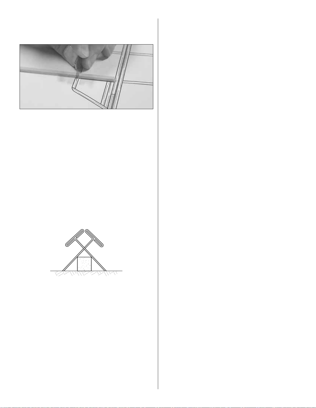
1. The easiest way to cut balsa sticks is with a single-edge
razor blade.To do so, position the stick over the plan, then
place the razor blade on the stick where you wish to cut it.
Press down lightly on the razor blade to mak e a mark where
the stick is to be cut.
2.Take the stick off the plan and cut it over a cutting mat or
a scrap piece of wood
(Okay, if you’re careful you could go
ahead and cut the stick right over the plan, but if y ou do , y ou
may cut through the plan protector, allowing the CA to soak
through and glue the structure to the plan)
.
3. Because of the small balsa sticks used in the tail, small
T-pins may be used to hold the sticks to your building board,
but only where necessary. Use small T-pins (HCAR5100)
or small straight pins found in craft stores.Do not stick pins
into the sticks near the ends, or the wood may split.
4. If you have difficulty with the T-pins splitting the small
sticks, an alternate method is to use the “crossed-pin”
technique. Insert the T-pins into the building board in a
crisscross fashion to hold the sticks to the plan.
5. Only a small amount of CA should be used to glue the
parts together. Use the included CA applicator tips to
control and pinpoint the amount of CA that comes from the
bottle. When the tip becomes clogged, cut the tip off and
continue. In addition to adding unnecessary weight, excess
CA is difficult to sand.If you require additional CA tips, order
number GPMR6033 (5).
6.When applying CA, be careful not to glue your fingers to the
structure. In the process of
un-sticking
your fingers you can
inadvertently damage the structure, thus requiring repairs and
adding weight
(not to mention the aggravation!)
.
7.Sanding requires a light touch to avoid damage.We found
the best method for sanding is to use light strokes in the
direction of the longest sticks. Be certain the sandpaper is
thoroughly bonded to the bar sander.Lifted edges will catch
the structure, causing damage.Use medium-grit sandpaper
such as 120 or 150-grit.
8. One of the best ways to insure a lightweight model is to
proceed slowly and build neatly. Good glue joints with minimal
adhesive are stronger, lighter and have a better appearance
than poor-fitting joints with too much CA.Of course, you should
take this approach with all of your projects!
9.Work over a flat surface .Cover the plan with Great Planes
Plan Protector
™
(GPMR6167) or wax paper so the parts will
not adhere to the plan.
7
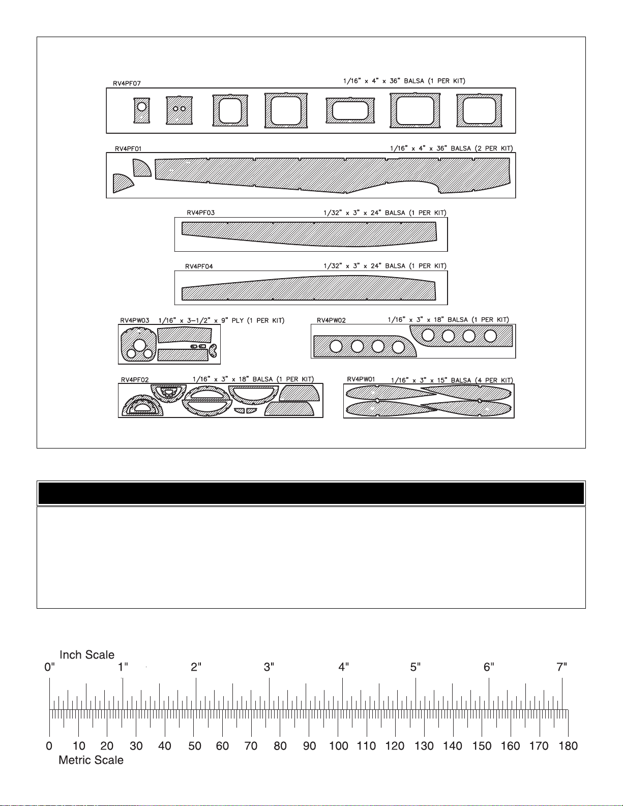
8
DIE-CUT PATTERNS
1/64" = .4 mm
1/32" = .8 mm
1/16" = 1.6 mm
3/32" = 2.4 mm
1/8" = 3.2 mm
5/32" = 4.0 mm
3/16" = 4.8 mm
1/4" = 6.4 mm
3/8" = 9.5 mm
1/2" = 12.7 mm
5/8" = 15.9 mm
3/4" = 19.0 mm
1" = 25.4 mm
2" = 50.8 mm
3" = 76.2 mm
6" = 152.4 mm
12" = 304.8 mm
18" = 457.2 mm
21" = 533.4 mm
24" = 609.6 mm
30" = 762.0 mm
36" = 914.4 mm
METRIC CONVERSIONS
❏ 1. Unroll the plan sheets. Re-roll them inside-out so they
will lie flat. Place the fin/rudder portion of the fuse plan over
your flat building board, then cov er it with Great Planes Plan
Protector or wax paper so glue will not adhere to the plan.
Note: The bottom of the fin is difficult to see on the fuselage
plan. A separate drawing of the fin is located on the wing
plan and may be more useful for building the fin.
❏ 2.Find the four hardest 1/8" x 1/4" x 24" [3.2 x 6.4 x 610mm]
balsa sticks and set them aside for use as the wing spars.
❏ 3. Build the fin and rudder framework from two 1/8" x
1/4" x 24" [3.2 x 6.4 x 610mm] balsa sticks.Hint: Start with
the longest pieces first. If you accidentally cut one piece too
short, use it for a shorter piece somewhere else, thus
minimizing wasted material.
❏ 4. Add the fin and rudder ribs and diagonal braces
from two 1/8" x 1/8" x 24" [3.2 x 3.2 x 610mm] balsa sticks.
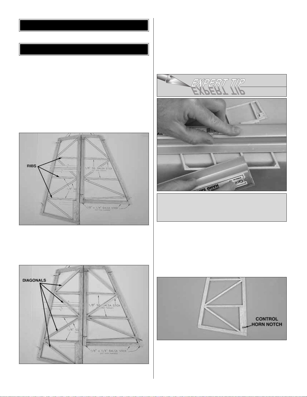
❏ 5. Remove the fin and rudder from the plan. Use a bar
sander with 150-grit sandpaper to carefully sand both sides
of the fin and rudder flat and even. Round the corners as
shown on the plan.Refer to the Expert Tip that follows, then
round the leading edge, top of the fin, trailing edge and top
of the rudder.
❏ 6. Sand a bevel on the leading edge of the rudder as
shown in the cross-section on the plan.
❏ 7. Use a #11 blade to cut the notch in the rudder where
shown on the plan for the laser-cut 1/16" [1.6mm] plywood
control horn. The control horn will be installed into the
notch on the right side of the r udder, but do not glue it into
place until the pushrods are installed during
“Hook Up the
Controls.”
The rudder control horn has an “R” printed on it.
To round the edges of the tail pieces, place one of them
on your workbench so the edge you are rounding extends
just beyond the edge of the bench. Use a bar sander to
hold it down. Use another bar sander to do the sanding.
BUILD THE T AIL SURF A CES
BUILDING INSTRUCTIONS
9
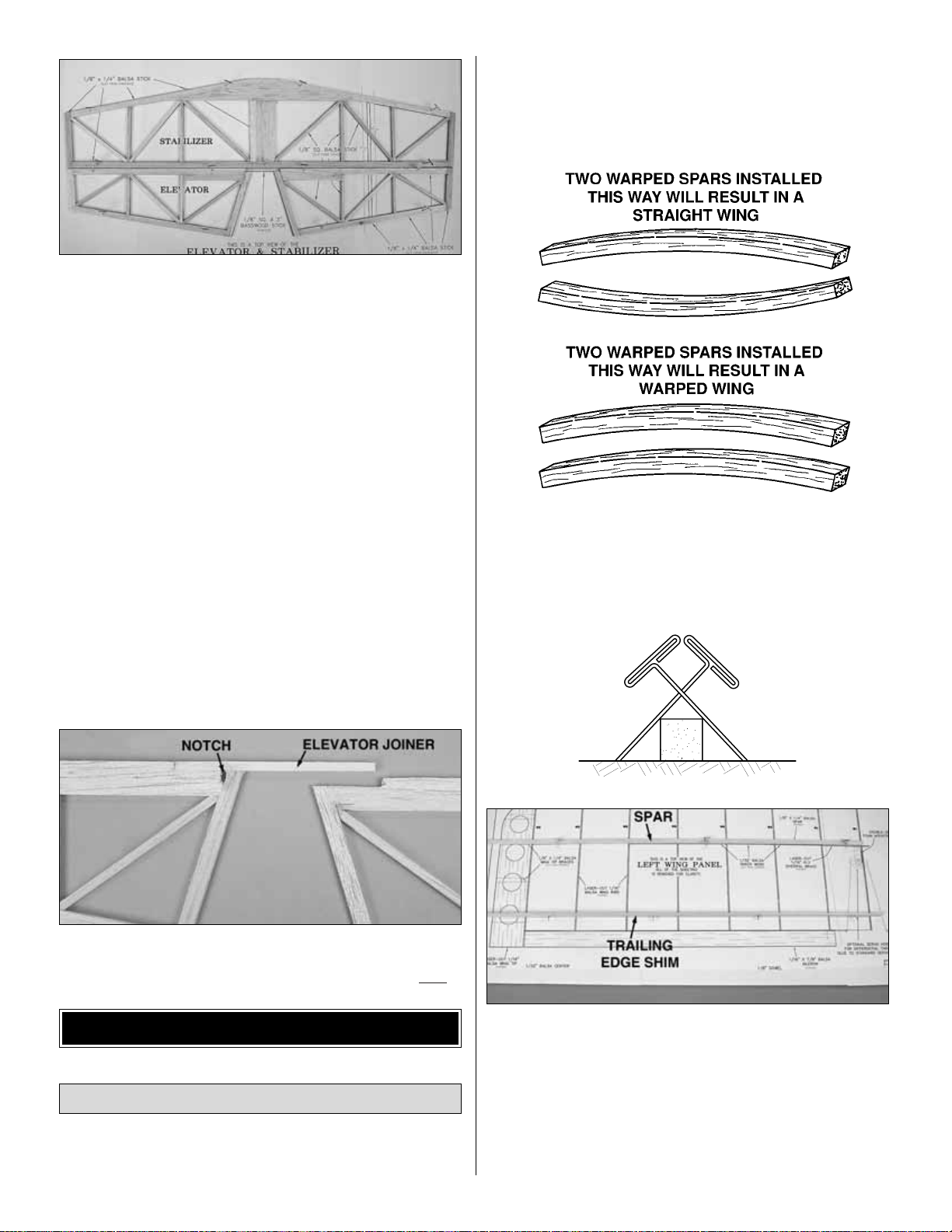
❏ 8.Build the stab and elevators from five 1/8" x 1/4" x 24"
[3.2 x 6.4 x 610mm] and two 1/8" x 1/8" x 24" [3.2 x 3.2 x
610mm] balsa sticks. Be sure to notch the leading edge of
both elevators where the bass w ood joiner stic k goes.Do not
join the elevators with the 1/8" x 1/8" x 3" [3.2 x 3.2 x 76mm]
basswood stick until instructed to do so.
❏ 9. The same as you did the fin and rudder, remove the
stab and elevators from the plans, sand the stab and
elevators flat and even, then round the corners where
shown on the plan.Round the tips of the stab and elevators .
Round the leading edge of the stab and the trailing edge of
the elevators. Bevel the leading edge of both elevators as
shown in the cross-section on the plan.
❏ 10. Use a #11 blade to cut the notch in the left elevator
where shown on the plan for the laser-cut 1/16" [1.6mm]
plywood control horn.The control horn will be installed into
the notch on the bottom of the left elevator, but do not glue
it into place until the pushrods are installed during
“Hook
Up the Controls.”
❏ 11.Use a bar sander with 150-grit sandpaper to bevel the
1/8" x 1/8" x 3" [3.2 x 3.2 x 76mm] basswood elevator
joiner to match the leading edge of the elevators.
❏ 12. Pin both elevators to the plan upside-down. Check the
fit of the elevator joiner and trim if necessary. Use medium CA
to securely glue the elevator joiner to the left elevator only
.
Start by building the left wing panel first so your progress
matches the photos.
❏ ❏ 1. Cover the left wing panel plan with Great Planes
Plan Protector or wax paper.
❏ ❏ 2. Find the four hardest 1/8" x 1/4" x 24" [3.2 x 6.4 x
610mm] balsa sticks you set aside earlier. Match the balsa
main spars so any warps will counteract each other.
❏ ❏ 3. Pin one of the main spars in position over the plan,
aligning one end of the main spar with the outside edge of
the root rib W-1.
❏ ❏ 4. Pin the 1/8" x 3/8" x 24" [3.2 x 9.6 x 610mm] balsa
trailing edge shim in position over the plan, aligning the aft
edge of the stick on the dashed line. The shim should be
standing up with the 1/8" [3.2mm] edge on the table.
Build the Wing Panels
BUILD THE WING
10
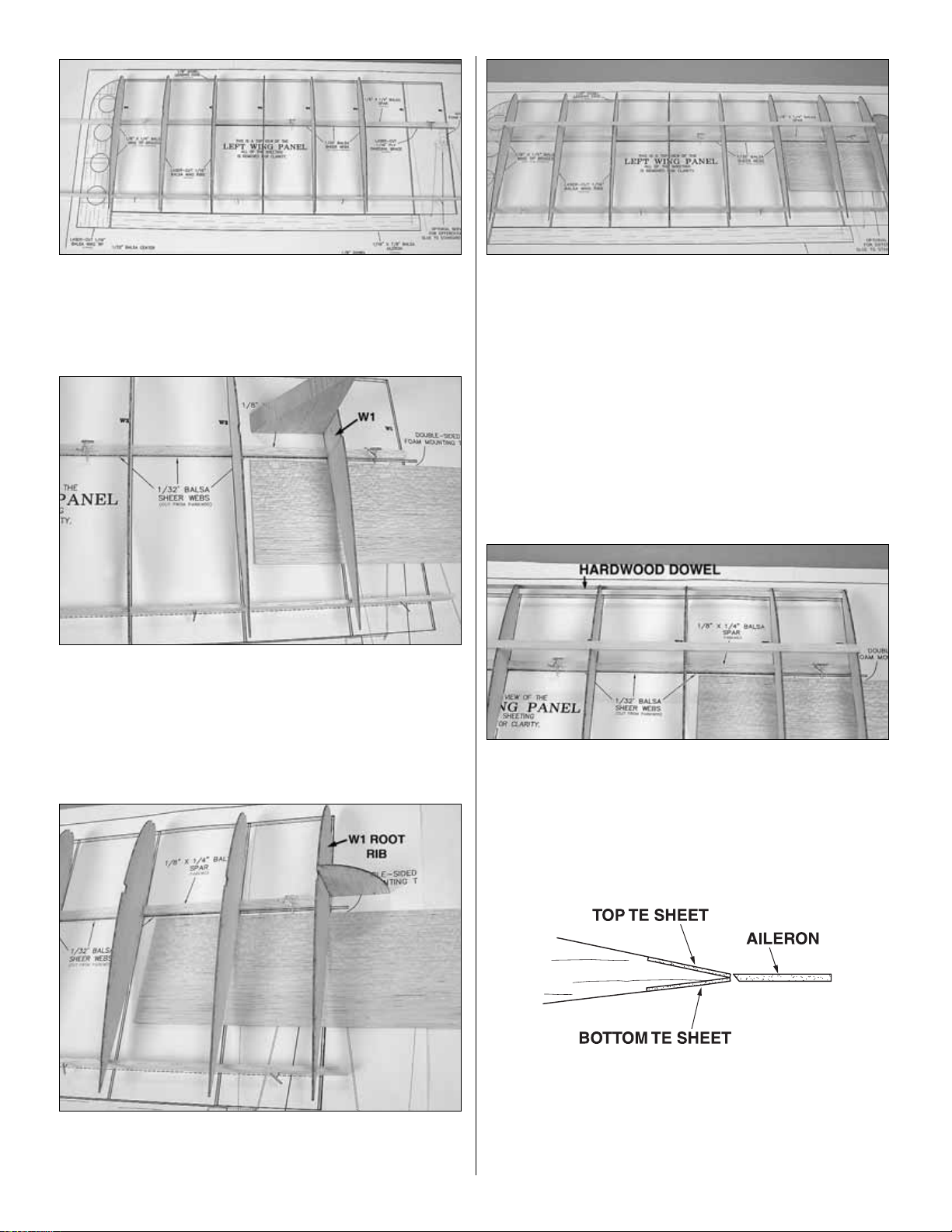
❏ ❏ 5. Starting at the wing tip, glue six laser-cut 1/16"
[1.6mm] balsa W2 ribs over the main spar, perpendicular to
the building board.Important: Pin the rear of the ribs firmly
to the TE shim.
❏ ❏ 6. Temporarily place a sheet of 1/32" [0.8mm] balsa
sheeting on the plan 1/4" [6.4mm] aft of the spar as shown
in the above photo. This will space the W1 ribs properly on
the spar. Glue a laser-cut 1/16" [1.6mm] balsa W1 rib in
place over the main spar as shown in the photo.
❏ ❏ 7. Position a W1 root rib in place over the main spar.
Use the die-cut 1/16" [1.6mm] dihedral gauge to set the rib
at the proper angle before gluing it to the main spar.
❏ ❏ 8.Position the top 1/8" x 1/4" x 24" [3.2 x 6.4 x 610mm]
balsa main spar in the rib notches with one end flush with
the outside edge of the W1 root rib. Glue the spar to all of
the ribs except the W1 root rib .Make sure all ribs, except the
root rib, are perpendicular to the table as you glue each rib
to the top spar.
❏ ❏ 9.Using the dihedral gauge, check that the root rib is still
at the correct angle. Glue the root rib to the top main spar.
Note: Save the dihedral gauge to set the angle of F5A.
❏ ❏ 10. Cut one of the 1/8" x 24" [3.2 x 610mm] hardwood
dowels to length so that it fits in the notches at the front of
the wing ribs, from the root to the tip rib. Glue the dowel to
the ribs.
❏ ❏ 11.Locate a 1/32" x 3/4" x 24" [.8 x 19 x 610mm] balsa
sheet.The sheet should fit in the notches at the trailing edge
of the wing ribs.When the wing is complete, it will blend with
the bottom trailing edge sheet when it is installed later.The
above sketch shows how the completed assembly will look.
11
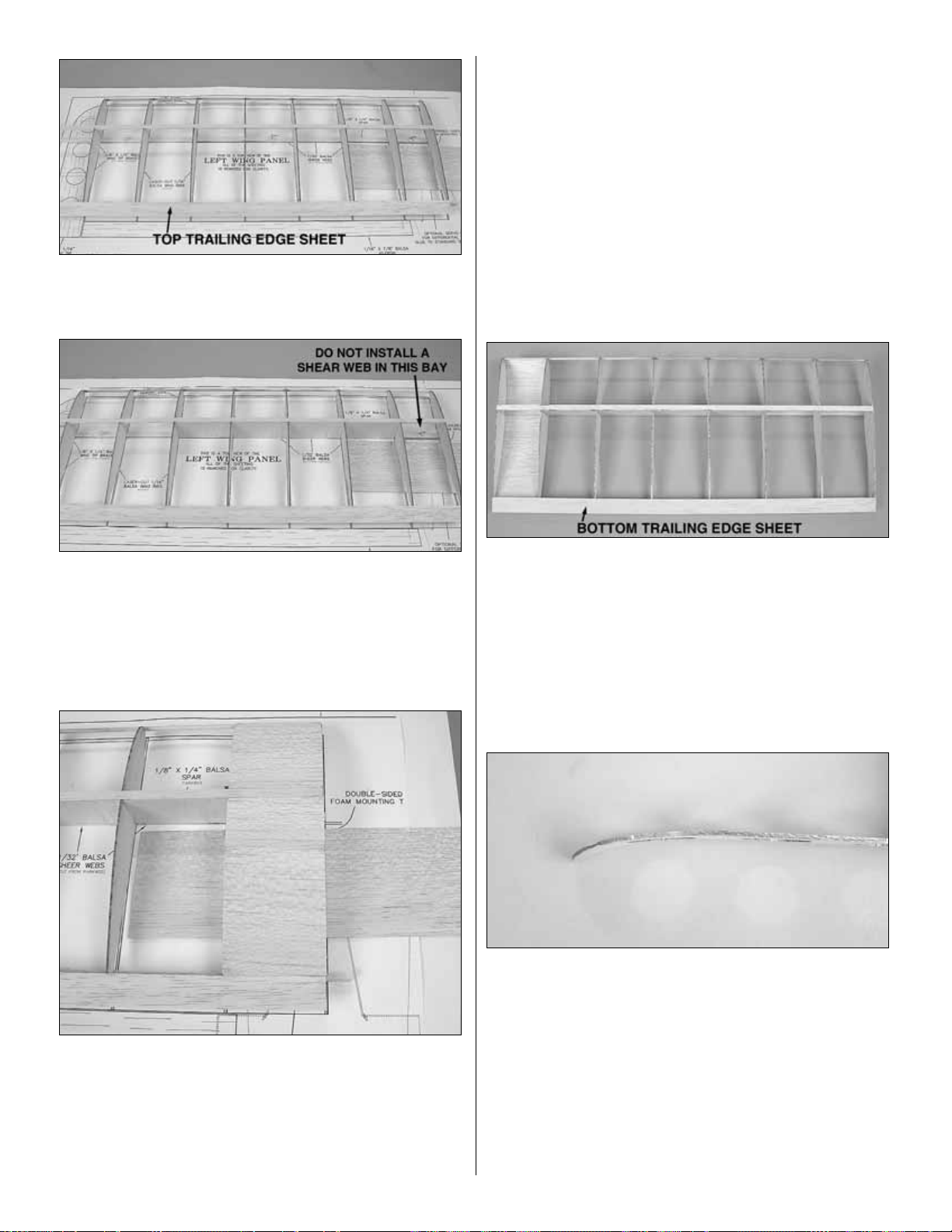
❏ ❏ 12. Glue the top trailing edge sheet to the top of the
wing ribs.
❏ ❏ 13. From a 1/32" x 3" x 15" [0.8 x 76 x 380mm] balsa
sheet, cut and glue shear webs, with the grain running
vertically , to the top and bottom spars in the locations shown
on the plan. It is not necessary for the shear webs to be
glued to the ribs at this time, but make sure they are glued
securely to the wing spars. Do not install shear webs in
the rib bay between the W1 ribs.
❏ ❏ 14. From a 1/32" x 3" x 15" [0.8 x 76 x 380mm] balsa
sheet, cut pieces to make the top center sheeting to fit
between the wing spar and trailing edge sheet and between
the wing spar and the leading edge dowel.Remove any pins
that may be under the area to be sheeted. When satisfied
with the fit, apply medium CA to the top of the W1 ribs and
press the sheeting in place.
❏ ❏ 15. Carefully sand the top center sheeting flush with
the wing spar, leading edge dowel and trailing edge sheet.
❏ ❏ 16. Remove the wing from your building board and
carefully sand off any glue blobs. Cut and sand the wing
spars, leading edge and trailing edge sheeting flush with the
wing tip rib and root rib.
❏ ❏ 17. Reinforce any glue joints that look weak. Glue the
shear webs to each rib. Remember, use glue sparingly to
minimize weight gain.
❏ ❏ 18. Glue a 1/32" x 3/4" x 24" [.8 x 19 x 610mm] balsa
bottom trailing edge sheet to the bottom of the wing ribs
and to the top trailing edge sheet.Trim the sheet even with
the tip and root ribs.
Before proceeding, read steps 19 through 25 to become
familiar with how the wing tip will be installed.
❏ ❏ 19.Prepare the laser-cut 1/16" [1.6mm] balsa wing tip
by carefully bending the forward part of the tip along the
embossed lines.You must do this gently to avoid breaking
part of the tip off. Do not bend along the two short lines that
are used to align the tip with the top wing spar.
Caution: On the left wing tip the embossed lines should be
on top of the wing tip. On the right wing tip the embossed
lines should be on the bottom of the wing tip. Hold the tip
against the wing to determine which way to bend for the
wing tip you are doing!
12
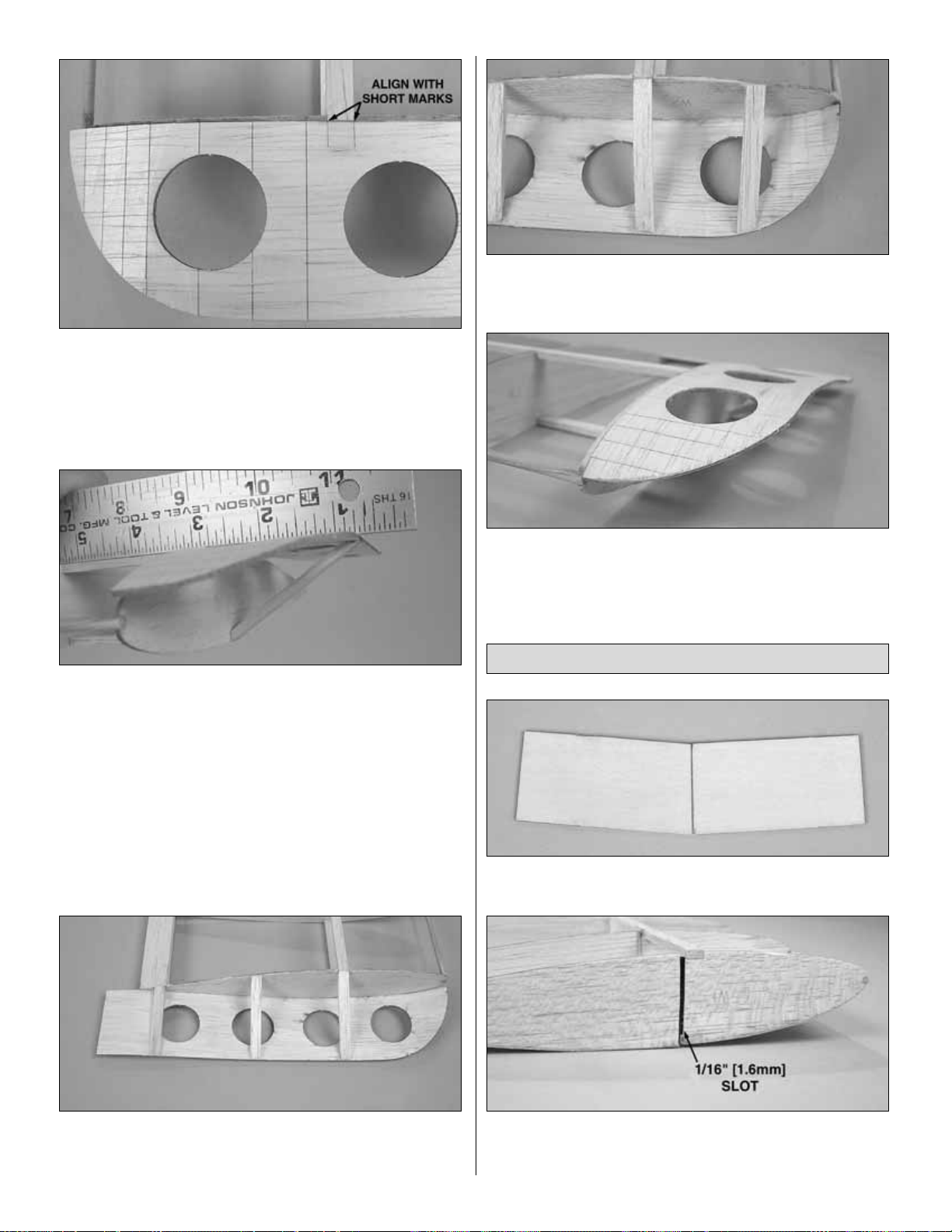
❏ ❏ 20.Align the two short embossed lines on the wing tip
with the top main spar. Spot glue the wing tip to the end of
the wing spar with a small drop of thin CA.
❏ ❏ 21. From a leftover 1/8" x 1/4" [3.2 x 6.4mm] balsa
stick, cut a wing tip brace 2-1/4" [57mm] long. Bevel the
ends of the brace to fit the wing tip as shown in the photo
above. A straightedge can be used along the top spar to
hold the wing tip even and level with the top of the wing.
When satisfied with the fit, glue the brace in place. Hint:
First spot glue the brace to the W2 rib, then glue the end of
the brace to the wing tip while using the straightedge to hold
the wing tip level.
❏ ❏ 22. Glue the rear of the wing tip to the top edge of rib
W2. Make two more wing tip braces and glue them in place
where shown on the plan.
❏ ❏ 23. Glue the front of the wing tip to the top edge of rib
W2. Make one more wing tip brace and glue it in place
where shown on the plan.
❏ ❏ 24.Use a sanding block and 150-grit sandpaper to blend
the wing tip, wing tip braces and the W2 rib together smoothly.
❏ 25. Return to step 1 and build the right wing panel.
Remember! Build it over the right wing plan.
❏ 1. Draw a centerline on the laser-cut 1/16" [1.6mm] ply
dihedral brace.
❏ 2. Using a razor saw and hobby knife, carefully cut a
1/16" [1.6mm] slot in root rib W1, just behind the main spar,
on both wing panels.Test fit the dihedral brace in each slot.
Join the Wing Panels
13
 Loading...