


INSTRUCTION MANUAL
Wingspan: 78.5 in [1995mm] Wing Area: 1180 sq in [76 dm2]
Weight: 14.25 – 16.5 lb [6500g – 7500g] Wing Loading: 27.8 oz/sq ft [85g/dm2] Length: 70 in [1780mm]
Radio: 4-channel minimum (7 to 8 servos) Engine: 1.60 to 2.10 cu in [25 to 35cc] 2-stroke,
2.00 to 3.00 cu in [33 to 50cc] 4-stroke, 2.5 to 3.8 cu in [41 to 65cc] Gas
WARRANTY
Great Planes® Model Manufacturing Co. guarantees this kit to be free from defects in both material and workmanship at the date of purchase. This warranty does not cover any component parts damaged by use or modification. In no case shall Great Planes’ liability exceed the original cost of the purchased kit. Further, Great Planes reserves the right to change or modify this warranty without notice.
In that Great Planes has no control over the final assembly or material used for final assembly, no liability shall be assumed nor accepted for any damage resulting from the use by the user of the final user-assembled product. By the act of using the user-assembled product, the user accepts all resulting liability.
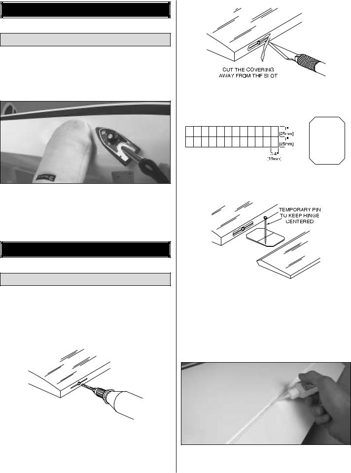
If the buyer is not prepared to accept the liability associated with the use of this product, the buyer is advised to return this kit immediately in new and unused condition to the place of purchase.
READ THROUGH THIS MANUAL BEFORE STARTING CONSTRUCTION. IT CONTAINS IMPORTANT INSTRUCTIONS AND WARNINGS CONCERNING THE ASSEMBLY AND USE OF THIS MODEL.
1610 Interstate Drive Champaign, IL 61822
(217) 398-8970, Ext. 2 airsupport@greatplanes.com
GPMZ0216 for GPMA1305 V1.0 |
Entire Contents © Copyright 2002 |

|
|
|
|
|
.......................................................................APPENDIX |
35 |
||||
|
TABLE OF CONTENTS |
|
|
|||||||
|
|
|
|
FLIGHT TRIMMING.......................................................... |
38 |
|||||
|
|
|
|
|
TAIL WHEEL PUSHROD PATTERN |
39 |
||||
|
|
|
|
|||||||
INTRODUCTION |
2 |
|
ENGINE MOUNT TEMPLATE.......................................... |
39 |
||||||
|
|
|
|
|
|
|
||||
IMAA .................................................................................. |
2 |
|
|
|
|
|
|
|
||
SAFETY PRECAUTIONS .................................................. |
3 |
|
|
|
|
|
|
|
||
DECISIONS YOU MUST MAKE BEFORE |
|
|
|
|
|
|
|
|
|
|
|
|
|
|
|
INTRODUCTION |
|
|
|
||
BEGINNING TO BUILD ..................................................... |
3 |
|
|
|
|
|
|
|||
|
Radio Equipment |
4 |
|
|
|
|
|
|
|
|
|
|
|
|
|
|
|
||||
|
Engine Recommendations........................................... |
4 |
|
The Great Planes 1/4-Scale Patty Wagstaff Extra 300S ARF |
||||||
ADDITIONAL ITEMS REQUIRED ..................................... |
4 |
|
||||||||
|
Hardware & Accessories ............................................. |
4 |
|
is a versatile airplane designed for giant-scale aerobatics. The |
||||||
|
Adhesives & Building Supplies .................................... |
5 |
|
Extra 300S ARF is capable of wild, 3D aerobatics while still |
||||||
|
Optional Supplies & Tools............................................ |
5 |
|
keeping the slow speed and landing performance of a low |
||||||
IMPORTANT BUILDING NOTES....................................... |
5 |
|
wing sport model. The Extra 300S ARF is an airplane that |
|||||||
METRIC/INCH RULER ...................................................... |
6 |
|
will go where you point it without any surprises. |
|||||||
ORDERING REPLACEMENT PARTS............................... |
6 |
|
For the latest technical updates or manual corrections to the |
|||||||
KIT CONTENTS................................................................. |
7 |
|
||||||||
BUILDING INSTRUCTIONS .............................................. |
8 |
|
Extra 300S ARF, visit the web site listed below and select |
|||||||
|
Preparations................................................................. |
8 |
|
the Extra 300S ARF. If there is new technical information or |
||||||
ASSEMBLE THE WING ..................................................... |
8 |
|
changes to this model, a “tech notice” box will appear in the |
|||||||
|
Hook up the Ailerons ................................................... |
8 |
|
upper left corner of the page. |
|
|
|
|||
|
Mount the Wing on the Fuselage............................... |
11 |
|
|
|
http://www.greatplanes.com/airplanes/index.html |
||||
ASSEMBLE THE FUSELAGE ......................................... |
11 |
|
|
|
||||||
|
Install the Servo Tray ................................................. |
11 |
|
|
|
|
|
|
|
|
|
Engine Mounting Preparations .................................. |
12 |
|
|
|
|
|
|
|
|
|
Install the Engine ....................................................... |
13 |
|
|
|
|
|
|
|
|
|
Install a Glow Engine ................................................. |
13 |
|
|
|
|
|
|
|
|
|
..................................................Install a Gas Engine |
15 |
|
|
|
IMAA |
|
|
|
|
|
Install the Cowl .......................................................... |
18 |
|
|
|
|
|
|
|
|
|
|
|
|
|
|
|
||||
|
Install the Tail Surfaces .............................................. |
19 |
|
|
|
|
|
|
|
|
|
Installing the Landing Gear........................................ |
23 |
|
The Extra 300S ARF is an excellent sport-scale model and |
||||||
|
Finish the Radio Installation ...................................... |
26 |
|
is eligible to fly in IMAA events. The IMAA (International |
||||||
|
Finish the Cockpit ...................................................... |
27 |
|
Miniature Aircraft Association) is an organization that |
||||||
|
Apply the Decals........................................................ |
27 |
|
promotes non-competitive flying of giant-scale models. If |
||||||
GET THE MODEL READY TO FLY.................................. |
27 |
|
you plan to attend an IMAA event, contact the IMAA for a |
|||||||
|
Check the Control Directions ..................................... |
27 |
|
copy of the IMAA Safety Code at the address or telephone |
||||||
|
Set the Control Throws .............................................. |
28 |
|
number below. |
|
|
|
|||
|
Balance the Model (C.G.) .......................................... |
28 |
|
|
|
|
|
|
|
|
|
Balance the Model Laterally ...................................... |
29 |
|
|
|
IMAA |
|
|
|
|
PREFLIGHT ..................................................................... |
29 |
|
|
|
205 S. Hilldale Road |
|
|
|
||
|
Identify Your Model..................................................... |
29 |
|
|
|
Salina, KS 67401 |
|
|
|
|
|
Charge the Batteries.................................................. |
29 |
|
(913) 823-5569 |
|
|
|
|||
|
Balance the Propellers............................................... |
29 |
|
|
|
|
|
|
|
|
|
Ground Check............................................................ |
29 |
|
Scale Competition |
|
|
|
|||
|
Range Check |
29 |
|
|
|
|
||||
|
|
Though the Extra 300S is an ARF and may not have the |
||||||||
ENGINE SAFETY PRECAUTIONS |
30 |
|
||||||||
|
same level of detail as an “all-out” scratch-built competition |
|||||||||
AMA SAFETY CODE (excerpt) |
30 |
|
||||||||
|
model, it is a scale model none-the-less and is therefore |
|||||||||
IMAA SAFETY CODE (excerpt) |
30 |
|
||||||||
|
eligible to compete in the Fun Scale |
class in AMA |
||||||||
CHECK LIST |
32 |
|
||||||||
|
competition (we receive many favorable reports of Great |
|||||||||
FLYING |
32 |
|
||||||||
|
Planes ARFs in scale competition!) In |
Fun Scale, the |
||||||||
|
Fuel Mixture Adjustments |
32 |
|
|||||||
|
|
“builder of the model” rule does not apply. To receive the five |
||||||||
|
Takeoff |
33 |
|
|||||||
|
|
points for scale documentation, the only proof required that |
||||||||
|
Flight |
33 |
|
|||||||
|
|
a full-size aircraft of this type in this paint/markings scheme |
||||||||
|
Landing |
33 |
|
|||||||
|
|
did exist is a single sheet such as a kit box cover from a |
||||||||
|
Performance Settings |
33 |
|
|||||||
|
|
plastic model, a photo, or a profile painting, etc. If the photo |
||||||||
|
3D Control Throws |
34 |
|
|||||||
|
|
is in black and white, other written documentation of color |
||||||||
|
3D Servo Arms |
34 |
|
|||||||
|
|
must be provided. Contact the AMA for a rule book with full |
||||||||
|
Servos |
34 |
|
|||||||
|
|
details. |
|
|
|
|||||
|
|
|
|
|
|
|
|
|||
|
|
|
|
2 |
|
|
|
|
|
|
If you would like photos of the full-size Patty Wagstaff Extra 300S for scale documentation, or if you would like to study the photos to add more scale details, photo packs are available from:
Bob’s Aircraft Documentation
3114 Yukon Ave
Costa Mesa, CA 92626 Telephone: (714) 979-8058 Fax: (714) 979-7279 e-mail: www.bobsairdoc.com
PROTECT YOUR MODEL, YOURSELF & OTHERS...FOLLOW THESE IMPORTANT SAFETY PRECAUTIONS
1.Your Extra 300S ARF should not be considered a toy, but rather a sophisticated, working model that functions very much like a full-size airplane. Because of its performance capabilities, the Extra 300S ARF, if not assembled and operated correctly, could possibly cause injury to you or spectators and damage to property.
2.You must assemble the model according to the instructions. Do not alter or modify the model, as doing so may result in an unsafe or unflyable model. In a few cases the instructions may differ slightly from the photos. In those instances the written instructions should be considered as correct.
3.You must take time to build straight, true and strong.
4.You must use an R/C radio system that is in first-class condition, and a correctly sized engine and components (fuel tank, wheels, etc.) throughout the building process.
5.You must correctly install all R/C and other components so that the model operates correctly on the ground and in the air.
6.You must check the operation of the model before every flight to insure that all equipment is operating and that the model has remained structurally sound. Be sure to check clevises or other connectors often and replace them if they show any signs of wear or fatigue.
7.If you are not already an experienced R/C pilot, you should fly the model only with the help of a competent, experienced R/C pilot.
8.While this kit has been flight tested to exceed normal use, if the plane will be used for extremely high stress flying, such as extreme 3D flying, the modeler is responsible for taking steps to reinforce the high stress points.
WARNING: The cowl and wheel pants included in this kit are made of fiberglass, the fibers of which may cause eye, skin and respiratory tract irritation. Never blow into a part (wheel pant, cowl) to remove fiberglass dust, as the dust may blow back into your eyes. Always wear safety goggles, a particle mask and rubber gloves when grinding, drilling and sanding fiberglass parts. Vacuum the parts and the work area thoroughly after working with fiberglass parts.
We, as the kit manufacturer, provide you with a top quality thoroughly tested kit and instructions, but ultimately the quality and flyability of your finished model depends on how you build it; therefore, we cannot in any way guarantee the performance of your completed model, and no representations are expressed or implied as to the performance or safety of your completed model.
Remember: Take your time and follow the instructions to end up with a well-built model that is straight and true.
If you have not flown this type of model before, we recommend that you get the assistance of an experienced pilot in your R/C club for your first flights. If you’re not a member of a club, your local hobby shop has information about clubs in your area whose membership includes experienced pilots.
In addition to joining an R/C club, we strongly recommend you join the AMA (Academy of Model Aeronautics). AMA membership is required to fly at AMA sanctioned clubs. There are over 2,500 AMA chartered clubs across the country. Among other benefits, the AMA provides insurance to its members who fly at sanctioned sites and events. Additionally, training programs and instructors are available at AMA club sites to help you get started the right way. Contact the AMA at the address or toll-free phone number below:
Academy of Model Aeronautics
5151 East Memorial Drive
Muncie, IN 47302
Tele: (800) 435-9262
Fax (765) 741-0057 Or via the Internet at:
http://www.modelaircraft.org
DECISIONS YOU MUST MAKE BEFORE BEGINNING TO BUILD
This is a partial list of items required to finish the Extra 300S ARF that may require planning or decision making before starting to build. Stock numbers are provided in parentheses.
3
Radio Equipment
The Extra 300S ARF can use a simple 4 to 6-channel radio with several “Y” reversing and non-reversing harnesses or it can use a 6 to 10-channel computer radio. Even though the airplane flies fine with a simple radio, we strongly recommend that a computer radio be installed as this will make it easier to obtain the best performance of all flying styles possible with the Extra 300S ARF. Also, all servos used on this airplane should be capable of delivering at least 60 oz-in of torque with the exception of the throttle servo. Digital servos are highly recommended for 3D flying.
Note: Battery selection is also very important. The batteries must be in good condition. To verify this, make sure you cycle them several times before you fly the airplane and that they reach their advertised capacity. If you use 60 oz-in servos on your airplane, the minimum battery size recommended is a 4-cell, 1200mAh battery. If you are using digital servos on your airplane, a 4-cell, 2000mAh battery is the minimum size recommended. Please make sure your batteries are fully charged before each flight, and check and recharge them if needed between flights. A Hobbico® Digital Voltmeter MKIII (HCAP0356) works well for checking your battery voltage. A Hobbico Quick Field Charger™ (HCAM3000) will charge your batteries between flights.
Engine Recommendations
The recommended engine size range for the Extra 300S ARF is 1.60 cu in to 2.10 cu in [25 to 35cc] 2-stroke, 2.00 cu in to 3.00 cu in [33 to 50cc] 4-stroke or 2.5 cu in to 3.8 cu in [41 to 65cc] Gas. Sport style flying will be possible with the lower engine sizes recommended while 3D style flying will require the larger sizes recommended. If an engine in the upper end of the size range is used, throttle management must be practiced. The larger size engines recommended are for 3D style flying which means that the engine is capable of producing several pounds of thrust more than what the model weighs. Full throttle should only be used during straight up maneuvers, never during straight and level flying or while diving as this might over stress the airplane. The airplane has been tested with engines within the recommended range, including the upper end, and it proved to be capable of handling all of them.
The Extra 300S ARF includes the hardware and instructions necessary to install a glow type engine. If you decide to install a gas engine you will need to supply your own fuel tank and hardware necessary to install and run the engine. You may also need to modify the fuel tank supports.
You must not install a larger engine than recommended under any circumstances. Installing a larger engine than recommended will void your warranty and will overstress your airplane to the point where it may break in the air. The airplane is designed and built so that it will fly well with engines within the recommended range.
4
ADDITIONAL ITEMS REQUIRED
Hardware & Accessories
This is the list of hardware and accessories required to finish the Extra 300S ARF. Stock numbers are provided in parentheses.
Engine 1.60 cu in to 2.10 cu in [25 to 35cc] 2-stroke, 2.00 cu in to 3.00 cu in [33 to 50cc] 4-stroke, or 2.7 cu in to 3.8 cu in [44 to 65cc] Gas
Suitable propellers (refer to the engine manufacturer’s recommendations)
Switch and charge jack mounting set (Great PlanesGPMM1000) or (Ernst-ERNM3001)
R/C foam rubber (1/4"-HCAQ1000, or 1/2" HCAQ1050)
If you plan to use a non-computer radio you will also need:
4-Channel radio with seven servos for a glow engine
5-Channel radio with eight servos for a gas engine
(4) 12" Servo extension (ailerons, throttle, elevator, rudder) (HCAM2100 Futaba® )
(2) “Y” harness (rudder, aileron) (HCAM2500)
(1) “Y” harness with servo reverser (elevator) (FUTM4150)
If you plan to use a computer radio you will also need:
7-Channel Radio with seven servos for a glow engine
8-Channel Radio with eight servos for a gas engine.
(3) 12" Servo extension (ailerons, glow throttle) (HCAM2100)
(4) 24" Servo extensions (rudder, elevator) (HCAM2200)
(4) 6" Servo extensions (elevator, ailerons) (HCAM2200)
If you plan to use a glow engine you will also need:
3' Fuel tubing
Great Planes Aluminum Plug (GPMQ4166) or Great Planes Easy Fueler™ Valve for glow (GPMQ4160)
Pitts style muffler for your engine
If you plan to use a gas engine such as the Fuji™ BT 50, you will also need:
3' Gas fuel tubing (GPMQ4133)
Great Planes Aluminum Plug (GPMQ4166) or Great Planes Easy Fueler Valve for gas (GPMQ4161)
Great Planes Ignition Switch Harness (GPMG2150)
36" Plastic pushrod (GPMQ3710)
2-56 x 30" Pushrod (GPMQ3716)
2 Threaded rods for plastic inner rod (GPMQ3831)
2 Plastic clevises (GPMQ3800)
(4) 1/4-20 x 2" Bolts
(4) 1/4-20 Blind nuts (GPMQ3332)
(4) 1/4" Flat washers
Gas tank for gasoline

Adhesives & Building Supplies
In addition to common household tools and hobby tools, this is the “short list” of the most important items required to build the Extra 300S ARF. Great Planes Pro™ CA and Epoxy glue are recommended.
Top Flite® MonoKote® sealing iron (TOPR2100)
Top Flite Panel Line Pen (TOPQ2510)
1/2 oz. Thin Pro CA (GPMR6001)
1/2 oz. Medium Pro CA+ (GPMR6007)
30-Minute Epoxy (GPMR6047)
6-Minute Epoxy (GPMR6042)
Hobby knife (HCAR0105)
#11 Blades (HCAR0211)
Small T-pins (HCAR5100)
Builder’s triangle (HCAR0480)
Electric drill and 1/16" [1.6mm], 5/64" [2.0mm], 3/32" [2.4mm], 7/64" [2.8 mm], #28 (0.136") [3.4mm], 3/16" [4.8mm], 1/4" [6.4mm] drill bits.
Small Phillips and flat blade screwdrivers (HCAR1040)
Pliers with a wire cutter (HCAR0630)
8-32 tap and drill set (GPMR8103) (for glow engine)
Great Planes Pro Threadlocker™ (GPMR6060)
Heat shrink tubing (GPMM1060)
Curved-tip Canopy Scissors for trimming plastic parts (HCAR0667)
Masking tape
Hobbico® solder iron (HCAR0776)
Denatured alcohol
Paper towels
K & S #801 Kevlar® thread string (K+SR4575)
Allen wrenches
Rotary tool such as Dremel® Moto-Tool® (for fiberglass cowl and wheel pants)
Small clamp
Optional Supplies & Tools
Here is a list of optional tools mentioned in the manual that will help you build the Extra 300S ARF.
Top Flite MonoKote heat gun (TOPR2000)
Top Flite Trim Seal Tool (TOPR2200)
Top Flite Precision Magnetic Prop Balancer™ (TOPQ5700)
Top Flite Hot Sock™ iron cover (TOPR2175)
Hobbico Hot Knife™ (HACR0770)
3M “75” spray adhesive (MMMR1900)
Straightedge with scale (HCAR0475)
Cutting mat (HCAR0456)
CA Debonder (GPMR6039)
CA Applicator Tips (HCAR3780)
CA accelerator (GPMR6034)
Epoxy Brushes (GPMR8060)
Mixing Sticks (GPMR8055)
Dead Center™ Engine Mount Hole Locator (GPMR8130)
Great Planes AccuThrow™ Deflection Gauge (for measuring control throws, GPMR2405)
Hobbico Servo Horn Drill (HCAR0698)
Robart Superstand II (ROBP1402)
Single-sided foam tape (wing seating tape, GPMQ4422)
IMPORTANT BUILDING NOTES
•There are two types of screws used in this kit:
Sheet metal screws are designated by a number and a length. For example #6 x 3/4".
This is a number six screw that is 3/4" long.
Machine screws are designated by a number, threads per inch, and a length. SHCS is just an abbreviation for “socket head cap screw” and that is a machine screw with a socket head. For example 4-40 x 3/4".
This is a number four screw that is 3/4" long with forty threads per inch.
•When you see the term test fit in the instructions, it means that you should first position the part on the assembly without using any glue, then slightly modify or custom fit the part as necessary for the best fit.
•Whenever the term glue is written you should rely upon your experience to decide what type of glue to use. When a specific type of adhesive works best for that step, the instructions will make a recommendation.
•Whenever just epoxy is specified you may use either 30-minute (or 45-minute) epoxy or 6-minute epoxy. When 30-minute epoxy is specified it is highly recommended that you use only 30-minute (or 45-minute) epoxy, because you will need the working time and/or the additional strength.
•Photos and sketches are placed before the step they refer to. Frequently you can study photos in following steps to get another view of the same parts.
IMPORTANT: There are many places in this manual where we tell you to reinforce holes made into wood with thin CA. It is important to do this properly to ensure the strongest possible grip of the screw into the wood. The proper procedure is to drill the specified pilot hole first, then run the screw in, remove it, wick thin CA into the hole, allow the CA to cure and reinstall the screw.
5
• The Extra 300S ARF is covered with Top Flite MonoKote film. Should repairs ever be required, MonoKote can be patched with additional MonoKote purchased separately. MonoKote is packaged in six-foot rolls, but some hobby shops also sell it by the foot. If only a small piece of MonoKote is needed for a minor patch, perhaps a fellow modeler would give you some. MonoKote is applied with a model airplane covering iron, but in an emergency a regular iron could be used. A roll of MonoKote includes full instructions for application.
Following are the colors used on this model and order numbers for six foot rolls.
Red–TOPQ0201
Jet White–TOPQ0204
Sapphire Blue–TOPQ0226
Metallic Gold–TOPQ0404
|
|
|
|
|
|
|
|
|
|
|
|
|
|
|
|
|
|
|
|
|
|
|
|
|
|
|
|
|
|
|
|
|
|
|
|
|
|
|
|
|
|
|
|
|
|
|
|
|
|
|
|
|
|
|
|
|
|
|
|
|
|
|
|
|
|
|
|
|
|
|
|
|
|
|
|
|
|
|
|
|
|
|
|
|
|
|
|
|
|
|
|
|
|
|
|
|
|
|
|
|
|
|
|
|
|
|
|
|
|
|
|
|
|
|
|
|
|
|
|
|
|
|
|
|
|
|
|
|
|
|
|
|
|
|
|
|
|
|
|
|
|
|
|
|
|
|
|
|
|
|
|
|
|
|
|
|
|
|
|
|
|
|
|
|
Inch Scale |
|
|
|
|
|
|
|
|
|
|
|
|
|
|
|
To convert inches to millimeters, multiply inches by 25.4 |
|
|
|
|
|
|
|
|
|
|
|
|
|
|
|
|
|
|
|
|
|
|
|
|
|
|
|
|
|
|
|
|||||||||||||||||||||||||||||||||||||||||||||||||||||||||||||||||||||||||||||||||||||||||||||||||||||||||||||||
|
|
|
|
|
|
|
|
|
|
|
|
|
|
|
|
|
|
|
|
|
|
|
|
|
|
|
|
|
|
|
|
|
|
|
|
|
|
|
|
|
|
|
|
|
|
|
|
|
|
|
|
|
|
|
|
|
|
|
|
|
|
|
|
|
|
|
|
|
|
|
|
|
|
|
|
|
|
|
|
|
|
|
|
|
|
|
|
|
|
|
|
|
|
|
|
|
|
|
|
|
|
|
|
|
|
|
|
|
|
|
|
|
|
|
|
|
|
|
|
|
|
|
|
|
|
|
|
|
|
|
|
|
|
|
|
|
|
|
|
||||||||||||||||||||||
0" |
|
|
|
|
|
|
|
|
|
|
|
1" |
|
|
|
|
|
|
|
|
|
|
|
|
|
|
|
2" |
|
|
|
|
|
|
|
|
|
|
|
|
|
|
|
|
|
|
|
3" |
|
|
|
|
|
|
|
|
|
|
|
|
|
|
4" |
|
|
|
|
|
|
|
|
|
|
|
|
|
|
|
|
|
|
5" |
|
|
|
|
|
|
|
|
|
|
|
|
|
|
|
|
|
6" |
|
|
|
|
|
|
|
|
|
|
|
|
|
|
|
|
|
7" |
|
||||||||||||||||||||||||||||||||||||||||||
|
|
|
|
|
|
|
|
|
|
|
|
|
|
|
|
|
|
|
|
|
|
|
|
|
|
|
|
|
|
|
|
|
|
|
|
|
|
|
|
|
|
|
|
|
|
|
|
|
|
|
|
|
|
|
|
|
|
|
|
|
|
|
|
|
|
|
|
|
|
|
|
|
|
|
|
|
|
|
|
|
|
|
|
|
|
|
|
|
|
|
|
|
|
|
|
|
|
|
|
|
|
|
|
|
|
|
|
|
|
|
|
|
|
|
|
|
|
|
|
|
|
|
|
|
|
|
|
|
|
|
|
|
|
|
|
|
|
|
|
|
|
|
|
|
|
|
|
|
|
|
|
|
|
|
|
|
|
|
|
|
|
|
|
|
|
|
|
|
|
|
|
|
|
|
|
|
|
|
|
|
|
|
|
|
|
|
|
|
|
|
|
|
|
|
|
|
|
|
|
|
|
|
|
|
|
|
|
|
|
|
|
|
|
|
|
|
|
|
|
|
|
|
|
|
|
|
|
|
|
|
|
|
|
|
|
|
|
|
|
|
|
|
|
|
|
|
|
|
|
|
|
|
|
|
|
|
|
|
|
|
|
|
|
|
|
|
|
|
|
|
|
|
|
|
|
|
|
|
|
|
|
|
|
|
|
|
|
|
|
|
|
|
|
|
|
|
|
|
|
|
|
|
|
|
|
|
|
|
|
|
|
|
|
|
|
|
|
|
|
|
|
|
|
|
|
|
|
|
|
|
|
|
|
|
|
|
|
|
|
|
|
|
|
|
|
|
|
|
|
|
|
|
|
|
|
|
|
|
|
|
|
|
|
|
|
|
|
|
|
|
|
|
|
|
|
|
|
|
|
|
|
|
|
|
|
|
|
|
|
|
|
|
|
|
|
|
|
|
|
|
|
|
|
|
|
|
|
|
|
|
|
|
|
|
|
|
|
|
|
|
|
|
|
|
|
|
|
|
|
|
|
|
|
|
|
|
|
|
|
|
|
|
|
|
|
|
|
|
|
|
|
|
|
|
|
|
|
|
|
|
|
|
|
|
|
|
|
|
|
|
|
|
|
|
|
|
|
|
|
|
|
|
|
|
|
|
|
|
|
|
|
|
|
|
|
|
|
|
|
|
|
|
|
|
|
|
|
|
|
|
|
|
|
|
|
|
|
|
|
|
|
|
|
|
|
|
|
|
|
|
|
|
|
|
|
|
|
|
|
|
|
|
|
|
|
|
|
|
|
|
|
|
|
|
|
|
|
|
|
|
|
|
|
|
|
|
|
|
|
|
|
|
|
|
|
|
|
|
|
|
|
|
|
|
|
|
|
|
|
|
|
|
|
|
|
|
|
|
|
|
|
|
|
|
|
|
|
|
|
|
|
|
|
|
|
|
|
|
|
|
|
|
|
|
|
|
|
|
|
|
|
|
|
|
|
|
|
|
|
|
|
|
|
|
|
|
|
|
|
|
|
|
|
|
|
|
|
|
|
|
|
|
|
|
|
|
|
|
|
|
|
|
|
|
|
|
|
|
|
|
|
|
|
|
|
|
|
|
|
|
|
|
|
|
|
|
|
|
|
|
|
|
|
|
|
|
|
|
|
|
|
|
|
|
|
|
|
|
|
|
|
|
|
|
|
|
|
|
|
|
|
|
|
|
|
|
|
|
|
|
|
|
|
|
|
|
|
|
|
|
|
|
|
|
|
|
|
|
|
|
|
|
|
|
|
|
|
|
|
|
|
|
|
|
|
|
|
|
|
|
|
|
|
|
|
|
|
|
|
|
|
|
|
|
|
|
|
|
|
|
|
|
|
|
|
|
|
|
|
|
|
|
|
|
|
|
|
|
|
|
|
|
|
|
|
|
|
|
|
|
|
|
|
|
|
|
|
|
|
|
|
|
|
|
|
|
|
|
|
|
|
|
|
|
|
|
|
|
|
|
|
|
|
|
|
|
|
|
|
|
|
|
|
|
|
|
|
|
|
|
|
|
|
|
|
|
|
|
|
|
|
|
|
|
|
|
|
|
|
|
|
|
|
|
|
|
|
|
|
|
|
|
|
|
|
|
|
|
|
|
|
|
|
|
|
|
|
|
|
|
|
|
|
|
|
|
|
|
|
|
|
|
|
|
|
|
|
|
|
|
|
|
|
|
|
|
|
|
|
|
|
|
|
|
|
|
|
|
|
|
|
|
|
|
|
|
|
|
|
|
|
|
|
|
|
|
|
|
|
|
|
|
|
|
|
|
|
|
|
|
|
|
|
|
|
|
|
|
|
|
|
|
|
|
|
|
|
|
|
|
|
|
|
|
|
|
|
|
|
|
|
|
|
|
|
|
|
|
|
|
|
|
|
|
|
|
|
|
|
|
|
|
|
|
|
|
|
|
|
|
|
|
|
|
|
|
|
|
|
|
|
|
|
|
|
|
|
|
|
|
|
|
|
|
|
|
|
|
|
|
|
|
|
|
|
|
|
|
|
|
|
|
|
|
|
|
|
|
|
|
|
|
|
|
|
|
|
|
|
|
|
|
|
|
|
|
|
|
|
|
|
|
|
|
|
|
|
|
|
|
|
|
|
|
|
|
|
|
|
|
|
|
|
|
|
|
|
|
|
|
|
|
|
|
|
|
|
|
|
|
|
|
|
|
|
|
|
|
|
|
|
|
|
|
|
|
|
|
|
|
|
|
|
|
|
|
|
|
|
|
|
|
|
|
|
|
|
|
|
|
|
|
|
|
|
|
|
|
|
|
|
|
|
|
|
|
|
|
|
|
|
|
|
|
|
|
|
|
|
|
|
|
|
|
|
|
|
|
|
|
|
|
|
|
|
|
|
|
|
|
|
|
|
|
|
|
|
|
|
|
|
|
|
|
|
|
|
|
|
|
|
|
|
|
|
|
|
|
|
|
|
|
|
|
|
|
|
|
|
|
|
|
|
|
|
|
|
|
|
|
|
|
|
|
|
|
|
|
|
|
|
|
|
|
|
|
|
|
|
|
|
|
|
|
|
|
|
|
|
|
|
|
|
|
|
|
|
|
|
|
|
|
|
|
|
|
|
|
|
|
|
|
|
|
|
|
|
|
|
|
|
|
|
|
|
|
|
|
|
|
|
|
|
|
|
|
|
|
|
|
|
|
|
|
|
|
|
|
|
|
|
|
|
|
|
|
|
|
|
|
|
|
|
|
|
|
|
|
|
|
|
|
|
|
|
|
|
|
|
|
|
|
|
|
|
|
|
|
|
|
|
|
|
|
|
|
|
|
|
|
|
|
|
|
|
|
|
0 |
10 |
20 |
|
|
|
|
30 |
|
40 |
50 |
|
|
|
|
60 |
70 |
80 |
90 |
|
100 |
|
|
110 |
120 |
130 |
140 |
|
|
150 |
|
160 |
|
|
170 |
180 |
||||||||||||||||||||||||||||||||||||||||||||||||||||||||||||||||||||||||||||||||||||||||||||||||||||||||||||||||||||||||||||||
|
|
|
Metric Scale |
|
|
|
|
|
|
|
|
|
|
|
|
|
|
|
|
|
|
|
|
|
|
|
|
|
|
|
|
|
|
|
|
|
|
|
|
|
|
|
|
|
|
|
|
|
|
|
|
|
|
|
|
|
|
|
|
|
|
|
|
|
|
|
|
|
|
|
|
|
|
|
|
|
|
|
|
|
|
|
|
|
|
|
|
|
|
|
|
|
|
|
|
|
|
|
|
|
|
|
|
|
|
|
|
|
|
|
|
|
|
|
|
|
|
|
|
|
|
|
|
|
|
|
|
|
|
|
|
|
|
|
|
|
|
|
|
|
|||||||||||||||||||||
|
|
|
|
|
|
|
|
|
|
|
|
|
|
|
|
|
|
|
|
|
|
|
|
|
|
|
|
|
|
|
|
|
|
|
|
|
|
|
|
|
|
|
|
|
|
|
|
|
|
|
|
|
|
|
|
|
|
|
|
|
|
|
|
|
|
|
|
|
|
|
|
|
|
|
|
|
|
|
|
|
|
|
|
|
|
|
|
|
|
|
|
|
|
|
|
|
|
|
|
|
|
|
|
|
|
|
|
|
|
|
|
|
|
|
|
|
|
|
|
|
|
|
|
|
|
|
|
|
|
|
|
|
|
|
|
|
|
|
|
|
|
|
|
|
|
|
|
|
|
|
|
|
|
|
|
|
|
|
|
|
|
ORDERING REPLACEMENT PARTS
To order replacement parts for the Great Planes Extra 300S ARF, use the order numbers in the Replacement Parts List that follows. Replacement parts are available only as listed. Not all parts are available separately (an aileron cannot be purchased separately, but is only available with the wing kit). Replacement parts are not available from Product Support, but can be purchased from hobby shops or mail order/Internet order firms. Hardware items (screws, nuts, bolts) are also available from these outlets. If you need assistance locating a dealer to purchase parts, visit www.greatplanes.com and click on “Where to Buy.” If this kit is missing parts, contactGreat Planes Product Support.
|
Replacement Parts List |
|
Order Number |
Description |
How to Purchase |
|
Missing pieces ...................... |
Contact Product Support |
|
Instruction manual................. |
Contact Product Support |
|
Full-size plans ....................... |
Not available |
GPMA2329...................................... |
Wing Tube |
|
GPMA2330...................................... |
Wing Set |
|
GPMA2331...................................... |
Fuselage |
|
GPMA2332...................................... |
Stab Set |
|
GPMA2333...................................... |
Rudder |
Contact Your Hobby |
GPMA2334...................................... |
Landing Gear |
................ Supplier to Purchase |
GPMA2335...................................... |
Wheel Pants Set |
These Items |
GPMA2336...................................... |
Canopy |
|
GPMA2337...................................... |
Cowl |
|
GPMA2338...................................... |
Decal Set |
|
GPMA2339...................................... |
Stab Tubes (2) |
|
6
|
|
|
|
|
|
KIT CONTENTS |
|
|
|
|
|
|
|
|
|
|
|
|
|
|
Before starting to build, use the |
Contents list to take an inventory of this kit to make sure it is complete, and inspect the |
|
|
parts to make sure they are |
quality. If any parts are missing or are not of acceptable quality, or if you need |
|
|
assistance with assembly, |
Great Planes Product Support. When reporting defective or missing parts, use the part |
|
|
names exactly as they are written |
the Kit Contents list on this page. |
|
|
|
Great Planes Product Support: |
|
|
|
Telephone: (217) 398-8970 |
|
|
|
Fax: (217) 398-7721 |
|
|
|
E-mail: airsupport@greatplanes.com |
|
|
|
|
|
|
|
|
|
|
|
|
|
|
|
|
|
|
|
|
|
|
|
|
|
|
|
|
|
|
|
|
|
|
|
|
|
|
|
|
|
|
|
|
|
|
|
|
|
|
|
|
|
|
|
|
|
|
|
|
|
|
|
|
|
|
23 |
|
|
|
|
|
|
|
|
|
|
|
|
|
|
|
|
|
|
|
|
|
|
|
|
|
|
|
|
|
|
|
|
|
|
|
|
||
|
|
|
|
|
|
|
|
|
|
|
|
|
|
|
|
|
|
|
|
|
|
|
|
|
|
|
|
|
|
|
|
|
|
|
|
|
|
|
|
|
|
|
|
|
|
|
|
|
|
|
|
|
|
|
|
|
|
|
|
|
|
|
|
|
|
|
|
|
|
|
|
|
|
|
|
|
|
|
|
|
|
|
|
|
|
|
|
|
|
|
|
|
|
|
|
|
|
|
|
|
|
|
|
|
|
|
|
|
|
|
|
|
|
|
|
|
|
|
|
|
|
|
|
|
|
|
|
|
|
|
|
|
|
|
|
|
|
|
|
|
|
|
|
|
|
|
|
|
|
|
|
|
|
|
|
|
|
|
|
|
|
|
|
|
|
|
|
|
|
|
|
|
|
|
|
|
|
|
|
|
|
|
|
|
|
|
|
|
|
|
|
|
|
|
|
|
|
|
|
|
|
|
|
|
|
|
|
|
|
|
|
|
|
|
|
|
|
|
|
|
|
|
|
|
|
|
|
|
|
|
|
|
|
|
|
|
|
|
|
|
|
|
|
|
|
|
|
|
|
|
|
|
|
|
|
|
|
22 |
|
|
|
|
|
|
|
|
|
|
|
|
|
|
|
|
|
|
|
|
|
|
|
|
|
|
|
|
|
|
|
|
|
|
|
|
|
|
|
||
|
|
|
|
|
|
|
|
|
|
|
|
|
|
|
|
|
|
|
|
|
|
|
|
|
|
|
|
3 |
|
|
|
|
|
|
|
|
|
|
|
|
|
|
|
|
|||||
|
|
|
21 |
|
|
|
|
|
|
|
|
|
|
|
|
|
|
|
|
|
|
|
|
|
|
|
|
|
|
|
|
|
|
|
|
|
|
|
|
|
|
|
|
|
|
||||
|
|
|
|
|
|
|
|
|
|
|
|
|
|
|
|
|
|
|
|
|
|
|
|
|
|
|
|
|
|
|
|
|
|
|
|
|
|
|
|
|
|
|
|
|
|
|
|
||
|
|
|
|
|
|
|
|
|
|
|
|
|
|
|
|
|
|
|
|
|
|
|
|
|
|
|
|
|
|
|
|
|
|
|
|
|
|
|
|
|
|
|
|
||||||
|
|
|
|
|
|
|
|
|
|
|
|
|
|
|
|
|
|
|
|
|
|
|
|
|
|
|
|
|
|
|
|
|
|
|
|
|
|
|
|
|
|
|
|
|
|||||
|
|
|
|
|
|
|
|
|
|
|
|
|
|
|
|
|
|
|
|
|
|
|
|
|
|
|
|
|
|
|
|
|
|
|
|
|
|
4 |
|
|
|||||||||
|
|
|
|
|
20 |
|
|
|
|
|
|
|
|
|
|
|
|
|
|
|
|
|
|
|
|
|
|
|
|
|
|
|
|
|
|
|
|
|
|
|
|||||||||
|
|
|
|
|
|
|
1 |
|
|
|
|
|
|
|
|
|
|
|
|
|
|
|
|
|
|
||||||||||||||||||||||||
|
|
|
|
|
|
|
|
|
|
|
|
|
|
|
|
|
|
|
|
|
|
|
|
|
|
|
|
|
|
|
|
|
|
|
|
|
|
|
|
|
|
|
|
|
|
|
|||
|
|
|
|
|
|
|
|
|
|
|
|
|
|
|
|
|
|
|
|
|
|
|
|
|
|
|
|
|
|
|
|
|
|
|
|
|
|
|
|
|
5 |
|
|
|
|
|
|
|
|
|
|
|
|
19 |
|
|
|
|
|
|
|
|
|
|
|
|
|
|
|
|
|
|
|
|
|
|
|
|
|
|
|
|
|
|
|
|
|
|
|
|
|
|
|
|
|
|
|||
|
|
|
|
|
|
|
|
|
|
|
|
|
|
|
|
|
|
|
|
|
|
|
|
|
|
|
|
|
|
|
|
|
|
|
|
|
|||||||||||||
|
|
|
|
|
|
|
|
|
|
|
|
|
|
|
|
|
|
|
|
|
|
|
|
|
|
|
|
|
|
|
|
|
|
|
|
|
|
|
|
|
|
|
|
|
|
|
|
||
|
|
|
|
|
|
|
|
|
|
|
|
|
|
|
|
|
|
|
|
|
|
|
|
|
|
|
|
|
|
|
|
|
|
|
|
|
|
|
|
|
|
|
|
|
|
|
|
|
|
|
|
|
|
|
|
|
|
|
|
|
|
|
|
|
|
|
|
|
|
|
|
|
|
|
|
|
|
|
|
|
|
|
|
|
|
6 |
|
|
|
|
|
|
|
|
|
|
|
|
|
|
|
|
|
|
|
|
|
|
|
|
|
|
|
|
|
|
|
|
|
|
|
|
|
|
|
|
|
|
|
|
|
|
|
|
|
|
|
|
|
|
|
|
|
|
|
|
|
||
|
|
|
|
|
|
|
|
|
|
|
|
|
|
|
|
|
|
|
|
|
|
|
|
|
|
|
|
|
|
|
|
|
|
|
|
|
|
|
|
|
|
|
|
|
|
|
|
||
|
|
|
|
|
|
|
|
|
|
|
|
|
|
|
|
|
|
|
|
|
|
|
|
|
13 |
|
|
|
|
|
|
|
|
|
|
|
|
|
|
|
|
|
|
|
|
|
|
|
|
|
|
|
|
|
|
|
|
|
|
|
|
|
|
|
|
|
|
|
|
|
|
25 |
|
|
|
|
|
11 |
|
|
|
|
|
|
|
|
|
|
|
|
|
|
|
|
|
|
|||
|
|
|
|
|
|
|
|
|
|
|
|
|
|
|
|
|
|
|
|
|
|
|
|
|
|
|
|
|
|
|
|
|
|
|
|
|
|
|
|
|
|
||||||||
|
|
|
|
|
|
|
|
|
|
|
|
|
|
|
|
|
|
|
|
|
|
|
|
|
|
|
|
|
|
|
|
|
|
|
|
|
|
|
|
|
|||||||||
|
|
|
|
|
|
|
|
|
|
|
|
|
|
|
|
|
|
|
|
|
|
|
|
|
|
|
|
|
|
|
|
|
|
|
|
|
|
|
|
|
|
|
|
|
|
|
|
|
|
|
|
|
|
|
|
|
|
|
|
|
|
|
|
|
|
|
|
|
|
|
|
|
|
|
|
|
|
|
|
|
|
|
|
|
|
|
|
|
|
|
|
|
|
|
|
|
|
|
|
|
|
|
|
|
|
|
|
|
|
|
17 |
|
|
|
|
|
|
|
|
|
|
|
|
|
|
|
|
|
|
|
|
|
|
|
|
|
|
|
|
|
|
|
|
|
|
|
|
||
|
|
|
|
|
|
|
|
|
|
|
|
|
|
|
|
|
|
|
|
|
|
|
|
|
|
|
|
|
|
|
|
|
|
|
|
|
|
||||||||||||
|
|
|
|
|
|
|
|
|
|
|
|
|
|
|
|
|
|
|
|
|
|
|
|
|
|
|
|
|
|
|
|
|
|
|
|
|
|
||||||||||||
|
|
|
|
|
|
|
|
|
|
|
|
|
|
|
|
|
|
|
|
|
|
|
|
|
|
|
|
|
|
|
|
|
|
|
|
|
|
|
|
|
|
|
|
|
|
|
|||
|
|
|
|
|
|
|
|
|
|
|
|
|
|
|
|
|
|
|
|
|
|
15 |
|
|
|
|
|
|
|
|
|
|
|
|
|
|
|
|
|
|
|
|
|
|
|
|
|
|
|
|
|
|
|
|
|
|
|
|
|
|
|
|
|
|
|
|
|
|
|
|
|
|
|
|
|
|
|
|
|
|
|
|
|
|
|
|
|
|
|
|
|
|
|
|
|
||||
|
|
|
|
|
|
|
|
|
|
|
|
|
|
|
|
|
|
|
|
|
|
|
|
|
|
|
|
|
|
|
|
|
|
|
|
|
|
|
8 |
|
|
|
|
||||||
|
|
|
|
|
|
|
|
|
|
|
|
|
|
|
|
|
|
|
|
|
|
|
|
|
|
|
|
|
|
|
|
|
|
|
|
|
|
|
|
|
|
|
|
|
|
|
|
||
|
|
|
|
|
|
|
|
|
|
|
|
|
|
|
|
|
|
|
|
|
|
|
|
|
|
|
|
|
|
|
|
|
|
|
|
|
|
|
|
|
|
|
|
|
|
|
|
||
|
|
|
|
|
|
|
|
|
|
|
|
|
|
|
|
|
|
|
|
|
|
|
|
|
|
|
|
|
|
|
|
|
|
|
|
|
|
|
|
|
|
|
|
|
|
|
|
|
|
|
|
|
|
|
|
|
|
|
|
|
|
|
|
|
|
|
|
|
|
|
|
|
|
|
|
|
|
|
|
|
|
|
|
|
|
|
|
|
|
|
|
|
|
|
|
|
|
|
|
|
|
|
|
|
|
|
|
|
|
|
|
|
|
|
|
|
|
|
|
|
|
|
|
|
|
|
|
|
|
|
|
|
|
|
|
|
|
|
|
|
|
|
|
|
|
|
|
|
|
|
|
|
|
|
|
|
|
|
|
|
|
|
|
|
|
|
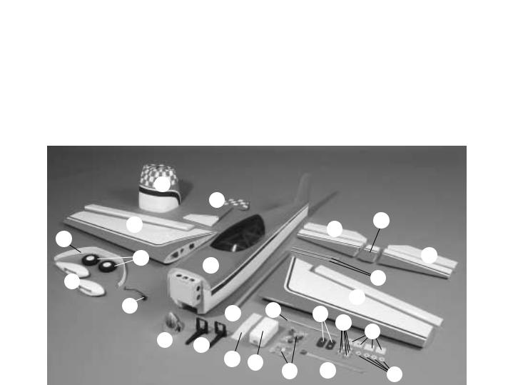
Kit Contents (Photographed) |
|
|
|
|
|
|
|
|
|
|
|
|
|
|
|
|
|
|
|
|
|
|||||||||||
1. |
Fuselage & Canopy |
|
10. |
|
(8) 4-40 x 12" Metal Pushrods |
|
|
|
|
|
|
|
|
|
|
Tail Wheel Assembly |
|||||||||||||||||||||||||||||||||
|
|
|
|
|
|
|
|
18. |
|
||||||||||||||||||||||||||||||||||||||||
2. |
Stab Center Section |
|
11. |
|
(2) Aileron Servo Covers |
|
|
|
|
|
|
19. |
|
(2) Fiberglass Wheel Pants |
|||||||||||||||||||||||||||||||||||
3. |
Right Stab Half and Elevator |
|
12. |
|
(2) Hardware Bags (contents listed |
20. |
|
(2) 4" Wheels |
|||||||||||||||||||||||||||||||||||||||||
4. |
Left Stab Half and Elevator |
|
|
|
below) |
|
|
|
|
|
|
|
|
|
|
21. |
|
Landing Gear |
|||||||||||||||||||||||||||||||
5. |
Aluminum Stab Mounting Tubes |
|
13. |
|
Hardwood Stick |
|
|
|
|
|
|
|
|
|
|
22. |
|
Right Wing and Aileron |
|||||||||||||||||||||||||||||||
6. |
Left Wing and Aileron |
|
14. |
|
Fuel Tank |
|
|
|
|
|
|
|
|
|
|
23. |
|
Fiberglass Cowl |
|||||||||||||||||||||||||||||||
7. |
(4) Ply Wheel Pant Mounts |
|
15. |
|
CA Hinge Material |
|
|
|
|
|
|
|
|
|
|
24. |
|
Rudder |
|||||||||||||||||||||||||||||||
8. |
(4) Ply Wing Washers |
|
16. |
|
Engine Mount |
|
|
|
|
|
|
|
|
|
|
25. |
|
Aluminum Wing Tube |
|||||||||||||||||||||||||||||||
9. |
(5) Hardwood Cowl Blocks |
|
17. |
|
4" Aluminum Spinner |
|
|
|
|
|
|
|
|
|
|
|
|
|
|
|
|
|
|
|
|
|
|||||||||||||||||||||||
|
|
|
|
|
|
|
|
|
|
|
|
|
|
|
|
|
|
|
|
|
|
|
|
|
|
|
|
|
|
|
|
|
|
|
|
|
|
|
|
|
|
|
|
|
|
|
|
|
|
|
|
|
|
|
|
|
|
|
|
|
|
|
|
|
|
|
|
|
|
|
|
|
|
|
|
|
|
|
|
|
|
|
|
|
|
|
|
|
|
|
|
|
|
|
|
|
|
|
|
|
|
|
|
|
|
|
|
|
|
|
|
|
|
|
|
|
|
|
|
|
|
|
|
|
|
|
|
|
|
|
|
|
|
|
|
|
|
|
|
|
|
|
|
|
|
|
|
|
|
|
|
|
|
|
|
|
|
|
|
|
|
|
|
|
|
Kit Contents (Not Photographed) |
|
|
|
|
|
|
|
|
|
|
|
|
|
|
|
||||||||||||||||||
|
|
|
|
|
|
|
|
|
|
|
|
|
|
1/4 -20 x 2" Nylon Bolt |
|
|
|
|
|
|
|
|
|
#8 Lock Washer |
|||||||||||||||||||||||||
(8) 4-40 x 12" Threaded One End Pushrods |
(4) |
|
|
|
|
|
|
(8) |
|||||||||||||||||||||||||||||||||||||||||
(4) 4-40 x 3/4" Bolts |
(1) |
6-32 Torque Rod Horn |
|
|
|
|
|
|
(4) |
#2 x 3/8" Screw |
|||||||||||||||||||||||||||||||||||||||
(2) Nylon Tail Wire Straps |
(1) |
Large Quick Connector |
|
|
|
|
|
|
(4) |
#2 Washers |
|||||||||||||||||||||||||||||||||||||||
(8) 4-40 Threaded Metal Clevises |
(1) |
Retainer For Quick Connector |
|
|
|
|
|
|
(8) |
4-40 Hex Nuts |
|||||||||||||||||||||||||||||||||||||||
(7) 4-40 Solder Metal Clevises |
(7) |
#4 Flat Washers |
|
|
|
|
|
|
|
|
|
|
(2) |
#4 x 3/4" Screw |
|||||||||||||||||||||||||||||||||||
(8) 8-32 x 1" Socket Head Cap Screw |
(3) |
4-40 x 1/4" Socket Head Cap Screw |
(4) |
Nylon Dowels |
|||||||||||||||||||||||||||||||||||||||||||||
(15) Silicone Retainers |
(2) |
2" x 3/16" Axles |
|
|
|
|
|
|
|
|
|
|
(6) |
Giant-Scale Control Horns |
|||||||||||||||||||||||||||||||||||
(9) 8-32 Blind Nuts |
(2) |
Large Axles Nuts |
|
|
|
|
|
|
|
|
|
|
(1) |
#64 Rubber Band |
|||||||||||||||||||||||||||||||||||
(33) #4 x 5/8" Screws |
(2) |
3/16" Wheel Collars |
|
|
|
|
|
|
|
|
|
|
(2) |
3mm x 250mm Hardwood Dowel |
|||||||||||||||||||||||||||||||||||
(13) #8 Flat Washers |
(2) |
6-32 x 1/8" Socket Head Set Screws |
(1) |
Landing Gear Cover |
|||||||||||||||||||||||||||||||||||||||||||||
(5) 8-32 x 1" Phillips Screw |
(4) |
#4 x 3/8" Screws |
|
|
|
|
|
|
|
|
|
|
|
|
|
|
|
|
|
|
|
|
|
|
|
|
|
||||||||||||||||||||||
(2) 1/8" Wheel Collar |
(4) |
1/4-20 Blind Nuts (installed in wing) |
|
|
|
|
|
|
|
|
|
|
|
|
|
|
|
||||||||||||||||||||||||||||||||
|
|
|
|
|
|
|
|
|
|
|
|
|
|
|
|
|
|
|
|
|
|
|
|
|
|
|
|
|
|
|
|
|
|
|
|
|
|
|
|
|
|
|
|
|
|
|
|
|
|
|
|
|
|
|
|
|
|
|
|
|
|
|
|
|
|
7 |
|
|
|
|
|
|
|
|
|
|
|
|
|
|
|
|
|
|
|
|
|
|
|
|
|
||||||||
BUILDING INSTRUCTIONS
Preparations
1. If you have not done so already, remove the major parts of the kit from the box (wings, fuselage, cowl, tail parts, etc.) and inspect them for damage. If any parts are damaged or missing, contact Product Support at the address or telephone number listed in the front cover.
2. Remove the masking tape and separate the ailerons from the wing and the elevators from the stab. Use a covering iron with a covering sock on high heat to tighten the model’s covering if necessary. Apply pressure with a Hot Glove over sheeted areas to thoroughly bond the covering to the wood.
ASSEMBLE THE WING
Hook Up the Ailerons
1. The first steps in the construction of this wing will be the installation of the ailerons and the aileron servos. The process described here will explain how to install the right aileron and the right aileron servo. The process has to be repeated again to install the left aileron and the left aileron servo, or you can work on both at the same time.
DRILL A 3/32" HOLE 1/2" DEEP, IN CENTER OF HINGE SLOT
2. Locate the pre-cut hinge slots on the wing’s trailing edge and the leading edge of the aileron. Drill a 3/32" [2.4mm] hole, 1/2" [12mm] deep in the center of each hinge slot to allow the CA to “wick” in. Follow-up with a #11 blade to clean out the slots. Hint: If you have one, use a highspeed rotary tool to drill the holes.
8
3. Use a sharp #11 blade to cut a strip of covering from the hinge slots in the wing and aileron.
4. Cut five 3/4" x 1" [19mm x 25mm] hinges from the CA hinge strip. Snip off the corners so they go in easier.
5. Test fit the ailerons to the wing with the hinges. If the hinges do not remain centered, stick a pin through the middle of the hinge to hold it in position.
6. Remove any pins you may have inserted into the hinges. Adjust the aileron so that there is a small gap between the LE of the aileron and the wing. The gap should be small–just enough to see light through or to slip a piece of paper through.
7. Apply six drops of thin CA to the top and bottom of each hinge. Do not use CA accelerator. After the CA has fully hardened, test the hinges by pulling on the aileron.
8. Feel through the MonoKote covering on the bottom surface of the wing and find the opening for the aileron servo. Cut the covering 1/8" [3.2mm] inside the opening. Use a sealing iron or trim seal tool to seal the covering to the edges of the opening.
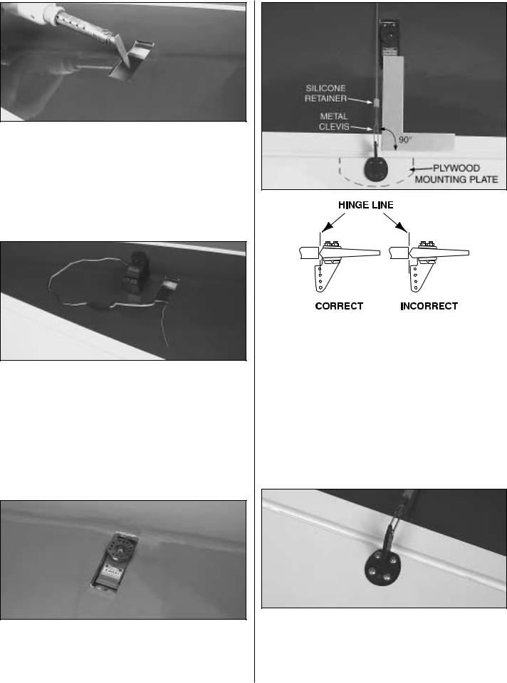
9. Connect one 12" [305mm] servo lead extension to the aileron servo. Use heat shrink tubing or tape to secure the connection. Tie the string inside the aileron servo opening to the aileron servo lead. Pull the servo lead out of the end of the wing with the string.
10. Test fit the servo in the opening and trim the opening if necessary. Mark the location of the servo mounting screws and drill 1/16" [1.6mm] holes at the marks. Wick some thin CA in the holes you just made and install the aileron servo with the hardware that was supplied with it.
11. Install a threaded metal clevis approximately 18 full turns onto one of the 12" [305mm] threaded one end pushrods. Connect the clevis to a large nylon control horn and slip a silicone retainer onto it. Align the pushrod 90 degrees to the aileron’s edge as shown above and mark the control horn’s holes on the aileron. Make sure that the control horn is positioned on the aileron’s plywood mounting plate.
12. Use a 1/16" [1.6mm] drill bit to drill the control horn’s screw holes. Wrap masking tape 1/4" [6.4mm] from the end of the bit as a guide to keep from drilling the holes too deep. Do not drill through. Wick some thin CA into the holes and mount the control horn using four #4 x 5/8" [16mm] screws. It is important that you use thin CA to strengthen the holes.
9
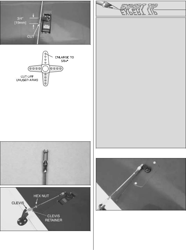
13. Cut up a servo arm and center it so that the servo arm is 90 degrees to the pushrod. Center the aileron and mark on the pushrod where it meets with the servo arm’s hole. Make another mark 3/4" [19mm] closer to the threaded metal clevis. Cut the wire at the second mark.
14. Solder an unthreaded metal clevis on the pushrod as shown. Install a 4-40 hex nut on the threaded end of the pushrod. Slip a silicone retainer onto the clevis and install the clevis on the servo arm. Install the servo arm on the servo.
HOW TO SOLDER
A.Use denatured alcohol or other solvent to remove residual oil from the pushrod.
B.Use coarse sandpaper to thoroughly roughen the end of the pushrod where it is to be soldered.
C.Apply a few drops of soldering flux to the end of the pushrod, then use a soldering iron or a torch to heat the end of the pushrod. Coat the end of the pushrod with silver solder (GPMR8070) by touching the solder to the pushrod. The heat of the pushrod should melt the solder–not the flame of the torch or soldering iron–thus allowing the solder to flow. Note: Do not use silver solder for electrical soldering.
D.Join the clevis to the pushrod. Add another drop of flux, then heat and add solder. The same as before, the heat of the parts being soldered should melt the solder thus allowing it to flow. Allow the joint to cool without disturbing. Avoid excess blobs, but make certain the joint is thoroughly soldered. The solder should be shiny, not rough. If necessary, heat the joint again and allow to cool slowly without disturbing.
E.After the joint has solidified but while it is still hot, carefully use a cloth to wipe away soldering flux. Important: After the joint cools, coat with oil to protect it from corrosion. When finished, the solder joint should appear shiny not dull. If it is dull when it cools, it is a cold joint and not very strong. Simply reheat the cold joint to correct this problem.
15. Find the pre-painted ABS aileron servo cover. Locate it over the aileron servo and mark the mounting holes on the wing sheeting. Remove the cover and drill 1/16" [1.6mm] holes through the wing sheeting at the marks. Wick thin CA into the holes and install the aileron servo covers in place with two #2 x 1/4" [6.4mm] screws and two #2 washers. Install the aileron pushrod in place. Secure the servo arm in place with the servo screw. Adjust the length of the pushrod and tighten the hex nut against the threaded clevis.
10
16. Find the four white nylon anti-rotation pins. Locate the holes in the wings for the pins. Mix a small amount of 30-minute epoxy and glue the anti-rotation pins in place. Once inserted the pins should stick out about 1/2" [13mm]. Clean up any excess epoxy with a paper towel dampened with denatured alcohol.
17. If you have not done so, go back to step #1 and finish the left wing the same way.
Mount the Wing to the Fuselage
1. Feel through the MonoKote for the wing mounting holes in the fuselage. There should be a total of six holes on each side of the fuselage: two for the wing hold down bolts, two for the anti-rotation pins, one for the wing tube and one for the servo leads. Cut away the MonoKote and seal the edges with a sealing iron or a trim seal tool. Remember to do this on both sides of the fuselage. Note: A little bit of thin CA applied all the way around each hole will protect the wood fuel creep.
2. Even though this step belongs in the “Install The Tail Surfaces” section, it is more convenient to perform it now.
Feel through the MonoKote for the stabilizer slot in the aft part of the fuselage. Cut away the MonoKote from the slots on both sides of the fuselage and then seal the edges with a sealing iron or a trim seal tool.
3. Find the aluminum wing tube and install it centered in the fuselage. Test fit the wings to the fuse and bolt them in position using two 1/4-20 x 2" [51mm] nylon bolts and two 5/16" [8mm] wood washers for each wing. If necessary, enlarge or adjust the wing bolt holes in the fuselage so the wing bolts will align with the blind nuts in the wing. Also, slightly enlarge the anti-rotation pin holes in the fuselage if necessary. Slightly enlarging the pin holes does not change the wing incidence. Install the two wings this way. Cut 1" [25mm] off the end of all four wing bolts, this will make installing the wing easier. Remove the wings from the fuselage.
ASSEMBLE THE FUSELAGE
Install the Servo Tray
1. Glue a 1/2" x 1/4" x 8-1/4" [13mm x 6.4mm x 210mm] hardwood stick to the servo tray as shown with 6-minute epoxy.
11
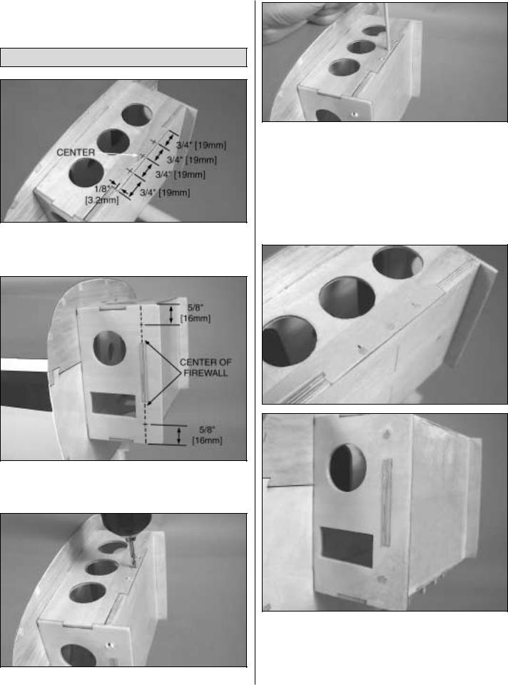
Once the glue has cured, install the servo tray in place as shown using 6-minute epoxy. The notched side fits against the former.
Engine Mounting Preparations
1. Top and bottom firewall support: Make marks 1/8" [3.2mm] away from the edge of the firewall at the center of the firewall support lip and 3/4" [19mm] to either side.
2. Firewall side supports: Make marks 5/8" [16mm] away from the edge of the firewall side supports’ flanges as shown in the photo above.
3. Drill 1/8" [3.2mm] holes 1" [25mm] deep at all the marks.
4. Mix some 30-minute epoxy. Wick some epoxy inside the holes drilled in the previous step. Insert a 1/8" [3.2mm] dowel inside a hole and slide it in and out several times to make sure that it is coated in epoxy. Push the dowel all the way in and cut it so that about 1/8" [3.2mm] of it protrudes. Repeat this step for all the holes. Clean up any excess glue with a paper towel dampened with denatured alcohol. Repeat this procedure for the bottom firewall.
5. Once the epoxy has cured, sand the dowels flush with the firewall supports.
6. Fuelproof the inside of the firewall and the sanded areas with epoxy mixed with alcohol. Let the epoxy cure.
12
 Loading...