


INSTRUCTION MANUAL
WARRANTY
Great Planes Model Manufacturing Co. guarantees this kit to be free from defects in both material and workmanship at the date of purchase. This warranty does not cover any component parts damaged by use or modification. In no case shall Great Planes' liability exceed the original cost of the purchased kit. Further, Great Planes reserves the right to change or modify this warranty without notice.
In that Great Planes has no control over the final assembly or material used for final assembly, no liability shall be assumed nor accepted for any damage resulting from the use by the user of the final user-assembled product. By the act of using the user-assembled product, the user accepts all resulting liability.
If the buyers are not prepared to accept the liability associated with the use of this product, they are advised to return this kit immediately in new and unused condition to the place of purchase.
READ THROUGH THIS INSTRUCTION MANUAL
FIRST. IT CONTAINS IMPORTANT INSTRUCTIONS
AND WARNINGS CONCERNING THE ASSEMBLY
AND USE OF THIS MODEL.
P.O. Box 788 |
Urbana, IL 61801 |
(217) 398-8970 |
CUB6P03 2/96 V1.1 |
Entire Contents © Copyright 1995 |

|
|
|
|
|
|
|
|
Exhaust outlet............................................................ |
|
42 |
|||
|
|
|
|
|
|
|
|
Dummy |
engine .......................................................... |
42 |
|||
|
|
|
|
|
|
|
|
Balance the airplane laterally .................................... |
43 |
||||
INTRODUCTION ............................................................... |
|
|
|
3 COVERING...................................................................... |
|
|
43 |
||||||
PRECAUTIONS................................................................. |
|
|
|
|
3 Covering |
notes |
.......................................................... |
43 |
|||||
DECISIONS YOU MUST MAKE........................................ |
3 |
Covering |
sequence ................................................... |
43 |
|||||||||
Engine and mount ....................................................... |
|
|
3 |
Painting |
..................................................................... |
|
|
44 |
|||||
Wing |
configuration...................................................... |
4 |
FINAL ASSEMBLY......................................................... |
44 |
|||||||||
PREPARATIONS.............................................................. |
|
|
|
4 Install |
the |
wheels....................................................... |
44 |
||||||
Accessories and additional items................................ |
4 |
Install |
the |
windows .................................................... |
44 |
||||||||
Building supplies and tools.......................................... |
4 |
Hinging |
...................................................................... |
|
|
45 |
|||||||
Common |
abbreviations ............................................... |
5 |
Balance |
your |
model................................................... |
45 |
|||||||
Types |
of |
wood ............................................................. |
|
|
5 |
Final radio installation and control hookup................ |
46 |
||||||
What |
about |
adhesives?............................................... |
5 |
Control |
surface |
throws .............................................. |
47 |
||||||
Die-cut patterns...................................................... |
|
|
6 &7 |
Apply |
decals and trim ................................................ |
48 |
|||||||
Get |
ready to build........................................................ |
|
9 |
FINAL HOOKUPS AND CHECKS .................................. |
48 |
||||||||
BUILD |
THE |
TAIL |
SURFACES........................................... |
9 |
Check |
for |
wing |
twist................................................... |
48 |
||||
Build |
the |
rudder........................................................... |
|
|
9 |
Balance the propeller ................................................ |
48 |
||||||
Build |
the |
fin................................................................ |
|
|
|
10 |
Pre-flight.................................................................... |
|
|
48 |
|||
Build the stabilizer ..................................................... |
|
|
10 |
Range |
|
check your radio ............................................ |
49 |
||||||
Build |
the |
elevators..................................................... |
|
10 |
Engine safety precautions ......................................... |
49 |
|||||||
Finish |
the |
tail |
surfaces............................................... |
11 |
AMA Safety Code |
...................................................... |
49 |
||||||
Hinge |
the |
tail |
surfaces............................................... |
12 |
FLYING............................................................................ |
|
|
|
|
50 |
|||
BUILD THE WING ........................................................... |
|
|
|
13 |
Find a safe place to fly .............................................. |
50 |
|||||||
Preparation................................................................ |
|
|
|
13 |
Takeoff....................................................................... |
|
|
|
50 |
||||
Build |
the |
wing |
tips |
..................................................... |
13 |
Flight.......................................................................... |
|
|
|
|
50 |
||
Build the wing |
panels ................................................ |
13 |
Landing...................................................................... |
|
|
|
51 |
||||||
Add the wing tips....................................................... |
|
|
16 |
TWO VIEW DRAWING ..................................... |
back cover |
||||||||
Install top and bottom LE sheeting ............................ |
19 |
|
|
|
|
|
|
||||||
Build the aileron servo hatch compartment............... |
21 |
|
|
|
|
|
|
||||||
Join |
the wing |
panels.................................................. |
22 |
|
|
|
|
|
|
||||
Complete the wing |
|
sheeting...................................... |
23 |
|
|
|
|
|
|
||||
Build |
the |
ailerons....................................................... |
|
|
24 |
|
|
|
|
|
|
||
Mount |
the |
aileron |
servos........................................... |
26 |
|
|
|
|
|
|
|||
Install |
the |
aileron |
linkage........................................... |
26 |
|
|
|
|
|
|
|||
BUILDTHE FUSELAGE ................................................ |
|
|
26 |
Your Great Planes Piper J-3 Cub 60 is not a toy, but |
|||||||||
Build |
the |
fuselage |
sides ............................................ |
26 rather a sophisticated, working model that functions very much |
|||||||||
Join |
the fuselage |
sides.............................................. |
28 |
like an actual airplane. |
|
|
|||||||
Sheet |
the |
fuselage |
deck............................................ |
31 |
Because of its realistic performance, the Cub 60, if not |
||||||||
Install |
the |
pushrod |
|
tubes ........................................... |
31 assembled and operated correctly, could possibly cause |
||||||||
Install |
the |
stabilizer |
base........................................... |
32 injury to yourself or spectators and damage property. |
|||||||||
Install the engine and mount ..................................... |
32 |
To make your R/C modeling experience totally |
|||||||||||
Install the fuel tank and throttle cable........................ |
33 enjoyable, we recommend that you get experienced, |
||||||||||||
Mount the landing gear ............................................. |
33 |
knowledgeable help with assembly and during your |
|||||||||||
Sheet the bottom of the fuselage .............................. |
34 first flights. You'll learn faster and avoid risking your model |
||||||||||||
Mount |
the wing .......................................................... |
|
|
34 before you're truly ready to solo. Your local hobby shop has |
|||||||||
Mount the stabilizer and fin ....................................... |
35 information about flying clubs in your area whose |
||||||||||||
Build |
|
the |
side |
stringers.............................................. |
36 |
membership includes qualified instructors. |
|
||||||
Add the tail fairing blocks .......................................... |
37 |
You can also contact the national Academy of Model |
|||||||||||
FINISHING...................................................................... |
|
|
|
|
37 Aeronautics (AMA), which has more than 2,300 chartered |
||||||||
Build |
|
the |
wing |
struts .................................................. |
37 clubs across the country. Through any one of them, |
||||||||
Fit the windshield and side windows ......................... |
39 |
instructor training programs and insured newcomer training |
|||||||||||
Assemble the cowl .................................................... |
|
|
39 |
are available. |
|
|
|
||||||
Final |
sanding............................................................. |
|
|
|
41 |
Contact the AMA at the address or toll-free phone |
|||||||
SCALE |
|
DETAILS............................................................. |
|
|
41 |
number below. |
|
|
|
||||
Landing gear struts.................................................... |
|
|
41 |
|
|
|
|
Academy of Model Aeronautics |
|||||
Gas cap..................................................................... |
|
|
|
|
41 |
|
|
|
|
5151 East Memorial Drive |
|||
Wire step ................................................................... |
|
|
|
|
41 |
|
|
|
|
Muncie, IN 47302-9252 |
|||
Propeller hub............................................................. |
|
|
|
41 |
|
|
|
|
Tele. (800) 435-9262 |
||||
Pilot |
and |
false |
floor.................................................... |
|
41 |
|
|
|
|
Fax (317) 741-0057 |
|||
2
Congratulations! Thank you for purchasing the Great Planes Piper J-3 CUB 60!
This J-3 CUB is a 1:4.7 scale model of the full-size version It's easy to build and fly, predictable, fairly aerobatic, and has no "bad habits" making it a great sport-scale airplane Although the model is sufficiently close to scale that it can place well in sport-scale competition, traditional Great Planes quality and ruggedness is evident throughout, making this an airplane you'll want to take along every time you go to the flying field Its 90" wingspan makes it International Miniature Aircraft Association* (IMAA) legal (as is the 83" clipped wing version).
*IMAA is an organization that promotes non-competitive flying of giant scale models.
IMAA
International Miniature Aircraft Association
205 S Hilldale Road
Salina, KS 67401
This is not a beginner's airplane! While the J-3 CUB is easy to build and flies great we must discourage you from selecting this kit as your first R/C airplane It lacks the self-recovery characteristics of a good basic trainer such as the Great Planes PT Series On the other hand if you have already learned the basics of R/C flying and you are able to safely handle a "trainer" airplane, the J-3 CUB is an excellent choice to improve your skills and learn new maneuvers
Please inspect all parts carefully before starting to build! If any parts are missing, broken or defective, or if you have any questions about building or flying this model, please call us at (217) 398-8970 and we'll be glad to help. If you are calling for replacement parts, please look up the part numbers and the kit identification number (stamped on the end of the carton) and have them ready when calling.
1 You must build the plane according to the plans and instructions. Do not alter or modify the model, as doing so may result in an unsafe or unflyable model In a few cases the plans and instructions may differ slightly from the photos In those instances you should assume the plans and written instructions are correct.
2. You must take time to build straight, true and strong
3You must use a proper R/C radio that is in first class condition, the correct sized engine and correct components (fuel tank, wheels, etc ) throughout your building process.
4You must properly install all R/C and other components so that the model operates properly on the ground and in the air.
5You must test the operation of the model before the first and each successive flight to insure that all equipment is operating and you must make certain that the model has remained structurally sound Be sure to check the nylon clevises often, and replace if they show signs of wear
6. You must fly the model only with the help of a competent, experienced R/C pilot if you are not already an experienced and knowledgeable R/C pilot at this time
NOTE We, as the kit manufacturer, can provide you with a top quality kit and great instructions but ultimately the quality of your finished model depends on how you build it, therefore, we cannot in any way guarantee the performance of your completed model, and no representations are expressed or implied as to the performance or safety of your completed model
Remember: Take your time and follow directions to end up with a well-built model that is straight and true.
3
D Four-channel radio with 5 servos
D "Y" Harness (Futaba J HCAM2500, Airtronics HCAM2520, JR HCAM2530)*
-or-
D Dual Servo Extension (Futaba J FUTM4130)
D 6" Servo extension cords (3) (Futaba J HCAM2000, Airtronics HCAM2020, JR HCAM2030)
D Propellers (see engine instructions for recommended size)
D 12 to 16 oz Fuel Tank (12 oz. GPMQ4105, 14 oz. GPMQ4106, 16 oz GPMQ4107)
D 1-1/2" Tail Wheel (GPMQ4243)
D 4" Cub Wheels (GPMQ4230 3-3/8" Piper Cub Wheels suitable)
D 3/16" Wheel Collars (4) (GPMQ4308, pkg of 4) D 3/32' Wheel Collars (2) (GPMQ4302, pkg of 4) D 3/16" Bolt on Axle Shafts (GPMQ4278)
D 25 foot roll model covering (Top Flite Cub Yellow MonoKote Covering TOPQ1220)
D 1/8" black striping tape (GPMQ1480)
D Medium silicone Fuel Tubing (GPMQ4131)
D 1/2" thick Latex Foam Rubber Padding (HCAQ1050) D Flexible Cable throttle pushrod (opt'l) (GPMQ3700) D Screw-Lock Pushrod Connectors (opt'l) (GPMQ3870) D Switch & Charge Jack Mount (optional) (GPMM1000) D Fuel filter (optional) (GPMQ4150)
D Fueling Valve (GPMQ4160)
DFuelproof paint (see "Painting" section of instructions on page 44)
D 3" scale pilot (optional) - (Williams Bros. WBRQ2626)
*ltems in parenthesis (GPMQ4130) are suggested part numbers recognized by distributors and hobby shops and are listed for your convenience Our own brand has been provided where possible GPM is the Great Planes brand, HCA is the Hobbico brand, TOP is Top Flite
D 2 oz Thin CA Adhesive - (GPMR6015)
D 2 oz Medium CA Adhesive - (GPMR6009) D 2 oz Thick CA Adhesive - (GPMR6003) D CA accelerator (optional) - (HCAR3750)
D CA applicator tips (optional) - (HCAR3780) D 6-Minute Epoxy - (GPMR6045)
D 30-Minute Epoxy - (GPMR6047)
D Pacer Z-560 (optional) - for gluing windscreen and side windows (PAAR3300)
D Silver Solder (recommended) - (GPMR8070 w/flux) D Hand or Electric Drill
D Drill Bits 1/16", 3/32", 7/64" or #35, 1/8", #29 or 9/64", 11/64", 3/16", #10 or 13/64", 7/32", 15/64", 17/64" and
1/4"
D Sealing Iron - (TOPR2100)
D Hot Sock (optional) - (TOPR2175)
D Heat Gun (optional) - (TOPR2000) D Razor Saw
D #1 knife handle - (XACR4305)
D #11 Blades - (XACR3121 pkg of 5) D Common pliers
D Screwdrivers (phillips and flat)
D T-Pins - (HCAR5100 small, HCAR5150 medium, HCAR5200 large)
D Straightedge - (Fourmost Non Slip FORR2149) D Masking Tape
D Sandpaper (coarse, medium, fine grit) D T-Bar or sanding block
D Waxed Paper
D Lightweight Balsa Filler - (HCAR3401) D 5/32" brass tube (optional)
D 1/8" brass tube (optional) D Tap Wrench
D 1/4-20 Tap - (GPMR8105 w/dnll bit) D 8-32 tap - (GPMR8103 w/dnll bit) D 6-32 tap - (GPMR8102 w/dnll bit) D IsopropyI Rubbing Alcohol (70%)
D Dremel Moto Tool or similar w/sanding drum, cutting burr (optional)
D 9/64" ball end hex wrench - (GPMR8004)
D Kyosho" Curved Scissors (optional) - (KYOR1010)
4
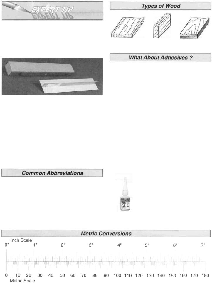
On our workbench, we have four 11" T-Bar sanders, equipped with #50, #80, #150 and #220-grit sandpaper. This setup is all that is required for almost any sanding task. Custom sanding blocks can be made from balsa for sanding hard to reach spots. We also keep some #320-grit wet-or-dry sandpaper handy for finish sanding before covering.
Balsa Basswood Plywood
T-Bar sanding tools are made from lightweight extruded aluminum and can be found at most hobby shops. A 2" x 11" strip of sandpaper is attached to the T-Bar by gluing it on with rubber cement. Apply the rubber cement to both the bottom of the T-Bar and the back of the sandpaper. When both surfaces are dry, press the sandpaper firmly onto the T-Bar. Spray adhesive can be used for this purpose but it's harder to remove the sandpaper when you need to replace it.
Wooden sanding blocks can be made from 11" lengths of 1" x 2" scrap lumber. Start on one side, then wrap a sheet of sandpaper completely around the wood, ending on the same side as the one you started on. Push 3 or 4 thumbtacks into this edge, then trim off the excess material.
Elev = Elevator
Fuse = Fuselage
LE = Leading Edge (front)
LG = Landing Gear
Lt = Left
Ply = Plywood
Rt = Right
Stab = Stabilizer
TE = Trailing Edge (rear)
" = Inches
We understand that the caliber of modelers likely to build the Great Planes Cub 60 may be rather high. You may already know all about the types of adhesives you like to use. However, due to its stability and easy building features, many first time or second time builders may try their hand at the Great Planes Cub 60. For those modelers (experts may read along), we have provided some explanation about the variety of adhesives used during construction of a model.
Cyanoacrylate or CA glue has changed the way models are built more than any other advance in modeling technology. In the good ol' days, model cement like Ambroid, Duco, Comet and Sigment were the glues of choice. They all had a strong odor that could cause dizziness, dried slowly (compared to CA) and became brittle with age. CA, on the other hand, is stronger, works almost instantly and is bottled in three different viscosities (thicknesses). CA is used for most glue joints, except where epoxy is specified. CA does emit rather strong fumes (some say it's like tear gas) as it cures, so rule number one is to work in a well ventilated area. All CA glues work best if the joints are smooth and fit well.
Thin CA is also known simply as CA. This is the adhesive that has revolutionized model building because it allows you to assemble the parts first, then apply the adhesive. The thin formulation flows or "wicks" into the joints and sets almost instantly, eliminating the need to hold things together while the glue dries. You
will often use Thin CA for the initial bond, then follow with medium or thick CA for extra strength, especially when gluing plywood or hardwood. (Continued on page 8)
5

DIE-CUT PATTERNS
6
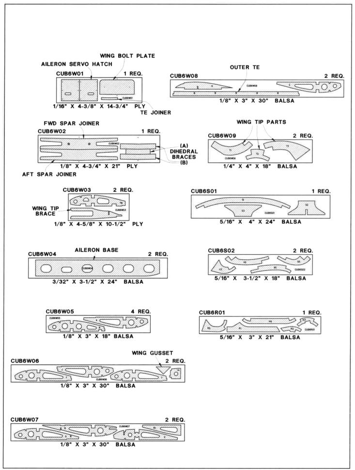
DIE-CUT PATTERNS
7
CA+ is also known as medium or gap filling CA CA+ is used for surface gluing, filling small gaps between poorly matched parts and for general purpose applications It cures slower than thin CA, allowing you to apply a bead to two or three parts before assembly Curing time without accelerator is 20-30 seconds
CA- or thick CA is used when extra positioning time is needed CAis a great gap filler and is also used to make fillets when a little extra strength is required. Curing time is about 1-2 minutes.
Accelerator is a liquid chemical that comes in a spray bottle for use in speeding up the cure time of all CA types It should be misted on, not sprayed heavily on the joint Accelerator may cause exposed CA to bubble and sometimes change color. If accelerator is sprayed on too heavily it may weaken the glue joint, so use it sparingly
hold-down blocks As with most epoxies you mix equal parts of resin and hardener, stir well, then apply a thin film to each part Parts should be clamped, pinned, taped or weighted in place until fully cured Before the epoxy cures, clean off any excess with a paper towel A word of caution about mixing epoxy-don't use extra hardener in the hopes of making the mixture harder or work faster Just about all epoxies work best with exactly a 50/50 mix When you increase the amount of hardener you run the risk of causing the cured epoxy to become either brittle or rubbery-neither being as strong as a properly mixed batch.
6-Minute epoxy is used for simple, small gluing a p p l i c a t i o n s - w h e r e elaborate alignment is not equired Working time (before it's too gooey to use) is about 5 minutes, handling time 15 minutes and it's fully cured in about 1 hour.
30-minute epoxy is used for extra strength (because it can penetrate longer) and where several parts must e aligned and checked before it cures Working time is about 25 minutes, handling time 2 hours, and
it's fully cured in 8 hours
Epoxy
Great Planes has two epoxy formulations available for the modeler Both offer exceptional strength and convenient working times Use epoxy when the joint requires exceptional strength, such as when installing the firewall, when joining the wing panels, and when installing wing
Great Planes Pro" Wood Glue is an Aliphatic resin glue that works well on all types of wood It is non-toxic, virtually odorless and dries clear Some people are sensitive to CA and epoxy fumes, so this is a good alternative for general modeling use Its only drawback is that it is slow to cure, requiring the parts to be securely clamped, pinned or taped while the glue dries
Okay, you've got your work space ready your tools are at hand, and you know how to choose and use the right glue for the job Let's get started!
8
D 1 Unroll the plan sheets Reroll the plan inside out to make them lie flat
Before beginning construction of each individual tail surface tape waxed paper over the drawing when it is
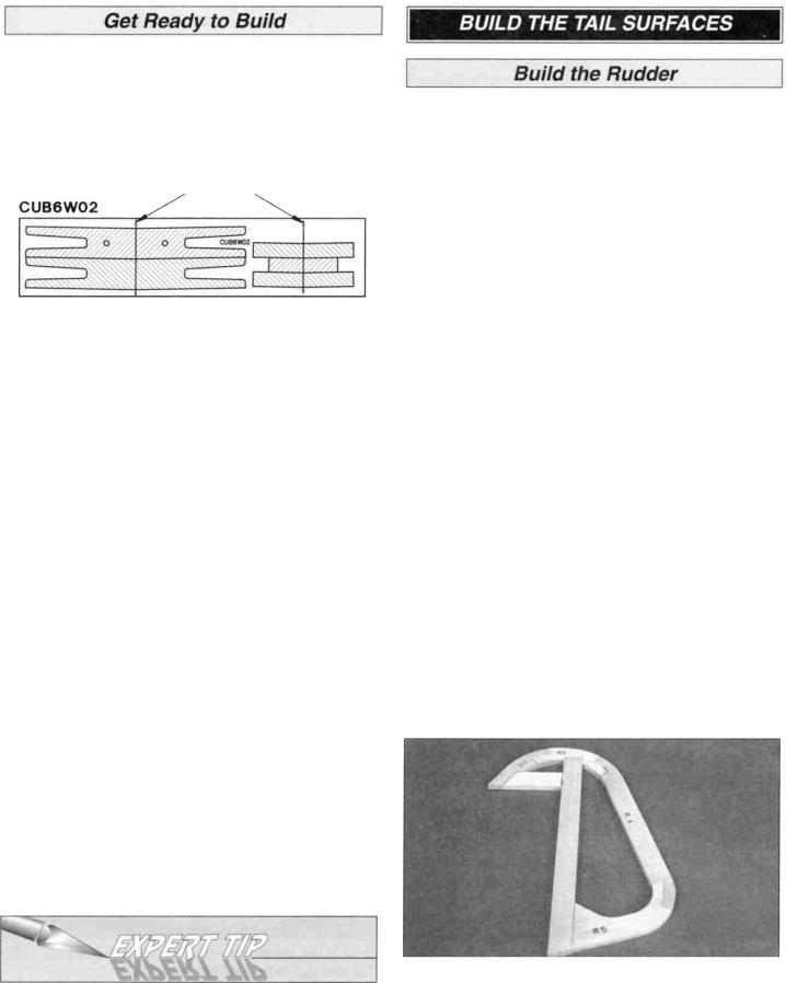
time to build that piece Begin with the rudder
MARK
CENTERLINES
D 1 Place the die-cut 5/16" balsa rudder parts R2, R3, R4 and R5 over the plan in their locations Check each joint for a good fit and make adjustments if necessary Pin the parts to the building board but do not use glue at this time.
D 2 Locate the die-cut 1/16" plywood sheet W01 and the die-cut 1/8" plywood sheet W02 Draw centerlines on the dihedral braces, wing joiners and wing bolt plate by connecting the punch marks.
D 3 Remove all parts from the box As you do, determine the name of each part by comparing it with the plan and the parts list included with this kit Using a ball point pen, lightly write the part name or size on each piece to avoid confusion later Use the die-cut patterns shown on pages 7 and 8 to identify the die-cut parts and mark them before removing them from the sheet Save all scraps If any of the die-cut parts are difficult to punch out do not force them' Instead, cut around the parts with a hobby knife After punching out the die-cut parts, use your T-Bar sander or sanding block to lightly sand the edges to remove any die-cutting irregularities
D 4 As you identify and mark the parts, separate them into groups, such as fuse (fuselage), wing, fin, stab (stabilizer) and hardware.
Zipper-top food storage bags are handy to store your parts as you sort, identify and separate them into sub-assemblies
NOTE: The purpose for checking each joint for a good fit is to be sure the finished shape of the assembly matches that of the drawing on the plan Every joint may not be an exact fit due to the technical nature of die-cutting such thick wood (5/16") If you're a very discriminating builder, you are likely to spend a few extra moments perfecting the fit of each and every joint before reaching for the CA Simply filling in the small gap where noticeable with thick CA is an alternate method to custom fitting each part and will yield a secure, strong glue joint
D 2 Select the straightest piece of 5/16" x 7/8" x 24" balsa stick Set this piece aside for use later on the stabilizer trailing edge
D 3 Cut the rudder leading edge from another 5/16" x 7/8" x 24" balsa stick Check for a good fit, then pin the LE to the building board over its location Cut the horizontal frame section from the remaining piece of balsa and pin into position
D 4 Remove the parts from the plan, then one at a time, pin each piece back into position using thick CA to securely glue the parts together Wipe away excess glue with a paper towel before it cures - sanding will be easier later
9
D 5 Cut the ribs from the 5/16" x 5/16" x 30" balsa stick. Position the ribs in the rudder frame and securely glue them in place with thick CA.
D 6 Remove the rudder from the building board and inspect all the glue joints Add thin CA to all the tight-fitting joints and thick CA to any open joints Large gaps may be filled with balsa dust and thin CA.
D 1. Locate the die-cut 5/16" balsa fin leading edge R1 and pin it in place on the plan.
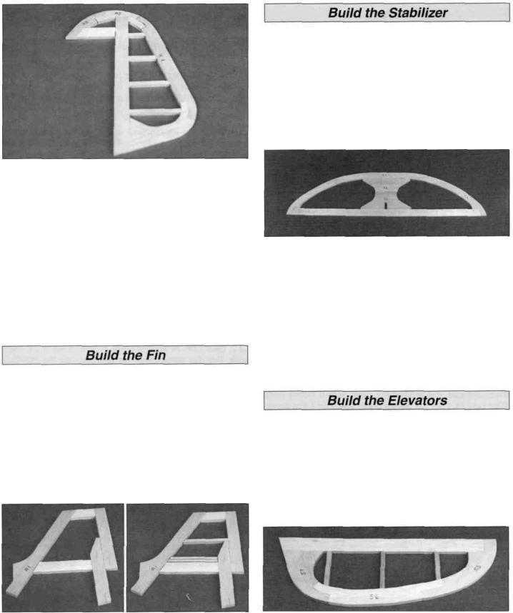
D 1. Securely glue the die-cut 5/16" balsa stabilizer parts S2 and S3 together over the plan.
D 2 Position S1 and the two S4's over their locations on the plan Check the fit of the joints, make adjustments if necessary, then pin them in place.
D 3. Cut the stabilizer trailing edge from a 5/16" x 7/8" balsa stick. Fit the trailing edge between the S4's.
D 4 When satisfied with all joints, remove the assembly from the building board Reinstall each part on the building board with pins, gluing them together with thick CA as you proceed.
D 5. Cut the ribs from the 5/16" x 5/16" x 24" balsa stick and glue them in place with thick CA.
D 6 Remove the stabilizer from the building board and inspect all the glue joints. Apply thick or thin CA where necessary.
D 2. Cut the fin top, fin base, and the inner and outer fin trailing edges from the remaining 5/16" x 7/8" balsa strip Pin the parts in place and make sure all the joints fit well. Remove the parts and securely glue each joint with thick CA as you pin them back into position.
D 3 Cut the ribs from the remaining 5/16" x 5/16" balsa stick. Glue them in place with thick CA.
D 4. Remove the Fin from the building board and inspect all the glue joints Apply thick or thin CA where necessary.
D D 1. Pin the die-cut 5/16" balsa elevator parts S5, S6 and S7 on the plan, making adjustments for any poor-fitting glue joints.
D D 2 Cut the elevator leading edge from a 5/16" x 7/8" balsa strip Fit the LE in place on the plan and pin it in place Glue all of the joints with thick CA, in the same manner as described previously.
D D 3. Cut the elevator ribs from the 5/16" x 5/16" balsa stick and glue in position with thick CA.
D D 4. Remove the elevator from the building board and inspect all the glue joints. Add CA where necessary Build the other elevator.
10
D 1. Carefully sand all the tail surfaces flat with 150-grit sandpaper and a large sanding block or T-bar. Remove as little material as possible and don't get carried away - inspect your work as you proceed. It's easy to sand a low spot into the ribs or trailing edges.
D 2. Centerlines must be drawn where the hinges are to be inserted. Start with an elevator. A Bic ball point pen lines up with the center of the 5/16" thick balsa (double check this - the height may vary due to the extent of your sanding or different pens. Adjust the height of the pen or the elevator as necessary to draw a centered line). Lay the elevator and the pen on a flat table and draw a line on the edge. Draw centerlines on the leading edges of the rudder and elevators, and on the trailing edges of the stabilizer and fin.
D 3. From the bottom of the rudder measure 1-5/8" along the leading edge. Then drill a 7/64" hole, 3/4" deep, where the tail wheel wire fits into the rudder.
D 4. Groove the rudder to clear the hinge bearing. A sharpened piece of 5/32" brass tubing works well as a tool to cut the groove.
D 5. Trial fit the tail gear wire in the rudder. Make adjustments if necessary.
D 6. Position the elevators on the plan and center the elevator joiner wire over the elevators. Transfer the location of the joiner wire to the elevators. Make the marks lightly so they may be sanded off easily.
D 7. Accurately drill a 9/64" (or #29) hole into each elevator leading edge approximately 1" deep. The hole must be perpendicular to the elevator leading edge.
0 8. Cut a groove in the leading edge of the elevators to accept the elevator joiner wire. A sharpened piece of 1/8" brass tube works well to cut the groove just as you did the rudder.
D 9. Test fit (do not glue yet) the joiner in the elevators. With the joiner inserted, the elevators must lie flat and the leading edges must line up with a straightedge. If the elevators both don't lie flat on a table top, you may make slight adjustments by carefully twisting the joiner wire. If the leading edges don't match up with a straight edge, you may slightly enlarge the holes drilled into the elevator leading edges to allow slight repositioning.
11
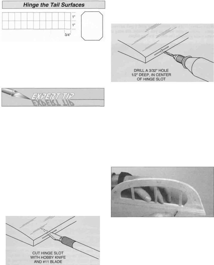
D 1 Cut the hinges from the supplied 2" x 9" composite hinge material You will need six hinges for the elevator and three for the rudder Store the remaining hinges for use later during construction.
D 2 Use the plan as a guide to lightly mark the locations of the hinges Refer to the Expert Tip that follows, then cut matching hinge slots in all four parts.
Expert tip for using CA hinges
The hinge material supplied in this kit consists of a 3-layer lamination of mylar and polyester It is specially made for the purpose of hinging model airplane control surfaces Properly installed, this type of hinge provides the best combination of strength, durability and ease of installation We trust even our best show models to these hinges, but it is essential to install them correctly
Please follow the instructions carefully to obtain the best results These instructions may be used to effectively install any of the various brands of CA hinges.
The most common mistake made by modelers when permanently installing this type of hinge is not applying a sufficient amount of glue to fully secure the hinge over its entire surface area, or, the hinge slots are very tight, restricting the flow of CA to the back of the hinges This results in hinges that are only "tack glued" approximately 1/8" to 1/4" into the hinge slots The following technique has been developed to help ensure thorough and secure gluing.
A. Cut the hinge slot using a #11 blade in a standard #1 knife handle The CA hinges provided have a thickness that fits this type of slot very well Trial fit the hinge into
the slot If the hinge does not slide in easily, work the knife blade back and forth in the slot a few times to provide more clearance (it is really the back edge of the blade that does the work here in widening the slot).
BDrill a 3/32" hole, 1/2" deep, in the center of the hinge slot. If you use a Dremel Moto-TooF for this task, it will result in a cleaner hole than if you use a slower speed power or hand drill Drilling the hole will twist some of the wood fibers into the slot, making it difficult to insert the hinge so you should reinsert the knife blade, working it back and forth a few times to clean out the slot.
CTrial fit the hinges into the slots and, without using any glue, temporarily attach the control surface, to verify the fit.
STOP! DO NOT GLUE THE HINGES IN PLACE UNTIL AFTER THE MODEL IS COVERED!
D 3 Bevel the leading edges of the elevator and rudder Draw the "bevel to" lines on the leading edges of the elevators and the rudder Refer to the plan for the correct angle.
D 4. Carve or sand the bevel on the leading edges of the rudder and elevators A razor plane allows you to rough-in the bevel before finishing with a sanding block
D 5 Reinstall the hinges and test fit the operation of the rudder and the elevators Make adjustments in the hinge slots if necessary Now would be a good time to designate a top and bottom of the elevators and stabilizer - just in case one side looks a little better than the other
12
D 6 Sand the leading edges of the stabilizer, fin and the trailing edges of the rudder and elevators to a rounded shape, as shown in the cross-sections on the plan.
D 7. Sand the elevator joiner with 150-grit sandpaper for good glue adhesion then liberally pack the holes in the elevators with 30-minute epoxy Insert the joiner and wipe away epoxy before it cures.
IMPORTANT: For an airplane to fly well with no unexpected tendencies, all good modelers understand that each assembly - especially the wing - must be built on a flat surface This is important advice for new builders Also, a relatively soft, flat building board that you can stick "T" pins into is required. This is for pinning down individual parts that make up the completed assembly A suitable building board is a sheet of ceiling tile or "Celotex" used in home construction This material may be found at hardware or home improvement stores. If the building board is not flat, it must be clamped to your flat building table. Now we're ready to begin!
NOTE: The plan shows the two different wing types which may be built from this kit. You may choose the standard wing or the clipped wing version Generally, the clipped wing will be more aerobatic than the standard wing If you decide to build the clipped wing, cut the plan on the dashed line between the two R4 ribs Overlap the plan towards the center of the wing and match the registration marks as indicated. Keep the plan straight, then tape it together when you have the registration marks aligned Check the alignment with a straightedge. No change is necessary for the standard wing.
NOTE: One R4 rib is eliminated from each wing panel if building the clipped wing.
Build one wing "half or panel at a time. You may cut each wing panel from the plan sheet to place on your building board. Tape the right wing plan to your flat work surface, and cover it with waxed paper.
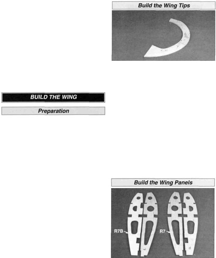
D D 1. Place the die-cut 1/4" balsa wing tip parts T1, T2 and T3 over the plan and check all joints for proper fit. Make adjustments if necessary Pin the parts over the plan, gluing with thick CA as you proceed.
D D 2 Remove the wing tip from the building board and inspect all the glue joints Add thin CA to all tight joints and thick CA to all open joints.
D D 3 Place the wing tip on your work surface and lightly sand both sides flat and smooth with a sanding block and 150-grit sandpaper.
D 4. Return to step 1 and build the other wing tip.
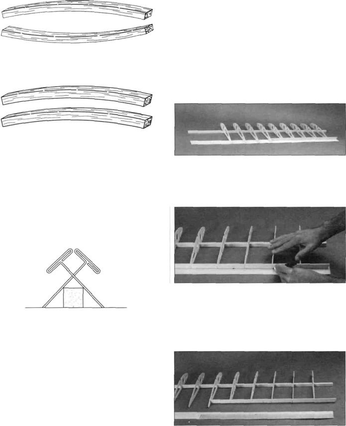
D 1 Carefully punch out all the die-cut 1/8" balsa R2 through R8 wing ribs and the die-cut 1/8" plywood rib doublers R7B Sand the edges slightly to remove any die-cutting irregularities. Use thick CA to laminate the
R7Bs to ribs R7. Don't forget to make a RIGHT and a LEFT.
13
TWO WARPED SPARS INSTALLED
THIS WAY WILL RESULT IN A
STRAIGHT WING
TWO WARPED SPARS INSTALLED
THIS WAY WILL RESULT IN A
WARPED WING
D D 2 Locate all four 1/2" x 1/2" x 40" basswood spars. Examine them carefully for possible imperfections Look for knots, soft spots, diagonal grain and any other imperfections If possible, position each spar so the imperfections are on the outer half of the wing panel (toward the tip) where they will be least affected by high stress If the spars are warped slightly, try to "balance them out by installing the warped spars in opposite directions (see sketch).
D D 3. Do not use any glue until step 15. For now, we're just making preparations and familiarizing ourselves with the layout Place one of the 1/2" x 1/2" x 40" basswood spars on the wing plan and pin the spar down with crossed T-pins as shown in the sketch We recommend crossed T-pins at every rib bay (the space between the ribs) NOTE: Align the end of the spar with the outboard edge of wing rib R8 at the wing tip.
D D 4. Locate a 3/32" x 2" x 40" balsa trailing edge sheet. It is supplied slightly wide so you may trim it to straighten any bowed edges Using a straightedge, trim the piece to 1-29/32". Set the trailing edge sheet aside for now.
D D 5. Without gluing, place ribs R3 through R7 and the laminated R7/R7B (but not R2 or R8) on the spar in their locations as shown on the plan If building the clipped wing version, discard one of the R4 ribs.
NOTE: Rib 3 does not contact the plan since the center section will be sheeted later.
D D 6 Slide the trailing edge sheet against the notches in the bottom of the ribs The outer tip of the sheet should match the plan and the "overhang" should be at the center section.
D D 7 Position the die-cut 1/8" |
balsa outer trailing edge |
at the rear of ribs R5 through R7. |
|
D D 8 Mark a line on the trailing edge sheet against the entire length of the outside of the outer trailing edge and rib R5 As you mark the line, make sure all ribs and the outer trailing edge are lying flat on the sheet.
D D 9. Remove the sheet and use a straightedge and knife to cut along the line. Save the scrap piece.
14
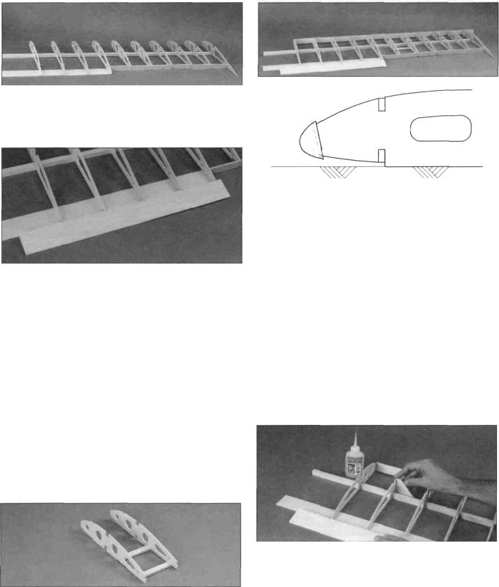
D D 10 Slide the finished trailing edge sheet into position. Don't reach for the glue yet Add rib R8.
D D 14 Match the notches in the 42" shaped balsa leading edge with the plan Add the leading edge to the ribs (still no glue) making sure each rib is fitted into its respective notch Center the leading edge so there is an equal amount of space above and below each rib Cut the leading edge flush with rib R2.
D D 11 Locate the tapered balsa inner trailing edge If you are building the clipped wing version, be sure the rib notches line up with the rib locations on the plan before cutting. Pin the inner trailing edge in position with the ribs in the notches, then cut the outboard tip of the inner trailing edge flush with the outboard edge of rib R5.
D D 12. Fit the ribs into the notches on the inner trailing edge, then push it as far forward as it will go until the ribs are fully seated Pull the sheet back until it is tight against the trailing edge Pin the inner trailing edge and the trailing edge sheet to the plan Install rib R2.
NOTE: Rib 2 will not contact the plan since the center section will be sheeted later.
D D 13 Cut the 1/4" x 1/2" x 18" balsa aileron servo rail stick into four pieces, 3-3/4" each Remove both R6 ribs Install both servo rails Refer to the cross-section drawing - be sure both servo rails are fully seated into their notches The ends of the servo rails must be flush with the ribs Reinstall the assembly over the spar and into the outer trailing edge (I promise we'll be gluing soon).
Double check your work Make sure all ribs are contacting the trailing edge sheet and fit all the way onto the basswood spar. Confirm that each rib meets the spar exactly at its intended location over the plan After all the fitting and Jiggling of parts, now is the time to be sure the spar is still securely pinned to your flat building board. Repin or add more pins if necessary
Let's start gluing!
D D 15 Beginning with rib R3, use the die-cut 1/8" plywood 90 degree triangle (indicated as "90") to make sure the rib is vertical while you add a few drops of thin CA where the rib meets the spar Don't glue rib R2 to the spar until instructed to do so. Be sure the bottom rear of each rib is contacting the trailing edge sheet Don't add too much CA - we're just "tack gluing" now Add a few drops of CA to R2 where it contacts the trailing edge sheet Glue the remaining ribs to the spar and trailing edge sheet (don't glue R2 to the main spar) making sure each rib is vertical and contacting the trailing edge sheeting.
15
D D 16. Wick thin CA along the joint where the outer trailing edge contacts the sheet and also to each rib. Glue both servo rails to the R6 ribs and glue the aft servo rail to the sheeting. Wick thin CA into the notches in the inner trailing edge at each rib and glue the inner trailing edge to the trailing edge sheet.
D D 17. Confirm that the leading edge is still centered and each rib is tightly fitted into the notches. Refer to the sketch at step 14 to see how the leading edge matches the ribs; the leading edge is tilted downward somewhat. Wick thin CA into each joint.
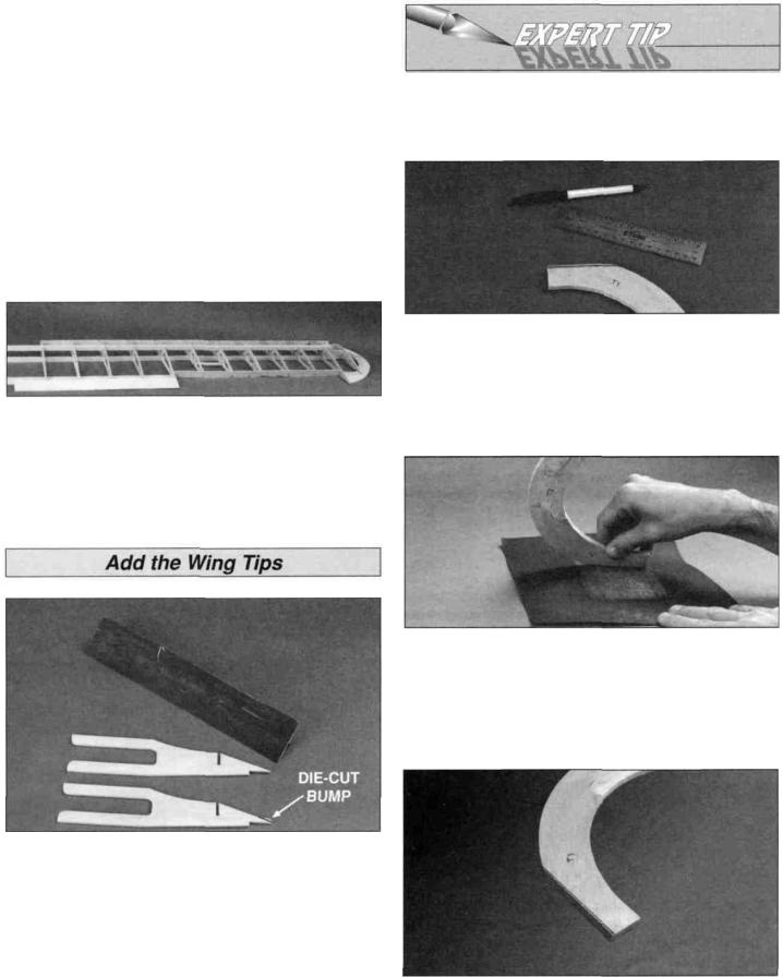
HOW TO MAKE A BEVEL
The following process will help you create a bevel that is right the first time.
D D 18. Install the top 1/2" x 1/2" x 40" basswood spar. Confirm that the top of the spar is flush with the top of each rib and make sure the ribs are vertical (90°). The outer tip of the spar should be flush with rib R8, just like the bottom spar. Glue the spar in place with thin CA.
D D 1. Locate the die-cut 1/8" plywood wing tip brace, the die-cut 1/8" balsa wing tip rib R9 and your previously assembled outer wing tip. Sand off the "die-cut bump" from the wing tip brace.
A) First, you need a fresh, full sheet of 220-grit sandpaper. Draw the bevel lines and reference lines on the part. The bevel lines are the lines that you sand to. The reference lines are lines slightly over the size of the bevel that you use as a reference in order to keep the bevel parallel.
B) Sand to the bevel lines. The method of sanding is important. Sand only in one direction - usually "dragging" the part is best as it keeps it from "chattering" and creating the unwanted rounded bevel. It helps to imagine the angle of the bevel required as you begin to sand. Just take a little off at a time and mind your border lines.
D D 2. Fit the wing tip rib R9 into the plywood wing tip brace and slide the assembly into the ribs along the spars. Slide the previously prepared outer wing tip into position. Refer to the following Expert Tip to bevel the leading edge of the wing tip.
C) After careful sanding and frequently inspecting your work as you go, you will have a sharp, accurate bevel. The bevel is parallel to the reference lines.
16
 Loading...