


Radio: |
5-chan nel mini mum |
Engine: |
1.8 - 2 cu in [30 - 35cc] two-stro ke gasoline engine |
WARRANTY
Great Planes ® Model Manufacturing Co. guarantees this kit to be free from defects in both material and workmanship at the date of purchase. This warranty does not cover any component parts damaged by use or modification. In no case shall Great
Planes’ liability exceed the original cost of the purchased kit.
Further, Great Planes reserves the right to change or modify this warranty without notice.
In that Great Planes has no control over the final assembly or material used for final assembly, no liability shall be assumed nor accepted for any damage resulting from the use by the user of the final user-assembled product. By the act of using the user-assembled product, the user accepts all resulting liability.
If the buyer is not prepared to accept the liability associated with the use of this product, the buyer is advised to return
this kit immediately in new and unused condition to the place of purchase.
To make a warranty claim send the defective part or item to Hobby Services at the address below:
Hobby Services
3002 N. Apollo Dr. Suite 1
Champaign IL 61822 USA
Include a letter stating your name, return shipping address, as much contact information as possible (daytime telephone number, fax number, e-mail address), a detailed description of the problem and a photocopy of the purchase receipt. Upon receipt of the package the problem will be evaluated as quickly as possible.
READ THROUGH THIS MANUAL BEFORE STARTING CONSTRUCTION. IT CONTAINS IMPORTANT INSTRUCTIONS AND WARNINGS CONCERNING THE ASSEMBLY AND USE OF THIS MODEL.
Champaign, Illinois
(217) 398-8970, Ext 5 airsupport@greatplanes.com
© 2014 Great Planes Model Mfg. A subsidiary of Hobbico, Inc. |
GPMA1435 |
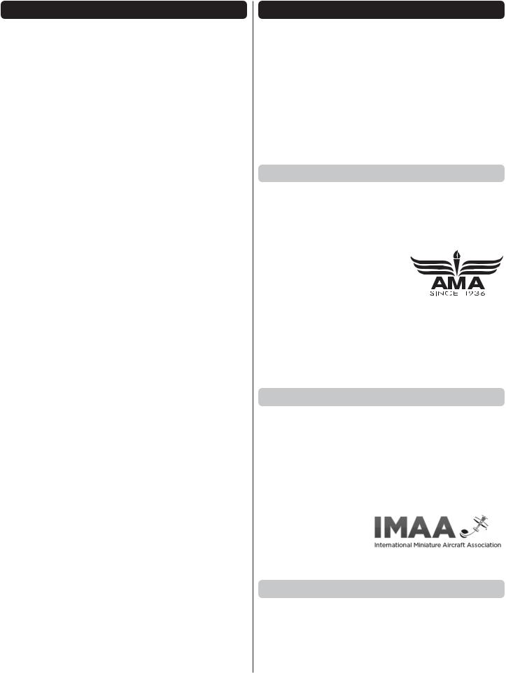
TABLE OF CONTENTS
INTRODUCTION . . . . . . . . . . . . . . . . . . . . . . . . . . . . . . . . 2
SAFETY PRECAUTIONS . . . . . . . . . . . . . . . . . . . . . . . . . 3
DECISIONS YOU MUST MAKE . . . . . . . . . . . . . . . . . . . . 3
Radio Equipment . . . . . . . . . . . . . . . . . . . . . . . . . . . . . 3
Engine Recommendations. . . . . . . . . . . . . . . . . . . . . . 4
Motor Recommendations. . . . . . . . . . . . . . . . . . . . . . . 4
Pilot . . . . . . . . . . . . . . . . . . . . . . . . . . . . . . . . . . . . . . . 4
ADDITIONAL ITEMS REQUIRED. . . . . . . . . . . . . . . . . . . 4
Required Hardware and Accessories . . . . . . . . . . . . . 4
Optional Supplies and Tools . . . . . . . . . . . . . . . . . . . . 4
IMPORTANT BUILDING NOTES . . . . . . . . . . . . . . . . . . . 4
KIT INSPECTION . . . . . . . . . . . . . . . . . . . . . . . . . . . . . . . 5
ORDERING REPLACEMENT PARTS . . . . . . . . . . . . . . . 5
KIT CONTENTS. . . . . . . . . . . . . . . . . . . . . . . . . . . . . . . . . 5
PREPARATIONS . . . . . . . . . . . . . . . . . . . . . . . . . . . . . . . . 6
ASSEMBLE THE WING . . . . . . . . . . . . . . . . . . . . . . . . . . 6
ASSEMBLE THE FUSELAGE . . . . . . . . . . . . . . . . . . . . . 9
Install the Stabilizer and Rudder . . . . . . . . . . . . . . . . 10
Install the Elevator and Rudder Servos . . . . . . . . . . . 12
Mount the Tail Wheel, Bracket and Support Wires . . 14
ELECTRIC MOTOR INSTALLATION . . . . . . . . . . . . . . . 16
INSTALL THE ENGINE, THROTTLE/CHOKE
SERVOS AND IGNITION SWITCH . . . . . . . . . . . . . . . 19
INSTALL THE COWL . . . . . . . . . . . . . . . . . . . . . . . . . . . 25
INSTALL THE WHEELS, WHEEL PANTS
AND WING STRUTS . . . . . . . . . . . . . . . . . . . . . . . . . . 28
COMPLETE THE RADIO INSTALLATION . . . . . . . . . . . 31
INSTALL THE COCKPIT, PILOT AND SPINNER . . . . . 32
APPLY THE DECALS . . . . . . . . . . . . . . . . . . . . . . . . . . . 36
GET THE MODEL READY TO FLY. . . . . . . . . . . . . . . . . 36
Check the Control Directions. . . . . . . . . . . . . . . . . . . 36
Set the Control Throws . . . . . . . . . . . . . . . . . . . . . . . 36
Balance the Model (C.G.) . . . . . . . . . . . . . . . . . . . . . 37
Balance the Model Laterally . . . . . . . . . . . . . . . . . . . 38
PREFLIGHT . . . . . . . . . . . . . . . . . . . . . . . . . . . . . . . . . . . 38
Identify Your Model . . . . . . . . . . . . . . . . . . . . . . . . . . 38
Charge the Batteries . . . . . . . . . . . . . . . . . . . . . . . . . 38
Balance Propellers. . . . . . . . . . . . . . . . . . . . . . . . . . . 38
Ground Check and Range Check . . . . . . . . . . . . . . . 38
ENGINE SAFETY PRECAUTIONS. . . . . . . . . . . . . . . . . 39
AMA SAFETY CODE. . . . . . . . . . . . . . . . . . . . . . . . . . . . 39
CHECK LIST . . . . . . . . . . . . . . . . . . . . . . . . . . . . . . . . . . 39
FLYING . . . . . . . . . . . . . . . . . . . . . . . . . . . . . . . . . . . . . . 40
Fuel Mixture Adjustments . . . . . . . . . . . . . . . . . . . . . 40
Takeoff . . . . . . . . . . . . . . . . . . . . . . . . . . . . . . . . . . . . 40
Flight . . . . . . . . . . . . . . . . . . . . . . . . . . . . . . . . . . . . . 41
Landing . . . . . . . . . . . . . . . . . . . . . . . . . . . . . . . . . . . 41
FIREWALL TEMPLATES . . . . . . . . . . . . . . . . . . . . . . . . 43
INTRODUCTION
Great Planes is very proud to bring you the Citabria. This is a great flying model that you will enjoy and will turn heads at the flying field. We have made a realistic airplane that has no bad flight characteristics. We believe you will be very pleased with the final product.
For the latest technical updates or manual corrections to the Giant Scale Citabria ARF visit the Great Planes web site at www.greatplanes.com. Open the “Airplanes” link, then select the Giant Scale Citabria ARF. If there is new technical information or changes to this model a “tech notice” box will appear in the upper left corner of the page.
AMA
If you are not already a member of the AMA, please join! The AMA is the governing body of model aviation and membership provides liability insurance coverage, protects modelers’ rights and interests and is required to fly at most R/C sites:
Academy of Model Aeronautics
5151 East Memorial Drive
Muncie, IN 47302-9252
Tele. (800) 435-9262
Fax (765) 741-0057
Or via the Internet at: http://www.modelaircraft.org
IMPORTANT!!! Two of the most important things you can do to preserve the radio controlled aircraft hobby are to avoid flying near full-scale aircraft and avoid flying near or over groups of people.
IMAA
The Great Planes Giant Scale Citabria ARF is an excellent sport-scale model and is eligible to fly in IMAA events. The IMAA (International Miniature Aircraft Association) is an organization that promotes non-competitive flying of giantscale models. If you plan to attend an IMAA event, obtain a copy of the IMAA Safety Code by contacting the IMAA at the address or telephone number below, or by logging on to their web site at:
IMAA
205 S. Hilldale Road
Salina, KS 67401
Tele. (913) 823-5569
www.fly-imaa.org/imaa/sanction.html
Scale Competition
Though the Great Planes Citabria is an ARF and may not have the same level of detail as an “all-out” scratch-built competition model, it is a scale model nonetheless and is therefore eligible to compete in the Fun Scale class in AMA competition (we receive many favorable reports of Great Planes ARFs in scale competition!). In Fun Scale, the “builder
2

of the model” rule does not apply. To receive the five points for scale documentation, the only proof required that a full size aircraft of this type in this paint/markings scheme did exist is a single sheet such as a kit box cover from a plastic model, a photo, or a profile painting, etc. If the photo is in black and white other written documentation of color must be provided. Contact the AMA for a rule book with full details.
If you would like photos of the full-size Citabria for scale documentation, or if you would like to study the photos to add more scale details, photo packs are available from:
Bob’s Aircraft Documentation |
Tele: (714) 979-8058 |
3114 Yukon Ave |
Fax: (714) 979-7279 |
Costa Mesa, CA 92626 |
bobsairdoc.com |
SAFETY PRECAUTIONS
Protect Your Model, Yourself & Others… Follow These Important Safety Precautions
1. Your Citabria should not be considered a toy, but rather a sophisticated, working model that functions very much like a full-size airplane. Because of its performance capabilities, the Citabria, if not assembled and operated correctly, could possibly cause injury to yourself or spectators and damage to property.
2.You must assemble the model according to the instructions. Do not alter or modify the model, as doing so may result in an unsafe or unflyable model. In a few cases the instructions may differ slightly from the photos. In those instances the written instructions should be considered as correct.
3.You must take time to build straight, true and strong.
4.You must use an R/C radio system that is in good condition, a correctly sized engine, and other components as specified in this instruction manual. All components must be correctly installed so that the model operates correctly on the ground and in the air. You must check the operation of the model and all components before every flight.
5.If you are not an experienced pilot or have not flown this type of model before, we recommend that you get the assistance of an experienced pilot in your R/C club for your first flights. If you’re not a member of a club, your local hobby shop has information about clubs in your area whose membership includes experienced pilots.
6.While this kit has been flight tested to exceed normal use, if the plane will be used for extremely high stress flying, such as racing, or if an engine larger than one in the recommended range is used, the modeler is responsible for taking steps to reinforce the high stress points and/or substituting hardware more suitable for the increased stress.
7.WARNING: The cowl and other miscellaneous parts included in this kit are made of fiberglass, the fibers of which may cause eye, skin and respiratory tract irritation. Never blow into a part to remove fiberglass dust, as the dust will blow back into your eyes. Always wear safety goggles, a particle mask and rubber gloves when grinding, drilling and sanding fiberglass parts. Vacuum the parts and the work area thoroughly after working with fiberglass parts.
We, as the kit manufacturer, provide you with a top quality, thoroughly tested kit and instructions, but ultimately the quality and flyability of your finished model depends on how you build it; therefore, we cannot in any way guarantee the performance of your completed model, and no representations are expressed or implied as to the performance or safety of your completed model.
NOTE: Some technically-minded modelers who wish to check the wing, stab and motor thrust angles may do so by visiting the web site at www.greatplanes.com and clicking on “Technical Data.”
REMEMBER: Take your time and follow the instructions to end up with a well-built model that is straight and true.
DECISIONS YOU MUST MAKE
This is a partial list of items required to finish the CITABRIA that may require planning or decision making before starting to build. Order numbers are provided in parentheses.
Radio Equipment
The Citabria can be flown with a minimum of a five channel radio. For our installation we used six channels. One channel each was used for the throttle, choke, elevator, rudder, ailerons, flaps.
Recommended servos: All control surfaces require the use of a high-quality servo of at least 85 oz-in of torque. A servo of 40 oz-in of torque can be used for the throttle, and choke.
Control surfaces – Futaba 3305 (FUTM0045)
Throttle and choke – Futaba 9001 (FUTM0075)
Two 20" [500mm] Heavy-Duty Servo Extensions (FUTM4147) for the ailerons and two 8" [200mm] Heavy Duty Servo Extensions for the flaps.
Depending on your choice of receiver and the number of channels you will be using, you may have to use “Y” harnesses (FUTM4135) on the aileron and flaps.
3200 mAh NiCd receiver battery or equivalent (FUTM1285).
2 - Heavy duty switch harness (FUTM4385).
2 - Earnst Charge Receptacle (ERNM3001).
Engine Recommendations
The recommended engine size range for the Citabria is a 30 – 35cc [1.8 - 2 ci.] two-stroke gasoline engine. We used the DLE 30 engine for our model. Other engines can also be used but you may need to make modifications for mounting those engines.
J'TEC Radiowave Wrap Around Pitts Muffler DLE30 (JTCG2100)
3
Motor Recommendations
Great Planes RimFire 1.60 63-62-250 Outrunner Brushless (GPMG4795)
Great Planes large motor mount (GMPG1260)
Great Planes 80A Brushless ESC (GPMM1860)
Great Planes 6mm Male/4mm Female Bullet Adapter (GPMM3119)
Two - FlightPower LiPo Pro50 4S 14.8V 5000mAh 50C
Spinner Adapter Kit (GPMQ4589)
Pilot
Great Planes 1/4 scale sport pilot figure (GPMQ9010)
ADDITIONAL ITEMS REQUIRED
Required Hardware and Accessories
This is the list of hardware and accessories required to finish the CITABRIA. Order numbers are provided in parentheses.
R/C foam rubber (1/4" [6mm] - HCAQ1000, or 1/2" [13mm]
-HCAQ1050)
1 oz. [30g] Thin Pro CA (GPMR6002)
1 oz. [30g] Medium Pro CA+ (GPMR6008)
Pro 30-minute epoxy (GPMR6047)
Pro 6-minute epoxy (GPMR6045)
Silver solder w/flux (STAR2000)
Hobbico Soldering Iron 60 Watt (HCAR0776)
#1 Hobby knife (XACR4325)
#11 blades (5-pack, XACR0211)
R/C-56 canopy glue (JOZR5007)
Duratrax Shoe Goo (DTXC2460) or other silicone glue
Masking tape
Threadlocker thread locking cement (GPMR6060)
Denatured alcohol (for epoxy clean up)
Rotary tool such as Dremel
Rotary tool reinforced cut-off wheel (GPMR8200)
Drill bits: 1/16" [1.6mm], 3/32" [2.4mm], 1/8" [3.2mm], 3/16" [4.8mm], 1/4" [6mm]
One package of 3' x 1/8" I.D. Tygon fuel tubing (DUBQ0493)
Fuel barbs (DUBQ0672)
Tools and Building Supplies
Here is a list of optional tools mentioned in the manual that will help you build the Citabria.
21st Century sealing iron (COVR2700)
21st Century iron cover (COVR2702)
2 oz. [57g] spray CA activator (GPMR6035)
4 oz. [113g] aerosol CA activator (GPMR634)
Epoxy brushes (6, GPMR8060)
Mixing sticks (50, GPMR8055)
Mixing cups (GPMR8056)
IMPORTANT BUILDING NOTES
There are three types of screws used in this kit:
Sheet Metal Screws are designated by a number and a length. For example #6 3/4" [19mm].
This is a number six screw that is 3/4" [19mm] long.
Machine Screws are designated by a number, threads per inch, and a length. For example 4-40 3/4" [19mm].
This is a number four screw that is 3/4" [19mm] long with forty threads per inch.
Socket Head Cap Screws (SHCS) are designated by a number, threads per inch, and a length. For example 4-40 3/4" [19mm].
This is a 4-40 SHCS that is 3/4" [19mm] long with forty threads per inch.
When you see the term test fit in the instructions, it means that you should first position the part on the assembly without using any glue, then slightly modify or custom fit the part as necessary for the best fit.
Whenever the term glue is written you should rely upon your experience to decide what type of glue to use. When a specific type of adhesive works best for that step, the instructions will make a recommendation.
Whenever just epoxy is specified you may use either 30-minute (or 45-minute) epoxy or 6-minute epoxy. When 30-minute epoxy is specified it is highly recommended that you use only 30-minute (or 45-minute) epoxy, because you will need the working time and/or the additional strength.
Photos and sketches are placed before the step they refer to. Frequently you can study photos in following steps to get another view of the same parts.
The Giant Scale Citabria is factory-covered with Top Flite MonoKote film. Should repairs ever be required, MonoKote can be patched with additional MonoKote purchased separately. MonoKote is packaged in six-foot rolls, but some hobby shops also sell it by the foot. If only a small piece of MonoKote is needed for a minor patch, perhaps a fellow modeler would give you some. MonoKote is applied with a model airplane covering iron, but in an emergency a regular iron could be used. A roll of MonoKote includes full instructions for application. Following are the colors used on this model and order numbers for six foot rolls.
Missile Red TOPQ0201
Jet White TOPQ0204
Black TOPQ0208
The stabilizer and wing incidences and engine thrust angles have been factory-built into this model. However, some technically-minded modelers may wish to check
4

these measurements anyway. To view this information visit the web site at www.greatplanes.com and click on “Technical Data.” Due to manufacturing tolerances which will have little or no effect on the way your model will fly, please expect slight deviations between your model and the published values.
KIT INSPECTION
Before starting to build, take an inventory of this kit to make sure it is complete, and inspect the parts to make sure they are of acceptable quality. If any parts are missing or are not of acceptable quality, or if you need assistance with assembly, contact Product Support. When reporting defective or missing parts, use the part names exactly as they are written in the Kit Contents list.
Great Planes Product Support |
|
3002 N Apollo Drive, Suite 1 |
Ph: (217) 398-8970, ext. 5 |
Champaign, IL 61822 |
Fax: (217) 398-7721 |
E-mail: airsupport@greatplanes.com
ORDERING REPLACEMENT PARTS
Replacement parts for the Great Planes Citabria are available using the order numbers in the Replacement Parts List that follows. The fastest, most economical service can be provided by your hobby dealer or mail-order company.
To locate a hobby dealer, visit the Great Planes web site at www.greatplanes.com. Select “Where to Buy” in the menu across the top of the page and follow the instructions provided to locate a U.S., Canadian or International dealer.
Parts may also be ordered directly from Hobby Services by calling (217) 398-0007, or via facsimile at (217) 398-7721, but full retail prices and shipping and handling charges will apply.
Illinois and Nevada residents will also be charged sales tax. If ordering via fax, include a Visa® or MasterCard® number and expiration date for payment.
Mail parts orders |
Hobby Services |
and payments by |
3002 N Apollo Drive, Suite 1 |
personal check to: |
Champaign IL 61822 |
Be certain to specify the order number exactly as listed in the Replacement Parts List. Payment by credit card or personal check only; no C.O.D.
If additional assistance is required for any reason contact Product Support by e-mail at productsupport@greatplanes. com, or by telephone at (217) 398-8970.
|
REPLACEMENT PARTS LIST |
|
|
Order No. |
Description |
GPMA4535 |
Wing Set |
|
|
GPMA4536 |
Fuselage |
GPMA4537 |
Horizontal Stabilizer |
|
|
GPMA4538 |
Vertical Stabilizer |
GPMA4539 |
Cowl |
GPMA4540 |
Landing Gear |
GPMA4541 |
Wheel Pants |
|
|
GPMA4542 |
Hatch |
GPMA4543 |
Tailwheel Assembly |
GPMA4544 |
Spinner |
GPMA4545 |
Wing Tube |
|
|
GPMA4546 |
Wing Struts |
GPMA4547 |
Bracket Set |
|
|
GPMA4548 |
Decals |
KIT CONTENTS
|
|
|
|
Kit Contents |
|
|
|
2 |
|
1. |
Wing Halves |
8 |
|
|
|
2. |
Fuselage |
|
|
|
3. |
Horizontal Stabilizer |
|
9 |
|
|
5 |
||
|
|
4. |
Fin |
||
|
|
|
|||
7 |
6 |
3 |
4 |
5. |
Tailwheel Assembly |
|
|||||
10 |
|
|
|
6. |
Cockpit Floor |
|
|
|
7. |
Cockpit Seat Backs |
|
|
|
|
|
||
|
|
|
1 |
8. |
Spinner |
12 |
11 |
|
9. |
Fuel Tank |
|
|
|
||||
|
|
|
|
10. |
Main Landing Gear |
|
|
|
|
11. |
Wheel Pants |
|
|
|
|
12. |
Interplane Struts |
|
1 |
|
|
13. |
Decal Sheet |
13 |
|
|
|
14. |
Wing Tube |
|
|
|
15 |
15. |
Wing Struts |
|
|
|
14 |
|
|
5
PREPARATIONS
1. If you have not done so already, remove the major parts of the kit from the box and inspect for damage. If any parts are damaged or missing, contact Product Support at the address or telephone number listed in the “Kit Inspection” section on page 5.
2. Use a covering iron with a covering sock on high heat to tighten the covering if necessary. Do this for all of the components of the model. Apply pressure over sheeted areas to thoroughly bond the covering to the wood.
ASSEMBLE THE WING
Note: Throughout this instruction manual you will be instructed to use screws to secure different parts. In all cases, whenever a screw is threaded into wood sheeting or wood blocks we recommend that you install the screw and then remove it. Apply a drop of thin CA glue into the hole to harden the threads. After the glue has hardened, re-install the screw. Following this step will insure that you have a solid thread for your screws.
Begin with your left wing panel first so your assembly matches the photos in the manual.
1. Install the grommets and eyelets into the servo and then attach a 20" [500mm] servo extension to your aileron servo. Secure it with heat shrink tubing, tape or other method for securing them together.
2. Install a 8" [200mm] servo extension to your flap servo. Secure it with heat shrink tubing, tape or other method for securing them together.
3. Remove the tape holding the servo covers to the bottom of the wing. Locate two 5/16" x 3/4" x 3/4" [8mm x 19mm x 19mm] hardwood blocks. Place your servo on the cover, centering the servo arm in the slot. Adjust the positioning of the blocks for your brand of servo.
4. Glue the blocks to the servo cover. Once the glue has cured, drill a 1/16" [1.6mm] hole through the cover and into the servo mounting blocks Secure the block to the cover with a #2 x 3/8" [#2 x 9.5mm] wood screw. Do this for both of the servo covers.
5. If you haven’t already, center the servos and install the servo arm onto your servos. The servos require a 3/4" [19mm] servo arm (typically the longest servo arm with your servo). Place your servo onto the mounting blocks. Drill a 1/16" [1.6mm] hole through the servo mounting tabs into the mounting blocks. Secure the servos to the mounting blocks with the screws that came with your servos.
6. Inside the aileron and flap servo compartment you will find a string. Tie the string to the servo lead. The other end of the string is taped to the root wing of the rib. Pull the leads through the wing.
6
7. Install the servo cover to the wing securing them to the wing with four #2 x 3/8" [9.5mm] screws and four #2 flat washers.
8. Tape the servo lead to the top of the wing to prevent the leads from falling back into the wing.
9. Located in both the aileron and the flap is a plywood mounting plate. If you look at the control surface at a slight angle you will be able to see the plate through the covering.
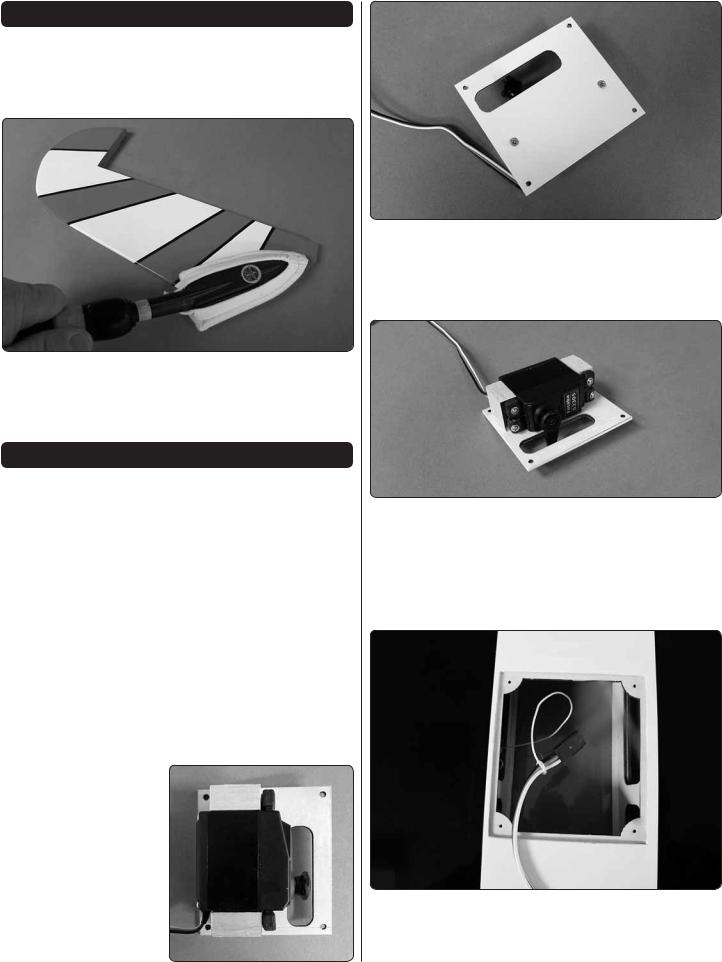
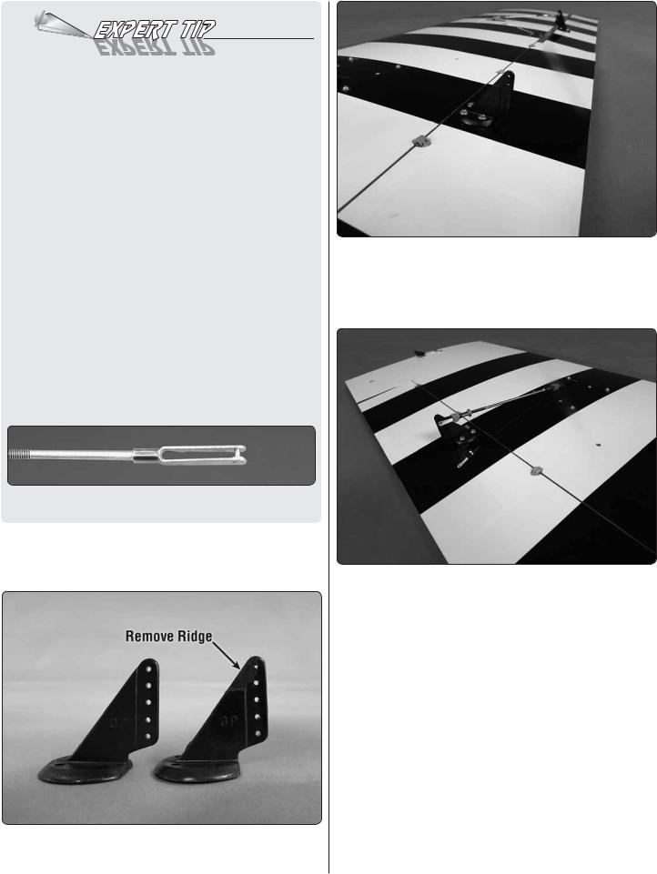
10. Place a black nylon control horn onto the plywood mounting plate in the aileron in line with the servo arm. Drill a 3/32" [2.4mm] hole through each of the holes in the control horn. Drill only through the plywood plate. Do not drill through the top of the control surface. Mount the horn with four #4 x 3/8" [10mm] screws.
11. Each aileron and flap pushrod are made from a 5-3/4" [146mm] 4-40 pushrod wire threaded on one end, a threaded metal clevis, a 4-40 nut, a metal solder clevis and two silicone clevis keepers.
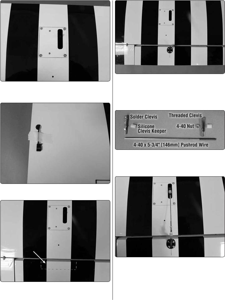
12. Screw the 4-40 nut and the threaded metal clevis onto the pushrod wire. Attach the clevis to the second hole down on the control horn. Attach the metal solder clevis into the outer hole of the aileron servo arm. Center the aileron servo arm and the aileron. Mark on the pushrod wire where to cut the wire. Remove all of the pushrod wire components. Solder the metal solder clevis to the pushrod. If you are not familiar with soldering, read the Expert Tip that follows.
7
HOW TO SOLDER
1.Roughen the end of the pushrod with coarse sandpaper where it is to be soldered. Use denatured alcohol or other solvent to thoroughly clean the pushrod.
2.Apply a few drops of soldering flux to the end of the pushrod, and then use a soldering iron or a torch to heat it. “Tin” the heated area with silver solder by applying the solder to the end. The heat of the pushrod should melt the solder – not the flame of the torch or soldering iron – thus allowing the solder to flow. The end of the wire should be coated with solder all the way around.
3.Place the clevis on the end of the pushrod. Add another drop of flux, then heat and add solder. The same as before, the heat of the parts being soldered should melt the solder, thus allowing it to flow. Allow the joint to cool naturally without disturbing. Avoid excess blobs, but make certain the joint is thoroughly soldered. The solder should be shiny, not rough. If necessary, reheat the joint and allow to cool.
4.Immediately after the solder has solidified, but while it is still hot, use a cloth to quickly wipe off the flux before it hardens. Important: After the joint cools, coat the joint with oil to prevent rust. Note: Do not use the acid flux that comes with silver solder for electrical soldering.
This is what a properly soldered clevis looks like – shiny solder with good flow, no blobs and flux removed.
13. Once the solder has cooled slide a silicone clevis keeper over each clevis. Install the pushrod wire assembly to the aileron servo arm and aileron control horn.
14. The flap control horn needs to be modified. Trim a control horn as shown. A high speed motor tool works well for this.
15. Install the modified control horn to the flap. However, the flap horn is rotated 180° from the direction the aileron horn was installed. Install the horn using the same method used for the aileron. Make sure the base of the horn is even with the flap leading edge.
16. Screw the 4-40 nut and the threaded metal clevis onto the pushrod wire. Attach the clevis to the second hole down on the control horn. Attach the metal solder clevis into the outer hole of the flap servo arm. For the flap servo you will not center the servo. Instead, make sure the flap is fully closed to the bottom of the wing.Then position the servo arm so that it is rotated toward the wing trailing edge. Now you can proceed with making the pushrod wire assembly.
Mark on the pushrod wire where to cut the wire. Remove all of the pushrod wire components. Solder the metal solder clevis to the pushrod. Once the solder has cooled slide a silicone clevis keeper over each clevis. Install the pushrod wire assembly to the servo arm and control horn.
17. Repeat steps 1-16 for the right wing.
8
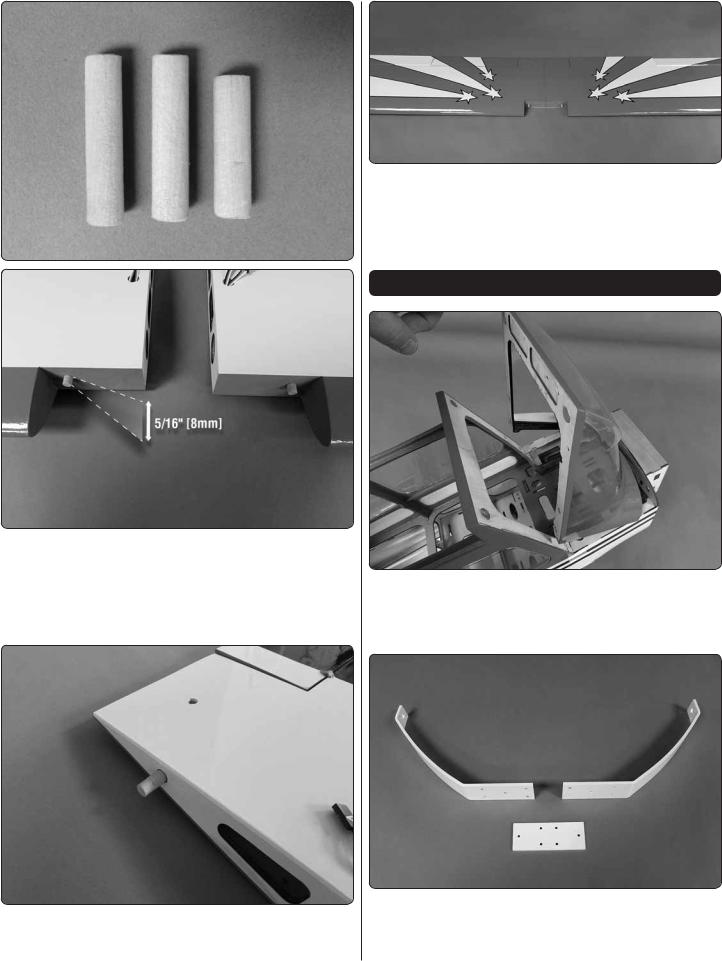
18. The kit includes two 5/16" x 1-5/16" [8 x 35mm] wood dowels and one 5/16" x 1-1/8" [8 x 30mm] wood dowel. Using 5 minute epoxy, glue the two 5/16" x 1-5/16" [8 x 35mm] wood dowels into the holes in the leading edge of both wings. The dowels should be completely seated into the hole. This will allow approximately 5/16" [8mm] to extend out of the wing.
19. Using 5 minute epoxy, glue the 5/16" x 1-1/8" [8 x 30mm] wood dowel into the hole at the trailing edge of the root rib on either the left or right wing.
20. Once the glue has hardened test fit the two wing halves together by inserting the wing tube into one of the wings and then sliding the other wing onto the tube. Once you are satisfied they fit together well, set the wing aside and move on to the fuselage assembly.
ASSEMBLE THE FUSELAGE
1. Remove the windshield from the front of the fuselage. It is attached to the fuselage with magnets. Pull forward on the top of the windshield frame to release the frame from the fuselage.
2. Install the landing gear. With the landing gear in place you will find it easier to handle the fuselage while assembling the components. Locate the landing gear and the landing gear doubler plate.
9

3. Slide the landing gear into the slots in both sides of the fuselage and place the aluminum doubler onto the landing gear. Secure the doubler and the landing gear to the fuselage with ten #6 x 3/4" [19mm] socket head cap screws, #6 lock washers and #6 flat washers. Apply a drop of thread locker to each of the screws. NOTE: The landing gear will have a slight forward sweep when installed correctly.
Install the Stabilizer and Rudder
1. Locate the stabilizer and vertical fin. Test fit them in place on the back of the fuselage.
2. Use a felt tip pen to outline the fin on the top of the stabilizer and to outline the fuselage on the bottom of the stabilizer.
10
3. Remove the fin and stabilizer from the fuselage. Cut the covering from the stabilizer just inside of the lines you have drawn. Be careful to only cut through the covering. DO NOT cut the wood structure. You may find it easiest to cut the covering away using the Expert Tip “How to Cut Covering from Balsa”.
HOW TO CUT COVERING FROM BALSA
Use a soldering iron to cut the covering from the stab. The tip of the soldering iron doesn’t have to be sharp, but a fine tip does work best. Allow the iron to heat fully.
Use a straightedge to guide the soldering iron at a rate that will just melt the covering and not burn into the wood. The hotter the soldering iron, the faster it must travel to melt a fine cut. Peel off the covering.
4. Install the wing on top of the fuselage securing it with two 1/4-20 x 2" [51mm] nylon wing bolts. Glue the horizontal stabilizer and vertical fin in place on the fuselage with 30 minute epoxy. Any excess glue can be cleaned up with paper towels and rubbing alcohol. Before the glue hardens check the alignment of the stab in relation to the wing to be sure they are aligned with each other. After you are satisfied things are aligned, leave the parts undisturbed until the glue has hardened.
5. Locate six hinges. Apply a drop of oil to each hinge to prevent glue from getting into the hinge when installing them in the stabilizer.
11
6. Mix 1/4 ounce of 30 minute epoxy. Use a toothpick to apply a small amount of glue into each of the hinge holes in the stab and both halves of the elevator. Apply 30 minute epoxy to one side of each of the six hinges and install them in the holes in the left and right half of the elevator. Clean excess epoxy with a paper towel and rubbing alcohol. Move quickly and apply 30 minute epoxy to the other half of the hinge and then install each elevator to the horizontal stabilizer. Allow the glue to harden.
7. Use the same technique to install the rudder to the fin.
Install the Elevator and Rudder Servos
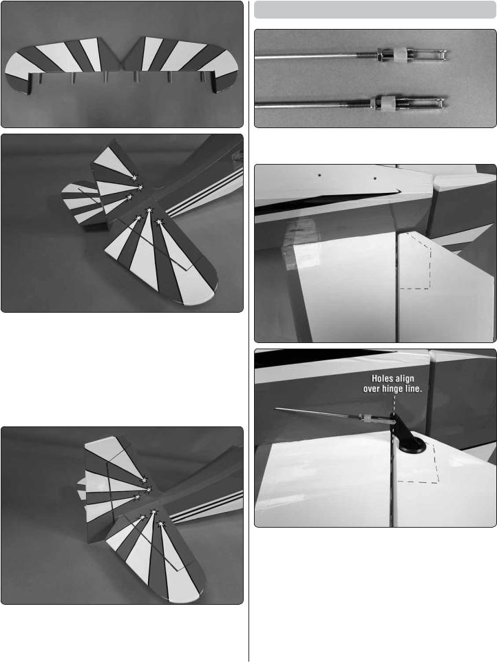
1. Install a 4-40 nut, clevis keeper and 4-40 threaded clevis onto two 4-40 x 48" [1220mm] threaded wires.
2. On the bottom of each elevator there is a plywood plate. Install one of the clevises into the second hole from the bottom of a control horn. Slide the 4-40 wire into the hole in the side of the fuselage and the place the control horn onto the plywood plate. The holes in the control horn should be aligned over the hinge line.
3. Once the horn is properly positioned mark the location of the control horn mounting holes onto the elevator with a felt tip marker. On each of the marks drill a 3/32" [2.4mm] hole through the plywood plate. Do not drill through the top of the elevator!
12
4. Install and then remove a #4 x 3/8" sheet metal screw into each of the holes. Apply a drop of thin CA glue into each of the holes to harden the threads. Once the glue has hardened secure the control horn to the elevator with the four screws.
5. Use the same technique for the remaining elevator half.
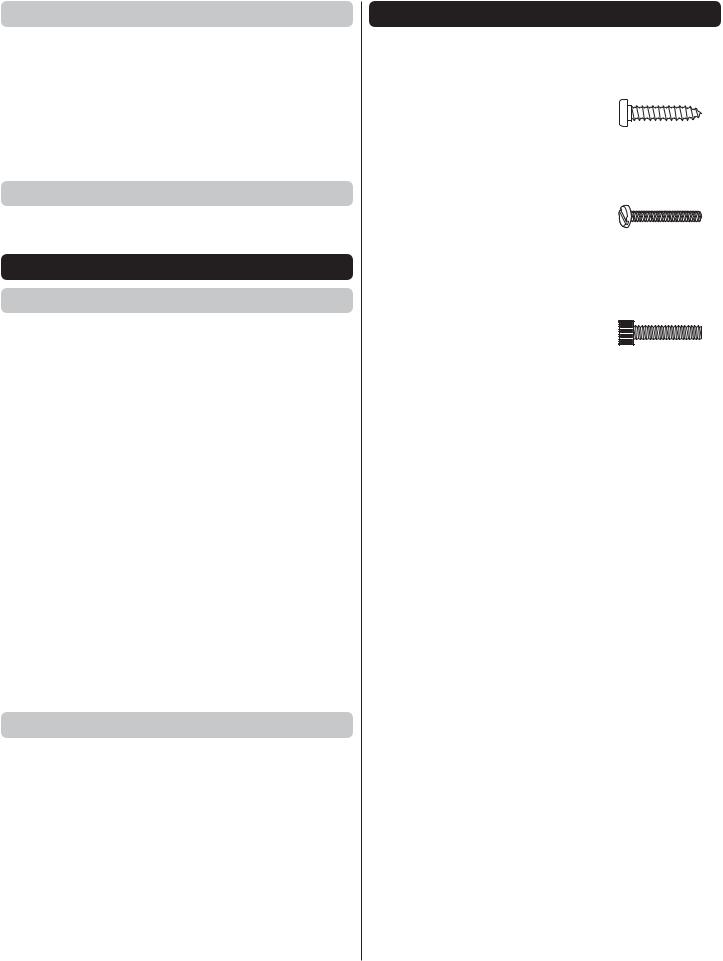
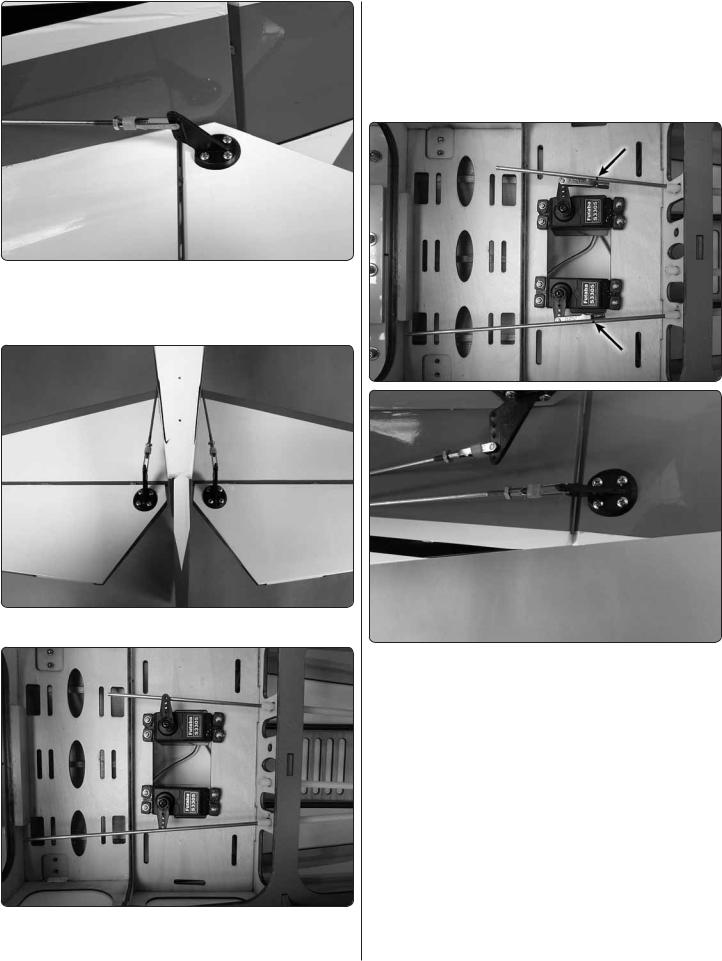
6. Install the grommets and eyelets onto two servos. Cut three arms from a four arm servo horn, center the servo and install the horn onto the servo. Install a 4-40 solder clevis into
the outer hole in each of the servo arms. Place the two servos in the servo tray with the servo arms aligned with the pushrod wires. Drill a 1/16" [1.6mm] hole through each of the mounting holes in the two servos. Install and remove a servo mounting screw into each of the holes you drilled. Apply a drop of thin CA glue to harden the threads. When the glue has hardened, secure the servos with the screws.
7. Center the elevator halves and the two elevator servo arms. Using the solder clevis as your guide, make a mark on the pushrod wire where it needs to be cut. Remove the clevis from the elevator control horn and remove the pushrod from the fuselage. Do this for both pushrod wires.
Once the wires have been removed cut the wires on the marks you made. Solder a 4-40 solder clevis to the wire using the same procedure used on the ailerons. When the solder has cooled remove the threaded clevis and 4-40 nut from the threaded end of the wires. Slide a silicone clevis keeper onto the solder clevis. Re-install the wire through the front of the fuselage into the pushrod guide tubes. Attach the clevis from each pushrod wire to the outer hole of the servo arm. Re-install the nuts and threaded clevises onto each wire, adjusting them so that the elevators are centered. Then secure the elevators with the clevises.
8. Install a 4-40 nut, clevis keeper and 4-40 threaded clevis onto the remaining 4-40 x 48" [1220mm] threaded wire.
13
9. Just like the elevator there is a plywood plate at the bottom of the rudder. Install the clevis into the second hole from the bottom of a control horn. Slide the 4-40 wire into the hole in the side of the fuselage and the place the control horn onto the plywood plate. The holes in the control horn should be aligned over the hinge line.
10. Once the horn is properly positioned mark the location of the control horn mounting holes onto the rudder with a felt tip marker. On each of the marks drill a 3/32" [2.4mm] hole through the plywood plate. Do not drill through the top of the rudder!
11. Install and then remove a #4 x 3/8" sheet metal screw into each of the holes. Apply a drop of thin CA glue into each of the holes to harden the threads. Once the glue has hardened secure the control horn to the elevator with the four screws.
12. Install the grommets and eyelets on to a servo. Cut three arms from a four arm servo horn, center the servo and install the horn onto the servo. Install a 4-40 solder clevis into the outer hole in each of the servo arms. Place the servo in the servo tray with the servo arms aligned with the pushrod wire. Drill a 1/16" [1.6mm] hole through each of the mounting holes in the two servos. Install and remove a servo mounting screw into each of the holes you drilled. Apply a drop of thin CA glue to harden the threads. When the glue has hardened secure the servo with the screws.
13. Center the rudder and the rudder servo arm. Using the solder clevis as your guide, make a mark on the pushrod wire where it needs to be cut. Remove the clevis from the rudder control horn and remove the pushrod from the fuselage. Cut the wire on the mark you made. Solder a 4-40 solder clevis to the wire using the same procedure used on the elevators. When the solder has cooled remove the threaded clevis and 4-40 nut from the threaded end of the wires. Slide a silicone clevis keeper onto the solder clevis. Re-install the wire through the front of the fuselage into the pushrod guide tubes. Attach the clevis from each pushrod wire to the outer hole of the servo arm. Re-install the nut and threaded clevis onto the wire, adjusting it so that the rudder is centered.Then secure the rudder with the clevis.
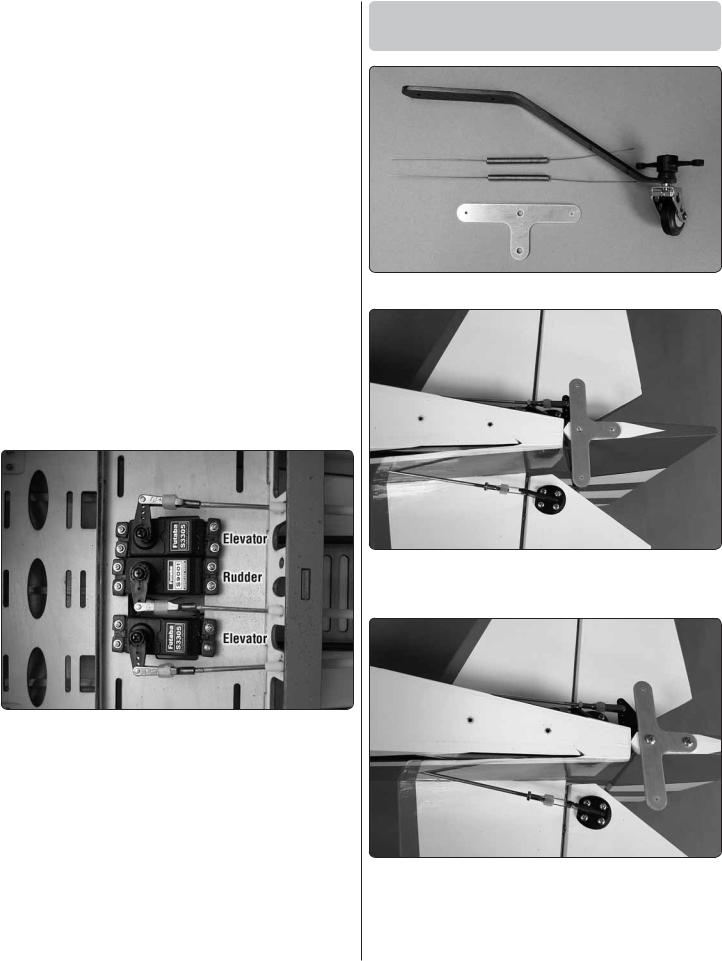
Mount the Tail Wheel, Bracket
and Support Wires
1. Locate all of the components of the tail wheel assembly.
2. Place the aluminum “T” bracket on the bottom of the rudder. Mark the location of the mounting holes with a felt tip marker onto the bottom of the rudder.
3. Drill a 3/32" [2.4mm] hole into the rudder on each of the marks. Insert and then remove a #4 x 3/8" [9.5mm] sheet metal screw into each of the holes you drilled. Apply a drop of thin CA glue into each of the holes to harden the threads. Once the glue hardens secure the “T” bracket to the rudder with two #4 x 3/8" [9.5mm] screws.
14
 Loading...