Great Planes GPMR2400 User Manual

C.G. MACHINE™
ASSEMBLY INSTRUCTIONS
Not designed for use with planes under 2 lbs flying weight.
Thank you for purchasing the Great Planes® C.G. Machine. We are glad you realize the importance of properly balancing your model and the effects the C.G. location has on the way it flies. Although checking the C.G. is often one of those last minute “oh, I’d better do that before I get to the flying field” procedures, the C.G. location can have a profound effect on the way all models handle and respond to control inputs. Therefore, determining and shifting your model’s C.G. is an operation that you should perform with care and accuracy. That’s where the Great Planes C.G. Machine comes into play. With the Great Planes C.G. Machine, you can accurately and easily balance your model according to the manufacturer’s recommendations, and then make incremental changes to the C.G. location to alter your model’s flight characteristics according to your flight skills and preferences.
Great Planes Model Manufacturing
P.O. Box 788
Urbana, Illinois 61801
(217) 398-8970
Entire Contents © Copyright 2004 |
BALP01 v1.1 |
Undoubtedly, you have an airplane on which you are anxious to test your C.G. Machine, so let’s get started!
TOOLS AND SUPPLIES REQUIRED FOR ASSEMBLY:
Thick or medium CA Hobby knife
Phillips screwdriver Small metal file
Thread locking compound 600 & 220-grit sandpaper Small 90° triangle
Tissue or paper towel
Rubbing alcohol or glass cleaner
C.G. MACHINE PARTS
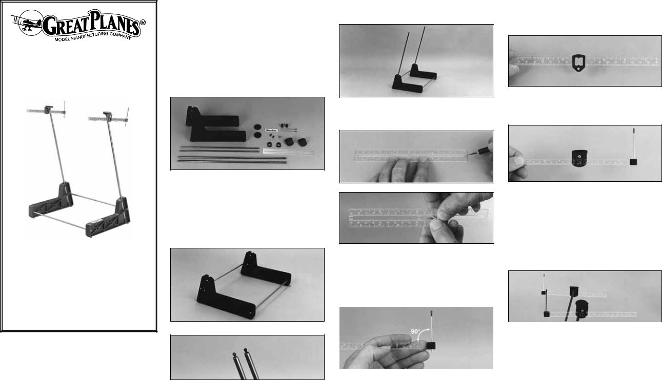
1. Examine all molded plastic parts, and trim off any mold flashing with a sharp hobby knife. Examine the ends of the metal rods for burrs, and carefully remove them with a metal file or emery cloth.
ASSEMBLY SEQUENCE
2. Insert the two 3/16" x 12" steel base joiner rods into the holes in one of the molded plastic bases. Both of the bases are the same so there is not a right or a left. The joiner rods should fit snug, but if they are too tight, lightly lubricate them with bar soap. If the rods are still too tight, carefully enlarge the holes in the base with a 3/16" drill bit or a round file.
Carefully remove any burrs on the pivot balls with a small file. Clean the pivot balls with a tissue.
5. Push the 1/4" steel upright rods all the way into the bases. If there is much resistance, carefully enlarge the holes with a 1/4" drill bit or a round file.
6. The plastic ruler set consists of two rulers, connected by three tabs. Use a hobby knife to cut part-way through each tab on both sides of the rulers, then carefully flex and snap the rulers apart. Trim the remaining tabs flush with the edge of the rulers, then finish with a flat sanding block and 220-grit or finer sandpaper.
7. Insert the .074" x 2-1/2" wire pointers into the plastic ruler end caps. This should be a secure friction fit.
9. Apply a drop of thick or medium CA to both sides of the ruler at the “zero” end, insert the ruler fully into the slot in the end cap, then immediately confirm that the pointer wire is vertical. Attach a ruler end cap to each of the rulers.
10. Check the fit of the rulers in the molded plastic ruler holders. The rulers should slide freely in the ruler holders. If they do not, carefully sand the edges of the rulers with a sanding block and fine sandpaper until the rulers slide freely.
11. Loosely attach the ruler holder to the molded plastic socket cap with a #4 x 3/8" screw.
12. Insert the ruler through the ruler holder, then tighten the screw only enough to provide friction. Do not overtighten the screw, as this may deform the plastic.
13. Clean the top of the socket caps with a tissue or paper towel dampened with rubbing alcohol or glass cleaner. Peel off the backing from the foam rubber pads, then apply the pads to the tops of the socket caps.
3. Join the other base to the joiner rods the same way.
|
|
14. Snap the socket caps onto the steel balls on the upright rods. |
|
|
|
There is not a front or a rear to the C.G. Machine so at this time it does |
|
|
|
not matter onto which upright rod you install the socket caps. |
|
|
|
15. Pivot the socket caps throughout their range of motion to check |
|
|
|
for free movement. If there is a significant amount of friction between |
|
|
|
the cap and the ball, remove the cap and snap it on again, moving |
|
|
|
and spinning it around. If there is still too much friction, polish the steel |
|
8. Slide the ruler end caps onto the rulers. When the ruler end caps |
|||
ball with 600-grit sandpaper and coat it with a thin film of bar soap. |
|||
are fully seated, the pointers should be perpendicular to the ruler – you |
|
||
4. Thread the two 2-56 threaded steel pivot balls into the ends of |
can use a small 90° triangle to check. If it is necessary to adjust the |
16. Apply the peel-and-stick decal to the top edge of one of |
the 1/4" steel upright rods with a drop of thread locking compound. |
fit, sand the end of the ruler slightly or trim the slot in the ruler end cap. |
the bases. |
 Loading...