

Grandview LF-MIRCII User Manual
L
2.35:1
LF-MIRC ( )84
LF-MIRC ( )100
LF-MIRC ( )120
LF-MIRC ( )77
LF-MIRC ( )80
LF-MIRC ( )92
LF-MIRC ( )100
LF-MIRC ( )106
LF-MIRC ( )120
LF-MIRC ( )100
LF-MIRC ( )110
LF-MIRC ( )120
LF-MIRC ( )130
LF-MIRC ( )140
Ⅱ
Ⅱ
Ⅱ
Ⅱ
Ⅱ
Ⅱ
Ⅱ
Ⅱ
Ⅱ
Ⅱ
Ⅱ
Ⅱ
Ⅱ
Ⅱ
B1
84
100
120
77
80
92
100
106
120
100
110
120
130
140
W
1707x12 80
2032x15 24
2438x18 29
1705x 959
1771x 996
2037x11 46
2214x12 45
2347x13 20
2657x14 94
2337x 995
2571x10 94
2805x11 93
3038x12 93
3272x13 92
B3
170
170
GRANDVIEW REPRODUCING GENUINE COLORS
A
H
B2
Instruction Manual for
Cyber Series Recessed-Ceiling Screen
B1 B2 B3
2326
2651
3057
2324
2390
2656
2833
2966
3276
2956
3190
3424
3657
3891
2196
2195
2480
2195
2197
2197
2196
2196
2195
2201
2200
2199
2199
2198
100
100
100
100
100
100
100
100
100
100
100
100
100
100
55
55
55
55
55
55
55
55
55
55
55
55
55
55
665
420
400
985
950
800
700
625
450
955
855
755
655
555
2431x26 0x 226
2756x26 0x 226
3162x26 0x 226
2429x26 0x 226
2495x26 0x 226
2761x26 0x 226
2938x26 0x 226
3071x26 0x 226
3381x26 0x 226
3061x26 0x 226
3295x26 0x 226
3529x26 0x 226
3767x26 0x 226
4001x26 0x 226
32.6/35 .8
35.9/39 .9
40.4/44 .8
32.2/35 .6
33.0/36 .4
35.5/39 .5
37.4/41 .4
38.8/43 .0
42.1/46 .7
38.4/42 .6
40.7/45 .2
43.2/48 .0
49.2/54 .3
52.0/57 .2
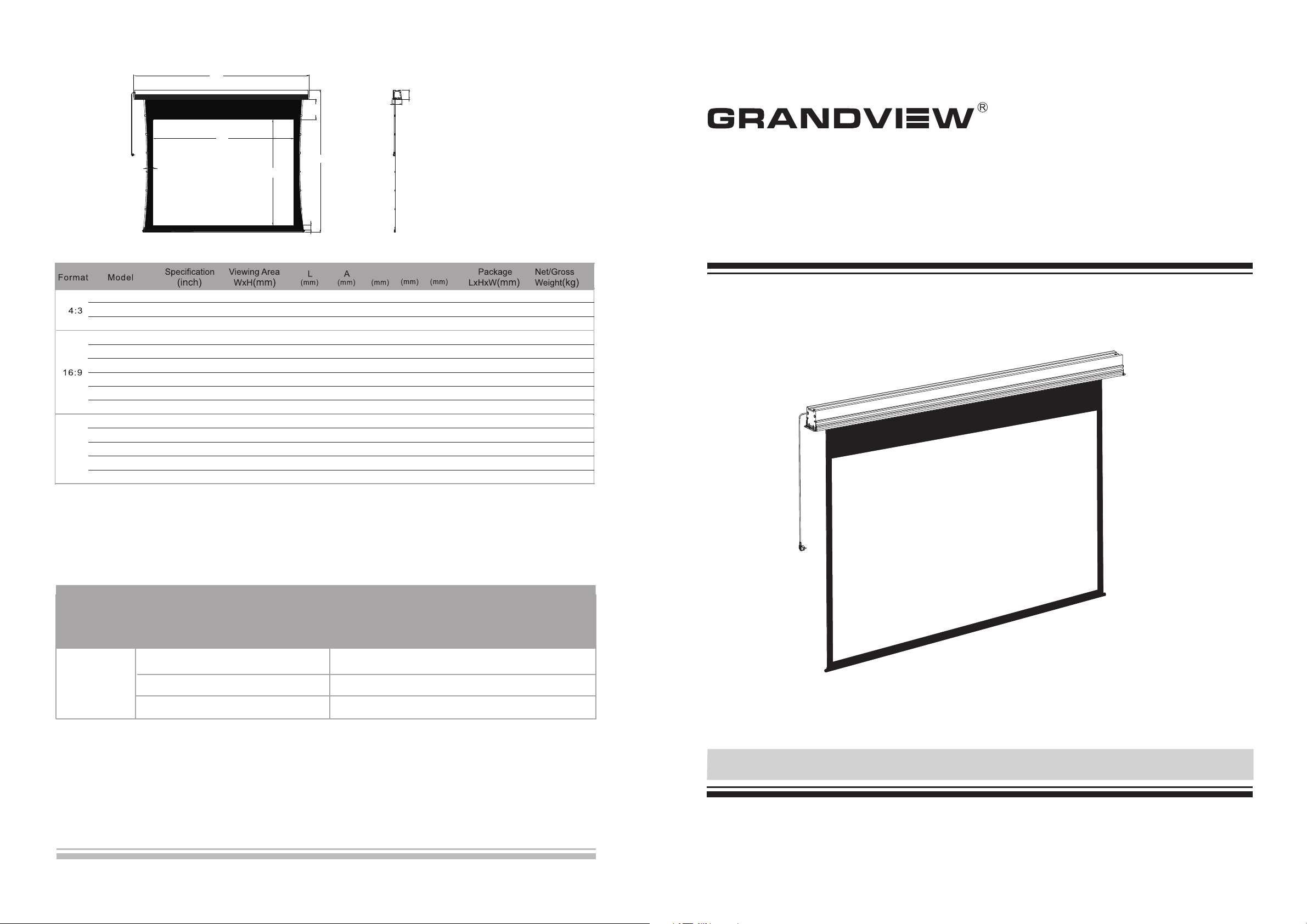
Note:
1. Due to product updates, sizes and specifications are subject to change at any time.
The tolerance for L is approximately ± 5mm (3/16 inches).
2. Actual dimension is measured by: total screen length L x end cap depth x end cap height.
Questions & Answers
Fabr ic s of Grandview moto ri zed screen can be u se d for years, most pro bl ems are cost by simpl e incidents. If
prob le m occurs, please fi nd the list below for s om e common solution s. If problems keep o n, p lease contact
auth or ized agent of Grand view or call servic e nu mber: (8620)348 06166
Reas on Solu ti on
Scre en r esponds
noth in g to any
Batt er y mis-installed o r po werless
oper at ion
Power line disconnection
One year warranty
Grandview provides one year warranty for motorized screen. Contents of warranty include replacement of spare
parts while problems occur with correct operation. Not include inappropriately operating the screen or uninstall the
screen by self. You should reserve in advance for the repair with Grandview or appointed service center.
Please check about the batteries as instruction manual.
Please connect the power line as instruction manual.
Model:CB-MIRC or LF-MIRC(Ⅱ) (Ⅱ)
Http: //www.grandvie wscreen .com
Thank you for purchasing a Grandview projection screen.
Before use, please read instructions carefully. After installation, store instructions for future reference.
Caution
Warnings: Please preve nt scre en from w et place to avoid electric or fire dangerous.
1. Please read carefully with this instructions before installation to avoid damage to product causing
by inappropriate installation or operation.
2. Please keep the screen away from hot sources, such as radiator, heating machine, fireplace,
loudspeaker or other relative device.
3. Only Plug with ground wire is acceptable.
4. Only accessories from authorized supplier is acceptable.
5. Please unplug the power wire when lighting and raining or not use with a long time.
6. Please contact the professional for installation and repairing.
7. Please prevent screen from wet and water .
8. As soon as the plug of the screen is connected to the power source, the screen is connecting
with electricity.
9. Please use the approved power line (three-core power line)/ device interface/power plug.
10. Please use the rating (voltage, amps) power line (three-core power line) / device interface/power
plug. If have any questions about power line/ device interface/power plug, please contact the
professional people.
11. After installation, please locate a power device in order to disconnect power or connect the power
plug to electrical socket. This electrical socket should be installed to a convenient position. If the
accident occurs during operation, please disconnect power or take out the power plug.
12. The ceiling or wall used for fixture installation must be secure enough; load-bearing requirement
must be 4 times of the screen to prevent the screens from falling.
13. Before using, please remove the fixation strap and screws from the low bar to avoid the damage of product.
(1) Fo r ad justing the viewi ng area, please ins er t the adjustment to r egulate adjustm en t hole. A
cloc kw ise adjustment wi ll increase the vie wi ng area for about 13m m.
Note : Aft er pressing the up bu tt on, you will need a f ew s econds to see the adj us tment of screen ;
and af te r pressing the down b utton, you will see t he p osition changed o f screen.
Plea se d o not operate the fol lowing step befor e st ep1 to avoid damage s of screen.
(2) A coun te rclockwise cycl e can adjust the dist an ce to 13mm between ca sing and rod.
Please be careful whi le o pe ra ting, too much retrac ti ng w ill cause the damages of sc re en a nd motor.
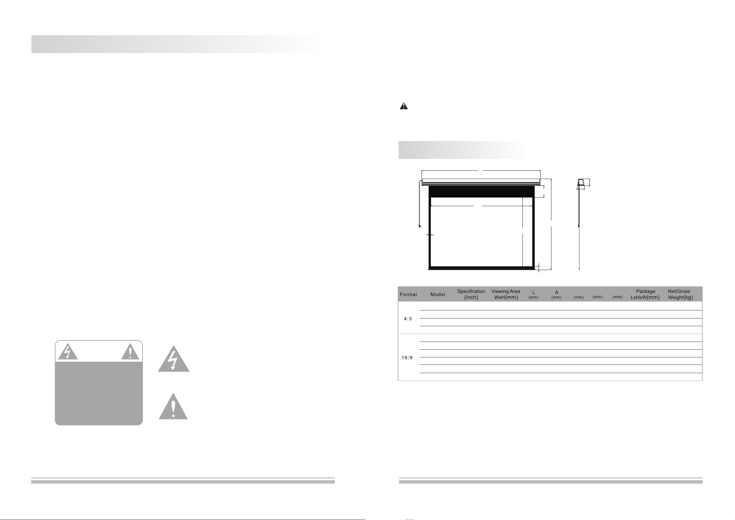
Product Specifications
L
B1
B1
W
H
B3
170
A
170
Warnings
To prevent from electric
dangerous, please don't
remove the end cap. There
is no need for users to
check the parts inside,
please handle the problems
to professional repairman.
Please notice the non-insulated voltage of the
spare parts to prevent from electric dangerous.
Please operate according to the user manual
with the screen.
B2
B1 B2 B3
CB-MIRC ( )72
CB-MIRC ( )84
CB-MIRC ( )100
CB-MIRC ( )120
CB-MIRC ( )77
CB-MIRC ( )80
CB-MIRC ( )92
CB-MIRC ( )100
CB-MIRC ( )106
CB-MIRC ( )120
Note:
1. Due to product updates, sizes and specifications are subject to change at any time.
The tolerance for L is approximately ± 5mm (3/16 inches).
2. Actual dimension is measured by: total screen length L x end cap depth x end cap height.
Ⅱ
Ⅱ
Ⅱ
Ⅱ
Ⅱ
Ⅱ
Ⅱ
Ⅱ
Ⅱ
Ⅱ
72
84
100
120
77
80
92
100
106
120
1463x10 97
1707x12 80
2032x15 24
2438x18 29
1705x 959
1771x 996
2037x11 46
2214x12 45
2347x13 20
2657x14 94
1852
2136
2461
2867
2134
2156
2466
2643
2776
3086
2158
2161
2155
2160
2160
2157
2157
2156
2161
2155
30
50
50
50
50
28
50
50
50
50
50
50
50
50
50
50
50
50
50
50
850
670
420
120
990
950
800
700
630
450
1913x26 0x 226
2197x26 0x 226
2522x26 0x 226
2928x26 0x 226
2195x26 0x 226
2217x26 0x 226
2527x26 0x 226
2704x26 0x 226
2837x26 0x 226
3147x26 0x 226
24.8/27 .8
29.4/32 .6
32.7/36 .3
36.3/40 .4
29.9/33 .2
30.2/33 .5
33.1/36 .6
34.7/38 .5
36.0/39 .8
39.1/43 .5
1
14

D. External Wall Switch (optional)
The wall switch is available for a fixed location. Please
connect RJ11 plug to EXTCTRL input on the screen.
Note: please use a cord for a far location.
Wal l Sw it ch
(optional)
Description
Aluminum Casing
E. Synchro Power Relay(optional)
After conne cting the Wireless Synchr o
Conver ter, the scr een can be cont rolled
by FM modul ation wireless cont roller
which can coope rate with Sychr o Power
Relay and swi tch of projector to cont rol
the up and down of scr een synchr onous ly.
Sychro Power Relay and
Wireless Synchro Converter
IR to RF receiver
Power Synchro
and IR
三. Screen Adjustment
(Please take apart th e ba ffle when adjus ti ng t he s creen. And please rein st al l th e baffle afte r ad ju st ing.)
Motor Positioning
Avoid the over heating of motor; p le ase do not use the scre en
over 4 s ec onds for extendin g and retracting co nt inuously. The
moto r ne eds 4 minutes to cold d own and the motor do no t ne ed
any lu br icant. The standard fac to ry setting of upper a nd l ower
limi ta tion is perfect. To avoid the d am age, please conta ct the
prof es sional people or lo cal dealers for rep ai ring.
Plea e ad just the motor adju sting slot using M4 a ll en key
“ ”
Screen Extending Adjustment
Oper at e the adjustment wh en t he screen exten ds c ompletely
(1) Fo r ad justing the viewi ng area, please ins er t the adjustment to r egulate adjustm en t hole. A clockwise
adju st ment will increas e the viewing area fo r ab out 13mm.
Note : Aft er pressing the Up bu tt on, you will need a f ew s econds to see the adj us tment of screen ; an d after
pres si ng the down button, y ou w ill see the posit io n changed of screen .
(2) Wi th t he over-adjustm en t, a counter-cl oc kwise adjustmen t wi ll return the scr ee n. Thi s ad justment can be
oper at ed when the screen st ops at the lowest pos ti on without contro ll ing.
“ “
“ “
Motor adjusting slo t
:
Front Vie w
Accessaries
M12 Bar (4p cs)
Wrench (1 pc )
Infra re d Remote C on tro l ler (1pc)
M12 Nut (12pcs)
Hanging Board (2pcs )
External Infrar ed R ec ei ver (1pc)
Side Vi ew
P o w e r l i n e
Screen Fabric
Low Bar
Hook (4pcs) Pressing Piece (2pc s)
M6 Allen Screw (4pcs)
Tri gg er L ine (1pc)
M6 Nut (4pcs)
Hook
M12 Nut
M12 Bar
Bracket
M10X100 Expansion
Screw (8pcs)
M5 Screw (4pcs)
Instruction Man ua l (1 pc )
Please be careful whi le o pe ra ting, too much retrac ti ng w ill cause the damages of sc re en a nd motor.
“ ”
Screen Retracting Adjustment
Refe re nce:
(Not e: This ad justment is not saf et y, plea se c ontact the profes sional people for r ep airing and avoi d da maging of
scre en a nd warranty failu re)
“ ”
Caut io n we str on gly recommend tha t do n ot regulate the s cr een limitation pr iv ately. The st an dard limitati on o f
scre en i s set from the factor y an d this standard can s atisfy the requir em ent of users.
13
2
 Loading...