

Page 1
GRANDVIEW REPRODUCING GENUINE COLORS
GRANDVIEW REPRODUCING GENUINE COLORS
GRANDVIEW REPRODUCING GENUINE COLORS
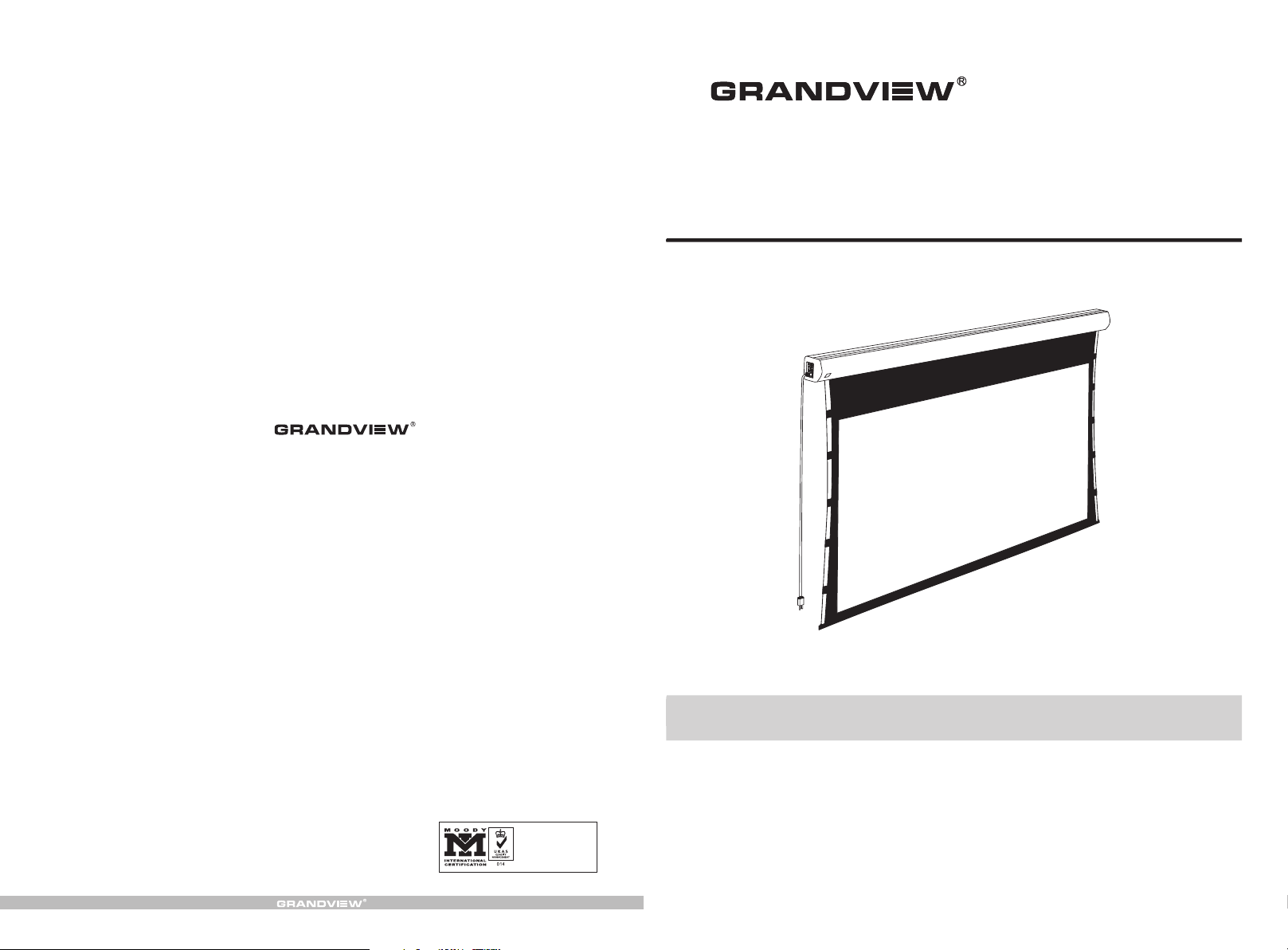
Cyber Series Intellectualized-Controlled Screen
Instruction Manual for
Grandview Crystal Screen Canada Ltd.
#11- 3751 North Fraser Way,
Marine Way Business Centre,
Burnaby, BC, Canada V5J 5G4
Tel: 1-604-412-9777 Fax: 1-604-412-9796
Website: www.grandviewscreen.ca
Guangzhou Grandview Crystal Screen Co., Ltd.
P.O. 511400 Federal Ind. Zone No. 363, Yushan West Road,
Shiqiao, Panyu District, Guangzhou, Guangdong, China
Tel: +8620-8489-9499 Fax: +8620-8480-3343
Website: www.grandviewscreen.com
ISO9001:2000
International Certification
Model:CB-MIxx
Thank you for purchasing a Grandview projection screen.
Before use, please read instructions carefully. After installation, store instructions for future reference.
Page 2
Description
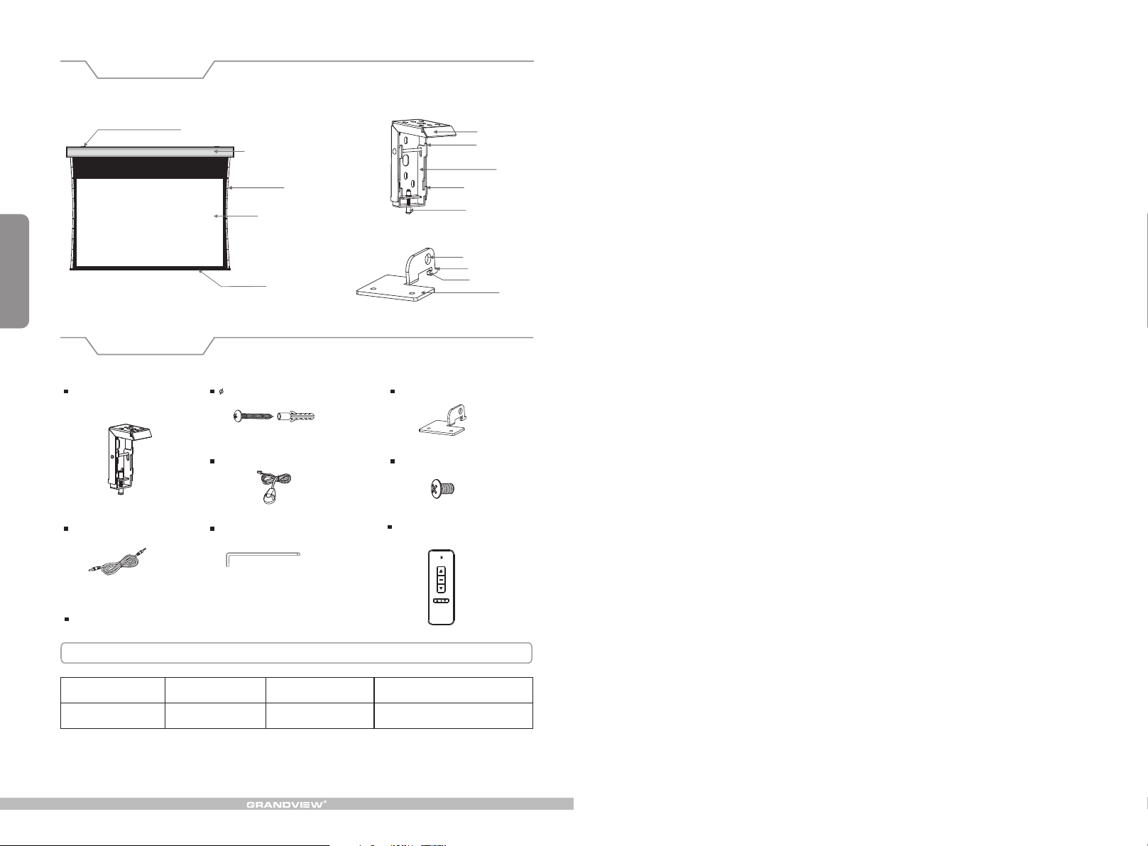
1
Floating wa ll brac ket
Accessaries
Floating wa ll brac ket (2pcs)
Trigger line ( 1 pc )
Alluminium housing
String
Screen fabric
Bottom rod
5×40mm Tapping screw & cap (8sets)
Externnal IR Rece iver ( 1 )pc
Allen key (1pc)
Down buck le
Fixing sc re w
Hanging h ol e
Front but to n
Back butt on
Ceiling h an ge r (2pcs)
M6x10 Screw (4pcs )
Remote
(1p
Con
tro
ller
Top panel
Up buckle
Baffl e
Base
c
)
I
nstru
c
t
i
on ma
n
u
al
(1
p
c)
Motorized Screen Power Specifications
Voltag e Fre qu en cy
230V/1 20 V/100V
50Hz/6 0Hz 90W/8 0W
Wat ts
Appli ca tion
Applies up to 120" moto rized screen s
Page 3
Warnings
The ceiling or wall used for fixture installation must be secure to prevent the screens from falling.
While installing electrical motors, please hire professionals or your local dealer to ensure safety. A misconnection
may lead to fire or leaks.
Make sure the Fixing screw be fastened when using the wall bracket, to avoid any damage.
Keep all infrared wireless products away from fluorescent lighting as it may cause malfunctions.
Please read the following as any damage to the screen surface will affect the quality of the picture:
1.Avoid contact or touching the screen surface as it may cause scratches or tears.
2.Do not write or draw on the surface.
3.Clean the screen with a soft cloth and lukewarm water. Do not use any detergent or cleaning products.
Roll up the screen after every use. Ensure that the screen is level when installing; do not pull on the sides or fold
the screen.
To prevent unnecessary damage, the operating and maintenance of the screen should be done by adults.
Installation
Take out all the parts from the packaging and follow the accessagires guideline to ensure you have all parts.
There are three installation measures for this product, namely wall mounting, ceiling mounting and ceiling hang. The
installed distance can be changeable up to your needs via adjusting the slipper block, while the ideal position is the
mounting bracket is at its nearest point to the endcap, which can reduce unnecessary vibration or noise.
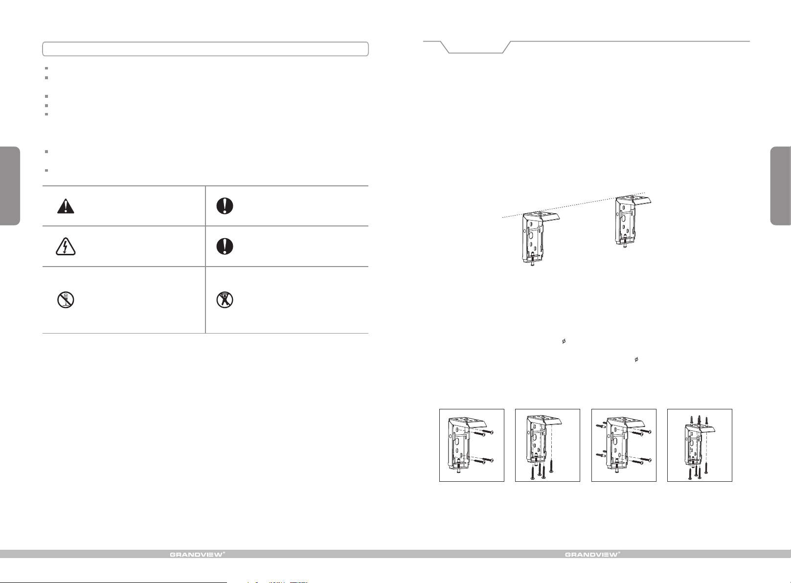
Floating wall bracket installation
1. Choose screws for mounting according to wall material. ( Tips: Wood screws for wood wall, and Tapping screws
for concrete wall.)
2. Mount the brackets onto the wall, assuring they are at the horizontal level. (Tips: draw an erasable level line when
mounting the brackets) (Figure 1) Here below are the details:
9
Ignoring the safety warnings may
lea d t o i nju ries and/or damaging
the product.
Do n ot co nn ect a ny el ec tri ca l
attachments o r remote cont rols.
Please contact your local dealer for
repairs or maintenance. Please contact
our company if you have any further
questions. Avoid tak ing apart the
fixtures your self. Loose p arts may
cause the screen to fall.
Do not take apart and replace with unknown parts. If there are any problems, please contact your local dealer.
Product specifications are subject to change.
Fixtures should be installed in a secure
place to avoid accidents or the screen
falling.
Roll up t he s creen a ft er e ve ry use.
Leaving it ha nging for a l ong period
of time may cause the fabric to loosen.
Refrain from hanging anything on the
screen as it may cause the screen to
fall.
Figure 1
Installation Steps
a) Wood wall and ceiling installation: D rill in the 5 x 40 screws through the appropri ate holes in the bracket
( Figur e 2-3 ).
b) Drywall and ceili ng and instal lation: Ins tall the anch ors and drill in the 5 x 40
( Figur e 4-5).
bracket hol es.
Wood wall installation
Wood ceiling installation
Concrete wall installation
screws into the appr opri ate
Concrete ceiling installation
2
Figure 2 Figure 3
Figure 4 Figure 5
Page 4
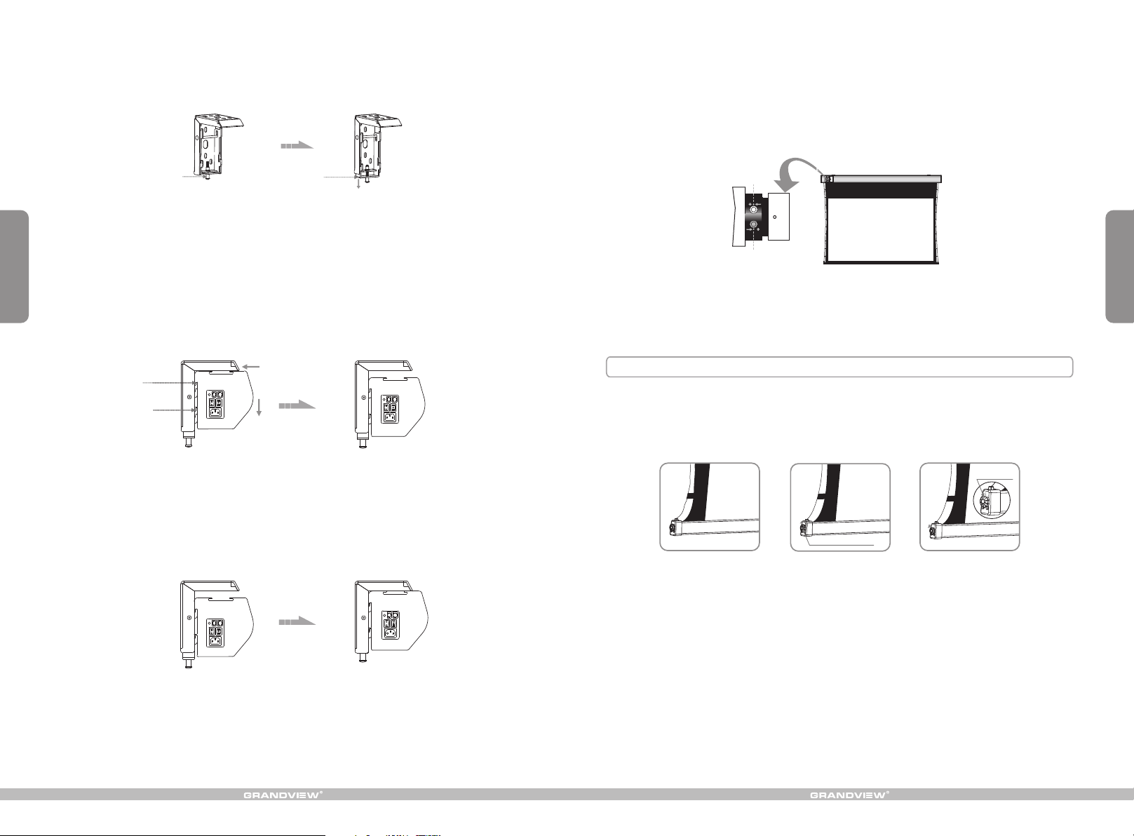
3. L oo se t he Fi xi ng s cr ew to l ow er d own t he B af fl e al l the w ay. ( F ig ure 6 -7 )
Attention:
> Please make sure there is no dust or dirt on the fabric surface before rolling it back to the casing
> The rec omme ned wo rkin g time i s less t han 50 s econ ds. The motor will enter overheating protection
status and stop working for every continuous 4 minuters operation, user would need to wait for a
while until the motor cool down before operating again.
> There i s no lub e need ed for t he mot or. Plea se be no tice d that t he app ropriate setting is optimized
which requires no further adjustment, please consult the after sales team before adjusting the limits.
3
Fixin g sc rew
Figure 6 Figure 7
4. When mounting the screen onto Float ing wall brackets, make sure the Up groo ve and the Dow n groove on the
housing match with the Up buckle and the D own buckle on the bracket seperately. ( Figure 8-9 ).
Up gro ove
Down g roov e
Fi gu r e 8 Fi gu r e 9
5. Fasten the F ixin g screw on the bracke t, to fix housing tig htly o nto the brack ets. ( Figure 10-11 )
Baffl e
Retraction Limit
Drop Limit
How to adjust tension situation of the string
If the string is loose which is caused by bump on transportation or faulty operation (Figure 30), please rotate the
String Adjustment Knob clockwisely to make string tensional (Figure 31). If the string is over-tensional, please press
the String Releasing Button and then rotate the String Adjustment Knob counter-clockwisely to suitable tensional
situation (Figure 32).
String Releasing
Button
String Adjustment Knob
Figure 30 Figure 31 Figure 32
8
Figure 10 Figure 11
Page 5
How to use Trigger
1. Insert one end of the signal cable into the jack of the handle controller, and the other end into the
DC5V-12V output hole of the projector .
2
. Switch Manual/Remote Control Button to position "0" (remote control stalls).
Control:
Trigger
(Figure 24-25)
3. When running the projector, the screen will spread the fabric automatic by synchronous; when closing the
projector, screen will be back automatic by synchronous too.
4. If you don't need to use the t , please draw off the burst line directly, then control it by your hand.
rigger control
Floating hanging bracket installation
To choose the tapping screws with hanger or other screws with hanger (unprovided) according to ceiling material.
(Tips: Wood screws 5 x 40 for wook ceiling and tapping screws for concrete wall.)
1. To drill two same holes with an electric drill horizontally with wall, then fasten hangers(unprovided) onto the
ceiling. (Figure 12)
A
7
Figure 24 Figure 25
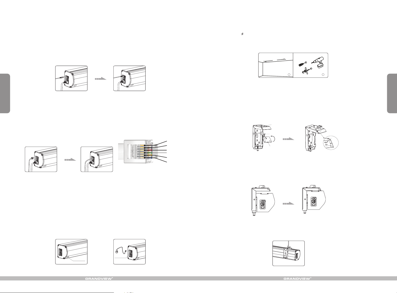
How to use External Control (Central Controller or RS232/USB):
1. Turn the manual/IR remote control switch to position "0" (remote control stalls)
2. Plug one side of the signal cord into the computer output jack at left side of the screen's end cap, the other side
of the singal cord to plug into the jack of Central Controller or computer RS232/USB
Control, an Adapter is necessary to be connected with, the Adapter is not in the accessory package)
(Note: in order to use RS232
(Figure 26-27),
and then you can control up/pause/down of the screen via Central Controller or computer.
RS2 32 3P(T XD)
RS2 32 5P(G ND)
COM
STOP
DOW N
UP
RS232 interface settings:
Figure 26 Figure 27
bps::2400
data bit:8
parity check:no
stop bit:1
control code:
up:0xff,0xee,0xee,0xdd
stop:0xff,0xee,0xee,0xcc
down:0xff,0xee,0xee,0xee
How to use IR Remote Control:
1. Turn the manual/IR remote control switch to position "0" (remote control stalls)
2. When there's nothing to keep our of the IR window, you can use the controller to control up/pause/down of the
screen (Figure 28).
3. For hidden installation or IR window is being kept out by something, please take out the IR Receiver Head and
plug it to the revelant hole, and then install it at the position where IR signal is available (Figure 29)
1
2
Figure12
2. Incline the ceiling hanger to a certain degree to make the hanger hole go through the oval hole in the middle of
top side of the wall bracket. Then level the ceiling hanger to ensure that the base clings to the top of wall bracket,
so that the front button can go right through the wall bracket's fixing hole. Push the ceiling hanger ahead until the
front button fully locks the top panel of the wall bracket. Fix the ceiling hanger to the wall bracket with the help of
M6x10 size of screws. (Figure 13-14) (Note: Make sure the front button of the ceiling hanger fully lock the top side
panel of the wall bracket to prevent the screen falling down.)
Fixing hole
Front button
Base
Front
button
Wall
bracket
Figure 13 Figure 14
3. After fix the ceiling hanger, make sure the up groove and the down groove on the housing match with Up
buckle and Down buckle on the bracket separately and fasten the fixing screw on the bracket, to fix housing
tightly onto the brackets.( Figure 15-16)
Figure 15 Figure 16
4. After finished step 2 and step 3, check whether wall bracket fix on the housing of screen tightly then you can
hang the screen according to the figure 17.
4
Inner IR Receiver
Window
External IR Jack
Figure 28 Figure 29
Figure 17
Page 6
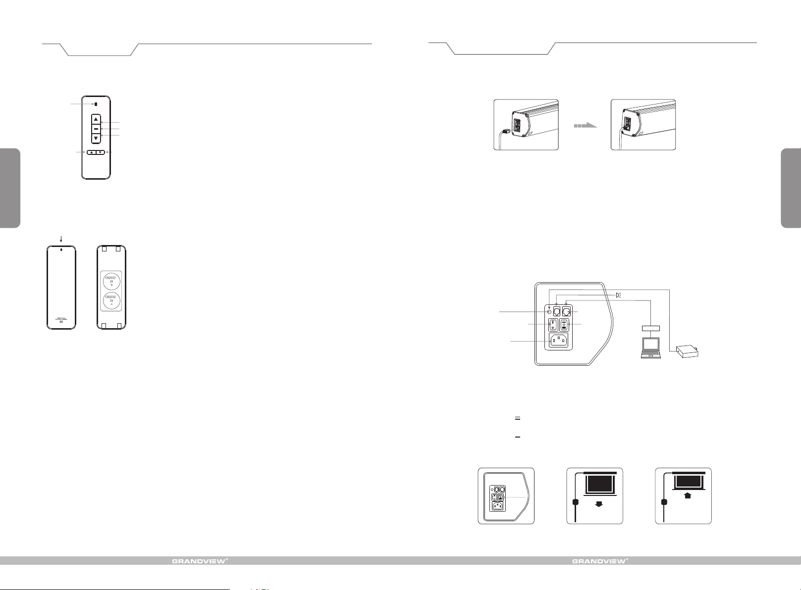
LED
Micro-up
Instructions
Micro-down
UP
STOP
DOWN
Button Function a nd Operation Inst ruction :
1.Press UP button to lift th e screen
2.Press STOP button to stop the scr een
3.Press DOWN butt on to lower the scree n
4.Press MIC RO-U P butto n to retract the scre en in small
increments(15 0ms for each moveme nt)
5.Press MIC RO-D OWN button to lower t he screen in small
increments (150 ms for each movemen t)
Operation Instruction
Power Cord Connecting Screen:
1. Plug the power cord into the power jack on the left end cap (Figure 18-19). (Attention: The plug slot must be
matched with the power jack slot)
Figure 18 Figure 19
5
Model:AC127
Push down
Cautions:
1.The minimum dis tance between Con troller and Recei ver: 5 0cm
2.Wor kable within 8m in ho rizontal direct ionf rom the Receiver to t he
Controller
3.Do not cover the Co ntroller ’s launching port w hile o peration
4.Strictl y bano peration in wet or hi gh temperature en viro nment.
5.Replacing bat teries when the sig nal is faint or no sign al.
6.Batteries for t he Controller: 2 un its CR2032 button c ells .
Batteries Insta llation Instruc tion:
When the signal of th e Controller is fai nt, please replac e the ba tteries
as follow steps:
1.Reverse Contr oller to the back, pu sh down as the arrow ma rk to op en
the cover.
2.Installtwo ce lls of battery and se t the direction of po siti ve and
negative electr ode just like the cha rt shows.
3.Close the batte ry cover.
ear off the glue cloth fixed on the bottom rod,ensure the bottom rod is not stuck by the casing.
2. T
3. Switch on the power(within stated voltage).
How to use Manual/Remote Control Switch Button: (Figure 20)
The screen has four kinds of optional control methods: IR Remote Control, Manual Control, Trigger Control, External
Control (Central Control or RS232/USB). When switching the Manual/Remote Control Switch Button to position "1",
you can use Manual Control or Trigger to control up/pause/down of the screen. When switching to position "0", you
can use IR Remote Control or External Control (Central Controller or Rs232/USB) to control up/pause/down of the
screen.
Connecting External IR
Figure 20
Computer Output
Jack
Manual Control
Rs2 32
Central Controller
Projector
Trigger Jack
Manual/Remote Control
Switch Button
Power Cord Jack
How to use manual switch control:
1. Switch Manual/Remote Control Button to position "1" (manual stalls).
Turn the switch to position to lower the screen
2. " " ; it will come down slowly. When it is all the way down, it will
stop automatically (Figure 22) .
3. Turn the switch to " " to the screen; it will go up into the metal casing. When it is all the way up, it
will stop automatically (Figure 23).
4. To stop any time while the screen is in motion, turn the switch to 0.
position lower
6
Manual Control
Figure 21 Figure 22 Figure 23
 Loading...