

Page 1
GRANDVIEW REPRODUCING GENUINE COLORS
GRANDVIEW REPRODUCING GENUINE COLORS
Installation Guide for
Large-Flat series Prestige Concave Permanent Cinema Screen
Grandview Crystal Screen Canada Ltd.
#11- 3751 North Fraser Way,
Marine Way Business Centre,
Burnaby, BC, Canada V5J 5G4
Tel: 1-604-412-9777 Fax: 1-604-412-9796
Website: www.grandviewscreen.ca
Guangzhou Grandview Crystal Screen Co., Ltd.
P.O. 511400 Federal Ind. Zone No. 363, Yushan West Road,
Shiqiao, Panyu District, Guangzhou, Guangdong, China
Tel: +8620-8489-9499 Fax: +8620-8480-3343
Website: www.grandviewscreen.com
www.grandviewscreen.com.cn
ISO9001:2000
International Certification
Model:LF-PHxx(DY)
Thank you for purchasing a Grandview projection screen.
Before use, please read instructions carefully. After installation, store instructions for future reference.
Page 2

Page 3

Warning
Description
When installing , make sure it is facin g forward. Th e back of the scr een wi ll be labeled with a st icker.
Please read the fol lowing as any damag e to the s creen surfa ce wil l affec t the quality of the pi cture:
1.The frame is m ade wi th lightweight al uminum. Please ha ndle w ith care.
2.Avoi d contact or touchi ng the screen surfa ce as it m ay cause scra tche s or tears.
3.Do not write or draw o n the surface.
4.Clean the screen with a soft cloth and lukewarm water. Do not use any detergent or cleaning products.
5.Use a cotton c loth t o carefully wipe off t he dus t on the frame to preve nt any d amages
6.If it is not in us e for a lo ng period of time, co ver the screen to shu t out du st and dirt.
To prevent unnecessary damage , the operating and maintenance of the screen should be done by adults.
Opening the case, the frame has indentations on surface because of packaging in a dry case for a long
time. This is a n orma l phen omen on and t he scr een ca n be use d normally. Please stay the screen in a
8
normal condition that the indentations can be naturally removed. Recovery time will be changed in 1-15
days because of the air humidity, If you wa nt to re move t hese i nden tati ons qu ickl y, please use half-wet
solution.
Methods: Sprinkle water on the surface that can remove the indentations.
Ignoring the safe ty warnings ma y
le ad t o i nju ri es a nd /o r dam agin g
the product.
Fixtures should be installed in a secure
place to avoid accidents or the screen
falling.
Do not take apart and replace with unknown parts. If there are any problems, please contact your local dealer. Product
specifications are subject to change.
Please contact yo ur local dealer for
repairs or maintenance. Please contact
our company if you have any furt her
questio ns . Avoid ta ki ng ap ar t the
fixtu re s y ou rs elf. Loo se pa rt s m ay
cause the screen to f all.
Illustration
2
1
Front view
Screen parts
1
Side frame
2
concave frame
Accessaries
Concave frame bars ( 2pcs )
4
Planform
3
3
4
Back view Side view
Connecter piece
3
4
Fabric
M8 x 30 mm corner connector screws ( 4pcs )
1
Security screw ( 2pcs )
PVC strip
(long/2pcs、short/2pcs )
Instruction manual ( 1pc )
Top and bottom installation bars( 1set ) Bracket ( 4pcs )Side frame bars ( 2pcs )
5 x 40 mm tapping screw with anchor ( 6sets )
5 x 10 mm screws ( 8pcs )
M8 spanner ( 1pc )
Page 4
Installation
Specifications
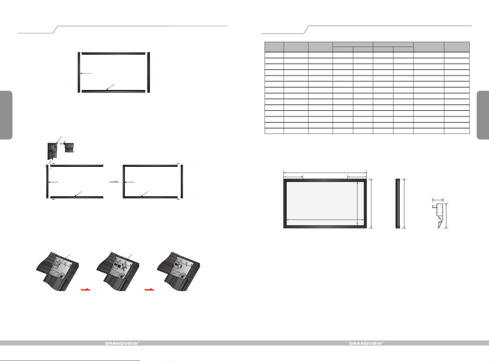
1. Lay the two side bars and two concave bars on a horizontal ground, building the shape of a rectangle. ( Figure 1 )
Side frame
Concave frame
Figure 1
2
2. Conect the axis of the corner piece of the concave frame bar to the side bar's location hole. ( Figure 2-3 )
Location hole
Axis of the corner piece
Side frame
Concave frame
Side frame
Concave frame
Figure 2 Figure 3
3. Fasten the M 8 x 30 mm corner connector screws to the corner connector screw holes. ( Figure 4-6 ). Do the same
for the rest three corner pieces.
Net weight
(kg)
7.3
8.8
9.5
12.2
13.2
18.5
9.4
9.8
11.3
12.2
12.7
13.5
14.2
17.8
Format Model
4:3
LF-PH60
LF-PH72
LF-PH80
LF-PH100
LF-PH120
LF-PH150
16:9
LF-PH77
LF-PH80
LF-PH92
LF-PH100
LF-PH106
LF-PH112
LF-PH120
LF-PH150
Specification
(In)
60 "
7 2"
8 0"
100"
120 "
150"
77 "
80 "
92 "
100 "
106 "
1 12"
120"
150"
Viewing area
W (mm ) L (mm ) H (mm) A (m m)
1219
1463
1626
2032
2438
3048
1704
1771
2037
2214
2346
2479
2656
3320
914
1097
1219
1524
1829
2286
958
996
1145
1245
1319
1394
1494
1867
Screen dimension
1381
1625
1788
2194
2600
3210
1868
1935
2201
2378
2510
2643
2820
3484
1076
1259
1381
1686
1991
2448
1120
1158
1307
1407
1481
1556
1656
2029
Bracket margin
C (mm)
360
480
490
620
730
900
490
523
581
670
660
727
740
922
Note: Sizes and specifications are subject to change at any time. Refer to real product for exact data. The tolerance
for L is ± 5mm.
C C
L
W
Front view
35mm
H
A
Side view
A
80mm
Frame section view
7
Corner piece screw hole
Corner piece
M8 x 30 mm corner
connector screws
Figure 4 Figure 5 Figure 6
Page 5
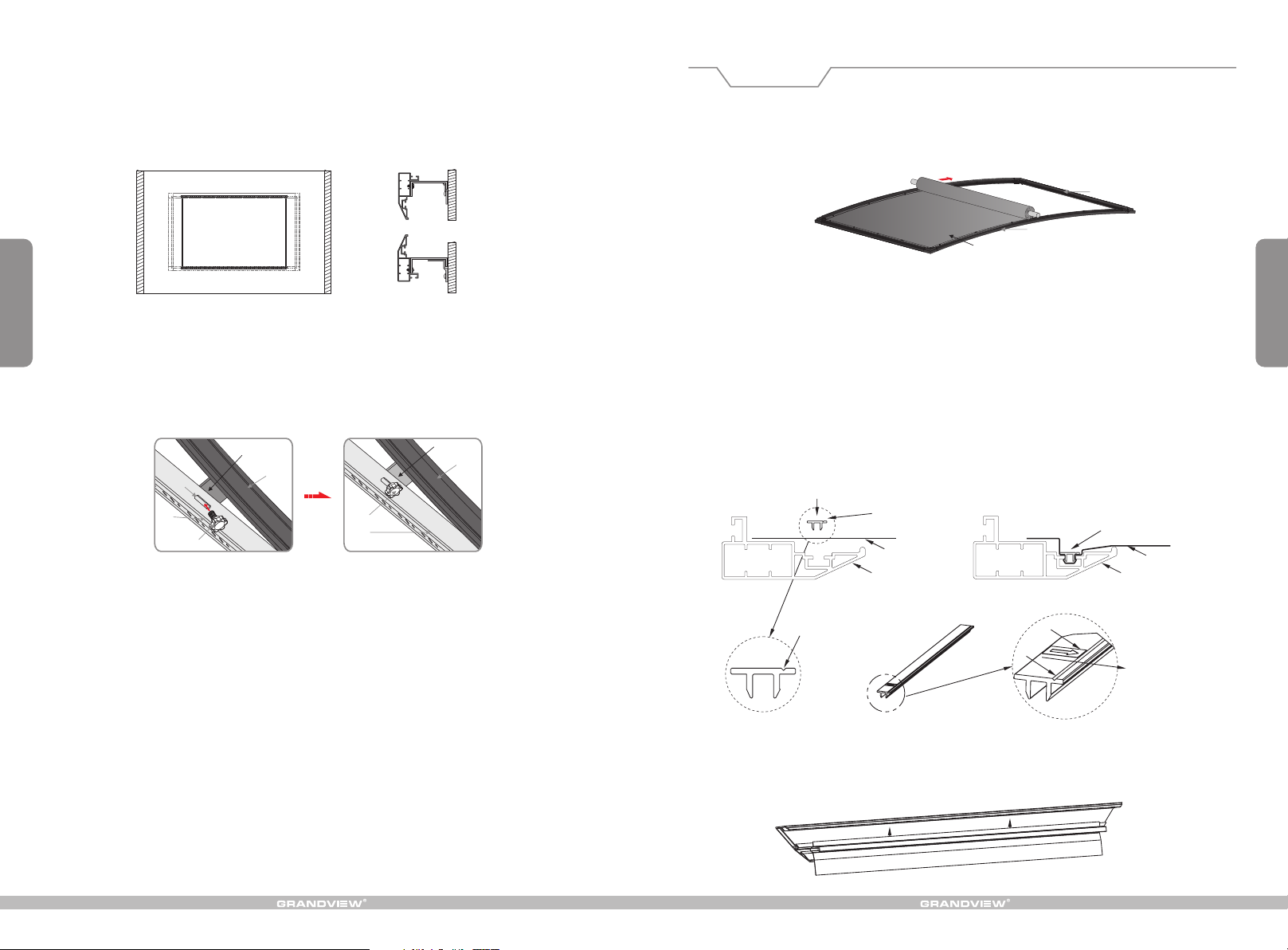
4. 14-15 )Fasten the concave bar brackets to the on-wall top and down installation bar slots. ( Figure
Installation
Turn over frame with its back upward, set it on clean desktop or ground, expand fabric per
1.
below instruction and lay on the frame, and moving the fabric to ensure it is located in the centre
of the frame. (note: When fabric facade face downward,please be careful not to scratch it.)
Side frame
Concave frame
Back side fabric
Figure 7
6
Figure 14 Figure 15
5. When the screen is installed on the installation bars, adjust the orientation of the screen to make sure the hole in the
bracket is aimed at the fixed slot in the bottom installation bar. Fasten the security screw to the hole and fix the screen.
( Figure 16-17 )
Bracket
Concave frame
Fix
e
d
s
l
ot
Bottom
installation bar
Security screw
Bracket
Concave frame
Security screw
Bottom
installation bar
Figure 16 Figure 17
2. Push down PVC stripe along the frame slot,lock down PVC stripe with slot tightly.
Note:
A. PVC stripe has directivity, the side has V slot or arrow direction must face the view area,
as per below diagram.
B. When push down the stripe, press the long side tightly first(press from the middle to the end),
and strain the fabric at the other end,then press the other long side down tightly.
C. The press the short side stripe down tightly by the same way.
D. When finish, if there is wrinkles in the view area, the user can loosen PVC strip and make the
necessary adjustment accordingly.
Push down
3. E ffe ct C lar t
PVC strip
inside of screen
(view area)
Fabric
Frame
V slot
The user can lo osen PVC strip along the outs ide directio n of
screen and adjust the flatn ess of fabric accordingly.
Push down and lock tightly
arrow direction
V slot
inside of screen
(view area)
Fabric
Frame
V slot or arrow d irection
must face the in side of
screen(view area)
3
Page 6
Screen Installation
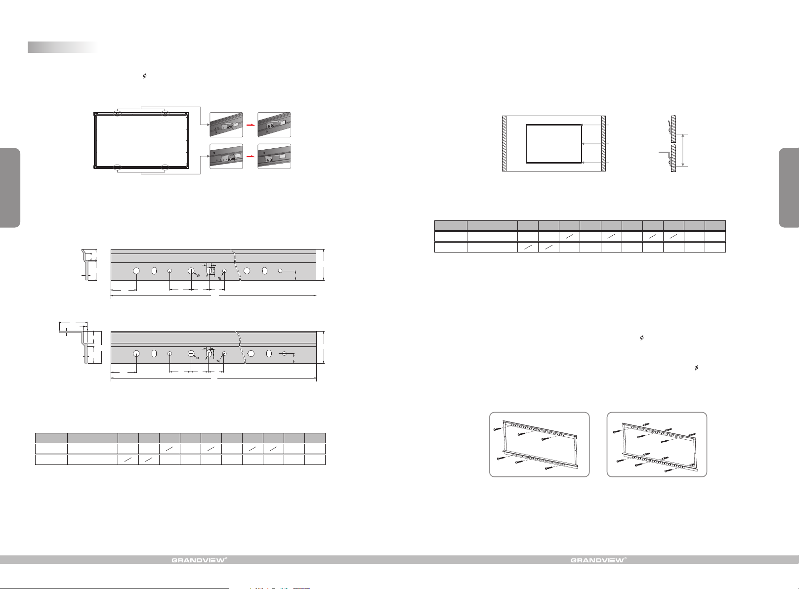
1. Each screen is equipped with 4 brackets labelled 1,2,3,4; and thus the concave frame has relevant marks of 1, 2, 3, 4.
When installing the brackets, use the 5 x10mm screws to fix the bracket 1 to mark 1 on the concave frame. Do the
same for bracket 2 , 3 and 4 . ( Figure 8 ). Make sure the screws are tightly fastened.
4
# # #
Figure 8
# #
2. Each screen is equipped with a top and bottom installation bars with many sets of holes, three of which belonging to
one set. Installation bar specifications on Figure 9.
Top installation bar
15
35
2
10
3
Side view
5
3
Side view
25
120
32 23
Bottom installation bar
15
40
21
120
32 23
8
R
Front view
8
R
Front view
6
5
6
20
Lt
6
5
6
20
Lt
12
12
Measure unit: mm
Figure 9
3. The top and bottom installation bars have been linked in factory and the length in between is pre-set. Fix the top
installation bar at horizontal level and the bottom bar will go parallel as a result of gravity. Make sure the length in
between is conform to the table 2 .Micro adjustment is allowed. Then fix the bottom installation bar. You can also
refer to table 3 for the required distance between the installation bars. ( Figure 10-11 )
top installation bar
Link
Bottom installation bar
Figure 10 Figure 11
Distance between
installation bars
5
Table 3: Distance between installation bars
Specification (in)
Format
Distance (mm)
4:3
Distance (mm)
16:9
40
Note: Sizes and specifications are subject to change at any time. Refer to real product for exact data.
72" 77" 80"
60"
1019 1202
1063
92"
1324
1101 1250
100"
1629
1350
106"
1424
112" 12 0"
1934
1499 1599
150"
2391
1972
Installation details:
a. Woody wall installation: Follow the screen installation step 3 and fix the 5 x 40 mm tapping screws to the holes in the
40
top and down installation bars, three screws on each bar. ( Figure 12 )
b. Concrete wall installation: Follow the screen installation step 3 and drill six proper holes through the concrete wall
with electrical drill, and then nail the screw anchors into the done holes on the wall. Fix the 5 x 40 mm tapping screws
to the holes on the wall through the holes in the top and bottom installation bars, three sets of screws on each bar.
( Figure 13 )
Table2: Length of installation bars ( Lt )
Specification (in)
Format
4:3
16:9
Lt (m m)
Lt (m m)
60"
72" 77"
80"
850 850 1000
1000 1000
92" 10 0" 106"
1150
1150 1150
1300 1300
112" 12 0"
1300
1450
150"
1600
1750
Note: Sizes and specifications are subject to change at any time. Refer to real product for exact data.
Figure 12 Figure 13
 Loading...