

Page 1
GRANDVIEW REPRODUCING GENUINE COLORS
GRANDVIEW REPRODUCING GENUINE COLORS
Installation Guide for
Large-flat Series Prestige Permanent Cinema Screen
Grandview Crystal Screen Canada Ltd.
#11- 3751 North Fraser Way,
Marine Way Business Centre,
Burnaby, BC, Canada V5J 5G4
Tel: 1-604-412-9777 Fax: 1-604-412-9796
Website: www.grandviewscreen.ca
Guangzhou Grandview Crystal Screen Co., Ltd.
P.O. 511400 Federal Ind. Zone No. 363, Yushan West Road,
Shiqiao, Panyu District, Guangzhou, Guangdong, China
Tel: +8620-8489-9499 Fax: +8620-8480-3343
Website: www.grandviewscreen.com
www.grandviewscreen.com.cn
ISO9001:2000
International Certification
Model:LF-PUxx(DY)
Tha nk y ou f or purc ha sing a Gr an dview p ro jecti on s creen .
Befor e us e, plea se r ead ins tr uctio ns c arefu ll y. Afte r in stall at ion, st or e instr uc tions f or f uture r ef erenc e.
Page 2
1
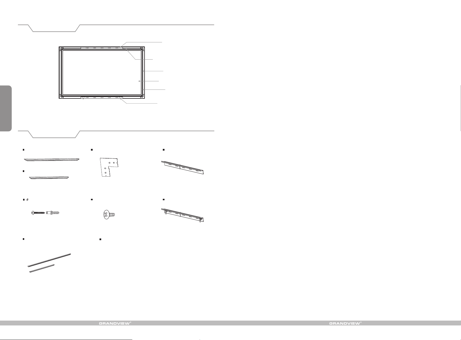
Description
Top bracket
Horizontal frame
Side frame
Screen fabric
PVC strip
Bottom bracket
Accessories
Horizontal frame (2pcs)
Side frame (2 )pcs
5x40 mm Tapping screw
with anchor (8 pcs)
PVC strip
(long/ short/ )2pcs、 2pcs
Corner br ac ke t (4 )pcs
5x10mm Co rn er s cr ew ( 16 )pcs
Instruction manual 1( pc)
Top bracket(1pc)
Bottom bracket (1pc)
Page 3
Installation
Take out al l the parts fr om the packa ging and fol low the acce ssories gu ideline to e nsure you ha ve all parts ,
then install the screen as below.
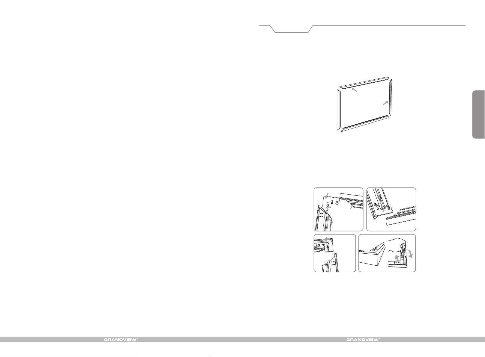
1. Locate Horizontal frames and Side frames on tidy flat surface. (Figure 1)
Horizontal f rame
Side frame
Figure 1
2. Connect Horizontal frame and Side frame with Corner bracket, adjust the Corner bracket to match screw
holes on frame and Corner backet, then fix with the Corner bracket screws. Same way to other 3 Corner
brackets installtion. (Figure 2-5)
Cor ner
2
Horizontal frame
Side frame
Figure 2 Figure 3
Figure 4
Figure 5
Page 4
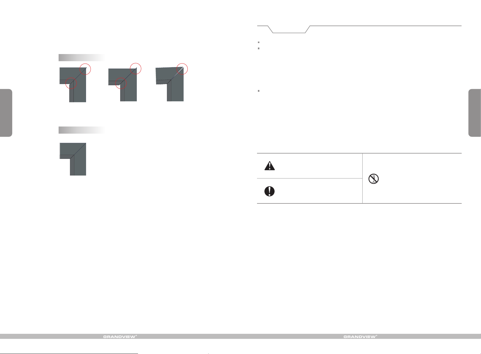
3. Check the 4 corners to ensure the Horizontal and Vertical frame connect perfectly, inc orre ct con nect ion
would effec t the fl atne ss of fa bric ,pls t ake do wn cor ner br acke ts fir st whe n inco rrec t conn ecti on, th en
adjust brackets position until all are in correct connection.
in cor re ct c on nec ti on
Figure 6 Figure 7 Figure 8
3
co rre ct c on ne cti on
Warnings
When installing, make sure it is facing forward. The ba ck of th e scre en wil l be lab eled with a sticker.
Please read the following as any damage to the screen surface will affect the quality of the picture:
1.The frame is made with lightweight aluminum. Please handle with care.
2.Avoi d cont act or t ouch ing th e scre en sur face a s it may c ause s crat ches o r tear s.
3.Do not write or draw on the surface.
4.Clean the screen with a soft cloth and lukewarm water. Do not use any detergent or cleaning products.
5.Use a cotton cloth to carefully wipe off the d ust on t he fra me to pr even t any da mage s
6.If it is not in use for a long period of time, cover the screen to shut out dust and dirt.
To prevent unne cessary dama ge, the operatin g and maintenanc e of the screen should be done by adults .
Opening the case, the frame has indentations on surface because of packaging in a dry case for a long
time. This is a n orma l phen omen on and t he scr een ca n be use d normally. Please stay the screen in a
normal condition that the indentations can be naturally removed. Recovery time will be changed in 1-15
days because of the air humidity, If you wa nt to re move t hese i nden tati ons qu ickl y, please use half-wet
solution.
Methods: Sprinkle water on the surface that can remove the indentations.
8
Figure 9
Ignoring the safety warnings may
le ad t o in jur ie s an d/o r damaging
the product.
Fixtures should be installed in a secure
place to avoid accidents or the screen
falling.
Do not take apart and replace with unknown parts. If there are any problems, please contact your local dealer.
Product specifications are subject to change.
Please contact your local dealer for
repairs or maintenance. Please contact
our company if yo u have any further
questions. Av oi d t ak in g a pa rt th e
fixtures yourself. Loose parts may
cause the screen to fall.
Page 5
7
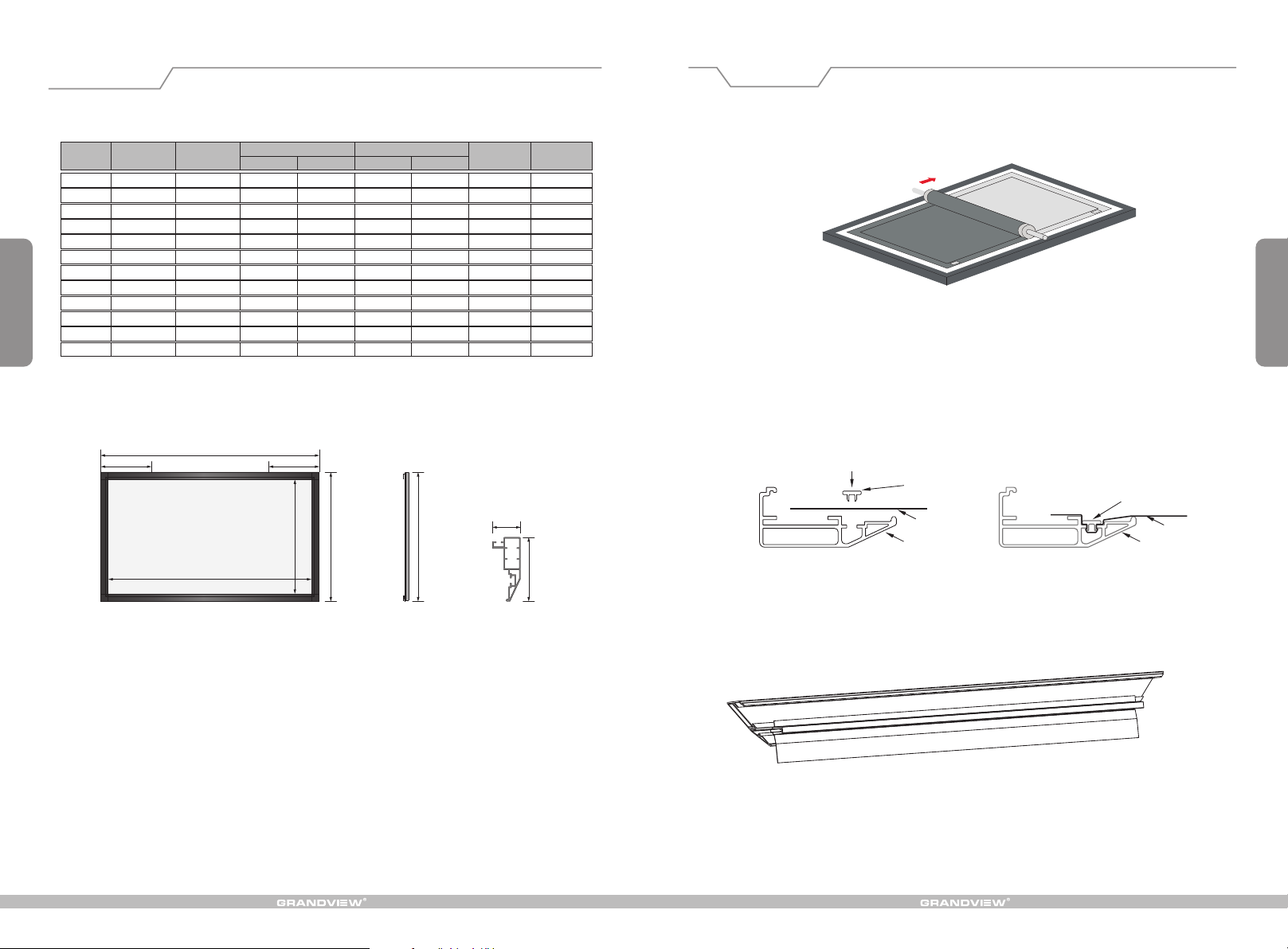
Specifications
Format Model
4:3
LF-PU100
LF-P 120 U
LF-P 150 U
LF-P 180 U
16:9 92 "
LF-P 92 U
LF-P 100 U
LF-P 106 U
LF-P 120 U
2.35:1 LF-P 103 U
LF-P 150 U
LF-P 115 U
LF-P 125 U
Specification
(In)
100"
120 "
150"
1 08 "
100 "
106 "
120"
150"
103"
115"
125"
Viewing area
W (mm ) H (mm ) L (mm )
2032
2438
3048
3658
2037
2214
2346
2656
3320
2407 1025
2687 1145
2921 1245
1524
1829
2286
2743
1145
1245
1319
1494
1867
Screen dimension
2194
2600
3210
3820
2201
2378
2510
2820
3484
2569 1187
2849
3083
A (mm)
1686
1991
2448
2905
1307
1407
1481
1656
2029
1307
1407
Bracket
margin C (mm)
500
600
700
900
500
500
600
600
800
600
600
700
Note: Sizes and specifications are subject to change at any time. Refer to real product for exact data. The tolerance
for L is ± 5mm.
Net weight
(kg)
12.3
14.7
18.5
22.6
11.0
11.9
12.5
14.2
15.5
12.6
13.1
14.0
Installation
Turn over frame with its back upward, set it on clean desktop or ground, expand fabric per
1.
below instruction and lay on the frame, and moving the fabric to ensure it is located in the centre
of the frame. (note: When fabric facade face downward,please be careful not to scratch it.)
Figure 10
Push down PVC strip along the frame slot, connect fabric with frame and lock down PVC strip tightly.
2.
(Remark: when installing the fabric, pls follow to push down the long PVC strip firstly, and strain the fabric in
the other end and push down the other long PVC strip. when it's done, follow the same way to push down
the short PVC strip on the frame.)
4
C C
L
W
Front view
Push down
PVC strip
35mm
H
A
Side view
A
80mm
Frame section view
3. E ffe ct C lar t
Fabric
Frame
Push down and lock tightly
Fabric
Frame
Page 6
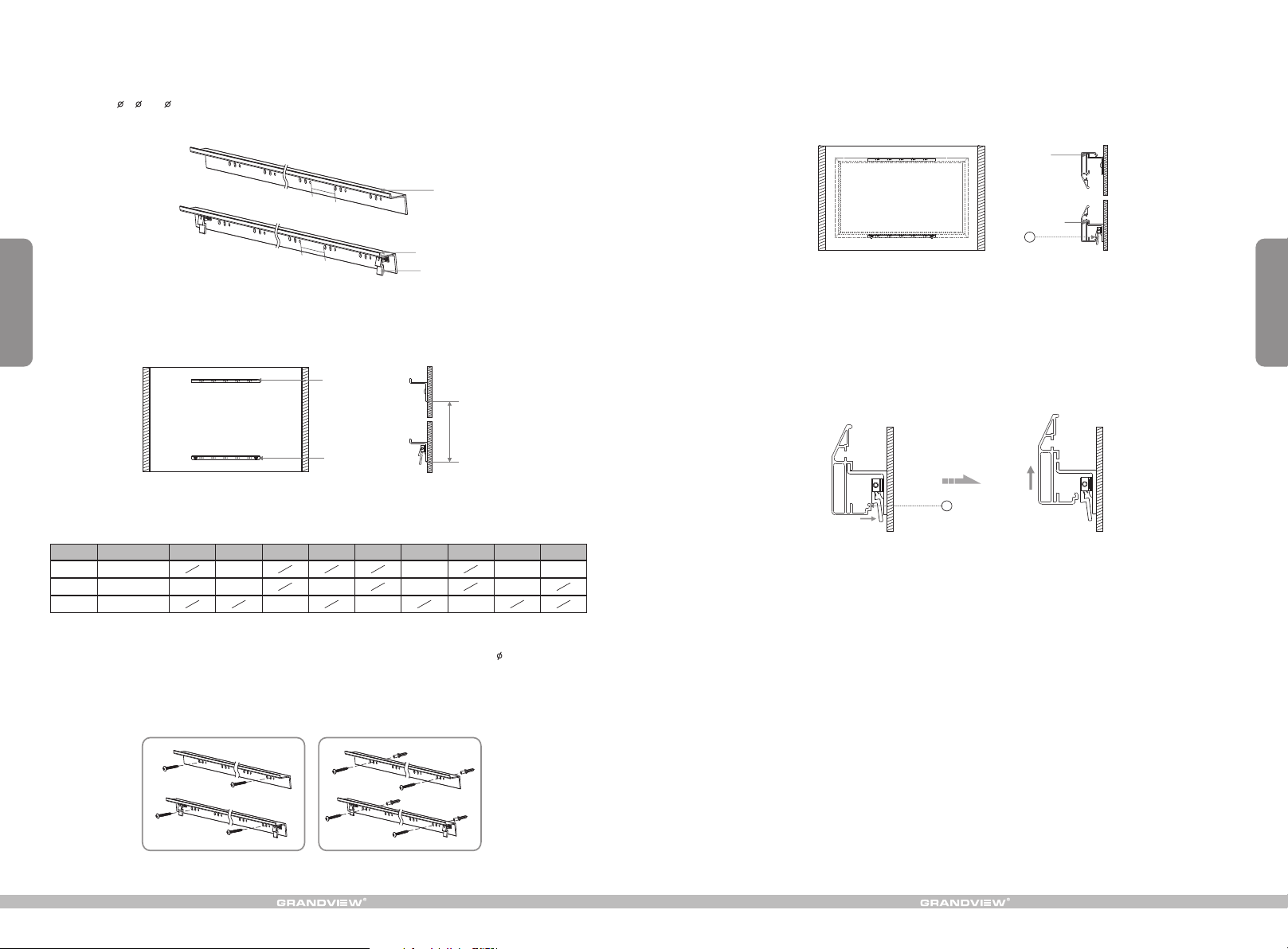
4. There is locking system on the Bottom bracket but no on the Top backet, brackets' length are at half of
Horizontal frames'. And there is 5 groups of holes on each brackets with 10cm distance, each group has
3 holes at 5 8 & 6 from left to right. Brackets are suggested to mount at the middle point of frame with
only 30% fluctuation if needed. (Figure 11)
6. Uplift the assembled screen to make sure Up groove meet with Top bracket, and Down groove meet with
Bottom bracket, the Secure button would lock into Groove B because of spring tension when frames are
matched on brackets ideally. (Figure 16-17)
Up groove
10
CM
10CM
Figure 11
5. According to AA distance list on first page, mount two brackets onto the wall separately, assure they are at
5
Up bracket
Bottom bracket
Secure button
horizontal level. (Figure 12-13)
Up b rac ke t
AA
Bo tto m br ac ket
Figure 12 Figure 13
List II: The distance between top bracket A and bottom bracket A(AA):
106"
1430
115" 125"120"
1940
1605
1256 1356 1136
Rat io
4:3
16:9
2.3 5: 1
Siz e
AA( mm )
AA( mm )
AA( mm )
92"
1256
100"
1635
1356
103"
Here below are the mounting details:
a) Wood wall mounting: to fix the brackets onto the wall using 4 provided Wooden screws 5 x 40, two screws
for each brakcet. (Figure 14)
b) Concrete wall mounting: to use an electric drill to drill 4 holes ( 2 holes for each bracket), and hammer the
provided tapping anchors into each hole, then fix the brackets onto the wall by fastening the tapping screws
to the tapping anchors. (Figure 15)
150"
2397
1978
180"
2854
Bottom groove
B
Figure 16 Figure 17
6
7. To tear down the screen, please press the Secure buttons towards wall to release bottom frame from
groove B, then uplift the screen little to release it totally from up groove & bottom groove of the brackets.
(Figure 18-19)
B
Figure 18 Figure 19
Figure 14 Figure 15
 Loading...