

Page 1
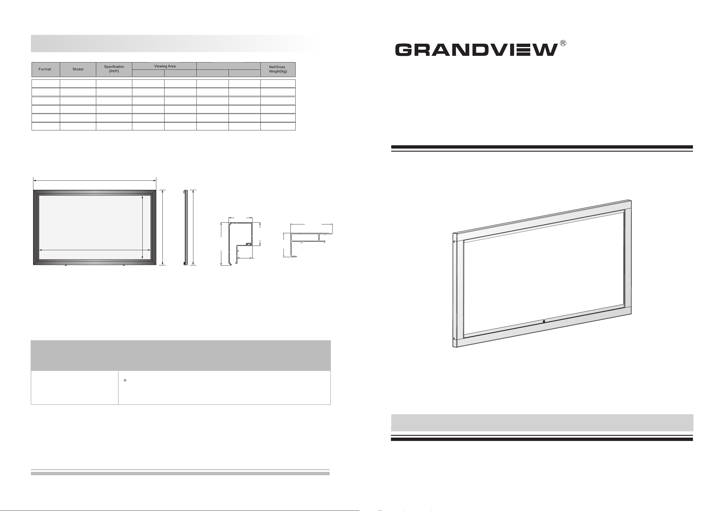
Product Specification
Scree n Siz e
W (mm) L (mm) H (mm) A (m m)
16:9 77 "
Note:
1. Due to product updates, sizes and specifications are subject to change at any time. The tolerance for L is approximately ± 5mm (3/16 inches).
2. Actual dimension is measured by: total screen length x end cap depth x end cap height.
VMF
LF- -77
VMF
LF- -80
VMF
LF- -92
VMF
LF- -100
VMF
LF- -106
VMF
LF- -120
L
80 "
92 "
100"
106”
120”
W
1705
1771
2037
2214
2346
2656
H
958
996
1145
1245
1320
1494
A
1915
1981
2247
2424
2556
2866
A
110mm
1258
1296
1445
1545
1620
1794
60mm
60mm
REPRODUCING GENUINE COLORS
Instruction Manual for
Large-Flat Series Adjustable Fixed-Frame Screen
105mm
60mm
38.5m m
Fron t Vi ew
Ques tions & Answers
Fabr ics of Gr andview s creen c an be used for years , most problems ar e caused by simple i ncide nts. If pro blem
occu rs, ple ase find th e list be low for some commo n solutions. If pr oblems keep on, pl ease co ntact aut horiz ed
agen t of Gran dview or ca ll serv ice number at: (86 20)34806166
Wrinkl e on the fr ame
When u sing no rmally, the wr inkle c an be remov ed natu rally. The remov ing
peri od will c hange with 1-15d ays according to t he temperature . Wate ring
can re move th e wrinkle f aster.
Side Vie w
Concav e Fr am e
Bar Side View
Side Fra me B ar
Side View
Three years warranty
Gran dview p rovides t hree ye ars warranty. Conte nts of warr anty in clude replacem ent of spare parts w hile problems
occu r with co rrect ope ratio n. Not include ina ppropriately o perating the scr een or un install t he scre en by yours elf.
You should re serve in advance f or the repair with G randv iew or appo inted s ervice ce nter.
Model: VMF-xxxLF-
Thank you for purchasing a Grandview projection screen.
Before use, please read instructions carefully. After installation, store instructions for future reference.
7
Page 2
Caution
Warnings:
1. Ple ase rea d careful ly with t his instructio ns before instal lation to avoid th e damag e caused by i nappr opriate
inst allat ion or oper ation
2. Ple ase kee p the scree n away fr om hot sources, su ch as radiator, hea ting machine, fi repla ce, louds peake r
or oth er rela tive devi ce.
3. Ple ase han dle the rep air wor k to the professio nal agent
4. Ple ase pre vent scre en from w ater as wel l as putt ing stuff wit h water ( such as vase) on the s creen.
please prevent scree n from wet place to avoid electr ic or fire danger
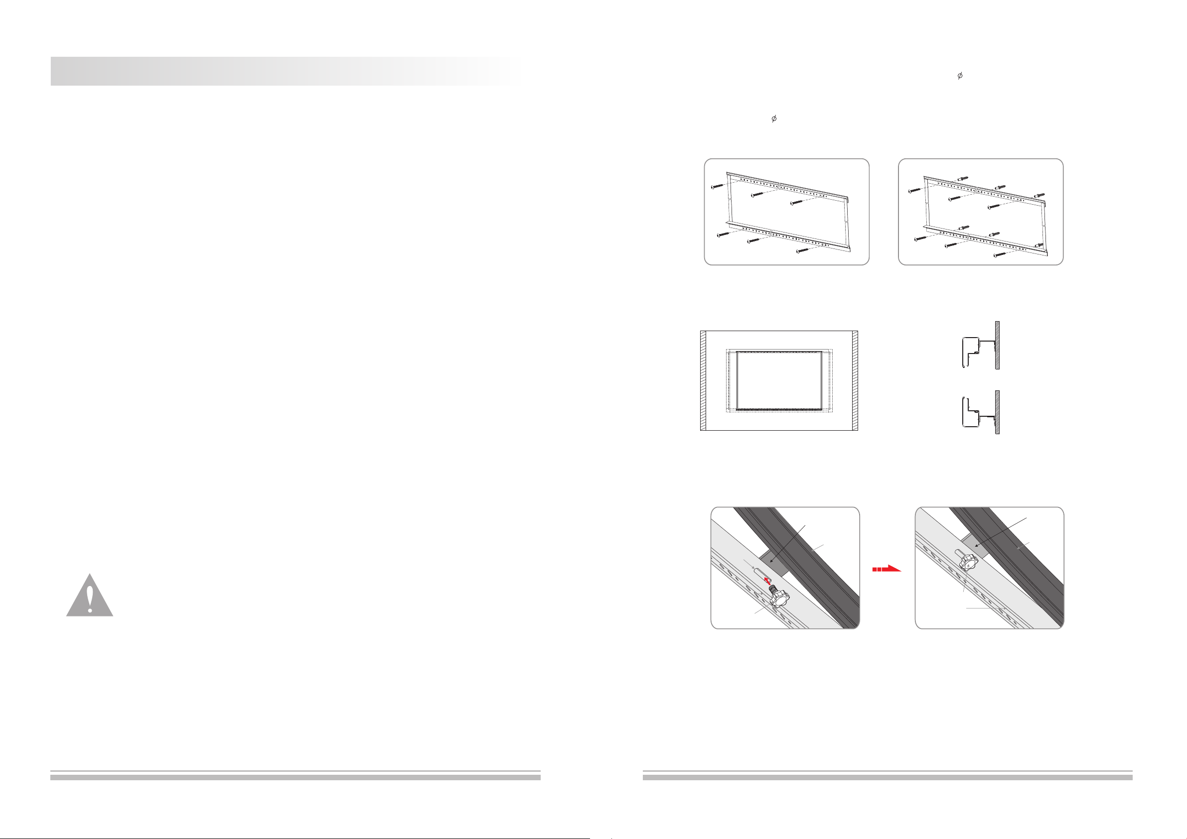
Plea se foll ow the inst allat ion as below:
a.Wood wa ll inst allatio n: fix th e top and low b racke t on the wall u sing th e 5X60mm wood scre w (3 screws on
each b racke t) (figur e 11) .
b.Con crete w all insta llati on: drill six prop er holes on the conc rete wa ll with ele ctric d rill, the n fix the t op and low
brac ket on th e wall usin g the 5X4 0mm tappi ng scre w and then fasten wi th the anchor (3 scr ews on each bracke t)
(fig ure 12) .
5. Ple ase mak e sure whic h one is fr ont or back of produ ct.
6. Ple ase put d own the scr een car efully because o f the aluminum all oy frame.
7. Ple ase cov er the scre en by clo th if it is not b eing us ed for a long time.
8. Ple ase do no t poke scre en fabr ic with hand or edge t ools to avoid mark ing on the screen su rface .
figure 11 figure 1 2
3.Buc kle the h anger of co ncave f rame bar on top and lo w bracket, figur e 13-14.
figure 1 3 figure 1 4
4.Aft er hang ing on the br acket , please adjust th e screen horizon tally and ensure t he hole o f hanging p iece an d the
hole s of low br acket is at t he same l evel, and t hen fas ten the security f ixing screws int o the holes (figur e 15-16 )
Hanging Piece
G
r
oov
e
Frame
Hanging Piece
Frame
Plea se foll ow the inst ructi on to operate.
Plea se cont act the pro fessi onal people for re pairing.
Cleaning
Clea n the cas ing of scre en with a s oft cloth a nd luke warm water.
Do not u se any de tergent o r clean ing products.
1
Top Bracket
Security Fixing Screw
figure 1 5 figure 1 6
Security Fixing Screw
Low Bracket
6
Page 3
Screen Installation
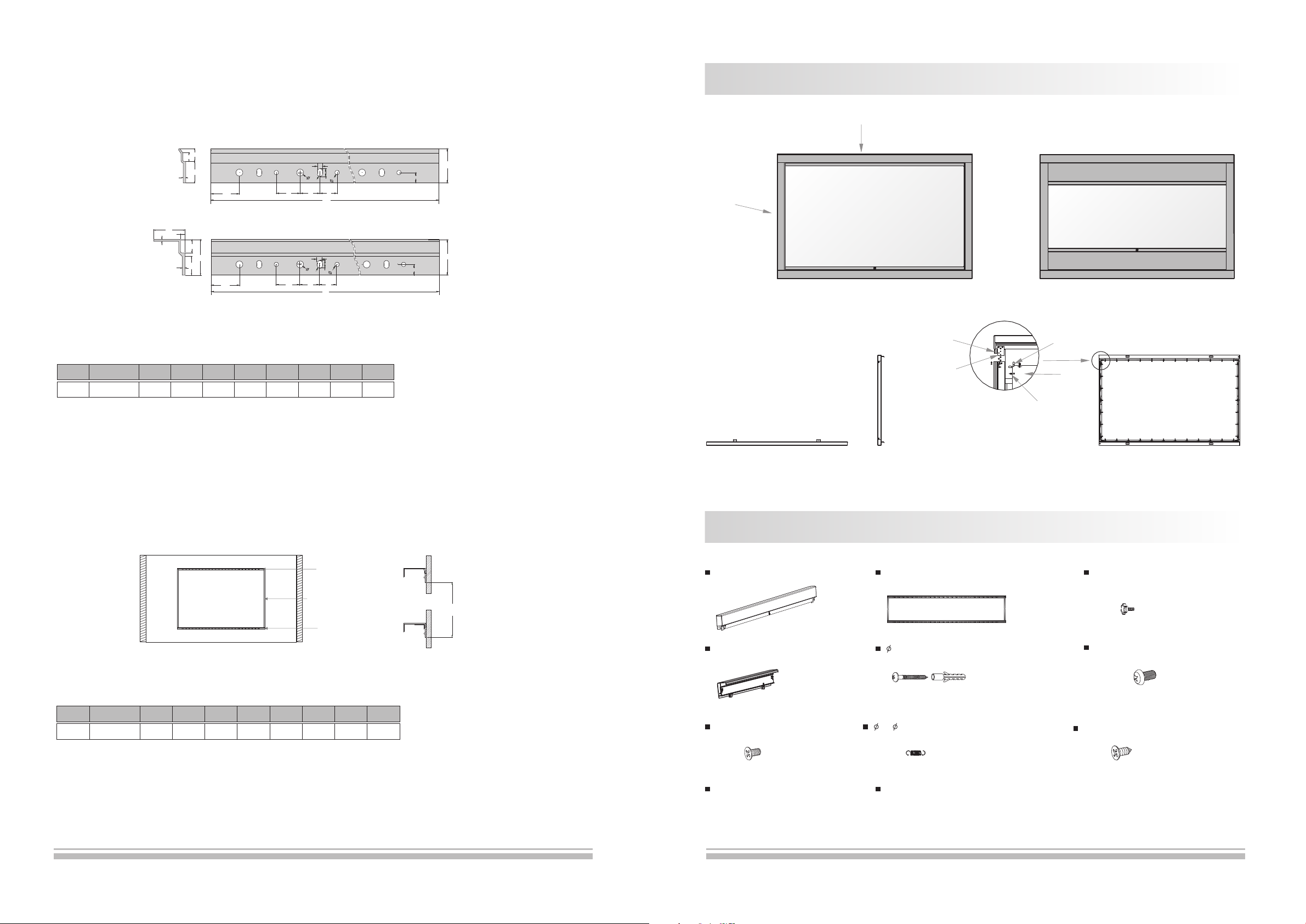
1.Eac h scree n has a set of br acket . Each brac ket has a n umber of corresp onding holes and 3 h oles pe r group,
Plea se refe r to figure 8 .
Top Bracket
15
10
25
3
Side View
35
2
5
3
6
8
5
6
R
120
32 23
20
Lt
Front View
Low Bracket
15
40
21
120
32 23
6
8
5
6
R
20
Lt
Front ViewSide View
12
unit:mm
40
12
40
Description
Side Fra me B ar
Concav e Fr am e Ba r
幕布
Front View(16:9)
Front View(2.35:1)
figure 8
Table 2: the length of bracket (Lt)
Spec ific atio n
Form at
Lt (mm )
16:9
1000 1000
Note: due to produ ct u pd ates, sizes and specifications ar e su bj ect to change at any time.
77"
80"
92" 100" 106"
1150 1150
112" 120"
1300 1300
1450
150"
1750
2.Top bra cket an d low brack et are co nnected by a belt wh en delivery. The t op brac ket shall k eep bal ance with the
low br acket v ertical ly beca use of the univers al gravitation . Please ensure th e dista nce betwe en the to p bracket
and th e low bra cket is the s ame as th e data of tab le show s us (if not, please m easure), and the n fix the frames on
the wa ll ( plea se refer th e data to m ake sure th e dista nce between top an d low bracket) (fi gure 9- 10)
Top Bracke t
Link
1489
Low Brac ke t
Top View
Accessories
Co n cave Fra me B a r (2p cs)
Connec ti ng B oa rd 1
Connec ti ng B oa rd 2
Side View
Top& L ow Br acke t (1 pc)
Rod
Spring
Screen
Screen
Back View
Secu rity Fi xing Scre w (2pcs )
Table 3: the safety distance between two brackets
Spec if ic atio n
Format
Distance(mm)
16:9
Note: due to product updates, sizes and specifications are subject to change at any time.
77" 80"
1063
1101 1250
92"
100"
1350
106"
1424
112" 1 20 "
1499 1599
figure 9 figure 1 0
5
150"
1972
Si d e Fr ame B ar (2 pcs)
M4X6 mm Scre w(8pcs)
In s truc tion M a nual ( 1 pc)
5×40 mmTappin g wi t h Anch or(8se ts)
7x 0.8x 28mm Spri ng(A num b er)
Warra nty C ard (1pc )
2
M5X8 mmScr ew 1 2pcs( )
M2.5 X8mmTap ping Scre w(4pcs)
Page 4
Installation
Screen Fabric Installation
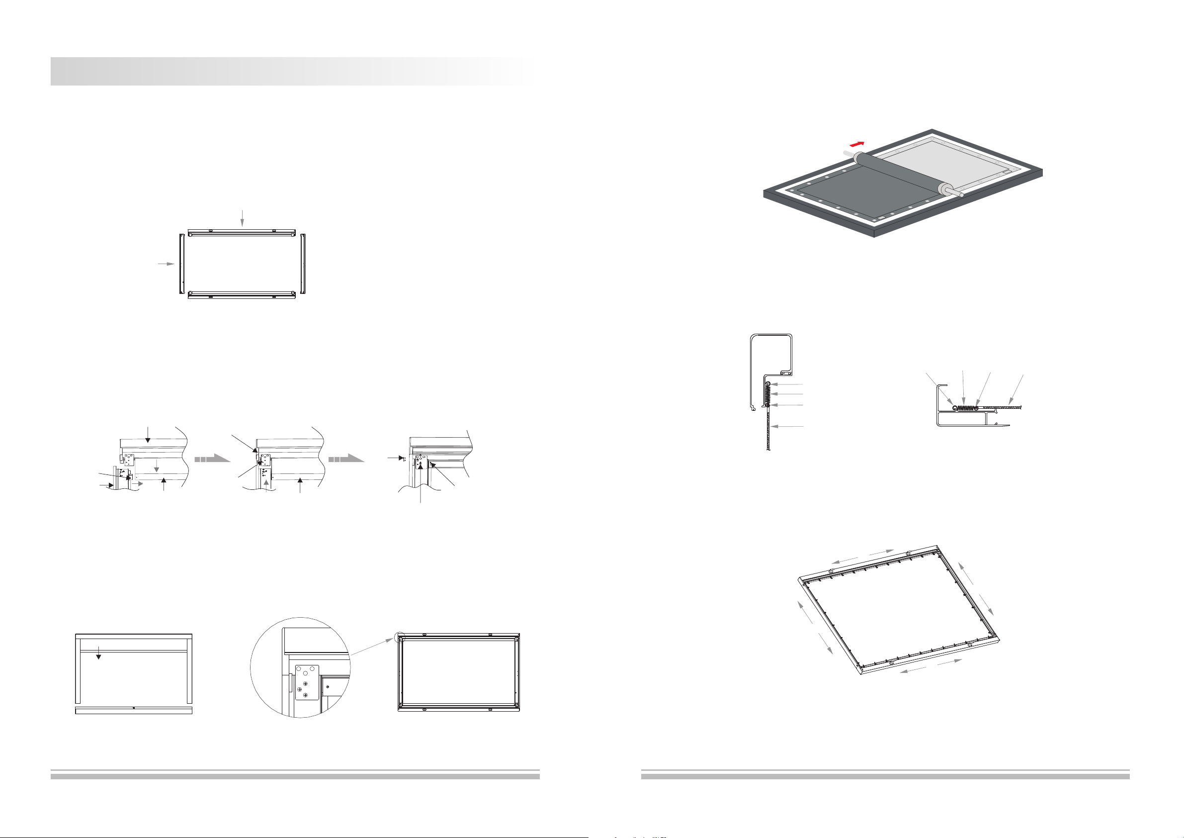
Open t he pack ing box, ch eck whe ther the co mpone nts which need to be i nstalled are com plete o r not accor ding to
the Acc essor y Diagram matic S ketch in th e user ma nual, then take ou t all the small comp onent s careful ly from t he
pack ing box a nd put them a t a suita ble place, final ly install it acco rding to the opera ting me thod as bel ow:
Frame Installation
1.Put t he fixi ng lug into t he slot s of top and bo ttom ba rs, taking the fol lowing table as re ference (figur e 1).
Concav e Fr am e Ba r
Side Fra me B ar
figure 1
1.Pul l up the to p bar to a suit able di stance in order to a ttach the bar plug i nto it. And then inse rt the connectin g
boar d 1 and the c onnecti ng boar d 2 into Side Frame Ba r (please operat e together in two si des). F inally, fast en
the co rresp onding sc rews: f igure 2
Concav e Fr am e Ba r
Connec ti ng B oa rd 1
M4X6mm
Screw
1.Pu t the who le frame up side do wn and then unwrap t he screen fabric ( avoid scraping t he fabr ic when
unwr appin g) (figur e 4).
figure 4
2.Put t he tens ion bars to t he four s lots of scr een fab ric (note : this is a s tep suggested to b e completed by two
pers ons, on e to hold the s creen f abric and the othe r pull through the t ension bar) (fig ure 5-7 ).
Positi on f or
Frame Ha ng er
Positi on f or F ra me H anger
Spring
Rod
Screen F ab ri c
Spring
Screen F ab ri c
Rod
Plug
Side Fra me
Bar
Top Bar
Connec ti ng
Board 2
Top Bar
figure 2
M2.5x8 mm
Tapping Sc re w
M5x8mm Sc re w
3.The i nstal lation of l ow bar is t he same as to p bar. Not ice: please pull u p the top bar to a suita ble dis tance and k eep
it wh en o per atin g t his ste p, othe rwi se, the lo w b ar can not be pu lled ou t, and the n t he inst alla tio n i s c ompl eted
(fig ure 3).
Pul l up the to p bar
figure 3
Instal la ti on f or s pring of concave frame bar
figure 5
Instal la ti on f or s pring of side frame bar
figure 6
figure 7
3
4
 Loading...