

Fresh Indoor Air Quality
R
570 SERIES
INSTALLER: PLEASE FILL OUT AND MAIL WARRANTY CARD AFTER INSTALLATION IS
COMPLETE. LEAVE INSTALLATION INSTRUCTIONS WITH HOME OWNER
PRECAUTION: The installer should be an experienced service technician. Disconnect electrical power before
beginning installation. Do not install where temperatures fall below 32 degrees F or where plenum temperatures
exceed 150 degrees F. When wiring into a multi-speed blower circuit see Step 6.
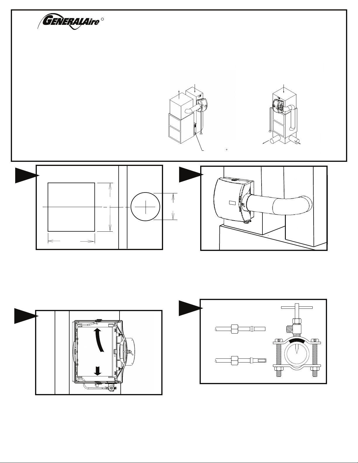
INSTALLATION: The humidifier may be mounted with the 6" outlet to
the right or left by inverting the cabinet and reversing the positions of
the distributor trough and drain pan. The humidifier may be mounted
on the warm or return air plenum with equal efficiency.
See Typical Installations.
ADDITIONAL MATERIALS THAT MAY BE NECESSARY:
1. 1/4" diameter plastic supply tubing or 1/4" copper
supply tubing for hot water applications
2. 6" diameter galvanized by-pass pipe
3. electrical wire and wire nuts
4. current sensing relay (G.F. Model #GA50 suggested)
5. #8 self piercing sheet metal screws
1
WARM AIR
UP FLOW
3
3
RETURN AIR
DRAIN
GENERALAire AC SERIES
HIGH EFFICIENCY AIR CLEANER
R
WARM AIR
9-1/2”
6”
FLOW-THROUGH
BYPASS HUMIDIFIER
FOR INSTALLATION ON A VERTICAL
PLENUM SURFACE OF ANY
FORCED AIR FURNACE
RETURN AIR
DRAIN
DOWN FLOW
WARM AIR
8-7/8”
The General Aire model 570 may be installed on either the
supply or return plenum of a forced air handling system. Select
a location for the humidifier that allows for service and
maintenance. Cut out a rectangle 8-7/8” wide by 9-1/2“ tall.
Extend horizontal centerline of cut out to the adjacent plenum.
Cut a 6” hole 10” to 15” from side of humidifier, on cabinet
centerline, using connecting collar as guide. The bypass is
reversible and can be mounted on the right or left side of the
humidifier.
2
1
Humidifier is self retaining. Slide top side in first, then slide
chassis down. Level chassis and install center screws. If
by-pass pipe installs to opposite side of chassis, bend clip on
chassis, remove side discharge, and reinstall discharge to
opposite side of chassis. Install remaining four corner screws.
FORM NO. 570-18 (FILE 15018) REV. E
Connect by-pass pipe to collar and humidifier cabinet. Using
holes at top and bottom of side panel discharge, pierce 2
self tapping screws through by-pass pipe.
4
COPPER
TUBING
PLASTIC
TUBING
2
Mount the self tapping saddle valve or code valve on either a cold
or a hot water pipe. A side or top mount is best to avoid clogging
from pipe sediment. Connect 1/4” O.D. tubing to the saddle valve.
Copper tubing requires a brass compression nut and brass sleeve.
Plastic tubing requires a brass insert inside the tubing, a plastic
sleeve on the outside with a brass compression nut.
NOTE: DO NOT USE PLASTIC TUBING ON HOT WATER OR IN
CONT ACT WI TH ANY H OT PLE NUM SURFACE OR DUCT.
INSTALLATION OF THIS SADDLE VALVE MU ST MEET OR
EXCEED LOCAL CODES AND ORDINANCES.
GCV3412 CODE VALVE INSTALLATION INSTRUCTIONS
Copper Pipe
1. Turn off water supply.
2. Clean pipe, fittings and valve with sandpaper or wire brush.
3. Apply a thin layer of flux to all surfaces to be soldered.
4. Assemble valve to pipe and/or fittings.
5. Cooling the valve by wrapping a wetted rag around the valve is
optional.
6. Heat the joints with a torch. Apply solder to each joint. Continue to
apply heat sufficient to keep solder liquid.
7. After solder has filled entire joint area, remove heat and allow joint
to cool. Do not move or disturb.
8. Slide compression nut over 1/4” copper tube followed by
compression sleeve.
9. Insert tube into valve fully and tighten nut.
10. Turn on water supply and check for leaks.
*CODE VALVE IS INCLUDED WITH AUTOMATIC MODELS ONLY
3/4” TEE
1/2” TEE
5
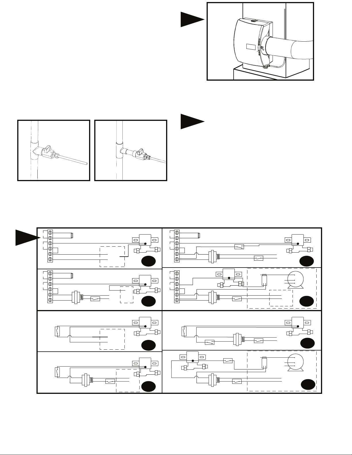
Connect 1/4" water supply tube to brass filter at inlet of solenoid. DO
NOT USE PLASTIC TUBING IN CONTACT WITH ANY HOT
PLENUM SURFACE OR DUCT. IF USING PLASTIC TUBING, USE
TUBE SUPPORT P189 AND PLASTIC COMPRESSION SLEEVE
P190.
6
Turn damper knob to winter (open) position. Turn on water
supply and check operation of humidifier. Set humidistat to a demand
setting. With the furnace off, the solenoid valve should be closed.
Start the furnace, the solenoid valve should open when the blower or
burner circuit is energized. Check flow of water through distributor
trough and evaporator pad. The standard GA4231 yellow orifice will
supply approximately 3.5 GPH of water at a line water pressure of 60
psi. For low water pressures (20-40 psi) a larger orange orifice
GA4299 is available to provide the same flow. Leave humidistat set
at the recommended setting.
7
SNSR
HUM
AC N
AC L
SNSR
HUM
AC N
AC L
HUMIDISTAT
HUMIDISTAT
OUTDOOR TEMP. SENSOR
WIRE JUMPER
WIRE JUMPER
OUTDOOR TEMP. SENSOR
WIRE
JUMPER
727-58 24 V. TRANSFORMER
24 V. TRANSFORMER
ON-OFF SWITCH
FURNACE
CONTROL BOARD
C
24v.
60CY.
R
N
115v.
(HOT)
60CY.
FURNACE
CONTROL BOARD
C
24v.
60CY.
HUM
ON-OFF SWITCH
W
W
FURNACE
BOARD
FURNACE
BOARD
(HOT)
ACC
EAC
24v.
60CY.
24V. SOLENOID VALVE
24V. SOLENOID VALVE
24V. SOLENOID VALVE
24V. SOLENOID VALVE
C
115v.
60CY.
7A
7C
7E
7G
SNSR
HUM
AC N
AC L
SNSR
HUM
AC N
AC L
HUMIDISTAT
Connect drain hose to 1/2" spout on humidifier cabinet using hose
clamp. Run 1/2" hose to suitable drain such as floor drain, sewer or
laundry sink. Be sure hose has continuous slope and is not kinked at
any point.
L2
115v.
60CY.
(HOT)
L1
FURNACE
COMMON LEAD
C
(HOT)
L2
115v.
60CY.
(HOT)
L1
FURNACE
COMMON LEAD
C
(HOT)
115v.
60CY.
24V. SOLENOID VALVE
7B
C
MULTI
SPEED
HI
BLOWER
LO
MOTOR
115v.
60CY.
7D
24V. SOLENOID VALVE
7F
C
MULTI
SPEED
HI
BLOWER
LO
MOTOR
OUTDOOR TEMP. SENSOR
WIRE
JUMPER
727-58 24 V. TRANSFORMER
24V. SOLENOID VALVE
OUTDOOR TEMP. SENSOR
WIRE
JUMPER
727-58 24 V. TRANSFORMER
C
12500 AIR
PRESSURE SWITCH
24V. SOLENOID VALVE
24 V. TRANSFORMER
NO
C
12500 AIR
PRESSURE SWITCH
ON-OFF SWITCH
24 V. TRANSFORMER
HUMIDISTAT
ON-OFF SWITCH
NO
ON-OFF SWITCH
CURRENT
SENSING
RELAY
ON-OFF SWITCH
CURRENT
SENSING
RELAY
GA50
GA50
7H
7A-7D Electronic Humidistat
7A - To furnace control board 24 volts
7B - To constant power using 24V transformer and pressure switch
7C - To furnace control board 115 volts with 24V transformer
7D - To constant power using 24V relay and current sensing relay
7E-7H Manual Humidistat
7E - To furnace control board 24 volts
7F - To constant power using 24V transformer and pressure switch
7G - To furnace control board 115 volts with 24V transformer
7H - To constant power using 24V relay and current sensing relay

570-1 CHASSIS
900-9 NOZZLE
900-10 SPOUT
GA4226 DISTRIBUTOR TUBE
PARTS LIST FOR HUMIDIFIER
570-40 PAD RAIL
GA-10 EVAPORATOR PAD
900-15 DISTRIBUTOR TROUGH
900-11 DAMPER KNOB
900-28 DAMPER DISK
570-2 SIDE PANEL
DISCHARGE
900-71 BADGE
570-13 COVER
900-14 DRAIN PAN
GA4040 SOLENOID VALVE ASM
GA4004 STAINER SCREEN
P102 COMPRESSION SLEEVE
P101 COMPRESSION NUT
P189 BRASS TUBE INSERT
747-38 TUBING KIT (AVAILABLE)
GA4231 YELLOW ORIFICE
P190 COMP. SLEEVE (PLASTIC)/P102 COMP. SLEEVE (BRASS)
P101 COMPRESSION NUT
LIMITED WARRANTY
This humidifier, if properly registered by the return of the warranty registration card to the manufacturer, is warranted to the consumer against defects in
materials and workmanship for a period of ten years from the date of installation. Evaporator pads, water strainers or metering orifices are not covered by this
limited warranty or any other warranties. Any other defective parts will be repaired without charge except for removal, reinstallation and transportation costs.
To obtain repair service under this limited warranty, the consumer must send the defective part or the complete humidifier to the manufacturer.
THERE ARE NO EXPRESS WARRANTIES COVERING THIS HUMIDIFIER OTHER THAN AS SET FORTH ABOVE, THE IMPLIED WARRANTIES OF
MERCHANTABILITY AND FITNESS FOR A PARTICULAR PURPOSE ARE EXPRESSLY EXCLUDED. THE MANUFACTURER ASSUMES NO LIABILITY IN
CONNECTION WITH THE INSTALLATION OR USE OF THIS PRODUCT, EXCEPT AS STATED IN THIS LIMITED WARRANTY. THE MANUFACTURER
WILL IN NO EVENT BE LIABLE FOR INCIDENTAL OR CONSEQUENTIAL DAMAGES.
This limited warranty gives you specific legal rights, and you may also have other rights which vary from state to state. Some states do not allow either
limitations on implied warranties, or exclusions from incidental or consequential damages, so the above exclusion and limitation may not apply to you.
Any questions pertaining to this limited warranty should be addressed to the manufacturer. (U.S.A.: The manufacturer has elected not to make available the
informal dispute settlement mechanism which is specified in the Magnuson-Moss Warranty Act.)
CARE AND MAINTENANCE
Your humidifier is engineered to give helpful and trouble-free humidification. For maximum efficiency the following cleaning procedures should be carried out at
the end of each heating season:
1. Turn off water supply and electrical power to humidifier.
2. Remove water cover, distributor trough, evaporator pad and drain pan. Clean excessive mineral deposits from the
distributor trough, drain pan, pad rails, and humidifier cabinet. A solution of 1/2 vinegar & 1/2 water will help loosen mineral
deposits.
Replace humdifier evaporator pad if necessary. (Part number GA10) Install trough and drain pan.
3.
Replace cover. Replace evaporator pad yearly for peak performace.
4. In heavy mineral areas or if the solenoid valve fails to function disconnect the 1/4” water supply line from the solenoid valve.
Carefully pull the strainer screen (P.N. GA4004) from the valve body (P.N. 900-6). Clean the mineral deposits from all
parts. If the orifice is clogged, it may be opened by inserting a small pin. Reinsert the filter into the orifice fitting and screw
the brass strainer body into the solenoid valve.
5. Reconnect the 1/4” water line to the solenoid valve if necessary. Turn on the water supply and check all points for leakage.
The operation of the unit may be checked by starting the furnace. The humidifier operates only when the furnace blower is
running or the burner circuit is energized. The humidifier is now ready for operation.
6. During the summer, turn off water supply and electrical power to humidifier. Close air damper.
AT
OUTSIDE
TEMPERATURE
-20°F -29°C
-10°F -23°C
0°F -18°C
+10°F -12°C
+20°F - 7°C
+30°F - 1°C
RECOMMENDED
SETTING
15%
20%
25%
30%
35%
40%

HOW THE HUMIDIFIER WORKS
The operating principle of the humidifier is based on the most efficient and economical means of evaporating water to the air. The humidifier uses only 2.5
watts of electrical power during operation, less than the smallest household light bulb. The heat necessary for evaporating water is produced by the furnace.
The water supply to the humidifier is controlled by the electric solenoid valve. The humidistat connected in series with the solenoid provides low voltage control
of the humidifier. The humidistat is designed for wall mounting in the living area or surface mounting on the return air duct. ELECTRICAL RATING: 24 VAC /
60 Hz.
Water flows through a strainer, is metered through an orifice to provide the proper amount of water, and is supplied to the evaporator pad by the distributor
trough. Approximately 200 CFM of air is by-passed from the warm air plenum through the humidifier and returned to the cold air plenum. Moisture is
evaporated to the air passing through the evaporator pad. Minerals are not blown into the air stream as occurs in atomizing humidifiers; they are left on the
evaporator pad where a high percentage is carried off with the waste water. When the humidifier is installed and operating, no adjustments are necessary other
than setting the control knob on the humidistat to the desired level of humidification. Leave knob on the humidifier in "HI" or "WINTER" position. To turn the
humidifier off, close water supply valve, switch electrical power off and turn humidistat off. If furnace is used for summer cooling or ventilating set air damper on
"LOW" or "SUMMER".
DO NOT SET RELATIVE HUMIDITY TOO HIGH DURING COLD WEATHER. EXCESSIVE HUMIDITY MAY CAUSE CONDENSATION ON WINDOWS OR IN
WALLS. REFER TO RECOMMENDED SETTINGS AS DESCRIBED IN THE HUMIDISTAT OWNERS MANUAL.
TROUBLESHOOTING
SYMPTOMS
Humidier will not operate
Proper voltage present at solenoid
valve (24 VAC) but no water ow
Humidier runs without
furnace operation or humidier
never shuts o
Too much humidity in home and/or
condensation on windows
Where can I purchase
replacement parts?
DIAGNOTIC STEP
1. Set thermostat to operate both furnace burner and blower. Operation may be necessary for system power.
2. Humidity level in home may be higher than humidistat setting. Increase humidity setting on humidistat.
(humidistat usually located on the return plenum of the furnace or on an interior wall in the living space)*
3 . Verfy water supply is on.
4. Check for voltage at the solenoid valve. Voltage should be 24VAC. Bypass the humidistat if necessary to isolate
the solenoid valve circuit.
5. Verify wiring of humidier and humidistat.
1. Verify water supply is on
2. Verify metering orice is not obstructed. Very hard water with high mineral content may restrict the metering
orice in as little as one heating season. Replace metering orice if restriced. (part number GA4231)
1. Verify humidier and humidistat wiring. Humidier should operate with furnace burner or blower cycle.
1. Reduce the setting on the humidistat. Refer to CARE AND MAINTENANCE section of this manual to estimate a
humidity setting for the home based on outside temperature. *
1. Replacement parts can purchased through your authorized General Aire contractor or visit www.GeneralAire.com
for more information.
* Humidistat is generally located on furnace return plenum or on an inside wall in the living space.
TECHNICAL SUPPORT
USA CUSTOMERS
General Filters, Inc.
43800 Grand River Ave.
Novi, MI 48375
www.GeneralAire.com
Engineering@generalfilters.com
Toll Free (866) 476-5101
CANADIAN CUSTOMERS
Canadian General Filters, Ltd.
400 Midwest Rd.
Toronto, ON M1P3A9 Canada
www.CGFProducts.com
Sales@cgfproducts.com
Tel. (416) 757-3691

ELITE 570 HUMIDIFIER SPECIFICATIONS
Expected Humidity Performance Coverage in Square Feet Based on Construction Type
Model No.
Elite 570
Elite 900
Elite 1000
13-1/4”
GPD
12
17
18
Loose (0.75 AC/H)
800 sq. ft.
1115 sq. ft.
1175 sq. ft.
Average (0.50 AC/H) Tight (0.30 AC/H)
1200 sq. ft.
1650 sq. ft.
1770 sq. ft.
Humidifier Performance Baseline Criteria
Outside Design Temp 0° F (-18° C)
Outside Design R.H. 70% R.H.
Inside Design Temp. 70° F (21° C)
Inside Design R.H. 30% R.H.
Air Changes/hour (AC/H) 0.30
Ceiling Height 8 ft
Furnace Plenum Temp. 120° F (49° C)
Furnace run time for 8hr/1 day
calculating sq. ft.
2000 sq. ft.
2800 sq. ft.
3000 sq. ft.
8-7/8”
13-3/4”
15-1/2”
9-1/2”
Humidier Chassis with plenum
cut out shown as dashed lines
HUMIDIFIER PACKAGED COMPONENT ACCESSORIES
Model 570A (GFI#5710) includes:
Humidier components: GA10 Vapor pad, GA4040 solenoid assembly, Integral Bypass Damper
Accessories: GFX3 Automatic Digital Humidistat, 24V Transformer, Code Valve, Saddle Valve
Model 570M (GFI#5705) includes:
Humidier Components: GA10 Vapor Pad, GA4040 Solenoid Assembly, Integral Bypass Damper
Accessories: Manual Humidstat, 24V Transformer, Saddle Valve

WARRANTY REGISTRATION
You may register online at www.GeneralAire.com or mail form below
Product Information:
Serial Number: _____________________________________________________________
Model: ____________________________________________________________________
Install Date: Month _______________ Day ______________ Year _____________
Owner Information:
Name: _____________________________________________________________________
Address: ___________________________________________________________________
Address 2: __________________________________________________________________
City: _______________________ State: ___________ Zip Code: ____________________
Phone: _____________________________________________________________________
Email: ______________________________________________________________________
Contractor Information:
Contractor Name: _____________________________________________________________
Address: ____________________________________________________________________
Address 2: ___________________________________________________________________
City: _____________________ State: ___________ Zip Code: _______________________
Contractor Phone: ____________________________________________________________
Contractor Email: _____________________________________________________________
R
Fresh Indoor Air Quality
Mail Form To:
General Filters, Inc
Attn: Warranty Dept.
43800 Grand River Ave.
Novi, MI 48375
cut along dashed line
cut along dashed line
USA CUSTOMERS
General Filters, Inc.
43800 Grand River Ave.
Novi, MI 48375
www.GeneralAire.com
Engineering@generalfilters.com
Toll Free (866) 476-5101
TECHNICAL SUPPORT
CANADIAN CUSTOMERS
Canadian General Filters, Ltd.
400 Midwest Rd.
Toronto, ON M1P3A9 Canada
www.CGFProducts.com
Sales@cgfproducts.com
Tel. (416) 757-3691
 Loading...