

Page 1
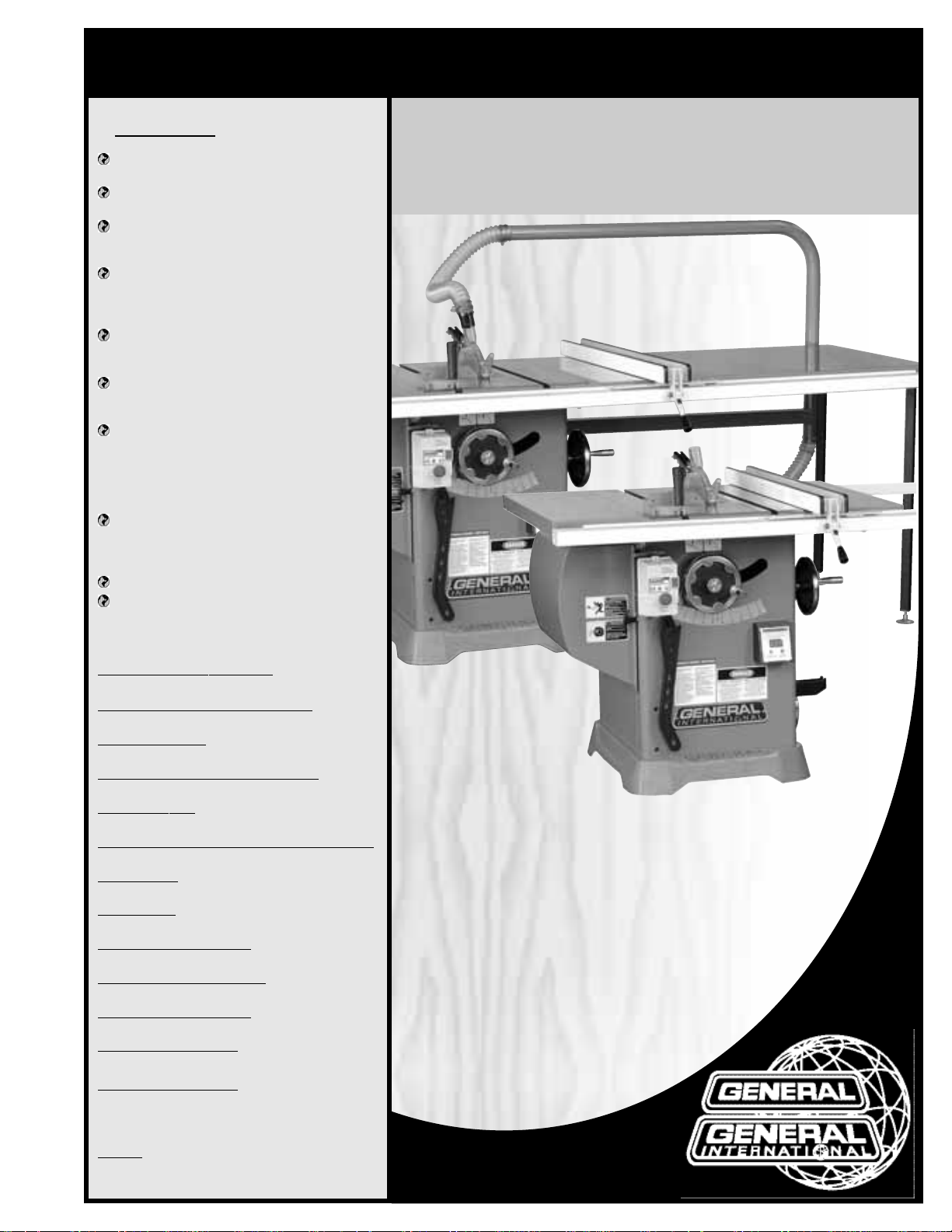
FEATURES
Heavy-Duty enclosed steel cabinet with
cast-iron base for added stability.
Built-in retractable castor system provides
mobility when needed.
Solid wide-stance cast-iron trunnions ensure blade alignment and allow for stable
vibration free cuts.
Large 42”x 29”cast-iron table including two
11”cast-iron extensions – models 50-300/305
only.
(Chrome plated table & extensions on
Deluxe 50-300CE/305CE Chrome Edition.)
4”dust port on cabinet with 2 1/2” branch
inlet to blade guard for easy efficient dust
collection hook up.
See-through blade guard with built-in 2 1/2”
dust outlet for direct dust extraction hook
up.
High precision General “T-Fence”system
with 50” long rails.
(Deluxe 50-300CE/ 305CE
Chrome edition includes same fence,
36”chrome coated steel extension table and
adjustable support legs, steel dust tube and
2 1/2”upper and lower branch dust hoses.)
Quick release combination riving style splitter and blade guard with anti-kickback
pawls and a second European style riving
knife also included.
Unique digital display for blade angle.
Convenient arbor lock for fast one tool
blade changes.
SPECIFIC
ATIONS
BLADE DIAMETER / ARBOR DIAMETER
10”(254 MM) / 5⁄8”
ARBOR
TILT RANGE
0° - 45° (TO LEFT)
MAXIMUM DEPTH OF CUT AT 90° / 45°
3”(77 MM) / 2 3⁄16” (56 MM)
DADO CAPACITY
13/16”(21 MM)
DUST PORT DIAMETER (CABINET/BLADE GUARD)
4”(102 MM) / 2 1⁄2” (64 MM)
ARBOR SPEED
4300 RPM
TABLE HEIGHT
34”(863 MM)
TABLE SIZE (W/EXTENSION)
42”X 29” (1066 X 736 MM)
TABLE SIZE (W/O EXTENSION)
20”X 29” (508 X 736 MM)
BASE DIMENSIONS (L X W)
22 3⁄4”X 26” (580 X 660 MM)
MO
TOR (50-300/300CE)
M1 3 HP, 220V, 1PH, 11.7 A
MOTOR (50-305/305CE)
M1 5 HP, 220V, 1PH, 15.2 A
M2 5 HP, 220V, 3 PH, 13 A
M3 5 HP, 600V, 3 PH, 4.7 A
WEIGHT
(50-300/305): 492 LBS (223 KG)
(50-300CE/305CE): 562 LBS (255 KG)
SETUP & OPERATION MANUAL
10” TILTING ARBOR SAW
REVISION 1 - July 14/09
© Copyright General® International 07/2009
- Left Tilt
MODELS
#50-300/305 M1
#50-300CE/305CE
50-300/305 M1
50-300CE/305CE
Page 2

THANK Y OU
for choosing this General®International model 50-300/305 M1 or
50-300CE/305CE 10" Left Tilting Arbor Saw. This saw has been carefully tested and inspected
before shipment and if properly used and maintained, will provide you with years of reliable
service.To ensure optimum performance and trouble-free operation,and to get the most from
your investment, please take the time to read this manual before assembling, installing and
operating the unit.
The manual’s purpose is to familiarize you with the safe operation,basic function,and features
of this saw as well as the set-up,maintenance and identification of its par ts and components.
This manual is not intended as a substitute for formal woodworking instruction, nor to offer the
user instruction in the craft of woodworking. If you are not sure about the safety of performing
a certain operation or procedure,do not proceed until you can confirm,from knowledgeable
and qualified sources, that it is safe to do so.
Once you’ve read through these instructions, keep this manual handy for future reference.
Disclaimer:
The information and specifications in this
manual pertain to the unit as it was supplied from the
factory at the time of printing. Because we are committed to making constant improvements, General
®
International reserves the right to make changes to components,parts or features of this unit as deemed necessary,
without prior notice and without obligation to install any
such changes on previously delivered units.Reasonable
care is taken at the factory to ensure that the specifications and information in this manual corresponds with
that of the unit with which it was supplied. However, special orders and “after factory”modifications may render
some or all information in this manual inapplicable to
your machine. Further, as several generations of this
model of saw and several versions of this manual may
be in circulation, if you own an earlier or later version of
this unit, this manual may not depict your machine
exactly. If you have any doubts or questions contact
your retailer or our support line with the model and serial number of your unit for clarification.
GENERAL® INTERNATIONAL
8360 Champ-d’Eau, Montreal (Quebec) Canada H1P 1Y3
Telephone (514) 326-1161 • Fax (514) 326-5555 • www.general.ca
Page 3

GENERAL®MFG & GENERAL®INTERNATIONAL WARRANTY
All component parts of General® MFG, General® International and Excalibur by General
International ® products are carefully inspected during all stages of production and each unit
is thoroughly inspected upon completion of assembly.
Limited Lifetime
Warranty
Because of our commitment to quality and customer satisfaction, General® MFG and
General® International agree to repair or replace any part or component w hich upon examination, proves to be defective in either workmanship or material to the original purchaser
for the life of the tool.
However, the Limited Lifetime Warranty does not cover any product used
for professionnal or commercial production purposes nor for industrial or educational applications. Such cases are covered by our Standard 2-year Limited Warranty only. The Limited
Lifetime Warranty is also subject to the “Conditions and Exceptions”as listed below.
Standard 2-Year Limited Warranty
All products not covered by our lifetime warranty including products used in commercial,
industrial and educational applications are warranted for a period of 2 years (24 months) from
the date of purchase. General® MFG and General® Inter national agree to repair or replace
any part or component which upon examination, proves to be defective in either workmanship or material to the original purchaser during this 2-year warranty period, subject to the
“conditions and exceptions”as listed below.
T
o file a Claim
To file a claim under our Standard 2-year Limited Warranty or under our Limited Lifetime
Warranty, all defective parts , components or machiner y must be returned freight or postage
prepaid to General® International, or to a nearby distr ibutor, repair center or other location
designated by General® International. For further details call our service department at 1-888949-1161 or your local distributor for assistance when filing your claim.
Along with the return of the product being claimed for warranty, a copy of the original proof
of purchase and a “letter of claim”must be included (a warranty claim form can also be used
and can be obtained,upon request,from General® International or an authorized distributor)
clearly stating the model and serial number of the unit (if applicable) and including an explanation of the complaint or presumed defect in material or workmanship.
CONDITIONS AND EXCEPTIONS:
This coverage is extended to the original purchaser only. Prior warranty registration is not
required but documented proof of purchase i.e. a copy of original sales invoice or receipt
showing the date and location of the purchase as well as the purchase price paid, must be
provided at the time of claim.
Warranty does not include f ailures,breakage or defects deemed after inspection by General®
MFG or General® International to have been directly or indirectly caused by or resulting from;
improper use, or lack of or improper maintenance, misuse or abuse, negligence, accidents,
damage in handling or transport, or normal wear and tear of any generally considered consumable parts or components .
Repairs made without the written consent of General® Interna tionallwill void all warranty.
Page 4

TABLE OF CONTENTS
SAFETY RULES . . . . . . . . . . . . . . . . . . . . . . .5
ELECTRICAL REQUIREMENTS . . . . . . . . . . . . . .6
Electrical Connections . . . . . . . . . . . . . . . . . . . . . . .6
Grounding instructions . . . . . . . . . . . . . . . . . . . . . . .6
Circuit capacity . . . . . . . . . . . . . . . . . . . . . . . . . . . . .6
Extension cords . . . . . . . . . . . . . . . . . . . . . . . . . . . . .6
IDENTIFICATION OF MAIN PARTS AND COMPO-
NENTS . . . . . . . . . . . . . . . . . . . . . . . . . . . .
7
BASIC FUNCTIONS . . . . . . . . . . . . . . . . . . . .8
PLACEMENT WITHIN THE SHOP / ESTABLISHING
A SAFETY ZONE . . . . . . . . . . . . . . . . . . . . . . .
8
UNPACKING . . . . . . . . . . . . . . . . . . . . . . . .9
List of contents . . . . . . . . . . . . . . . . . . . . . . . . . . . . . .9
Additional requirements for set up . . . . . . . . . . . . .9
CLEAN UP . . . . . . . . . . . . . . . . . . . . . . . . .10
ASSEMBLY INSTRUCTIONS . . . . . . . . . . . . . .10
Install the blade tilt adjustment hand wheel . . . .10
Install the handle onto the retractable castor
system hand wheel . . . . . . . . . . . . . . . . . . . . . . . . .11
Install the miter gauge and T-fence storage
brackets . . . . . . . . . . . . . . . . . . . . . . . . . . . . . . . . . .11
Mount the switch . . . . . . . . . . . . . . . . . . . . . . . . . . .11
Install the table extension wings . . . . . . . . . . . . . .11
Install the motor cover door . . . . . . . . . . . . . . . . . .11
Install the “T-Fence” assembly . . . . . . . . . . .12
Front fence rail . . . . . . . . . . . . . . . . . . . . . . . . . . . . .12
Rear fence rail . . . . . . . . . . . . . . . . . . . . . . . . . . . . .12
Install the table extension, dust tube and hoses -
model 50-300CE & 305CE only . . . . . . . . . . . . . . .13
Table extension . . . . . . . . . . . . . . . . . . . . . . . . . . . .13
Dust tube . . . . . . . . . . . . . . . . . . . . . . . . . . . . . . . . . .14
Dust hoses . . . . . . . . . . . . . . . . . . . . . . . . . . . . . . . . .14
Connecting to a dust collector . . . . . . . . . . .15
Install / remove a saw blade . . . . . . . . . . . . .15
Install a saw blade . . . . . . . . . . . . . . . . . . . . . . . . .15
To remove a saw blade . . . . . . . . . . . . . . . . . . . . .16
Install and adjust riving knife . . . . . . . . . . . .16
Select a riving knife . . . . . . . . . . . . . . . . . . . . . . . . .16
Removal/Installation . . . . . . . . . . . . . . . . . . . . . . . .17
Adjustment/Alignment . . . . . . . . . . . . . . . . . . . . . .17
Setting the splitter/knife 90º to the table . . . . . . .17
Setting the splitter/knife parallel to
and centered on the blade . . . . . . . . . . . . . . . . .18
Level the table insert . . . . . . . . . . . . . . . . . .18
BASIC ADJUSTMENTS AND CONTROLS . . . . . .18
Connecting to a power source . . . . . . . . . . . . . . .18
ON/OFF magnetic power switch . . . . . . . . . . . . . .19
Blade height & tilt adjustment . . . . . . . . . . . .19
Blade height adjustment . . . . . . . . . . . . . . . . . . . .19
Blade tilt (bevel) adjustment . . . . . . . . . . . . . . . . .19
Resetting digital bevel angle readout . . . . . . .20
Operating/engaging the mobile base . . . . . . .20
OPERATING INSTRUCTIONS . . . . . . . . . . . . .21
Types of cuts . . . . . . . . . . . . . . . . . . . . . . .21
Ripping . . . . . . . . . . . . . . . . . . . . . . . . . . . . . . . . . . .21
Bevel ripping . . . . . . . . . . . . . . . . . . . . . . . . . . . . . .22
Ripping small work pieces . . . . . . . . . . . . . . . . . . .22
Cross cutting . . . . . . . . . . . . . . . . . . . . . . . . . . . . . . .22
Bevel cross cutting . . . . . . . . . . . . . . . . . . . . . . . . . .22
Adjusting and using the miter gauge . . . . . . .23
Adjusting the miter gauge . . . . . . . . . . . . . . . . . . .23
Adding an auxiliary fence to the miter gauge . .23
Marking wood . . . . . . . . . . . . . . . . . . . . . . . . . . . . .23
Miter cuts . . . . . . . . . . . . . . . . . . . . . . . . . . . . . . . . . .24
Compound miter cuts . . . . . . . . . . . . . . . . . . . . . . .24
Using a dado head blade . . . . . . . . . . . . . . .24
MAINTENANCE & ADJUSTMENTS . . . . . . . . . .24
Periodic maintenance . . . . . . . . . . . . . . . . . . . . . .24
Lubrication . . . . . . . . . . . . . . . . . . . . . . . . . . . . . . . .25
Adjusting the 90 º bevel stop . . . . . . . . . . . . . . . . .25
Adjusting the bevel angle pointer . . . . . . . . . . . .25
Adjusting the 90 º bevel stop . . . . . . . . . . . . . . . . .25
Recommended optional accessories . . . . .26
Parts list and diagrams . . . . . . . . . . .27 - 36
Wiring diagrams . . . . . . . . . . . . . . . . .37 - 39
Page 5

RULES FOR SAFE OPERATION
To help ensure safe operation, please take a moment to learn the machine’s applications and limitations, as well as potential hazards. General® International disclaims any real or implied warranty and holds itself harmless for any injury that
may result from improper use of its equipment.
1. Do not operate the saw when tired, dis tracted, or
under the effects of drugs, alcohol or any medication that impairs reflexes or alertness.
2. The working area should be well lit, clean and free
of debris.
3. Keep children and visitors at a safe distance when
the saw is in operation; do not permit them to
operate the saw.
4. Childproof and tamper proof your shop and all
machinery with locks, master electrical switches
and switch keys, to prevent unauthorized or unsupervised use.
5. Stay alert! Give your work your undivided attention.Even a momentary distraction can lead to serious injury.
6. Fine particula te dust is a carcinogen that can be
hazardous to health. Work in a well-ventilated area
and whenever possible use a dust collector and
wear eye,ear and respiratory protection devices.
7. Do not wear loose clothing,gloves,bracelets, necklaces or other jewelry while the saw is in operation.
Wear protective hair covering to contain long hair
and wear non-slip footwear.
8. Be sure that adjusting wrenches, tools, drinks and
other clutter are removed from the machine and/or
the feed table surface before operating.
9. Keep hands well away from the blade and all moving parts. Use a br ush, not hands, to clear away
chips and dust.
10. Be sure that the blade is securely installed and in
proper cutting direction before operation.
11. Be sure the blade has gained full operating speed
before beginning to cut.
12. Always use a clean, properly sharpened blade.
Dirty or dull blades are unsafe and can lead to
accidents.
13. If using a power feeder,stop the feeder before stopping the table saw.
14. Do not push or force stock into the blade. The saw
will perform better and more safely when working
at the rate for which it was designed.
15. Use suitable suppor t when cutting stock that does
not have a flat surface. Always hold stock firmly
against the fence when ripping,or against the miter
gauge when cross-cutting.
16. To minimize risk of injury in the event of workpiece
kickback,never stand directly in-line with the blade
or in the potential kickback path of the work piece.
17. Avoid working from awkward or off balance positions. Do not overreach while cutting; keep both
feet on floor. Never lean over or reach over the
blade and never pull the work piece o ver the blade
from behind.Use out feed support or have an assistant help when ripping long material.
18. Keep blade guards in place and in working order.
If a guard must be removed for maintenance or
cleaning, be sure it is properly reattached before
using the tool again.
19. Never leave the machine running with the power
on when not in operation.
20. Use of parts and accessor ies NOT recommended
by
GENERAL® INTERNATIONAL
may result in equip-
ment malfunction or risk of injury.
21. Never stand on machinery. Serious injury could
result if the tool is tipped over or if the blade is unintentionally contacted.
22. Always disconnect tool from power bef ore servicing
or changing accessories such as blades, or before
performing any maintenance, cleaning or adjustments, or if the machine will be left unattended.
23. Make sure that switch is in "OFF" position before
plugging in the power cord.
24. Make sure the tool is properly grounded. If equipped with a 3-prong plug it should be used with a
three-pole receptacle. Never remove the third
prong.
25. Do not use this saw for other than its intended use. If
used for other purposes,
GENERAL® INTERNATIONAL
disclaims any real implied warranty and holds itself
harmless for any injury, which may result from that
use.
5
Page 6
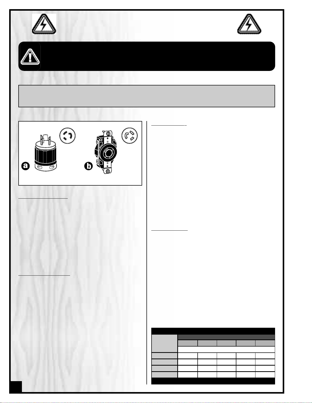
ELECTRICAL CONNECTIONS
Both a manual circuit breaker (or similar de vice) as well
as an electrical plug are recommended and should
be installed by a qualified electrician. Use locally a pproved wire that includes a separate grounding wire
and a 3 prong grounding type plug A with a matching
receptacle B .
GROUNDING INSTRUCTIONS
In the event of an electrical malfunction or short circuit,
grounding reduces the risk of electric shock to the operator.The motor of this machine is wired for 220V single
phase operation. As with many stationary industrial
type machines, because each installation situation is
unique, this table saw is supplied without a power cord
or plug. The installation of an appropriate power cord
and plug must be performed by a qualified electrician.
The machine must be connected to an electrical
source using a power cord that has a grounding wire,
which must also be properly connected to the grounding prong on the plug. The outlet must be properly
installed and grounded and all electrical connections
must be made in accordance with all local codes and
regulations.
BEFORE CONNECTING THE MACHINE TO THE POWER SOURCE,VERIFY THAT THE VOLTAGE OF YOUR POWER SUPPLY CORRESPONDS
WITH THE VOLTAGE SPECIFIED ON THE MOTOR I.D. NAMEPLATE. A POWER SOURCE WITH GREATER VOLTAGE THAN NEEDED CAN
RESULT IN SERIOUS INJURY TO THE USER AS WELL AS DAMAGE TO THE MACHINE. IF IN DOUBT,CONTACT A QUALIFIED ELECTRICIAN
BEFORE CONNECTING TO THE POWER SOURCE.
THIS TOOL IS FOR INDOOR USE ONLY. DO NOT EXPOSE TO RAIN OR USE IN WET OR DAMP LOCATIONS.
CIRCUIT CAPACITY
Make sure that the wires in your circuit are capable of
handling the amperage draw from your machine, as
well as any other machines that could be operating on
the same circuit. If you are unsure, consult a qualified
electrician. If the circuit breaker trips or the fuse blows
regularly, your machine may be operating on a circuit
that is close to its amperage draw capacity.However,if
an unusual amperage draw does not exist and a
power failure still occurs,contact a qualified technician
or our service depar tment.
EXTENSION CORDS
The use of an extension cord is not generally recommended for 220V equipment. If you find it necessary,
use only 3-wire extension cords that have 3-prong
grounding plug and a matching 3-pole receptacle that
accepts the tool’s plug. Repair or replace a damaged
extension cord or plug immediately.
If you find it necessary to use an extension cord with
your machine make sure the cord rating is suitable for
the amperage listed on the motor I.D. plate. An undersized cord will cause a drop in line voltage resulting in
loss of power and overheating. The accompanying
chart shows the correct size extension cord to be used
based on cord length and motor I.D.plate amp rating.
If in doubt, use the next heavier gauge. The smaller the
number, the heavier the gauge.
6
NOTE: VOLTAGE REQUIREMENTS AND AMPERAGE DRAW FOR 5HP M2 & M3 3-PHASE MOTORS MAY NOT BE FULLY DESCRIBED IN THIS MANUAL. FOR COMPLETE ELECTRICAL REQUIREMENTS REFER TO THE MOTOR I.D. NAME PLATE ON
THE MACHINE. IF IN DOUBT CONSULT A LICENSED QUALIFIED ELECTRICIAN BEFORE PROCEEDING.
ELECTRICAL REQUIREMENTS
TABLE - MINIMUM GAUGE FOR CORD
AMPERE
RATING
TOTAL LENGTH OF CORD IN FEET
220 VOLTS 50 FEET 100 FEET 200 FEET 300 FEET
AWG
< 5
------->
18 16 16 14
6 TO 10
------->
18 16 14 12
10 TO 12
------->
16 16 14 12
12 TO 16
------->
14 12 * NR * NR
* NR = Not Recommended
Page 7
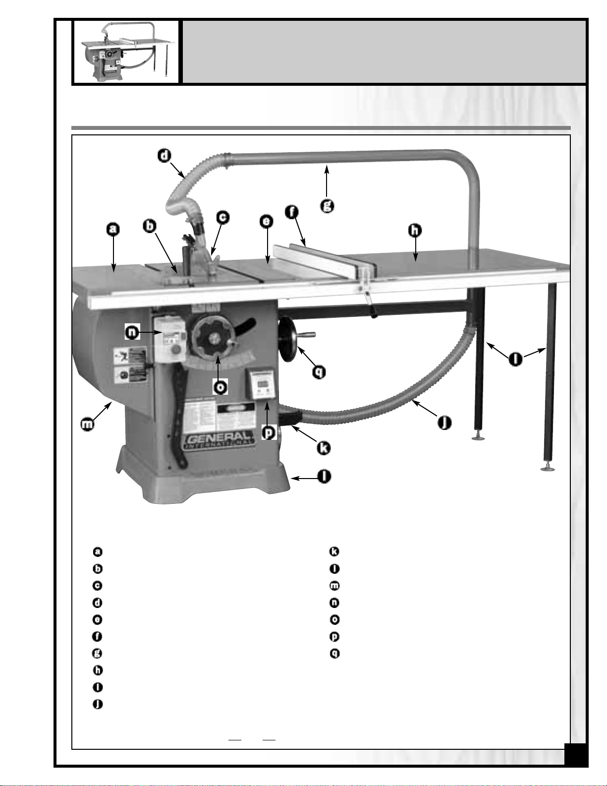
10” TILTING ARBOR SAW – LEFT TILT
50-300/305 M1 – 50-300CE/305CE (Model 50-300CE shown)
IDENTIFICATION OF MAIN PARTS AND COMPONENTS
LEFT TABLE EXTENSION WING
MITER GAUGE
SPLITTER/BLADE GUARD ASSEMBLY
DUST HOSE TO GUARD*
RIGHT TABLE EXTENSION WING
RIP FENCE
DUST TUBE*
CHROME EXTENSION TABLE*
ADJUSTABLE SUPPORT LEGS*
DUST HOSE TO TUBE*
T-FENCE STORAGE BRACKETS
MOBILE BASE
MOTOR COVER DOOR
MAGNETIC SAFETY SWITCH
BLADE HEIGHT ADJUSTMENT HAND WHEEL
BLADE ANGLE DIGITAL DISPLAY
BLADE TILT ADJUSTMENT HAND WHEEL
7
*Included with Model 50-300CE/305CE only.
Page 8
BASIC FUNCTIONS
The General International model 50-300 cabinet saw is available with various motor size and electrical voltage requirement options. Standard 3 HP motor option carries model number 50-300 M1 and 5 HP motor options are available under
model number 50-305 M1, M2 or M3, based on motor operating voltage (see manual coverpage for complete list).
An optional deluxe Chrome Edition is also available, including chrome-coated main table and extensions wings, 36”
chrome-coated steel extension table with adjustable support legs,and an onboard overhead dust extraction system (dust
collector sold separately) under model number 50-300CE M1 and 50-305CE M1, M2 or M3.
This cabinet saw has been designed for cutting solid wood as well as manufactured wood materials such as plywood,
wood paneling,particleboard, mdf and other wood based by-products.This saw is not designed for cutting metals nor for
cutting any materials other than wood or wood based stock.
This saw is designed for use with maximum 10" (254 mm) diameter blades having a center hole diameter of 5/8".
The blade can be raised to cut a maximum stock thickness of 3" with the blade set 90 degrees to the table.The blade can
be tilted up to 45 degrees to the left for bevel cuts to a maximum stock thickness of 2 1/8".Using any standard aftermarket 8" diameter stacked dado blade set (not included),the maximum dado cutting capacity of this saw is 13/16". Note:
for safer dado cutting,an optional dado table insert (#50-302) can be purchased through your General International distributor.
To encourage safety through the proper use of either the supplied riving style splitter/blade guard assembly or the
European style riving knife the 50-300/300CE/305/305CE have been designed with a quick install/quick release feature
allowing the user to install or remove either of these safety components in seconds.
For added convenience,a retractable built-in caster system is included to allow the user to engage the wheels in order to
move the saw as needed within the shop.Once moved to the desired location the saw can then be set firmly back onto
the floor.
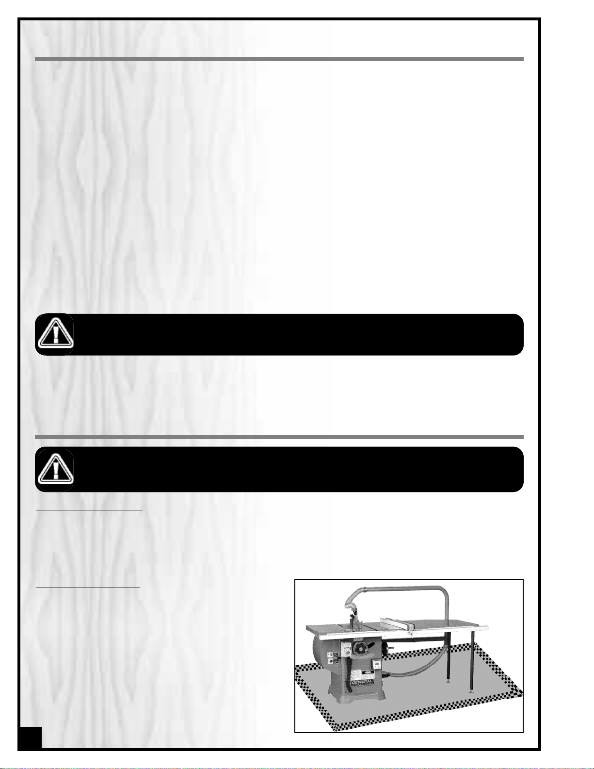
PLACEMENT WITHIN THE SHOP /
ESTABLISHING A SAFETY ZONE
PL
ACEMENT WITHIN THE SHOP
This machine should be installed and operated only on a solid, flat and stable floor that is able to support the
weight of the saw and the operator.
Plan for placement within your shop that will allow the operator to work unencumbered and unobstructed by foot
traffic (either passing shop visitors or other shop workers) or other tools or machinery.
ESTABLISHING A SAFETY ZONE
For shops with frequent visitors or multiple operators, it is
advisable to establish a safety zone around shop machinery. A clearly defined “no-go” zone on the floor around
each machine can help avoid accidents that could cause
injury to either the operator or the shop visitor. It is advisable to take a few moments to either paint (using non-slip
paint) or using tape,define on the floor the limits or perimeter of each machines safety zone.Take steps to ensure that
all operators and shop visitors are aware that these areas
are off limits whenever a machine is running for everyone
but the individual operating the unit.
THIS MODEL 50-300 10" TILTING ARBOR SAW IS HEAVY. DO NOT OVER-EXERT.A HOIST OR FORKLIFT WITH STRAPS SHOULD BE USED
TO LIFT THIS MACHINE.
TO LIMIT THE RISK OF SERIOUS INJURY OR DAMAGE TO THE MACHINE,ANY EQUIPMENT USED TO LIFT THIS MACHINE SHOULD HAVE
A RATED CAPACITY IN EXCESS OF 492 LBS (223 KG) FOR MODELS 50-300/305 AND OF 562 LBS (255 KG) FOR MODELS 50300CE/305CE.
8
NEVER MOVE THE SAW WHILE IT IS RUNNING AS THIS CAN LEAD TO SERIOUS INJURIES. ALWAYS MAKE SURE THAT THE WHEELS OF
THE MOBILE BASE HAVE BEEN DISENGAGED AND THAT THE SAW HAS BEEN COMPLETELY IMMOBILIZED BEFORE TURNING ON THE
SAW AND STARTING TO CUT.
Page 9
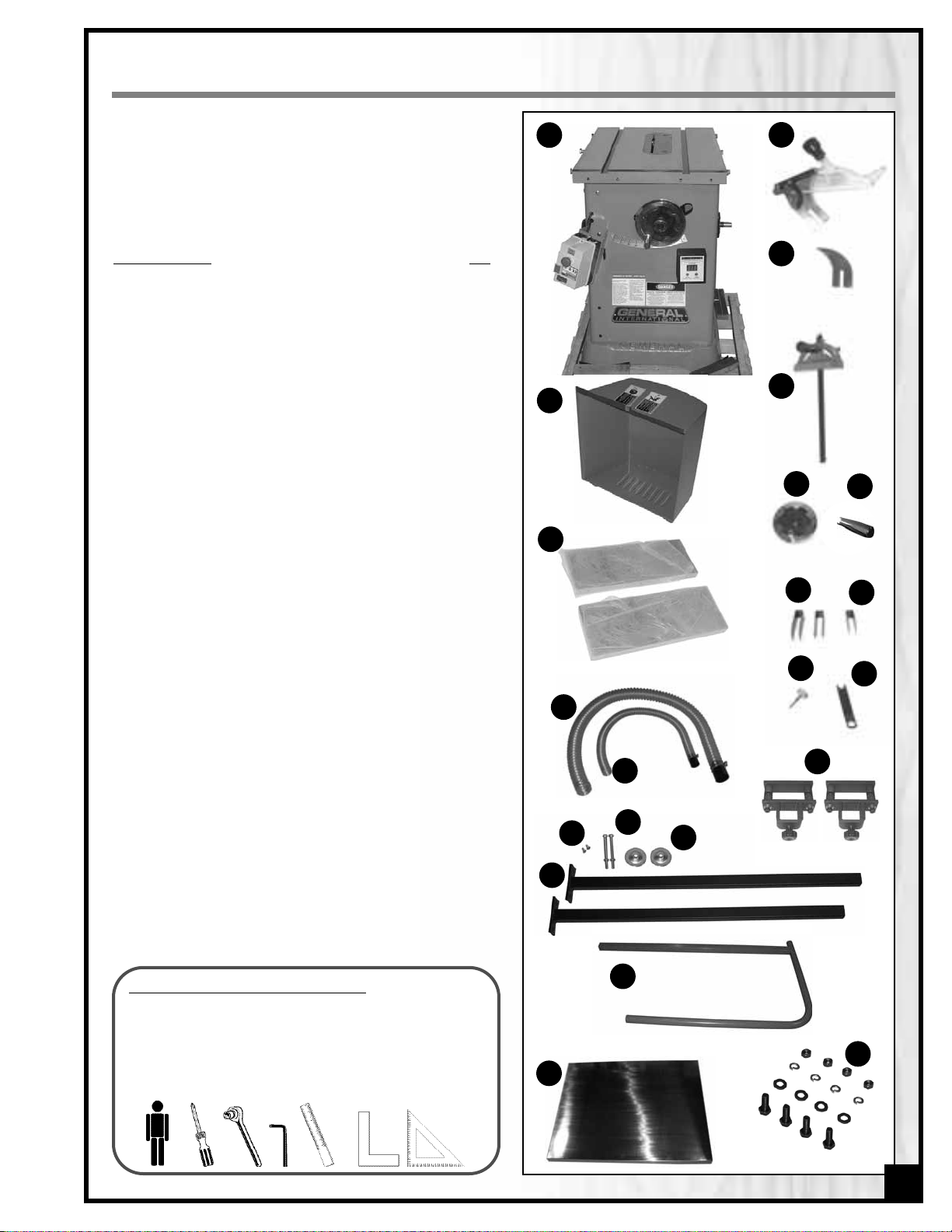
UNPACKING
Carefully unpack and remove the saw and its components from the box and check for damaged or missing
items as per the list of contents below.
NOTE: Please report any damaged or missing items to your
General® International distributor immediately.
LIST OF CONTENTS QTY
A - SAW .................................................................................1
B -
MOTOR COVER DOOR ..................................................1
C - TABLE EXTENSION ...........................................................2
D - SPLITTER / BLADE GUARD ...............................................1
E - RIVING KNIFE ..................................................................1
F - MITER GAUGE.................................................................1
G - BLADE TILT ADJUSTMENT HAND WHEEL..........................1
H - RETRACTABLE CASTOR SYSTEM HAND WHEEL HANDLE... 1
I - T-FENCE STORAGE BRACKET...........................................2
J - MITER GAUGE STORAGE BRACKET................................1
K - BLADE TILT HAND WHEEL LOCK KNOB..........................1
L - ARBOR KEY .....................................................................1
M- DUST HOSE TO TUBE W/HOSE CLAMP &
HOSE ADAPTER
(50-300CE/305CE ONLY)..........................1
N - DUST HOSE TO GUARD W/HOSE CLAMP &
HOSE ADAPTER
(50-300CE/305CE ONLY)..........................1
O - SCREW
(50-300CE/305CE ONLY).......................................2
P - BOLT & NUT
(50-300CE/305CE ONLY)................................2
Q- LEG FLANGE
(50-300CE/305CE ONLY)..............................2
R - LEG
(50-300CE/305CE ONLY) ............................................2
S - OVERARM SUPPORT BRACKET
(50-300CE/305CE ONLY)....................................................2
T - DUST TUBE
(50-300CE/305CE ONLY)..................................1
U - CHROME EXTENSION TABLE
(50-300CE/305CE ONLY)....................................................1
V - EXTENSION TABLE LEG MOUNTING HARDWARE
(50-300CE/305CE ONLY)....................................................1
NOTE: F-42 rip fence and T-50 guide rails are packaged separately.
A
B
9
ADDITIONAL REQUIREMENTS FOR SET UP
• Extra person for help with lifting
• Phillips Screwdriver
• 10 mm and 7/16”socket wrenches
• 3 mm and 4 mm Allen keys
• Straightedge
• Machinist square or triangle square
OR
C
D
E
F
G
H
I
J
K
I
M
N
R
Q
P
O
T
U
V
S
Page 10
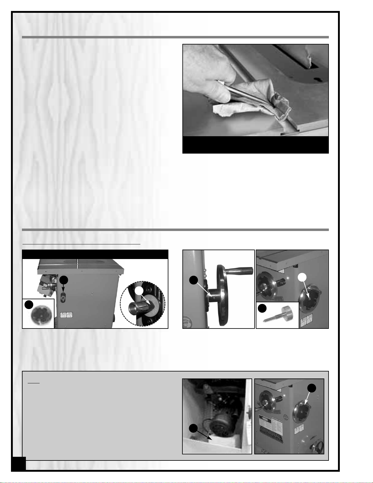
CLEAN UP
The protective coating on the saw table prev ents rust from
forming during shipping and storage. Remove it by rubbing with a rag dipped in kerosene, mineral spirits or
paint thinner. (Dispose of potentially flammable solventsoaked rags according to manufacturer’s safety recommendations.)
A putty knife, held flat to avoid scratching the surface,
may also be used to scrape off the coating followed by
clean-up with solvent. Avoid rubbing the saw’s painted
surfaces, as many solvent-based products will remove
paint.
To prevent rust, apply a light coating of paste wax or use
regular applications of any after-market surface protectant or rust inhibitor.
Tip: With a screw driver,push a solvent-saturated rag into
the T-slots to remove the grease.
INST
ALL THE BLADE TILT ADJUSTMENT HAND WHEEL
ASSEMBLY INSTRUCTIONS
1. Install the blade tilt adjustment hand wheel A onto
the upper shaft B on the right side of the saw.
Note: First remove the adhesive tape Cthat holds the key
into the hand wheel shaft.
2. Tighten the set screw D to secure the hand w heel
on the shaft using a Allen key, then install the lock
knob E into the hand wheel shaft F to secure the
hand wheel in place.
RIGHT SIDE VIEW
A
C
Note
To limit the potential for damage in transport, this ta ble
saw is shipped from the factory with the motor sitting on
a styrofoam block G for support.
Turn the hand wheel H, located on the right side of the
saw, counter-clockwise to raise the motor enough to
remove the styrofoam block
H
G
10
B
E
D
F
Page 11
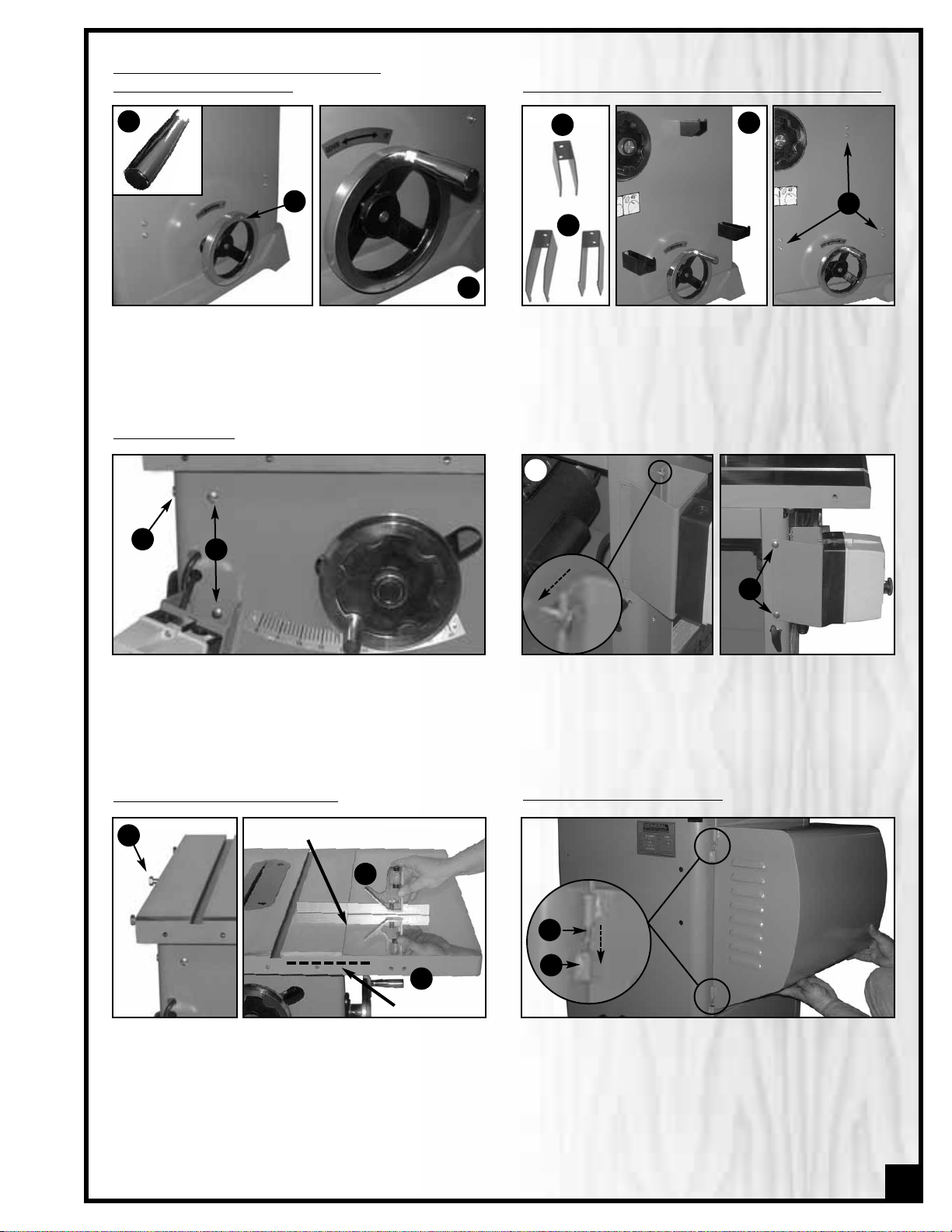
MOUNT THE SWITCH
1. Loosen the two bolts N on front of the saw and
remove the two bolts O on the left side of the saw.
2. Slide the switch mounting bracket onto the front
bolts P and tighten from inside the cabinet with a
10 mm socket wrench, then re-install and tighten
the side bolts Q.
N
O
P
Q
flush here
level here
Attach the table extension wings to the main table
using the 7/16” mm hex head bolts (3 per wing)
already mounted on both sides of the main table R.
Align the table extensions with the table and loosely
attach the bolts.Place a straightedge on the table and
extension as shown in S to align the extension table
and then tighten down the bolts.
Note: Be sure that the table extension wings are flush with
front edge of table T.
R
T
S
Install the motor cover door on the left side of the saw
by inserting the rods V into the hole of the motor cover
door support W.
Note: If you have purchased either Deluxe 50-300CE or
50-305CE Chrome edition, please skip ahead to the “Install the table extension, dust tube and dust hoses” installation instructions on page 13 before installing the motor
door cover.
INSTALL THE MOTOR DOOR COVER
INSTALL THE TABLE EXTENSION WINGS
W
V
11
INST
ALL THE HANDLE ONTO THE RETRACTABLE
CASTOR SYSTEM HAND WHEEL
Thread the handle G onto the retractable castor system hand wheel H on the right side of the saw as shown
in I.
INSTALL THE MITER GAUGE AND T-FENCE STORAGE BRACKETS
Install the miter gauge storage bracket J (the smaller
one) and the T-fence storage brackets K on the right
side of the saw as shown in L, using the screws M
already mounted on the right side of the cabinet.
G
H
I
J
K
L
M
Page 12
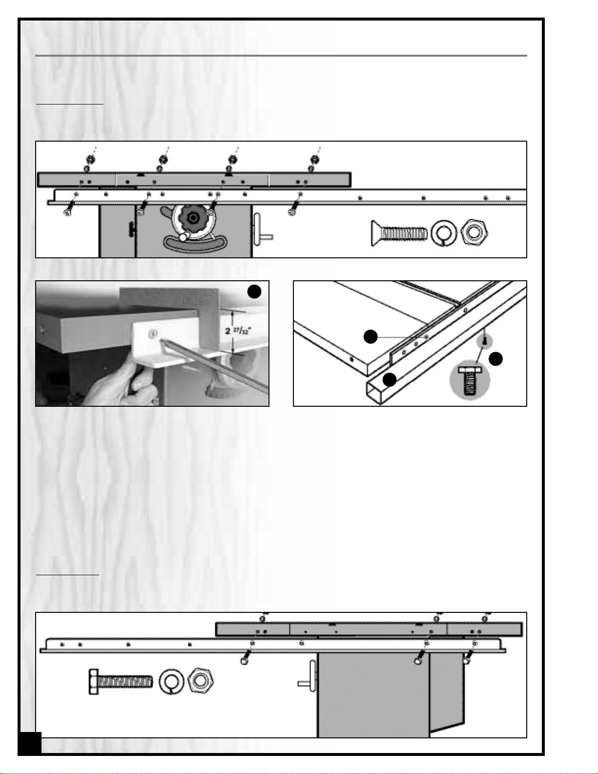
2. Place the supplied L-jig, as shown at far right A, on
top of the table. Adjust the rail height until the bottom of the jig is flush with the rail shelf. Hold the nuts
firm with a 7/16" wrench and tighten the two screws
on left and right ends of the rail. Tighten the center
screws only after double-checking rail height using
the L-jig all along the rail and at both ends.
FRONT FENCE RAIL
1. Install the T-50 front guide rail on the front of the saw aligning the holes in the rail with those on the the saw as
shown below.
INSTALL THE T-FENCE ASSEMBLY
Please note that there are detailed installation and operating instructions in the F-42 manual supplied in the box with the
F42 rip fence.
3. Assemble the guide tube B to the front fence rail
by fastening the 7 hex head bolts (3/8”x 3/4”) C to
the underside of the rail.
Note: When the tube is attached, there will be a ga p of
about 1” between it and the rail D in which part of the
fence will ride.
Note: If you have purchased either Deluxe 50-300CE or
50-305CE Chrome edition, please skip ahead to the
“Install the table extension, dust tube and hoses” installation instructions on page 13 before assembling the guide
tube to the front fence rail.
REAR FENCE RAIL
1. Install the T-50 rear guide rail on the rear of the saw aligning the holes in the rail with those on the saw as shown
below.
A
12
D
C
B
Page 13

INSTALL THE TABLE EXTENSION, DUST TUBE AND HOSES
- MODEL 50-300CE & 305CE ONLY
Note: Deluxe 50-300CE/305CE Chrome edition includes 36” chrome coated steel extension table and adjustable support
legs, steel dust tube and 2 1/2” upper and lower branch dust hoses.) The following instructions are specifically related to
the installation of these models options.
If you have purchased either model 50-300 or 50-305 then the following instructions do not apply – please skip ahead to
the “Connecting to a dust collector” installation instructions on page 15.
TABLE EXTENSION
Tip Have an assistant holding the extension table while
tightening the bolts to secure the table extension to the
rails. The table being held in the vertical position as shown
above, star t by attaching the right end of the table to the
rails.
Note: Position the extension table with the cross braces
A
towards the outside.
1. Loosely attach the table extension to the rear rail
with 3 round button head bolts and hex nuts B as
shown.
B
2. Loosely attach the table extension to the front rail
with 3 flat head countersunk screws and hex nuts C
as shown.
C
3. Place a straightedge on the saw table and table
extension as shown to align the extension table
and then tighten down the bolts.
Note: Be sure that the extension table is flush with the saw
table.
4. Thread a bolt D in the bottom of both legs as shown. 5. Install one leg flange onto each leg as shown in E
by threading a screw F through the hole in the
bolt’s head G.
G
13
A
level here
flush here
D
F
E
Page 14

DUST TUBE
2. Insert the dust tube horizontal post into the support
brackets as shown and secure in position by tightening the lock knobs B.
1. Install the dust tube support brackets on the rear of
the saw cabinet as shown, using the backer plate
A of the suppor t brackets assemblies, from inside
the cabinet, to secure the support brackets to the
saw.
A
B
DUST HOSES
2. Attach the (shorter) dust hose to the dust tube
upper end and blade guard dust outlet as shown
above.
Note: If needed, slighlty loosen the screw Eto fit the hose
clamp on the dust tube, then retighten to firmly secure in
place.
1. Remove the dust outlet cap C then attach the
(longer) dust hose to the dust tube and dust outlet
as shown above.
Note: If needed, slighlty loosen the screw Dto fit the hose
clamp on the dust tube, then retighten to firlmy secure in
place.
E
C
D
14
6. Attach the two legs to the extension table with 4 hex
head bolts, lock washers, flat washers and hex nuts
G as shown.
G
Page 15

15
CONNECTING TO A DUST COLLECTOR
• There is a 4" dust outlet A located on the rear of the
saw cabinet allowing for the connection to a dust collection system (not included).
• Be sure to use appropriate size hose and fittings (not
included) and check that all connections are sealed
tightly to minimize airborne dust.
Note: If you have not purchased either model 50-300CE or 50305CE, make sure that the 2 1/2” branch on the dust outlet
B
is sealed with the supplied cap C.
• If you do not already own a dust collection system
consider contacting your General® International distributor for information on our complete line of dust collection systems and accessories or visit our website at
www.general.ca
ALWAYS TURN ON THE DUST COLLECTOR BEFORE STARTING THE SAW AND ALWAYS STOP THE SAW BEFORE TURNING OFF THE
DUST COLLECTOR.
B
A
BE SURE THE SAW IS UNPLUGGED AND COMPLETELY DISCONNECTED FROM THE POWER SOURCE WHENEVER INSTALLING OR
REMOVING A SAW BLADE!
NOTE: This saw is intended for use with 10" (254 mm) diameter or less saw blades having a center hole diameter of 5/8". There are many types of blades available to perform specific cutting jobs, such as crosscuts
or ripping only, or for use with plywood, panelling and other products. A good quality specialty blade can
produce a finer finish, be more efficient and place less strain on the saw. Use only saw blades designed for
operating speeds of 4300 RPM or higher.Saw blades should be kept clean and sharp. Never store saw blades
by stacking them directly in contact with each other. Place a layer of cardboard or similar material between
the blades to keep them from coming into contact with each other.
INSTALL A SAW BLADE
1. Lift the table insert up A and loosen the lock lever B,
then pull the splitter or riving knife up out of its
mounting bracket C.
INSTALL / REMOVE A SAW BLADE
2. Loosen the nut D with the supplied arbor wrench E
and remove the arbor nut & flange F.
A
D
E
F
B C
C
Page 16

5. To remove a saw blade: perform the same procedure turning the arbor nut in the opposite direction.
BEFORE TURNING ON THE SAW, MAKE SURE THE ARBOR LOCK IS DISENGAGED (POPS UP) BY TURNING THE BLADE A FRACTION TO UNLOCK. TURN THE BLADE BY HAND ONE FULL ROTATION TO MAKE SURE THE ARBOR/BLADE TURNS FREELY.
NO
TE
When tightening the arbor nut, take care not to over tighten as this will make it very difficult to remove later.
Because the rotation of the blade runs counter to the direction of the threads on the nut, the blade is essentially tightening itself to the nut whenever the saw is running. Though there are no hard and fast rules for how
much torque is required, the arbor nut should be always tightened hand-tight and just slightly beyond “snug”.
16
3. Install a saw blade on the arbor so that the openings
between the teeth face the front of the saw (the blade spins in the counter-clockwise direction).
FRONT
BLADE DIRECTION
4. Replace the flange and arbor nut. Press down on
the red arbor lock button G so the blade and arbor
won’t turn as you tighten the arbor nut clockwise (toward the rear of the saw) with the supplied arbor
wrench.
G
SELECT A RIVING KNIFE
Two riving knives are provided:
- A European style riving knife without blade guard
A;
- A combination riving style splitter and blade guard
with anti-kickback pawls and built-in 2 1/2” dust outlet B.
The riving knife must always be used with a blade guard.
If you already own an independently attached bladeguard such as our Excalibur 50-EXBC10,use the riving knife
A. If you do not already own a blade guard, use the splitter/blade guard assembly B
.
THE BLADE MUST NEVER REMAIN EXPOSED WHEN USING THE SAW. TO PREVENT THE RISK OF SERIOUS INJURIES, ALWAYS
COVER THE BLADE WITH A BLADE GUARD.
INSTALL AND ADJUST RIVING KNIFE
A
B
Page 17

REMOVAL / INSTALLATION
1. Set the blade to 90º and raise it to its highest position.
(Refer to “Blade height and tilt adjustment”instructions
on page 19 if needed).
2. Remove the table insert.
3. If already installed, remove the splitter or riving knife
by pulling the lock lever toward you A then pulling the
splitter or riving knife up out of its mounting bracket B.
4. T
o install: Fit the bottom end of the splitter or riving
knife into the slot in the mounting bracket and push
downward until it bottoms out, then tighten the lock
lever to lock it in place.
5. Re-install the table insert.
ALWAYS TURN OFF AND UNPLUG THE SAW BEFORE REMOVING / INSTALLING A RIVING KNIFE.
A B
SETTING THE SPLITTER/KNIFE 90º TO THE TABLE
1. With the blade set to 90º to the table, using a square,
verify the perpendicular alignment of the splitter/knife
to the table, A.
2. If needed, loosen or tighten (with a 3 mm allen key)
the two upper B and/or lower C set screws on the splitter/knife mounting bracket,until the splitter/knife is 90º
to the table.
90º
17
ADJUSTMENT / ALIGNMENT
A
ALWAYS TURN OFF AND UNPLUG THE SAW BEFORE PERFORMING ANY ADJUSTMENTS.
The locking screws must first be loosened (with a 4 mm allen key) – 1/4 turn or more, depending upon how much
adjustment is required, in order to be able to adjus t the set screws.
Tip: Tighten each locking screw immediately after adjusting its corresponding set screw to avoid undoing the previous
adjustment.
The splitter/knife mounting bracket consists of: a rocker arm
A, a spacer B, and a hold-down block C. This assembly is
held together by two locking screws D. Both 90º to the table
and parallel/centered to the blade alignments can be
achieved by adjusting the four set screws E.
The riving knife mounting block is alr
eady factory set, and
should not require adjustment out of the box. However with
use over time,re-alignment may be required periodically.
Page 18

LEVEL THE TABLE INSERT
Place the insert into the table and use a straightedge to
determine whether the insert is level with the table top.Turn
each of the 6 adjusting screws A with the a 3 mm Allen key
until done.
Suggestion: Start by adjusting one rear screw and its diagonal
opposite in front, then tweak the remaining screws.
Note: If the saw blade has already been installed, use the
raising hand wheel to lower the blade below the table surface
before leveling the insert.
SETTING THE SPLITTER/KNIFE PARALLEL TO AND CENTERED ON THE BLADE
TABLE REMOVED FOR CLARITY ONLY
A
D
1. Place a straightedge against the splitter/knife A.
2. If needed,loosen or tighten one or both set screws
on both left B and r ight C side of the splitter/knife
mounting bracket until the splitter/knife is parallel
to the blade D.
3. Use a feeler gauge to measure the clearance
between the straightedge and the blade. The
width of the gap must be more or less the same
on each side of the splitter/knife. If needed, readjust the set screws on both right and left side of
the splitter/knife mounting bracket to increase or
decrease the clearance between the straight
edge and the blade.
A
BASIC ADJUSTMENTS & CONTROLS
CONNECTING TO A POWER SOURCE
Once the assembly steps have been completed,plug the
power cord into an appropriate outlet. Refer back to the
section entitled “ELECTRICAL REQUIREMENTS” and make
sure all requirements and grounding instructions are followed. When cutting operations have been completed
unplug the saw from the power source.
TO AVOID UNEXPECTED OR UNINTENTIONAL START-UP,
MAKE SURE THAT THE POWER SWITCH ON THE SAW IS
IN THE OFF POSITION BEFORE CONNECTING TO A
POWER SOURCE.
TO AVOID RISK OF SHOCK OR FIRE DO NOT OPERATE
THE UNIT WITH A DAMAGED POWER CORD OR PLUG.
REPLACE DAMAGED CORD OR PLUG IMMEDIATELY.
SWITCH OFF
18
Page 19

19
This saw is equiped with a MAGNETIC SAFETY SWITCH
located on the control box, designed to protect the
unit and the user from power surges, power outages
and unwanted or unintentional start-up.
The switch assembly is equipped with a GREEN “START”
button A and a RED spr ing loaded “STOP”button B.
Once the RED “STOP” button has been pressed, the
machine can only be started by turning the BLACK
inner part of the button to the right C to release the
stop button.
ON/OFF MAGNETIC POWER SWITCH
A
B
C
BLADE HEIGHT ADJUSTMENT
The blade height adjustment hand wheel is located on
the front of the saw A and there is a lock knob B on the
hand wheel that allows you to lock the wheel and secure
the blade at the desired height.
To raise or lower the blade:
1. Loosen the blade height lock knob B by turning
counter clockwise.
2. T
o raise the blade: turn the hand wheel A clockwise.
T
o lower the blade:
turn the hand wheel A counter
clockwise.
3. With the blade set to the desired height, tighten the lock knob B by turning clockwise to lock the blade.
TO LIMIT YOUR EXPOSURE TO THE BLADE AND ALSO TO MAXIMISE THE EFFECTIVENESS OF THE ANTI-KICKBACK
P AWLS (WHEN USING THE RIVING STYLE SPLITTER & BLADE GUARD), NEVER TAKE MORE BLADE HEIGHT THAN
IS REQUIRED TO COMPLETE THE CUT.WHEN SETTING THE BLADE HEIGHT FOR THROUGH-CUTS (CUTS ALL THE
WAY THROUGH THE THICKNESS OF A BOARD) SET THE HEIGHT OF THE BLADE TO ROUGHLY 1/4" HIGHER
THAN THE THICKNESS OF THE BOARD.
BLADE TILT (BEVEL) ADJUSTMENT
The blade tilt (bevel) adjustment hand wheel is located
on the side of the saw C and there is a lock knob D on the
hand wheel that allows you to lock the wheel and secure
the blade at the desired angle.
To change the angle of the blade:
1. Loosen the bevel lock knob D by turning it counterclockwise.
2. Turn the hand wheel C left or right as required to set
the blade to the desired angle. The blade can be tilted to the left anywhere from 0° (90° to the table) to
45°.
3. With the blade tilted to the desired angle, tighten the lock knob by turning it clockwise to lock the tilting mechanism and secure the blade.
BLADE HEIGHT & TILT ADJUSTMENT
A
B
C
D
Page 20

Upon plugging in the machine and pressing on the ON/OFF button A,the digital readout will show “0.0”.
RESETTING DIGITAL BEVEL ANGLE READOUT
1. Set the blade to 90° ver tical to the table and use a
machinist square or triangle square to validate the
angle.
2. If the digital readout does not show “0.0”, press the
“reset” button B on the digital readout so it shows
“ 0.0”.
Note:
•
The bevel angle calibration must be reset each time you plug in the machine.
•
To avoid the risk of electrocution and/or damage to the circuitry do not disassemble the electrical components.
•
If the digital display should fail – replace with a new unit, do not attempt to repair.
A B
Note
The bolt Bin the bottom rear of the saw is for adjusting
the mobile base chain tension. The chain tension has
been factory set and needs no further adjustment.
OPERATING/ENGAGING THE MOBILE BASE
The retractable built-in caster system hand wheel A
allows you to engage/disengage the mobile base in
order to move the saw as needed within the shop.
- Turn the hand wheel clockwise to engage the mobile
base.
- Turn the hand wheel counterclockwise to disengage
the mobile base and set the saw firmly back onto the
floor.
Note: If you have purchased either model 50-300CE or 50305CE, have an assistant lift and support the extension table
to prevent damaging when moving the saw.
NEVER MOVE THE SAW WHILE IT IS RUNNING AS THIS CAN LEAD TO SERIOUS INJURIES. ALWAYS MAKE SURE THAT THE WHEELS
OF THE MOBILE BASE HAVE BEEN DISENGAGED AND THAT THE SAW HAS BEEN COMPLETELY IMMOBILIZED BEFORE TURNING ON
THE SAW AND STARTING TO CUT.
A
20
B
Page 21

• Make sure that the arbor nut is secure and that the blade is firmly tightened snug on the arbor.
• Make sure that the arbor lock is disengaged and the blade spins unobstructed when rotated by hand.
• Check that the blade angle and height lock knobs are tight.
• If ripping, make sure the fence lock lever is engaged and that the fence is parallel to the blade.
• If cross cutting, make sure the miter gauge is locked tight.
• While using the saw, be sure to wear safety glasses at all times.
• Make sure that the blade guard/splitter assembly or riving knife is properly installed and aligned with the
blade, and that the anti-kickback pawls are functioning.
• Make sure that the mobile base have been completely disengaged and that the saw firmly sits onto the floor.
OPERATING INSTRUCTIONS
VERIFY ALL CHECK POINTS BEFORE STARTING. FAILURE TO COMPLY CAN RESULT IN SERIOUS INJURIES.
RIPPING
Cutting a wood plank or sheet of plywood lengthwise to
reduce its width is called “ripping.” To rip stock, hold the
work with both hands pushing it into the blade as well as
firmly against the rip fence so that it is cut straight A.
• The work to be cut must have a straight edge to ride
the fence and must be flat to make solid contact with
the table during the cut in order to avoid “kickback”(a
blade jam causing the wood to fly backwards and hit
you).
• Never rip or cut wood without using the fence or miter
gauge to guide it because the stock could kickback.
• Always use the blade guard and splitter assembly when cutting wood.It has anti-kickback fingers and a splitter
to prevent the saw “kerf” (the slit cut by the blade) from closing and binding the blade, which can overload
and/or stall the motor or cause the blade to lift and eject the workpiece towards the front of the saw at v ery high
speeds. The blade guard keeps your fingers away from the blade and also reduces the amount of sawdust flying free.
• Although cer tain operations require the removal of the blade guard and splitter assembly, it should always be
replaced for regular cutting.
• Never stand in the line of the blade when ripping.
• Raise the saw blade only about 1/4" higher than the workpiece to be cut.
As you complete the rip, the wood will either remain on the table, tilt up to be caught on the end of the guard, or
fall onto the floor (or outfeed table).The waste part of the stock remains on the table to be removed only after the
saw is stopped (unless it is large enough for immediate safe removal).
TYPES OF CUTS
NEVER REACH IN TOWARDS THE BLADE WHILE THE BLADE IS STILL SPINNING! WHENEVER A RIP CUT IS COMPLETED,TURN OFF
THE SAW AND WAIT FOR THE BLADE TO COME TO A COMPLETE STOP BEFORE REACHING IN TO REMOVE THE WORKPIECE OR
THE WASTE MATERIAL.
21
A
Page 22

If the work to be ripped is narrow,it is safer to use the supplied push stick, rather than the hands, to feed it into the
blade B.
When ripping extremely narrow stock that may not clear
the width of the blade guard,or very thin material such as
paneling, which may slip between the underside of the
fence and the table surface, a strip of wood as an auxiliary guide can be attached to the fence.
NEVER REACH IN TOWARDS THE BLADE WHILE THE BLADE IS STILL SPINNING! WHENEVER A RIP CUT IS COMPLETED, TURN OFF
THE SAW AND WAIT FOR THE BLADE TO COME TO A COMPLETE STOP BEFORE REACHING IN TO REMOVE THE WORKPIECE OR
THE WASTE MATERIAL.
BEVEL RIPPING
Bevel ripping is performed the same as ripping but with the saw blade set to an angle not perpendicular to the table
surface. After changing the bevel angle verify the alignment of the guard and splitter; make sure there is
clearance with the saw blade.
CROSS CUTTING
Cutting against the grain,to shorten the length of a board
is crosscutting. With some smaller-sized and rectangular
pieces, you often have the choice of ripping or crosscutting. Always use the miter gauge C when crosscutting;
never cut a piece unsupported.The miter gauge may be
used in either slot, but most operators prefer the left
groove for typical work.When the blade is tilted for bevel
cutting,use the table slot that does not cause interference
with your hand or the saw blade guard.
To begin crosscutting,place the work on the miter gauge
and, with the motor OFF, slide it up close to the blade to
align the outer edges of the teeth with your cut mark D.
Keep a firm grip as you pull the miter gauge and the
wood back away fr om the blade.Lower the blade guard,
turn on the saw and make the cut. When the work is cut
through, move one or both cut pieces — if long enough
to handle without danger — immediately off to the side,
away from the turning blade.Turn off the motor.
BEVEL CROSS CUTTING
This procedure is the same as cross cutting except that the blade is set to an angle other than 0.After changing the
bevel angle,verify the alignment of the guard and splitter and verify that there is clearance with the saw blade.
22
B
C
D
RIPPING SMALL WORK PIECES
Do not attempt rip cuts if the work piece is too small, as this will oblige you to place your hands too close to the
blade and put you at serious risk of injury.When ripping narrower widths; use a push block or a push stick in order
to avoid placing hands near the blade.
Page 23

ADJUSTING THE MITER GAUGE
The miter gauge supplied with your saw has accurately adjusted
index stops at 90° and 45° to the right and left, with a 30° maximum.
To use a setting other than 90°,loosen the lock knob A by turning it
counterclockwise,flip down the stop-lock tab B and rotate the miter
head to 45°, or any angle shown on the numerical guide. Turn the
lock knob clockwise to tighten it.
To check the accurac y of the miter g auge’ s factory settings, set it at
90° and check it with an L-square or T-square. To verify the setting,
make a test cut in scrap stock and then use a square to check the
cut piece.
If the miter gauge needs adjusting, manually turn the head so the
pointer is where you think it ought to be,tighten the lock knob and
loosen the nut C. Turn the adjusting screw until it touches the stoplock tab. Tighten down the nut. Recheck the angle by making
another test cut. Repeat, if necessar y,until a true 90° is achieved.
ADJUSTING AND USING THE MITER GAUGE
A
B
C
ADDING AN AUXILIARY FENCE TO THE MITER GAUGE
To ensure a true 90° crosscut,especially with longer pieces of wood
that need more support than the narrow miter gauge head can
provide,an auxiliary wood fence can be attached.
Make sure the wood for the fence is straight, not bowed. It should
be about 2 inches wide and extend about 12 inches from either
side of the miter head. Drill 2 holes in the wood corresponding to
those on the miter head and use bolts and nuts to secure the wood
fence to the head A.
To use the miter gauge with an auxiliary fence,first notch the fence
with the saw blade a bit higher than the workpiece B.Measure and
draw a cutline on your wood C then place it on the miter fence.
Position your cutline against the notch. Turn on the saw, slide the
work up until it is cut through (but don’t cut off the fence).
FRONT VIEW
LARGER VIEW
A
B
C
Marking Wood.
If you measure a cut for 24 inches,line up the blade
on the waste side of the mark. Don’t cut through the middle of the
measurement line or you’ll reduce your desired board length by
half the width of the saw blade! For accurate work,don’t mark your
cut with a fat pencil line D.A narrow dash,with a sharp pencil point
is best E. Encircle the dash so you’ll find it again and add a small “x”
to indicate the waste or cut-off side F.Pencils, like saw blades,have
thickness.When squaring off from the cut mark,align your square to
allow for pencil clearance,which will be about 1/16”away from the
drawing edge of the square G.
D E
F
G
23
Page 24

24
MITER CUTS
This operation is the same as cross cutting, except the
miter gauge is set to an angle other than 0.Hold the work
piece firmly against the miter gauge and feed the work
piece slowly into the blade to prevent it from moving
during the cut I.
COMPOUND MITERING
This is a combination of bevel cross cutting and mitering.
It is infrequently used. Follow instructions for both bevel
cutting and mitering.
I
Dadoing is cutting a “rabbet” or a wide groove into the
work.A dado blade A (not supplied with your saw) usually consists of two outer blades and several interior cutters.
These can be adjusted to cut grooves from 1/8”to 13/16”
for making shelves, joints and tenoning. Set the blade’s
width according to the instructions supplied with your
dado blade.
After adjusting its width, mount the dado blade on your
saw just like a regular blade. You’ll need an optional
dado insert B (Item # 50-302) to replace the standard one
that comes with your saw.Use the fence to line up the cut.
The blade guard/splitter must be removed when dadoing. Never use the dado blade in a bevel position.
ALWAYS VERIFY THE DADO BLADE CLEARANCE BEFORE CONNECTING THE SAW TO THE POWER SOURCE. REATTACH THE
GUARD AND ADJUST AFTER DADO CUT IS FINISHED. THE MAXIMUM DADO HEAD WIDTH FOR THIS SAW IS 13/16" AND THE
MAXIMUM DADO BLADE DIAMETER IS 8".
USING A DADO BLADE
A B
MAINTENANCE & ADJUSTMENTS
PERIODIC MAINTENANCE
• Inspect/test the ON/OFF switch before each use. Do not operate the saw with a damaged switch - replace a
damaged switch immediately
• Inspect the saw blade for damage or chipped teeth before each use. Replace a damaged or chipped blade
immediately. Never operate the saw with a damaged or chipped blade
• Keep the saw table clean and free of dust, pitch or glue. An occasional light coating of pas te wax can be used
to protect the cast-iron surface.Ask our local distributor for suggestions on table top cleaners and cast-iron surface protection based on what is readily available in your area.
• Occasionally open the cabinet door and br ush off and vacuum out accumulated dust from inside the cabinet and on the blade tilting gears and on or around the motor.
• Periodically inspect the power cord and plug for damage. To minimize the risk of electric shock or fire, never
operate the saw with a damaged power cord or plug. Replace a damaged power cord or plug at the first
sign of damage.
• To minimize airborne dust par ticles periodically inspect all dus t collection fittings – re-tighten as needed.
MAKE SURE THE SAW HAS BEEN TURNED OFF AND UNPLUGGED FROM THE POWER SOURCE BEFORE PERFORMING ANY MAINTENANCE.
Page 25

LUBRICATION
Keep the blade height adjustment mechanism A as well
as the blade tilt mechanism B (both accessible by the
motor cover door) well lubricated and free of dust or
debris. Clean and remove dust, debris,and old grease as
needed depending on frequency of use. After cleaning,
reapply grease as needed. The motor and all bearings
are sealed and permanently lubricated – no further lubrication is required. No other par t of this table saw needs
lubrication.
Note: Use any all-purpose grease, available at any hardware
store.
A
B
ADJUSTING THE 90° BEVEL STOP
1. Raise the blade to its highest position and lift the blade
guard.
2. Loosen the bevel lock knob and turn the blade tilting
hand wheel clockwise until it stops.
3. Verify the 90° angle of the blade with a combination
square from the left side of the blade,keep the square
flat against the table and against the flat part of the
blade - Do not touch the teeth or the table insert A.
If the blade angle is incorrect, adjust the 90° s top located
inside the cabinet,on the left side of the saw .Proceed as follows:
4. Loosen the jam-nut B using a 5/8" open end wrench.
5. Adjust the height of the 90° stop screw C until the blade is 90° to the table when the 90° stop touches the s top.
6. Re-tighten the jam-nut.
90°
1. With the blade set 90° vertical to the table, loosen
the set screw on the front hand wheel shaft using
a Allen key, remove the hand wheel lock knob A
and pry the hand wheel off its shaft.
A
C
D
ADJUSTING THE BEVEL ANGLE POINTER
The bevel pointer should read “0”w hen the blade is at 90° to the table. If not, proceed as follows:
B
C
A
2. Once the hand wheel has been removed, loosen
the screw B on the pointer mounting bracket (using a 10 mm wrench) and manually align the
pointer with the zero on the bevel scale C,then retighten the screw and re-attach the hand wheel.
ADJUSTING THE 45° BEVEL STOP
Verify the 45° setting by tilting the blade as far as possible
to the left and using a square to check the angle A.If needed adjust as for the 90° stop, this time using the stop screw
B inside the cabinet, at the front of the saw.
A
B
25
Page 26

RECOMMENDED OPTIONAL ACCESSORIES
We offer a large variety of products to help you increase convenience,productivity,accuracy and safety when
using your saw Here’s a small sampling of optional accessories available from your local General International
dealer.
For more information about our products, please visit our website at www.general.ca
26
Miter guide
#50-EB3
Quickly and easily finds any
angle. Rock solid triangular
design is reversible for use on
either side of the blade.
Adjustable fence for tight
blade clearance, telescopping fence extension and
sliding flip up stop for accurate repeat cuts. A “must
have” for any serious hobbyist.
Tenoning Jig
#50-050
Solid cast iron. Fits left or r ight
tilt saws for safe and accurate
tenoning.
7 Piece Delux
e 8" Dado
blade set – #55-185
(2) 24 tooth exterior blades.Standard 5/8" (16 mm) bore. Maximum 6000 RPM. Makes 1⁄8" to
13⁄16" (3 to 21 mm) grooves.Antikickback design. Convenient &
sturdy wooden storage case
included.
Dado insert
#50-302
Fits left tilt model 50-300 only,for use with dado blades up
to 13/16" (21 mm) maximum width.
Dust Collector
We have a wide selection of
dust collectors to suit all your
shop needs. Dust collectors
contribute to a cleaner and
more healthful workshop environment.
Ov
erarm Blade Cov
er – With Dust Collection
Capability #50-EXBC10
Maximize dust collection without compromising safety.
Easy to install and simple to use,see-through blade cover.
4" main boom with 3" inner boom. Unique design mounting bracket: pivots away or removes completely in seconds.
Sliding T
able
#50-SLT60P or 50-SL T40
For accurate cross-cutting or mitering of wide
panels; 49”for SLT40 or
up to 72”* for SLT60P.
Featur-ing a stable rock
solid design that runs on
smooth roller bearings
allowing the user to walk
large panels through the
cut with ease.
*Depending on the positioning of the mounting bracket
on your saw.
Zero clearance insert
#50-301
Eliminates space between the blade and insert to help
reduce tear-out and airborne dust. Raise the blade
through the insert and custom cut to your blade kerf.
Page 27

31
41
25
24
23
23
47
18
21
20
19
15
7
5
6
4
3
2
1
17
18
16
11
10
9
8
12
13
14
49
2
.
-
-
-
-
-
-
-
-
-
3
.
-
-
-
-
-
-
-
-
-
1
.
-
-
-
-
-
--
-
-
-
-
-
-
-
-
-
-
-
40
46
45
44
42
23
26
43
48
28
29
33
35
34
32
22
37
(Switch to Motor)
36 Power Cord
38
23
27
26
50
51
39
30
71
72
88
89
12
91
90
92
94
100
76
99
101
102
103
104
105
3
.
-
-
-
-
-
-
-
-
-
3
.
-
-
-
-
-
-
-
-
-
3
.
-
-
-
---
-
-
-
2
.
-
-
-
-
-
--
-
-
3
.
-
-
-
-
-
-
-
-
-
1
.
-
-
-
-
-
-
-
-
-
-
-
-
-
-
-
-
-
-
3
.
-
-
-
-
-
-
-
-
-
27
CABINET AND TABLE
Page 28

52
55
54
56
59
58
57
57
57
58
58
58
58
58
57
59
59
59
59
60
61
64
63
62
65
66
63
67
68
93
74
75
76
77
78
69
70
81
80
79
82
83
84
85
53
68
87
86
61
61
56
95
73
96
97
98
97
97
95
28
MOBILE BASE
Page 29

PARTS LIST
50-300/305_50-300CE/305CE
N0. PART N0. REF. N0. DESCRIPTION SPECIFICATION QTY
1A 50-145 MITER GAUGE ASSEMBLY 1
1 50175-032 110-1021 HANDLE 1
2 50175-035 110-1022 MITER GAUGE BODY 1
3 50175-033 110-1023 HEX NUT M5 3
4 50175-040 110-1024 POINTER 1
5 50175-039 110-1025 STOP PLATE 1
6 50175-041 110-1026 SET SCREW M5_5 1
7 50175-041A 110-1027 PIN M3_6 1
8 50175-034 110-1028 SET SCREW M5_20 3
9 50175-038 110-1029 GUIDE BAR 1
10 50175-037 110-10210 GUIDE WASHER 1
11 50175-036 110-10211 FLAT HEAD SCREW M6_8 1
12 50300-012 110-10212 SET SCREW 1/4”_3/8” 7
13 50300-013 210-10213 TABLE INSERT 1
14 50300-014 210-10214 MAIN TABLE (CAST-IRON) 50-300/305 1
14 50300-014CE MAIN TABLE (CHROME) 50-300CE/305CE 1
15 50300-015 130-10215 EXTENSION WING (CAST-IRON) 50-300/305 2
15 50300-015CE EXTENSION WING (CHROME) 50-300CE/305CE 2
16 50300-016 110-10216 HEX HEAD BOLT 7/16”_1-1/2” 6
17 50300-017 110-10217 LOCK WASHER 7/16” 6
18 50300-018 110-10218 FLAT WASHER 7/16” 6
19 50300-019 110-10219 MOTOR COVER DOOR 1
20 50300-020 110-10220 FLANGE NUT M6 1
21 50300-021 110-10221 HANDLE 1
22 50300-022 110-10222 FOAM STRIP 1
23 50300-023 110-10223 FLAT WASHER 1/4” 12
24 50300-024 110-10224 SPRING 1
25 50300-025 110-10225 HEX HEAD BOLT M6_50 1
26 50300-026 110-10226 LOCK WASHER 1/4” 10
27 50300-027 110-10227 HEX NUT 1/4” 4
28 50300-028 110-10228 ANGLE INDICATOR SCALE 1
29 50300-029 110-10229 LOGO PLATE 1
30 50300-030 210-10230 POWER CORD 1
31 50300-031 110-10231 CARRIAGE BOLT 1/4”_3/4” 4
32 50300-032 110-10232 SWITCH MOUNTING PLATE 1
33 50300-033M1 110-10233 MAGNETIC SWITCH (50-300M1 ONLY) 3HP.1PH.220V 1
33 50305-033M1 110-102-33C MAGNETIC SWITCH (50-305M1 ONLY) 5HP.1PH.220V 1
33 50305-033M2 110-102-33A MAGNETIC SWITCH (50-305M2 ONLY) 5HP.3PH.220V 1
33 50305-033M3 110-102-33B MAGNETIC SWITCH (50-305M3 ONLY) 5HP.3PH.600V 1
34 50300-034 110-10234 PHILLIPS HEAD SCREW 3/16”_3/4 2
35 50300-035 110-10235 FLAT WASHER 3/16” 2
36. 50300-036 110-10236 POWER CORD TO MOTOR 1
37 50300-037 110-10237 STRAIN RELIEF 3
38 50300-038 110-10238 CORD BUSHING 1/2” 2
39 50300-039 210-10239 NYLON NUT 1/4” 3
40 50300-040 110-10240 WARNING LABEL 1
41 50300-041 210-10241 CABINET 1
42 50300-042 210-10242 FENCE STORAGE BRACKET 2
43 50300-043 210-10243 PHILLIPS HEAD SCREW 1/4”X3/4” 6
44 50300-044 210-10244 MITER GAUGE STORAGE BRACKET 1
45 50300-045 210-10245 DUST COLLECTION FITTING 1
46 50300-046 210-10246 HEX HEAD BOLT 1/4”_5/8” 3
47 50300-047 110-10247 CAP SCREW 7/16”_3/4” 4
48 50300-048 210-10248 THREADED INSER T 1/4” 6
49 50300-049 210-10249 CORD CONNECTION BOX 1
50 50300-050 210-10250 DUST TRAY 1
51 50300-051 210-10251 SELF-TAPPING SCREW M5_10. 4
52 50300-052 210-10252 BASE 1
53 50300-053 210-10253 FOOT PAD 1
54 50300-054 210-10254 CAM WHEEL BRACKET 1
CABINET, TABLE AND MOBILE BASE
29
Page 30

PARTS LIST
50-300/305_50-300CE/305CE
N0. PART N0. REF. N0. DESCRIPTION SPECIFICATION QTY
55 50300-055 210-10255 SPRING PIN M6_20. 1
56 50300-056 210-10256 BEARING 606Z 3
57 50300-057 210-10257 CAP SCREW M6_16 48
58 50300-058 210-10258 LOCK WASHER M6 52
59 50300-059 210-10259 FLAT WASHER M6 53
60 50300-060 210-10260 HEX NUT M6 2
61 50300-061 210-10261 SET SCREW M6_8 2
62 50300-062 210-10262 GEAR BLOCK 1
63 50300-063 210-10263 THRUST BEARING 51102 2
64 50300-064 210-10264 MAIN GEAR 1
65 50300-065 210-10265 GEAR 1
66 50300-066 210-10266 THRUST BEARING 51103 1
67 50300-067 210-10267 GEAR SHAFT 1
68 50300-068 210-10268 KEY M4_20 2
69 50300-069 210-10269 KEY M4_12 1
70 50300-070 210-10270 SHAFT 1
71 50300-071 210-10271 CAP SCREW 3/8”_1” 6
72 50300-072 210-10272 LOCK WASHER 3/8” 6
73 50300-073 210-10273 HEX NUT M8 1
74 50300-074 210-10274 CHAIN GEAR 1
75 50300-075 210-10275 C-RING S15 1
76 50300-076 210-10276 FLAT WASHER 5/16” 4
77 50300-077 210-10277 LOCK WASHER M8 2
78 50300-078 210-10278 CAP SCREW M8_30 2
79 50300-079 210-10279 CHAIN GEAR 4
80 50300-080 210-10280 SLEEVE 4
81 50300-081 210-10281 WHEEL SUPPORT BRACKET 4
82 50300-082 210-10282 THRUST BEARING 51100 4
83 50300-083 210-10283 GUIDE ROD 4
84 50300-084 210-10284 WHEEL 4
85 50300-085 210-10285 WHEEL BASE PLATE 4
86 50300-086 210-10286 GUIDE BASE 2
87 50300-087 210-10287 HEX HEAD BOLT M8_85 1
88 50300-088 210-10288 HEX NUT 5/16” 2
89 50300-089 210-10289 GUIDE PLATE 1
90 50300-090 210-10290 CAP SCREW 5/16”1” 2
91 50300-091 210-10291 HAND WHEEL 1
92 50300-092 210-10292 HAND WHEEL HANDLE 1
93 50300-093 210-10293 CHAIN 1/2”_15 1
94 50300-094 210-10294 DIGITAL ANGLE INDICATOR 1
95 50300-095 210-10295 CAP SCREW M6_25 5
96 50300-096 210-10296 SPACER 1
97 50300-097 210-10297 FLAT WASHER M6 17
98 50300-098 210-10298 NYLON NUT M10. 1
99 50300-099 210-10299 LOCK WASHER 5/16” 1
100 50300-100 210-102100 HEX HEAD BOLT 1/4”_5/8” 1
101 50300-101 210-102101 LOCK WASHER 1/4” 1
102 50300-102 210-102102 POINTER 1
103 50300-103 210-102103 SPRING 1
104 50300-104 210-102104 PIN 1
105 50300-105 210-102105 POINTER BRACKET 1
CABINET, TABLE AND MOBILE BASE C’NTD
30
Notes
Page 31

204
205
206
207
208
117
118
119
120
122
123
124
132
135
136
137
138
139
140
141
142
143
144
145
146
147
148
152
153
154
155
156
157
158
159
160
161
164
165
166
167
132
169
170
168
138
160
153
154
133
113
134
113
109
159
155
109
142
143
138
145
147
146
148
113
135
136
132
156
113
134
150
149
128
174
149
128
181
184
182
129
157
193
197
198
186
189
191
175
176
177
185
196
172
178
106
107
111
109
110
132
112
113
114
121
125
126
127
128
129
130
131
107
108
106
115
116
105
151
171
195
192
187
188
183
173
129
199
194
190
181
181
107
107
200
109
180
179
202
201
203
MOTOR & TRUNNION
31
Page 32

PARTS LIST
50-300/305_50-300CE/305CE
N0. PART N0. REF. N0. DESCRIPTION SPECIFICATION QTY
106 50300-106 UOTS10-106 BEARING 6203ZZ 2
107 50300-107 UOTS10-107 BEARING LOAD SPRING M5_5 4
108 50300-108 UOTS10L II-108 BEARING LOAD SPACER M3_6 1
109 50300-109 UOTS10-109 SET SCREW 1/4" X 3/8" 10
110 50300-110 UOTS10L II-110 ARBOR PULLEY 1
111 50300-111 UOTS10-111 COLLAR 1
112 50300-112 UOTS10-112 KEY 1/4" X 1/4" X 45 1
113 50300-113 UOTS10-113 LOCK WASHER 3/8" 9
114 50300-114 UOTS10L II-114 ARBOR BRACKET 1
115 50300-115 UOTS10-115 ARBOR BUSHING 1
116 50300-116 UOTS10-116 ARBOR RETENTION NUT 5/8" 1
117 50300-117 UOTS10-117 SPRING PIN M6 X 50 1
118 50300-118 UOTS10-118 KEY 1/4" X 1/4" X 2 5/16" 1
119 50300-119 UOTS10-119 FLAT WASHER 7/16" 2
120 50300-120 UOTS10-120 CAP SCREW 7/16" X 1" 2
121 50300-121 UOTS10L II-121 SHAFT 1
122 50300-122 UOTS10-122 MOTOR BRACKET 1
123 50300-123 UOTS10-123 PIN 1
124 50300-124 UOTS10-124 COTTER PIN 2
125 50300-125 UOTS10L II-125 POLY V-BELT PJ260 1
126 50300-126 UOTS10L II-126 MOTOR MOUNTING PLATE 1
127 50300-127 UOTS10L II-127 MOTOR PULLEY 1
128 50300-128 UOTS10-128 FLAT WASHER 5/16" 14
129 50300-129 UOTS10-129 LOCK WASHER 5/16" 10
130 50300-130 UOTS10-130 HEX HEAD BOLT 5/16" X 3/4” 4
131 50300-131M1 UOTS10L-131 MOTOR (50-300M1 ONLY) 3HP.1PH.220V 1
131 50305-131M1 MOTOR (50-305M1 ONLY) 5HP.1PH.220V 1
131 50305-131M2 MOTOR (50-305M2 ONLY) 5HP.3PH.220V 1
131 50305-131M3 MOTOR (50-305M3 ONLY) 5HP.3PH.600V 1
132 50300-132 UOTS10-132 CAP SCREW 3/8" 1 1/2" 7
133 50300-133 UOTS10-133 REAR TRUNNION BRACKET 1
134 50300-134 UOTS10-134 HEX NUT 3/8" 5
135 50300-135 UOTS10-135 CAP SCREW 3/8" X 1" 4
136 50300-136 UOTS10-136 SPRING PIN M8 X 25 4
137 50300-137 UOTS10-137 HEX NUT 3/4" 1
138 50300-138 UOTS10-138 FIBER WASHER 3/4" 4
139 50300-139 UOTS10L II-139 REAR TRUNNION 1
140 50300-140 UOTS10-140 BUSHING 1
141 50300-141 UOTS10L II-141 YOKE 1
142 50300-142 UOTS10-142 SET SCREW 2
143 50300-143 UOTS10-143 COLLAR 2
144 50300-144 UOTS10L II-144 SHAFT 1
145 50300-145 UOTS10-145 SPRING PIN M5 X 30 2
146 50300-146 UOTS10-146 WORM GEAR 2
147 50300-147 UOTS10-147 LOCK PIN 4
148 50300-148 UOTS10-148 KEY M5 X 35 2
149 50300-149 UOTS10-149 CAP SCREW 5/16" X 1/2" 2
150 50300-150 UOTS10L II-150 DUST SHROUD 1
151 50300-151 UOTS10L II-151 HOSE CLAMP M100 2
152 50300-152 UOTS10L II-152 FRONT TRUNNION 1
153 50300-153 UOTS10-153 HEX HEAD BOLT 5/16" X 5/8" 2
154 50300-154 UOTS10-154 HEX NUT 5/16" 2
155 50300-155 UOTS10-155 LOCK KNOB 2
156 50300-156 UOTS10-156 FIBER WASHER 3/4" 2
157 50300-157 UOTS10-157 CAP SCREW 5/16" X 1" 4
158 50300-158 UOTS10L II-158 FRONT TRUNNION BRACKET 1
159 50300-159 UOTS10-159 HAND WHEEL HANDLE 2
160 50300-160 UOTS10-160 HAND WHEEL 2
161 50300-161 UOTS10-161 GUIDE PLATE 1
MOTOR AND TRUNNION
32
Page 33

PARTS LIST
50-300/305_50-300CE/305CE
N0. PART N0. REF. N0. DESCRIPTION SPECIFICATION QTY
164 50300-164 UOTS10-164 POINTER BRACKET 1
165 50300-165 UOTS10-165 PHILLIPS HEAD SCREW 3/16" X 2" 2
166 50300-166 UOTS10L II-166 GUIDE BLOCK 1
167 50300-167 UOTS10-167 FLAT WASHER 3/8" 1
168 50300-168 UOTS10-168 BUSHING 1
169 50300-169 UOTS10-169 TILT SHAFT 1
170 50300-170 UOTS10L-170 ARBOR WRENCH 1
171 50300-171 UOTS10L II-171 DUST HOSE 1
172 50300-172 UOTS10L II-172 "L" BRACKET 1
173 50300-173 UOTS10L II-173 CAP SCREW 5/16" X 3/4" 3
174 50300-174 UOTS10L II-174 DUST PLATE 1
175 50300-175 UOTS10L II-175 FLAT WASHER 3/16" 3
176 50300-176 UOTS10L II-176 LOCK WASHER 3/16" 3
177 50300-177 UOTS10L II-177 HEX BOLT 3/16" X 3/8" 3
178 50300-178 UOTS10L II-178 SCREW 1
179 50300-179 UOTS10L II-179 LOCK PIN 1
180 50300-180 UOTS10L II-180 SPRING 1
181 50300-181 UOTS10L II-181 NYLON NUT 1/4" 3
182 50300-182 UOTS10L II-182 SPRING 2
183 50300-183 UOTS10L II-183 GUIDE BRACKET 1
184 50300-184 UOTS10L II-184 FLAT HEAD SCREW 1/4" X 1" 2
185 50300-185 UOTS10L II-185 SCREW 1
186 50300-186 UOTS10L II-186 LINK PLATE 1
187 50300-187 UOTS10L II-187 NYLON NUT M6 1
188 50300-188 UOTS10L II-188 PLATE 1
189 50300-189 UOTS10L II-189 RIVING KNIFE SUPPORT PLATE 1
190 50300-190 UOTS10L II-190 FLAT HEAD SOCKET SCREW M5 X 12 2
191 50300-191 UOTS10L II-191 RIVING KNIFE HOLDER 1
192 50300-192 UOTS10L II-192 SPRING 1
193 50300-193 UOTS10L II-193 CLAMPING PLATE 1
194 50300-194 UOTS10L II-194 FLAT HEAD SOCKET SCREW M6 X 20 2
195 50300-195 UOTS10L II-195 LOCK LEVER 1
196 50300-196 UOTS10L II-196 NYLON NUT M8 1
197 50300-197 UOTS10L II-197 SHIM RING 1
198 50300-198 UOTS10L II-198 SNAP RING S52 1
199 50300-199 UOTS10L II-199 SET SCREW M5 X 12 4
200 50300-200 UOTS12L II-200 GUIDE BLOCK 1
201 50300-201 UOTS10L II-201 LOCK PIN BRACKET 1
202 50300-202 UOTS10L II-202 SET SCREW M4 X 8 1
203 50300-203 UOTS10L II-203 CAP SCREW M5 X 20 2
204 50300-204 UOTS10L-101 ARBOR NUT 1
205 50300-205 UOTS10-102 ARBOR FLANGE 1
206 50300-206 UOTS10-103 COMBINATION BLADE (OPTIONAL) 10" (254MM) 1
207 50300-207 UOTS10L II-104 ARBOR 1
208 50300-208 UOTS10-105 KEY M5 X 44 1
MOTOR AND TRUNNION C’NTD
Notes
33
Page 34

34
BLADE GUARD ASSEMBLY
Model 50-300CE/305CE only w here specified:*.
Page 35

PARTS LIST
50-300/305_50-300CE/305CE
N0. PART N0. REF. N0. DESCRIPTION SPECIFICATION QTY
1A 50300-209A BLADE GUARD ASSEMBLY 1
1 50300-209 CE10SSG-1 BLADE GUARD 6203ZZ 1
2 50300-210 CE10GII-2 SELF-TAPPING SCREW M3 X 12 7
3 50300-211 CE10GII-3 HOSE ADAPTER 1 1/2" - 2" 1
4 50300-212 CE10GII-4 CAP SCREW M6 1
5 50300-213 CE10GII-5 SUPPORT ARM 1
6 50300-214 CE10GII-6 NYLON NUT M6 3
7 50300-215 CE10GII-7 WARNING LABEL 1
8 50300-216 CE10GII-8 CAP SCREW M6 X 40 1
9 50300-217 CE10GII-9 PIVOT BUSHING 2
10 50300-218 CE10GII-10 SPRING PIN M4 X 25 1
11 50300-219 CE10GII-11 SPLITTER 1
12 50300-220 CE10GII-12 SCREW M6 X 30 1
13 50300-221 CE10GII-13 FLAT WASHER M6 1
14 50300-222 CE10GII-14 ANTI-KICKBACK PAWL 2
15 50300-223 CE10GII-15 SPACER 2
16 50300-224 CE10GII-16 TORSION SPRING 1
17* 50300CE-225 CE10GII-17 HOSE CLAMP (50-300CE/305CE ONLY) 4
18* 50300CE-226 CE10SSG-18 DUST HOSE TO GUARD (50-300CE/305CE ONLY) 2" 1
19* 50300CE-227 CE10SSG-19 DUST TUBE (50-300CE/305CE ONLY) 1
20* 50300CE-228 CE10SSG-20 DUST HOSE TO TUBE (50-300CE/305CE ONLY) 2" 1
21* 50300CE-229 CE10SSG-21 HOSE ADAPTER (50-300CE/305CE ONLY) 2" - 2 1/2" 1
22* 50300CE-230 CE10SSG-22 BACKER PLATE (50-300CE/305CE ONLY) 2
23* 50300CE-231 CE10SSG-23 FLAT WASHER (50-300CE/305CE ONLY) M10 2
24* 50300CE-232 CE10SSG-24 LOCK WASHER (50-300CE/305CE ONLY) M10 2
25* 50300CE-233 CE10SSG-25 CAP SCREW (50-300CE/305CE ONLY) M10 X 90 2
26* 50300CE-234 CE10SSG-26 LOCK KNOB (50-300CE/305CE ONLY) M8 X 20 2
27* 50300CE-235 OVERARM SUPPORT BRACKET (50-300CE/305CE ONLY) 2
28* 50300CE-236 SPACER (50-300CE/305CE ONLY) 4
BLADE GUARD ASSEMBLY
Model 50-300CE/305CE only w here specified:*.
Notes
35
Page 36

PARTS LIST
50-300CE/305CE
N0. PART. N0. REF. N0. DESCRIPTION SPECIFICATION QTY
1 50300CE-237 210-1071 CHROME EXTENSION TABLE 1
4 50300CE-240 210-1074 FLAT WASHER 5/16” 4
5 50300CE-241 210-1075 LOCK WASHER M8 4
7 50300CE-243 210-1077 HEX HEAD SCREW M8X25 4
8 50300CE-244 210-1078 LEG 2
9 50300CE-245 210-1079 HEX NUT 3/8” 2
10 50300CE-246 210-10710 SCREW 3/8” 2
11 50300CE-247 210-10711 LEG FLANGE 2
12 50300CE-248 210-10712 SCREW 1/4”X7/16” 2
EXTENSION TABLE ASSEMBLY
Model 50-300CE/305CE only.
Notes
36
Page 37

WIRING DIAGRAM
37
Page 38

WIRING DIAGRAM
38
Page 39

WIRING DIAGRAM
39
Page 40

IMPORTANT
When ordering replacement parts, always give the model number, serial number of the machine and
part number. Also a brief description of each item and quantity desired.
8360 Champ-d’Eau, Montreal (Quebec) Canada H1P 1Y3
Tel.: (514) 326-1161
Fax: (514) 326-5565 -
Parts & Service / Fax: (514) 326-5555 - Order Desk
orderdesk@general.ca
www.general.ca
MODEL 50-300/305
 Loading...