

Page 1
1
PRECAUTION: The installer should be an experienced service technician. Disconnect electrical power before
beginning installation. Do not install where temperatures fall below 32 degrees F or where plenum temperatures
exceed 200 degrees F. When wiring into a multi-speed blower circuit see Step 7D.
GENERALAire
RESIDENTIAL AIR TREATMENT PRODUCTS
FOR INSTALLATION ON A VERTICAL
PLENUM SURFACE OF ANY
FORCED AIR FURNACE
INST ALLER: PLEASE FILL OUT AND MAIL GUARANTEE CARD AFTER INSTALLATION
IS COMPLETE. LEAVE INSTALLATION
INSTRUCTIONS WITH HOME OWNER
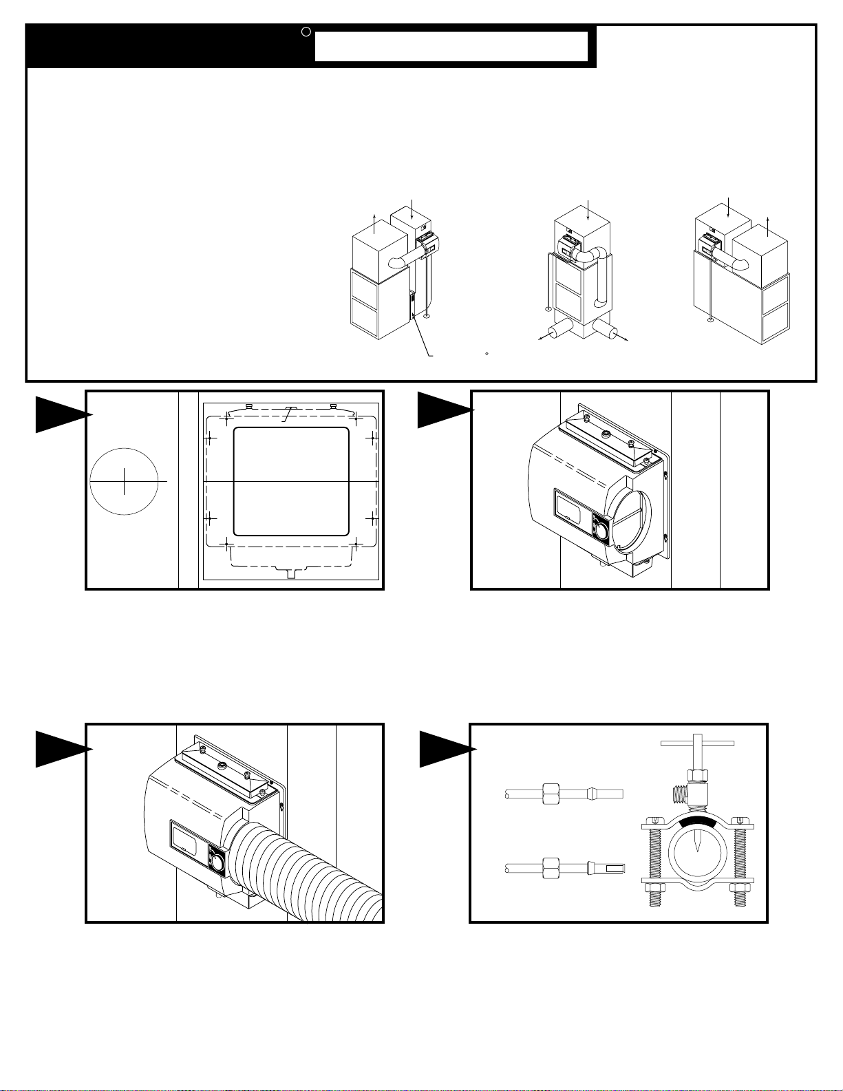
INSTALLATION: The humidifier may be mounted with
the 6" outlet to the right or left by inverting the cabinet and
reversing the positions of the distributor trough and drain
pan. The humidifier may be mounted on the warm or
return air plenum with equal efficiency.
See Typical Installations.
ADDITIONAL MATERIALS THAT MAY BE NECESSARY:
1. 1/4" diameter plastic supply tubing or 1/4" copper
supply tubing for hot water applications
2. 6" diameter galvanized by-pass pipe
3. electrical wire and wire nuts
4. air pressure switch (G.F. Model #12500 suggested)
2
1042 SERIES
FLOW-THROUGH
BYPASS HUMIDIFIER
R
3
COPPER
TUBING
PLASTIC
TUBING
Cut out center section of template and 6” hole. Hang humidifier cabinet
and insert remaining four screws. Tighten all 8 screws. Install
connecting collar after drilling 1/8” holes for screws. Connect by-pass
pipe to collar and humidifier cabinet. Using holes at top and bottom of
humidifier bypass opening drill 2---1/8" holes through bypass pipe and
screw by-pass pipe to humidifier cabinet.
Mount the self tapping saddle valve on either a cold or a hot water
pipe. A side or top mount is best to avoid clogging from pipe
sediment. Connect 1/4” O.D. tubing to the saddle valve. Copper
tubing requires a brass compression nut and brass sleeve. Plastic
tubing requires a brass insert inside the tubing, a plastic sleeve on
the outside with a brass compression nut.
NOTE: DO NOT USE PLASTIC TUBING ON HOT WATER OR IN
CONTACT WITH ANY HOT PLENUM SURFACE OR DUCT.
INSTALLATION OF THIS SADDLE VALVE MUST MEET OR
EXCEED LOCAL CODES AND ORDINANCES.
4
Select location on vertical surface of warm or return air plenum for
mounting humidifier. For plenum sizes 9 1/2" to 15" use 1040AD adapter
plate and five screws, 3 screws in top (supplied with DM model only).
Stick mounting template in place making sure the template is level. Do
not install humidifier or 6" bypass pipe where the blanked off ends of a
cooling coil will restrict air flow to the humidifier. Extend horizontal
centerline from template to the adjacent plenum. Scribe 6” circle 10” to
15” from side of humidifier, on cabinet centerline, using connecting collar
as guide.
Center punch the four side mounting holes on the template and drill
with an 1/8" drill bit. Insert four sheet metal screws in the side
mounting holes until the heads project about 3/8". Hang humidifier
from the four screws and install drain pan, evaporator pad and
distributor trough. Adjust humidifier until level and tighten four
screws. Remark four remaining holes if necessary. Remove
humidifier and drill four remaining holes.
Top Of Template
TEMPLATE FOR INSTALLING
BYPASS HUMIDIFIER
4. TIGHTEN SCREWS AND ADJUST HUMIDIFIER UNTIL LEVEL.
5. REMARK FOUR REMAINING HOLES IF NECESSARY.
6. REMOVE HUMIDIFIER, DRILL REMAINING HOLES AND CUT OUT CENTER SECTION OF
TEMPLATE.
WHEN INSTALLING ON BASEMENT TYPE FURNACE, EXTEND THIS LINE
FOR LOCATING HOLE ON ADJACENT PLENUM
IF FURNACE JACKET EXTENDS MORE THAN 3" OUTWARD FROM THE PLENUM SURFACE
ALLOW 4" CLEARANCE BELOW THIS LINE FOR EASY ACCESS TO DRAIN HOSE CONNECTION.
CUT ON THIS LINE
TEMPLATE NO. 1042-25
ALLOW 2 1/2 INCHES CLEARANCE
ABOVE THIS SURFACE FOR SERVICING
FOLLOW INSTRUCTIONS PACKED WITH HUMIDIFIER
1. REMOVE PROTECTIVE PAPER FROM BACK OF TEMPLATE AND STICK IN LEVEL POSITION.
2. CENTER PUNCH AND DRILL THE FOUR SIDE MOUNTING HOLES WITH A 1/8 " DIA. DRILL.
3. HANG HUMIDIFIER FROM FOUR SIDE SCREWS AND INSTALL DRAIN PAN, EVAPORATOR
PAD AND DISTRIBUTOR TROUGH.
HIGH BOY COUNTER-FLOW LOW BOY
RETURN AIR
RETURN AIR
RETURN AIR
WARM AIR
WARM AIR
WARM AIR
WARM AIR
GENERALAire
AC SERIES
HIGH EFFICIENCY AIR CLEANER
R
DRAIN
DRAIN
DRAIN
Page 2
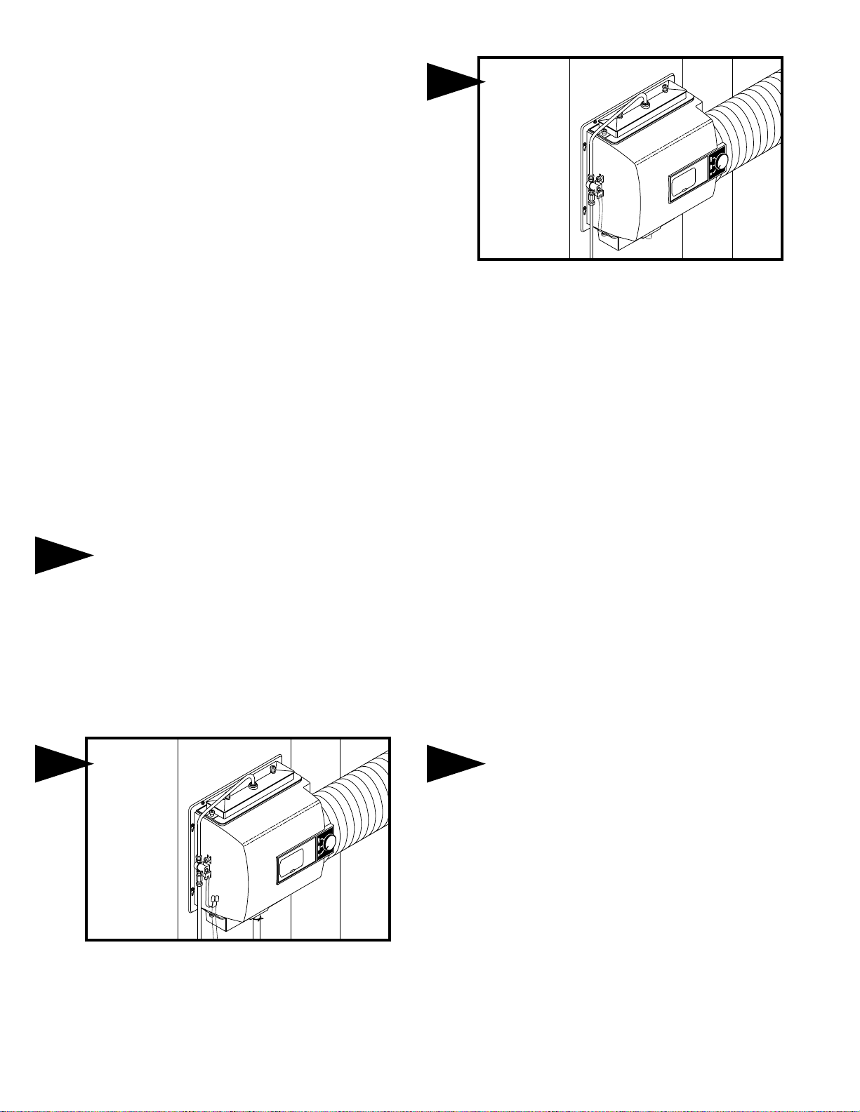
Attach solenoid valve to side of humidifier cabinet with flow arrow
pointing up, using thumb nuts provided. Do not reverse brass
fittings as valve will not function if flow is reversed. Assemble
distributor tube so that it is directed into the center opening of the
distributor trough cover. Connect 1/4" water supply tube to brass
filter at inlet of solenoid.
DO NOT USE PLASTIC TUBING IN
CONTACT WITH ANY HOT PLENUM SURFACE OR
DUCT. IF USING PLASTIC TUBING, USE TUBE
SUPPORT PROVIDED.
SADDLE VALVE INSTALLATION INSTRUCTIONS
Copper Pipe
1. Retract piercing pin into valve body by turning handle
counterclockwise.
2. Screw valve body into upper bracket and tighten.
3. Place rubber gasket over piercing pin.
4. Assemble saddle valve over copper pipe using enclosed screws,
nuts and lower bracket.
5. Tighten screws evenly and firmly. Brackets should be parallel.
6. Complete compression connection to saddle valve outlet.
7. Turn handle clockwise to pierce tubing and close saddle valve.
8. Turn handle counterclockwise to
open saddle valve, leave open for
several seconds to flush dirt from pipe and tubing.
Steel, Brass or Hard Plastic Pipe
1. Shut off water supply and drain pipe.
2. Turn handle clockwise to expose piercing pin and close saddle
valve.
3. Place rubber gasket over piercing pin.
4. Drill 1/8" hole in pipe using a hand crank drill to avoid shock hazard.
5. Assemble saddle valve over steel, brass or hard plastic pipe using
enclosed screws, nuts and lower bracket.
6. Tighten screws evenly and firmly. Brackets should be parallel.
7. Complete compression connection to saddle valve outlet.
8. Turn handle counterclockwise to
open saddle valve, leave open for
several seconds to flush dirt from pipe and tubing.
Threaded Pipe Fittings
1. Turn handle clockwise to expose piercing pin and close saddle
valve.
2. Seal valve body threads using pipe tape or sealant.
3. Install valve into 1/8" NPT fitting.
4. Complete compression connection to saddle valve outlet.
5. Turn handle counterclockwise to
open saddle valve, leave open for
several seconds to flush dirt from pipe and tubing.
Turn on water supply and check operation of humidifier. Set humidistat to
a demand setting. With the furnace off, the solenoid valve should be
closed. Start the furnace, the solenoid valve should open when the
blower or burner circuit is energized. Check flow of water through
distributor trough and evaporator pad. The standard 990-16-76 orifice will
supply approximately 3.5 GPH of water at a line water pressure of 60 psi.
For low water pressures (20-40 psi) a larger orifice 990-16-75 is available
to provide the same flow. Leave humidistat set at the recommended
setting.
Connect drain hose to 5/8" spout on humidifier cabinet using hose
clamp provided. Run 5/8" hose to suitable drain such as floor drain,
sewer or laundry sink. Be sure hose has continuous slope and is not
kinked at any point.
7 8
5
6
WIRING
Please refer to the installation instructions included with the Humidistat.
GENERALAire
Sélectionner un emplacement sur la surface verticale d'un plénum d'air chaud ou
de retour d'air pour monter l'humidificateur. Pour les plénums de 9 1/2 po à to 15
po, utiliser la plaque adaptatrice 1040AD et les 5 vis, 3 vis en haut (modèle DM).
Mettre la matrice de montage en place en s'assurant qu'elle soit à niveau. Ne
pas installer l'humidificateur ou le tuyau de dérivation de 15 cm (6 po) à l'endroit
où l'extrémité de la plaque d'obturation d'un serpentin refroidisseur pourra
restreindre le débit d'air vers l'humidificateur. Prolonger la ligne horizontale
depuis le milieu du gabarit jusqu’à la chambre à air voisine. Marquer un cercle
de 6 po à une distance de 10 à 15 po du côté de l'humidificateur, sur la ligne
centrale du boîtier, à l'aide d'un collier de raccordement pour guider.
Page 3

PARTS LIST FOR HUMIDIFIER
1099-9 THUMB NUT
1137-35 TROUGH COVER
1137-4 DISTRIBUTOR TROUGH
1042-5 DISTRIBUTOR TUBE
990-13 EVAPORATOR PAD
CABINET ASSEMBLY
1042-16 (24 V.)
P-103 COMPRESSION NUT
P-104 COMPRESSION SLEEVE
P-111 CONNECTOR
SOLENOID VALVE ASSEMBLY
990-53 (24 V.)
990-37-76 ORIFICE & STRAINER
ASSEMBLY
990-16-76 ORIFICE FITTING
990-17 STRAINER SCREEN
990-18 STRAINER BODY
1137-3 DRAIN PAN
P-163 HOSE CLAMP
1099-16 DRAIN TUBE
GENERALAire
RESIDENTIAL AIR TREATMENTPRODUCTS
R
FILL OUT AND MAIL THIS
WARRANTY CARD AND
LITERATURE REQUEST FORM
AIRC
H
D
AIRF
F
A
LEANERS AND AIRPURIFIERS
UMIDIFIERS
IGITALHUMIDITYGAGE
ILTERGAGE
UELOILFILTERS AND
CCESSORIES
FORM NO. 1042-29 (FILE 10120) REV. B
Litho in U.S.A.
Page 4

LIMITED WARRANTY
This humidifier, if properly registered by the return of the warranty registration card to the manufacturer, is warranted to the consumer against defects in
materials and workmanship for a period of one year from the date of installation. Evaporator pads, sleeves or plates are not covered by this limited
warranty or any other warranties. Any other defective parts will be repaired without charge except for removal, reinstallation and transportation costs. To
obtain repair service under this limited warranty, the consumer must send the defective part or the complete humidifier to the manufacturer.
THERE ARE NO EXPRESS WARRANTIES COVERING THIS HUMIDIFIER OTHER THAN AS SET FORTH ABOVE, THE IMPLIED WARRANTIES OF
MERCHANTABILITY AND FITNESS FOR A PARTICULAR PURPOSE ARE LIMITED IN DURATION TO ONE YEAR. THE MANUFACTURER
ASSUMES NO LIABILITY IN CONNECTION WITH THE INSTALLATION OR USE OF THIS PRODUCT, EXCEPT AS STATED IN THIS LIMITED
WARRANTY. THE MANUFACTURER WILL IN NO EVENT BE LIABLE FOR INCIDENTAL OR CONSEQUENTIAL DAMAGES.
This limited warranty gives you specific legal rights, and you may also have other rights which vary from state to state. Some states do not allow either
limitations on implied warranties, or exclusions from incidental or consequential damages, so the above exclusion and limitation may not apply to you.
Any questions pertaining to this limited warranty should be addressed to the manufacturer. (U.S.A.: The manufacturer has elected not to make available
the informal dispute settlement mechanism which is specified in the Magnuson-Moss Warranty Act.)
GENERAL FILTERS, INC. 43800 GRAND RIVER AVE. NOVI, MICHIGAN 48375-1115 WWW.GENERALAIRE.COM
CANADIAN GENERAL FILTERS, LTD. 39 CROCKFORD BLVD. SCARBOROUGH, ONTARIO M1R3B7 WWW.CGFPRODUCTS.COM
CARE AND MAINTENANCE
Your Humidifier is engineered to give helpful and trouble-free humidification. For maximum efficiency the following cleaning procedures should be carried
out at the end of each heating season:
1. Turn off water supply and electrical power to humidifier.
2. Remove water distributor tube, distributor trough, evaporator pad and drain pan. The evaporator pad may be
removed from either the top or bottom of the humidifier. Clean excessive mineral deposits from the distributor trough,
cover, drain pan and humidifier cabinet. A solution of 1/2 vinegar & 1/2 water will help loosen mineral deposits.
3. If the evaporator pad has excessive mineral deposits, replace with a new “990-13” evaporator pad. Install trough
and drain pan. Replace cover and the distributor tube to proper position over the distributor trough.
4. In heavy mineral areas or if the solenoid valve fails to function disconnect the 1/4” water supply line from the
solenoid valve. Remove the brass strainer body (P.N. 990-18) from the solenoid valve. Carefully pull the strainer
screen (P.N. 990-17) from the orifice fitting (P.N. 990-16). Clean the mineral deposits from all parts. If the orifice is
clogged, it may be opened by inserting a small needle. Reinsert the filter into the orifice fitting and screw the brass
strainer body into the solenoid valve.
5. Reconnect the 1/4” water line to the solenoid valve if necessary. Turn on the water supply and check all points for
leakage. The operation of the unit may be checked by starting the furnace. The humidifier operates only when the
furnace blower is running or the burner circuit is energized. The humidifier is now ready for operation.
6. During the summer, turn off water supply and electrical power to humidifier. Close air damper.
AT
OUTSIDE
TEMPERATURE
RECOMMENDED
SETTING
-20ϒF -29ϒC 15%
-10ϒF -23ϒC 20%
0ϒF -18ϒC 25%
+10ϒF -29ϒC
+20ϒF - 7ϒC
30%
35%
+30ϒF - 1ϒC 40%
D
D
Ville:
ATE OF
ATE DE
I
I
NSTALLATION
NSTALLATION
Province:
S
N
ERIAL
UMÉRO DE
N
UMBER
S
ÉRIE
Code postal:
Adresse:
C
ITY
S
TATE
P
OSTAL
C
ODE
LE PROPRIÉTAIRE DOIT REMPLIR LA CARTE
D'ENREGISTREMENT ET LA POSTER AU :
OWNER REGISTER ONLINE AT WWW.GENERALAIRE.COM OR
FILL IN REGISTRATION
AND MAIL TO:
D
Nom du marchand:
S
EALER'S
TREET
A
DDRESS
N
AME
Adresse:
C
Ville:
ITY
S
Province:
TATE
P
Code postal:
OSTAL
C
ODE
O
Nom du propriétaire:
S
TREET
A
DDRESS
MODÈLE 1042LH
WNER'S NAME
MODÈLE 1042E
MODÈLE 1042DM
WARRANTY REGISTRATION
Enregistrement de la garantie
MODEL 1042LH
GENERAL FILTERS, INC.
43800 GRAND RIVER AVE
NOVI, MI 48375-1115
MODEL 1042E
MODEL 1042DM
HOW THE HUMIDIFIER WORKS
The operating principle of the humidifier is based on the most efficient
and economical means of evaporating water to the air. The humidifier
uses only six watts of electrical power during operation, less than the
smallest household light bulb. The heat necessary for evaporating
water is produced by the furnace.
The water supply to the humidifier is controlled by the electric solenoid
valve. The humidistat connected in series with the solenoid
low voltage control of the humidifier. The humidistat is designed for
wall mounting in the living area or surface mounting on the return air
duct. ELECTRICAL RATING: 24 VAC / 60 Hz. DO NOT SET
RELATIVE HUMIDITY TOO HIGH DURING COLD WEATHER.
EXCESSIVE HUMIDITY MAY CAUSE CONDENSATION ON
WINDOWS OR IN WALLS. REFER TO RECOMMENDED SETTINGS
AS DESCRIBED IN THE HUMIDISTAT OWNERS MANUAL.
Water flows through a strainer, is metered through an orifice to provide
the proper amount of water, and is supplied to the evaporator pad by
the distributor trough. Approximately 200 CFM of air is by-passed from
the warm air plenum through the humidifier and returned to the cold air
plenum. Moisture is evaporated to the air passing through the
evaporator pad.
Minerals are not blown into the air stream as occurs in atomizing
humidifiers; they are left on the evaporator pad where a high
percentage is carried off with the waste water.
When the humidifier is installed and operating, no adjustments are
necessary other than setting the control knob on the humidistat to the
desired level of humidification. Leave knob on the humidifier in "HI" or
"WINTER" position.
To turn the humidifier off, close water supply valve, switch electrical
power off and turn humidistat off. If furnace is used for summer cooling
or ventilating set air damper on "LOW" or "SUMMER".
provides
 Loading...