


JGS968BEK4BB
GE JGS968BEK4BB, JGS968SEK4SS, JGS968TEK4WW, PGS968BEM2BB, PGS968BEM3BB Installation Guide
...
IIlnstallation I Gas Slide-In Rangel
nstructions JGS905, JGS968, PGS968
Ir_ Questions? Call 800.GE.CARES (800.432.2737) or Visit our Website at: ge.comIn Canada, call 1.800.361.3400 or Visit our Website at: www.geappliances.ca I
IN THE COMMONWEALTH OF
MASSACHUSETTS:
• This product must be installed by a
licensed plumber or gas fitter.
• When using ball-type gas shut-off valves,
they shall be the T-handle type.
• A flexible gas connector, when used, must
not exceed 3 feet.
BEFORE YOU BEGIN
Read these instructions completely
and carefully.
• IMPORTANT - Savethese
instructions for local inspector's use.
• IMPORTANT - Observeall
governing codes and ordinances.
• Note to Installer - Be sure to leave these
instructions with the Consumer.
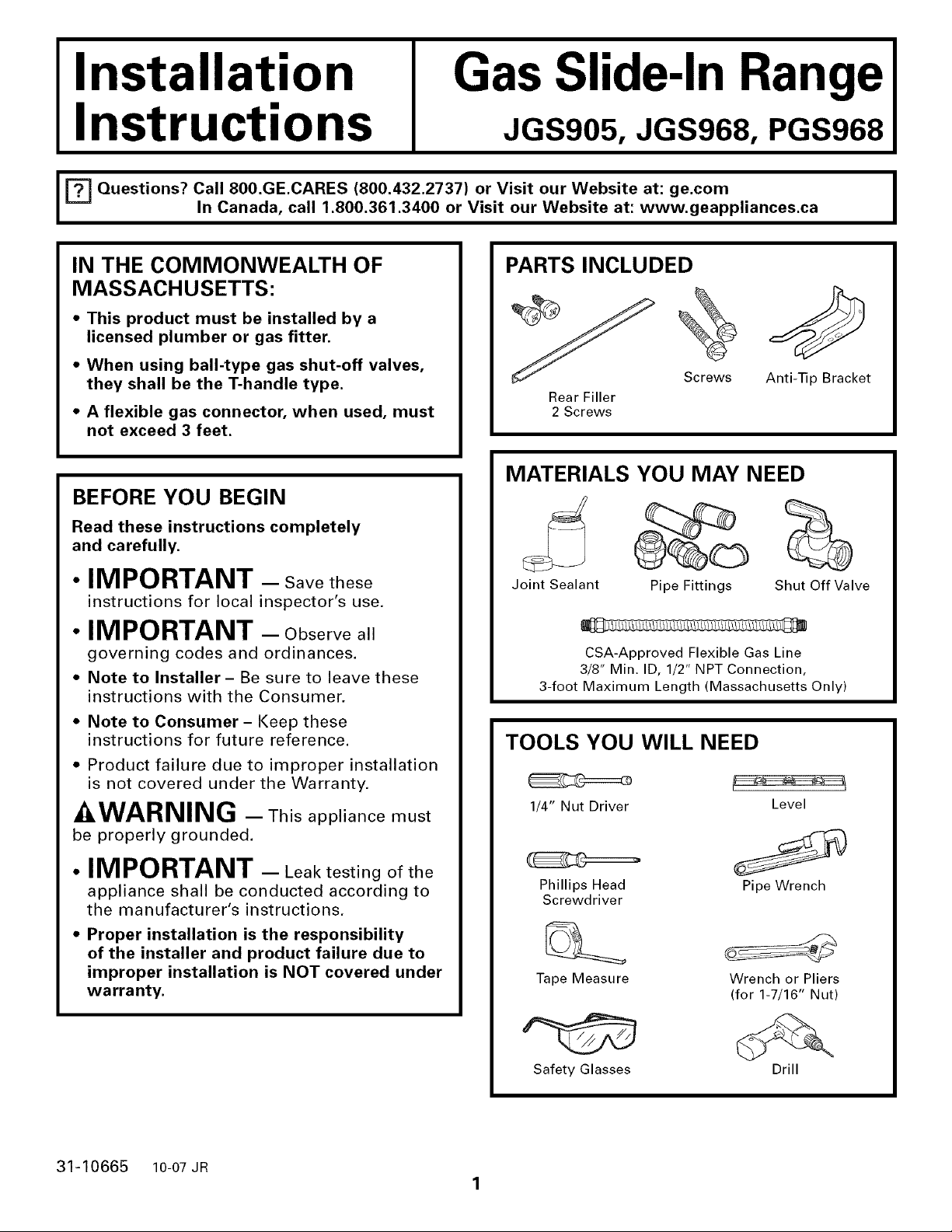
PARTS INCLUDED
Screws
Rear Filler
2 Screws
Anti-Tip Bracket
MATERIALS YOU MAY NEED
Joint Sealant Pipe Fittings Shut Off Valve
CSA-Approved Flexible Gas Line
3/8" Min. ID, 1/2" NPT Connection,
3-foot Maximum Length (Massachusetts Only)
• Note to Consumer - Keep these
instructions for future reference.
• Product failure due to improper installation
is not covered under the Warranty.
-&WARNING - This appliance must
be properly grounded.
• IMPORTANT - Leak testing of the
appliance shall be conducted according to
the manufacturer's instructions.
• Proper installation is the responsibility
of the installer and product failure due to
improper installation is NOT covered under
warranty.
31-10665 10-07 JR
TOOLS YOU WILL NEED
1/4" Nut Driver
Phillips Head
Screwdriver
Tape Measure
Safety Glasses
1
Level
Pipe Wrench
Wrench or Pliers
(for 1-7/16" Nut)
Drill
Installation Instructions
IMPORTANT SAFETY INSTRUCTIONS
FOR YOUR SAFETY:
WARNING - Iftheinformationin
this manual is not followed exactly, a fire,
explosion or gas leak may result causing
property damage, personal injury or death.
Do not store or use gasoline or other
flammable vapors and liquids in the vicinity
of this or any other appliance!
WHAT TO DO IF YOU
SMELL GAS:
• Do not try to light any appliance. Do not
touch any electrical switch; do not use any
phone in your building.
• Immediately call your gas supplier from a
neighbor's phone. Follow the gas supplier's
instructions.
• If you cannot reach your gas supplier, call
the fire department.
This range has been design certified by
UNDERWRITERS LABORATORIES for use in
the United States and Canada. You'll find
safety precautions in your Owner's Manual.
Read them carefully.
• Installation of this range must conform with
local codes or in the absence of local codes
with the National Fuel Gas Code, ANSI
Z223.1-Latest edition.
Be sure your range is installed properly by
a qualified installer or service technician.
To eliminate reaching over surface burners,
cabinet storage above burner should be
avoided.
• Do not install the unit near an outside door
or where a draft may affect its use.
Installation and service must be performed by
a qualified installer, service agency or the gas
supplier.
Installation Instructions
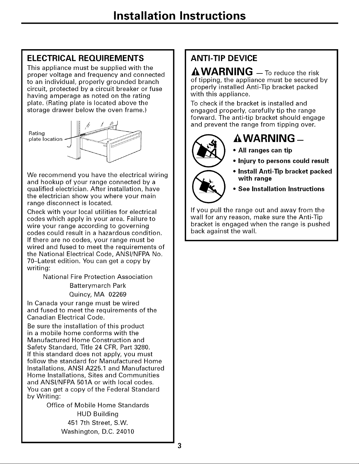
ELECTRICAL REQUIREMENTS
This appliance must be supplied with the
proper voltage and frequency and connected
to an individual, properly grounded branch
circuit, protected by a circuit breaker or fuse
having amperage as noted on the rating
plate. (Rating plate is located above the
storage drawer below the oven frame.)
Rating
plate location
We recommend you have the electrical wiring
and hookup of your range connected by a
qualified electrician. After installation, have
the electrician show you where your main
range disconnect is located.
Check with your local utilities for electrical
codes which apply in your area. Failure to
wire your range according to governing
codes could result in a hazardous condition.
If there are no codes, your range must be
wired and fused to meet the requirements of
the National Electrical Code, ANSI/NFPA No.
70-Latest edition. You can get a copy by
writing:
National Fire Protection Association
Batterymarch Park
Quincy, MA 02269
In Canada your range must be wired
and fused to meet the requirements of the
Canadian Electrical Code.
Be sure the installation of this product
in a mobile home conforms with the
Manufactured Home Construction and
Safety Standard, Title 24 CFR, Part 3280.
If this standard does not apply, you must
follow the standard for Manufactured Home
Installations, ANSI A225.1 and Manufactured
Home Installations, Sites and Communities
and ANSl/NFPA 501A or with local codes.
You can get a copy of the Federal Standard
by Writing:
Office of Mobile Home Standards
HUD Building
451 7th Street, S.W.
Washington, D.C. 24010
ANTI-TIP DEVICE
AWARNING - Toreducetherisk
of tipping, the appliance must be secured by
properly installed Anti-Tip bracket packed
with this appliance.
To check if the bracket is installed and
engaged properly, carefully tip the range
forward. The anti-tip bracket should engage
and prevent the range from tipping over.
AWARNING-
• All ranges can tip
• Injury to persons could result
• Install Anti-Tip bracket packed
with range
• See Installation Instructions
If you pull the range out and away from the
wall for any reason, make sure the Anti-Tip
bracket is engaged when the range is pushed
back against the wall.

Installation Instructions
PRE-INSTALLATION CHECKLIST
_-I INSPECT INSTALLATION
LOCATION
Refer to alternate construction section for
the following non-standard installations.
[] Counter opening extends to the wall:
Maintop Filler (supplied with the
range.) (See page 15 for Installation
Instructions) or
Backguard (Kit JXS36XX or JXS39SS).
[] Counter height greater than 36-314":
Lower Trim Slide-In (Kit JXS56XX).
[] One side is not enclosed by a cabinet:
Bodyside (Kit JXS76XX).
[] Island Installation:
To provide an optimum installation, the
top surface of the countertop must be
level and flat (lie on the same plane)
around the 3 sides that are adjacent to
range cooktop, Proper adjustments to
make the top flat should be made or
gaps between the countertop and
range cooktop may occur. Forcing the
cooktop to fit may cause excessive
gaps and could break the glass and
void the warranty.
_-I MOVE RANGE INDOORS IN
FRONT OF CABINET OPENING
Do not use hand trucks when moving the
unpackaged range. Cooktop glass may be
broken.
[] PROTECT THE KITCHEN
FLOOR
Flatten and place a piece of the shipping
carton in front of the installation location to
protect the flooring.
NOTE: Do not remove the protective
channel from the sides of the glass cooktop,
if applicable, until later in the installation.
Protective
Channel
To obtain Kits:
a. Visit GE Web Site (See page 1)
b. Call GE Answer Center (See page 1)
c. Contact Dealer
_-I CAREFULLY, TILT RANGE TO
ACCESS RANGE LEVELING
LEGS
Use an adjustable wrench to screw leveling
legs out so that glass support flanges clear
top of countertop.
4
Installation Instructions
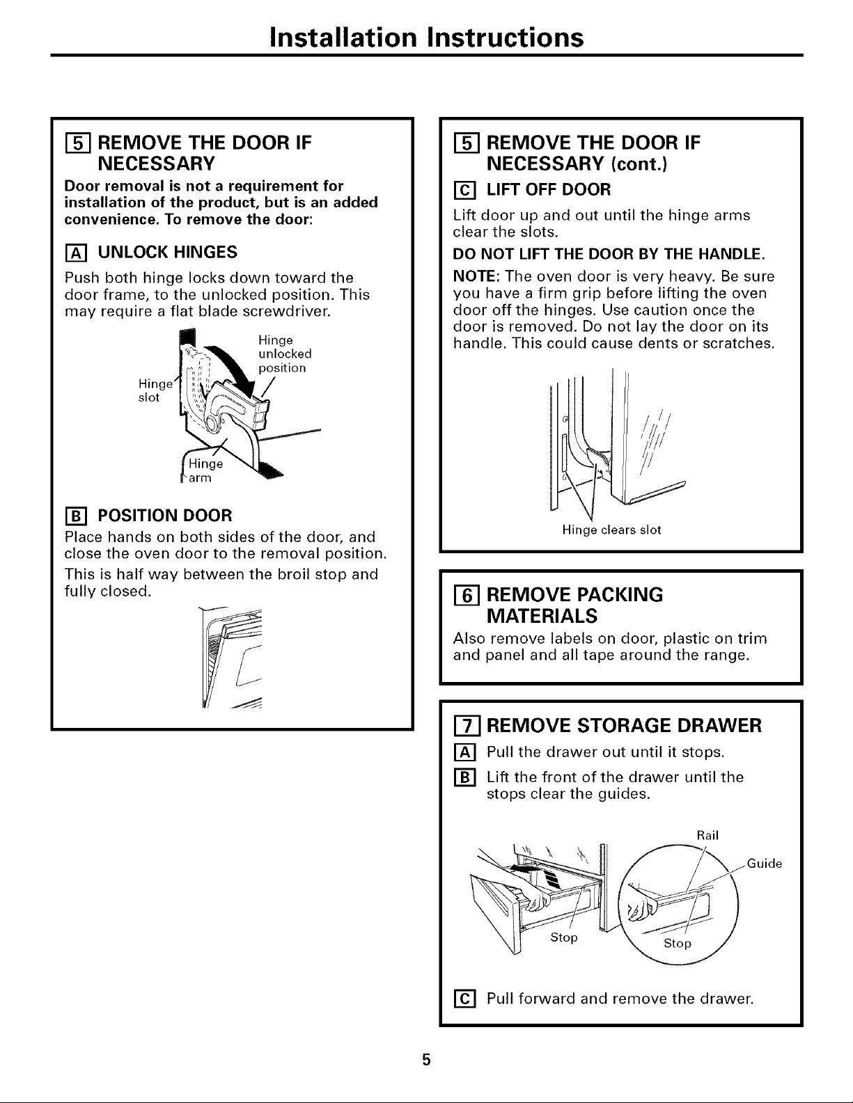
[] REMOVE THE DOOR IF
NECESSARY
Door removal is not a requirement for
installation of the product, but is an added
convenience, To remove the door:
[] UNLOCK HINGES
Push both hinge locks down toward the
door frame, to the unlocked position. This
may require a flat blade screwdriver.
Hinge
unlocked
position
Hinge' /
slot
arm
[] POSITION DOOR
Place hands on both sides of the door, and
close the oven door to the removal position.
This is half way between the broil stop and
fully closed.
REMOVE THE DOOR IF
NECESSARY (cont.)
[] LIFT OFF DOOR
Lift door up and out until the hinge arms
clear the slots.
DO NOT LIFT THE DOOR BY THE HANDLE.
NOTE: The oven door is very heavy. Be sure
you have a firm grip before lifting the oven
door off the hinges. Use caution once the
door is removed. Do not lay the door on its
handle. This could cause dents or scratches.
Hinge clears slot
REMOVE PACKING
MATERIALS
Also remove labels on door, plastic on trim
and panel and all tape around the range.
[] REMOVE STORAGE DRAWER
[] Pull the drawer out until it stops.
[] Lift the front of the drawer until the
stops clear the guides.
Rail
Stop
[] Pull forward and remove the drawer.
Installation Instructions
PRE-INSTALLATION CHECKLIST (CONT.)
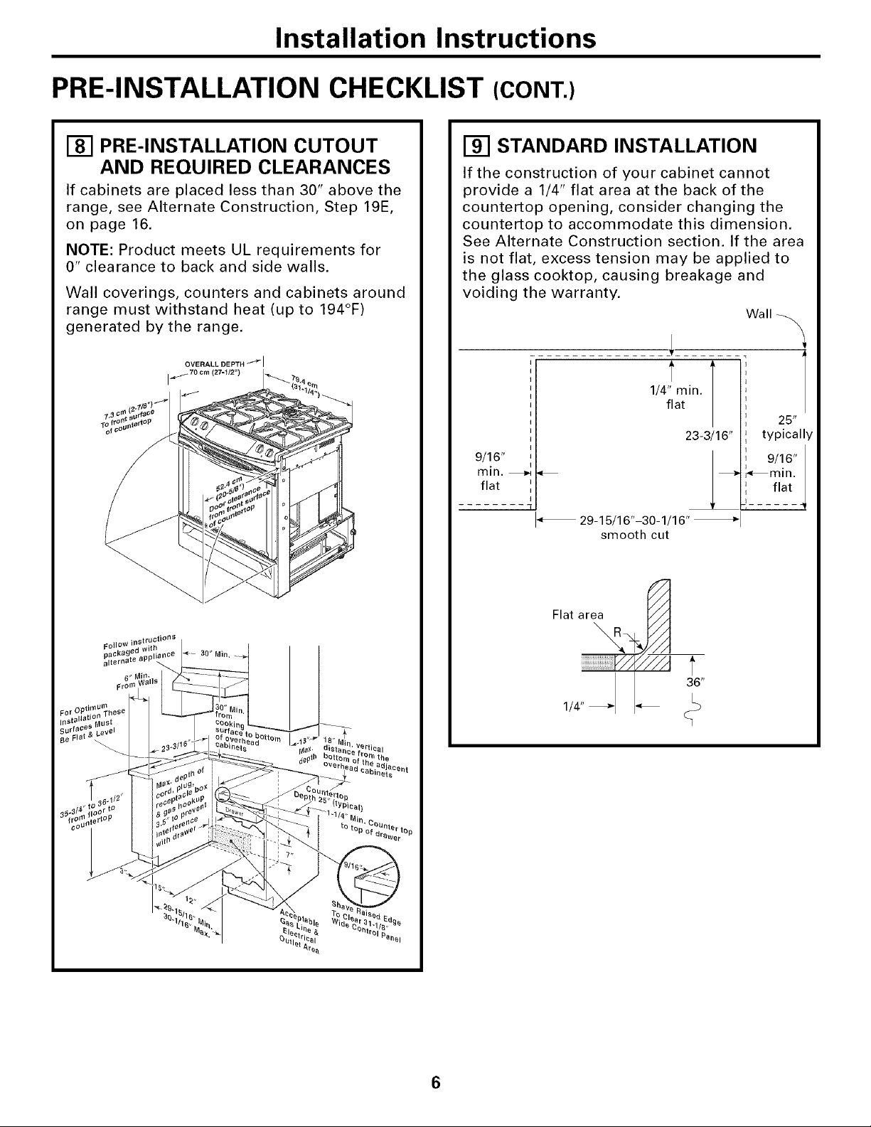
[] PRE-INSTALLATION CUTOUT
AND REQUIRED CLEARANCES
If cabinets are placed less than 30" above the
range, see Alternate Construction, Step 19E,
on page 16.
NOTE: Product meets UL requirements for
0" clearance to back and side walls.
Wall coverings, counters and cabinets around
range must withstand heat (up to 194°F)
generated by the range.
STANDARD INSTALLATION
If the construction of your cabinet cannot
provide a 1/4" flat area at the back of the
countertop opening, consider changing the
countertop to accommodate this dimension.
See Alternate Construction section. If the area
is not flat, excess tension may be applied to
the glass cooktop, causing breakage and
voiding the warranty.
Wall _._
1/4" min.
flat
25"
23-3/16"
9/16"
min.
flat
I
" 29-15/16"-30-1/16" _1
smooth cut
typically
9/16"
_min.
flat
-i ...... 4
FollOW
packa 30" Min,
Flat area
1/4" _ I_ _36"
I
6
Installation Instructions
ELECTRICAL CONNECTIONS
INSTALLATIONmELECTRICAL
[]
CONNECTIONS
Because of potential safety hazards
[]
under certain conditions, we strongly
recommend against the use of an
extension cord. However, if you still
elect to use an extension cord, it is
absolutely necessary that it is a UL
listed 3-wire grounding-type appliance
extension cord and that the current
carrying rating of the cord in amperes
is equivalent to or greater than the
branch circuit rating. Such extension
cords are obtainable through your local
appliance dealer.
IMPORTANT: (Please read carefully)
FOR PERSONAL SAFETY, THIS
APPLIANCE MUST BE PROPERLY
GROUNDED.
[] An adequate electrical supply and
outlet must be used to operate the
electrical parts of your range.
• The power cord of this appliance is
equipped with a three-prong (grounding)
plug which must be used with a properly
grounded three-hole outlet with standard
120 Volt, 60 cycle AC household current.
• When a standard two-prong wall
receptacle is encountered, it is the
personal responsibility and obligation
of the customer to have it replaced with
a properly grounded three-prong wall
receptacle by a qualified electrician.
Do not under any circumstances cut or
remove grounding prong from the range
cord. Failure to provide proper ground may
create a hazardous condition.
Installation Instructions
GAS CONNECTIONS
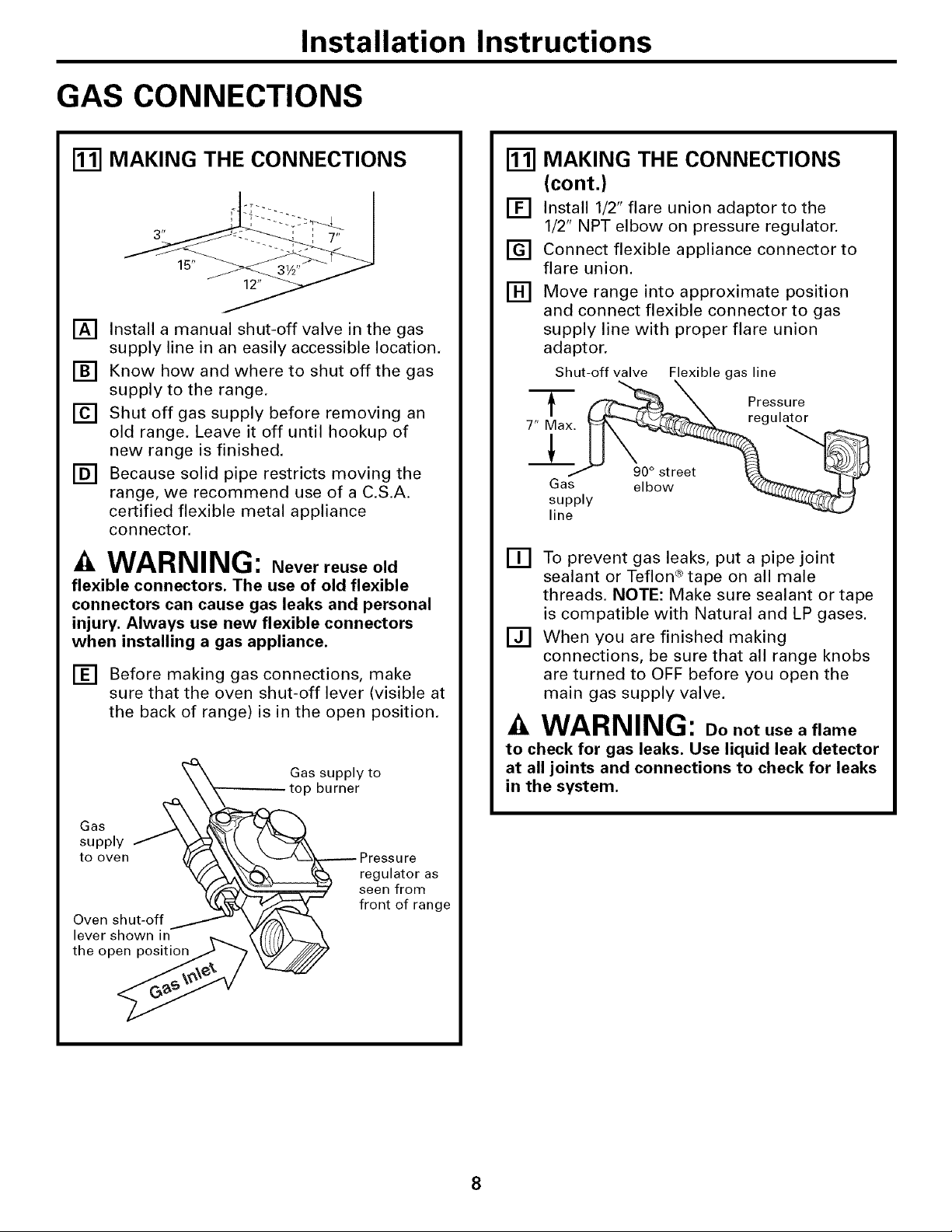
_] MAKING THE CONNECTIONS
15"
[]
Install a manual shut-off valve in the gas
supply line in an easily accessible location.
[]
Know how and where to shut off the gas
supply to the range.
[]
Shut off gas supply before removing an
old range. Leave it off until hookup of
new range is finished.
[]
Because solid pipe restricts moving the
range, we recommend use of a C.S.A.
certified flexible metal appliance
connector.
WARNING: Never reuse old
flexible connectors. The use of old flexible
connectors can cause gas leaks and personal
injury. Always use new flexible connectors
when installing a gas appliance.
[] Before making gas connections, make
sure that the oven shut-off lever (visible at
the back of range) is in the open position.
Gas supply to
top burner
_] MAKING THE CONNECTIONS
(cont.)
[] Install 1/2" flare union adaptor to the
1/2" NPT elbow on pressure regulator.
[] Connect flexible appliance connector to
flare union.
[] Move range into approximate position
and connect flexible connector to gas
supply line with proper flare union
adaptor.
Shut-off valve Flexible gas line
T __ Pressure
Gas elbow _ U
supply "_444_4_7_,(_
line
[] To prevent gas leaks, put a pipe joint
sealant or Teflon ®tape on all male
threads. NOTE: Make sure sealant or tape
is compatible with Natural and LP gases.
[] When you are finished making
connections, be sure that all range knobs
are turned to OFF before you open the
main gas supply valve.
-&WARNING: Do not use a flame
to check for gas leaks. Use liquid leak detector
at all joints and connections to check for leaks
in the system.
Gos
supply _X_ _{
tooven
Oven shut-off _ _
lever shown in
the op_
_ Pr;s_utr:r as
seen from
front of range
8
Installation Instructions
INSTALL THE RANGE
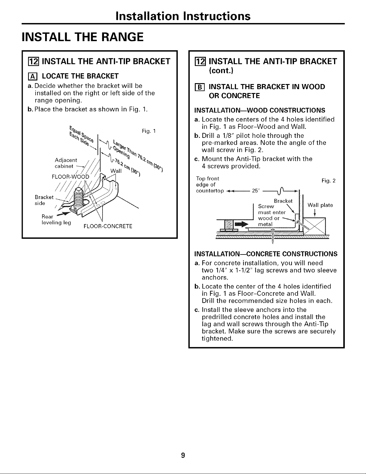
r_ INSTALL THE ANTI-TIP BRACKET
[] LOCATE THE BRACKET
a. Decide whether the bracket will be
installed on the right or left side of the
range opening.
b. Place the bracket as shown in Fig. 1,
Fig. 1
Adjacent
cabinet
/
FLOOR-CONCRETE
Bracket
side
Rear
leveling leg
FLOOR-WOOD
/
[] INSTALL THE ANTI-TIP BRACKET
(cont.)
[] INSTALL THE BRACKET IN WOOD
OR CONCRETE
INSTALLATION--WOOD CONSTRUCTIONS
a. Locate the centers of the 4 holes identified
in Fig. 1 as Floor-Wood and Wall.
b. Drill a 1/8" pilot hole through the
pre-marked areas. Note the angle of the
wall screw in Fig. 2.
c. Mount the Anti-Tip bracket with the
4 screws provided,
Top front Fig. 2
edge of
countertop _ 25" _,f_'="_l
Bracket_lll
I Screw \\ I1 Wall plate
INSTALLATION--CONCRETE CONSTRUCTIONS
a. For concrete installation, you will need
two 1/4" x 1-1/2" lag screws and two sleeve
anchors.
b. Locate the center of the 4 holes identified
in Fig. 1 as Floor-Concrete and Wall,
Drill the recommended size holes in each.
Install the sleeve anchors into the
C,
predrilled concrete holes and install the
lag and wall screws through the Anti-Tip
bracket. Make sure the screws are securely
tightened.
Installation Instructions
INSTALL THE RANGE (CONT.)
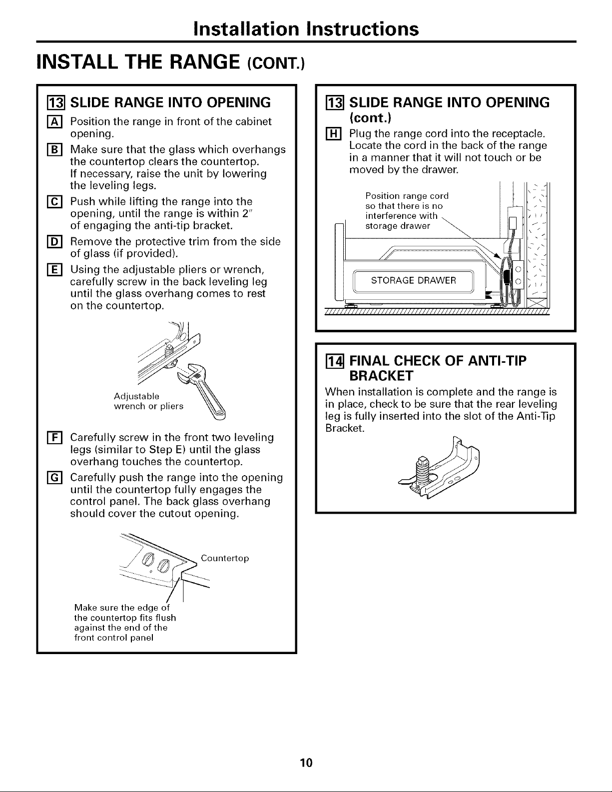
SLIDE RANGE INTO OPENING
[]
[]
Position the range in front of the cabinet
opening.
[] Make sure that the glass which overhangs
the countertop clears the countertop.
If necessary, raise the unit by lowering
the leveling legs.
[] Push while lifting the range into the
opening, until the range is within 2"
of engaging the anti-tip bracket.
[] Remove the protective trim from the side
of glass (if provided).
[] Using the adjustable pliers or wrench,
carefully screw in the back leveling leg
until the glass overhang comes to rest
on the countertop.
r_ SLIDE RANGE INTO OPENING
(cont.)
[] Plug the range cord into the receptacle.
Locate the cord in the back of the range
in a manner that it will not touch or be
moved by the drawer.
/////
\
/I/
\ //
\
/11
j _
i \
j _
Position range cord
so that there is no
interference with
\
[] Carefully screw in the front two leveling
legs (similar to Step E) until the glass
overhang touches the countertop.
[] Carefully push the range into the opening
until the countertop fully engages the
control panel. The back glass overhang
should cover the cutout opening.
Counte_op
Make sure the edge of
the countertop fits flush
against the end of the
front control panel
r_-z-4]FINAL CHECK OF ANTI-TIP
BRACKET
When installation is complete and the range is
in place, check to be sure that the rear leveling
leg is fully inserted into the slot of the Anti-Tip
Bracket.
10
 Loading...