

Page 1
G600
Pilot’s
Guide
Page 2

© 2011 Garmin Ltd. or its subsidiaries. All rights reserved.
This manual reflects the operation of System Software version 6.00, or later. Some differences in operation
may be observed when comparing the information in this manual to later software versions.
Garmin International, Inc., 1200 East 151st Street, Olathe, KS 66062, U.S.A.
Tel: 913/397.8200 Fax: 913/397.8282
Garmin AT, Inc., 2345 Turner Road SE, Salem, OR 97302, U.S.A.
Tel: 503/391.3411 Fax 503/364.2138
Garmin (Europe) Ltd., Liberty House, Bulls Copse Road, Hounsdown Business Park, Southampton,
SO40 9RB, U.K.
Tel. +44 (0) 870 850 1243 Fax +44 (0) 238 052 4004
Garmin Corporation, No. 68, Jangshu 2nd Road, Shijr, Taipei County, Taiwan
Tel: 886/02.2642.9199 Fax: 886/02.2642.9099
At Garmin, we value your opinion. For comments about this guide, please e-mail:
Techpubs.Salem@Garmin.com
www.garmin.com
Except as expressly provided herein, no part of this manual may be reproduced, copied, transmitted,
disseminated, downloaded or stored in any storage medium, for any purpose without the express written
permission of Garmin. Garmin hereby grants permission to download a single copy of this manual and of
any revision to this manual onto a hard drive or other electronic storage medium to be viewed for personal
use, provided that such electronic or printed copy of this manual or revision must contain the complete text
of this copyright notice and provided further that any unauthorized commercial distribution of this manual
or any revision hereto is strictly prohibited.
Garmin®, FliteCharts®, and SafeTaxi® are registered trademarks of Garmin Ltd. or its subsidiaries. SVT™,
and G600™ are trademarks of Garmin Ltd. or its subsidiaries. These trademarks may not be used without
the express permission of Garmin.
NavData® is a registered trademark of Jeppesen, Inc.; SkyWatch® is a registered trademark of L-3 Avionics
Systems; and XM® is a registered trademark of XM Satellite Radio, Inc.; Iridium® is a registered trademark
of Iridium Communications Inc.; Canadian radar data provided by Environment Canada; United States
radar data provided by NOAA; European radar data collected and provided by Meteo France.
August 2011 Printed in the U.S.A.
Page 3

AVIATION LIMITED WARRANTY
All Garmin avionics products are warranted to be free from defects in materials or workmanship for:
two years from the date of purchase for new Remote-Mount and Panel-Mount products; one year
from the date of purchase for new portable products and any purchased newly-overhauled products;
six months for newly-overhauled products exchanged through a Garmin Authorized Service Center;
and 90 days for factory repaired or newly-overhauled products exchanged at Garmin in lieu of repair.
Within the applicable period, Garmin will, at its sole option, repair or replace any components that
fail in normal use. Such repairs or replacement will be made at no charge to the customer for parts
or labor, provided that the customer shall be responsible for any transportation cost. This warranty
does not apply to: (i) cosmetic damage, such as scratches, nicks and dents; (ii) consumable parts,
such as batteries, unless product damage has occurred due to a defect in materials or workmanship;
(iii) damage caused by accident, abuse, misuse, water, flood, fire, or other acts of nature or external
causes; (iv) damage caused by service performed by anyone who is not an authorized service
provider of Garmin; or (v) damage to a product that has been modified or altered without the written
permission of Garmin. In addition, Garmin reserves the right to refuse warranty claims against
products or services that are obtained and/or used in contravention of the laws of any country.
THE WARRANTIES AND REMEDIES CONTAINED HEREIN ARE EXCLUSIVE AND IN LIEU OF ALL OTHER
WARRANTIES, WHETHER EXPRESS, IMPLIED OR STATUTORY, INCLUDING ANY LIABILITY ARISING
UNDER ANY WARRANTY OF MERCHANTABILITY OR FITNESS FOR A PARTICULAR PURPOSE,
STATUTORY OR OTHERWISE. THIS WARRANTY GIVES YOU SPECIFIC LEGAL RIGHTS, WHICH MAY
VARY FROM STATE TO STATE.
IN NO EVENT SHALL GARMIN BE LIABLE FOR ANY INCIDENTAL, SPECIAL, INDIRECT OR CONSEQUENTIAL
DAMAGES, WHETHER RESULTING FROM THE USE, MISUSE OR INABILITY TO USE THE PRODUCT OR
FROM DEFECTS IN THE PRODUCT. SOME STATES DO NOT ALLOW THE EXCLUSION OF INCIDENTAL OR
CONSEQUENTIAL DAMAGES, SO THE ABOVE LIMITATIONS MAY NOT APPLY TO YOU.
Garmin retains the exclusive right to repair or replace (with a new or newly-overhauled replacement
product) the product or software or offer a full refund of the purchase price at its sole discretion.
SUCH REMEDY SHALL BE YOUR SOLE AND EXCLUSIVE REMEDY FOR ANY BREACH OF WARRANTY.
Online Auction Purchases: Products purchased through online auctions are not eligible for
warranty coverage. Online auction confirmations are not accepted for warranty verification. To obtain
warranty service, an original or copy of the sales receipt from the original retailer is required. Garmin
will not replace missing components from any package purchased through an online auction.
International Purchases: A separate warranty may be provided by international distributors for
devices purchased outside the United States depending on the country. If applicable, this warranty is
provided by the local in-country distributor and this distributor provides local service for your device.
Distributor warranties are only valid in the area of intended distribution. Devices purchased in the
United States or Canada must be returned to the Garmin service center in the United Kingdom, the
United States, Canada, or Taiwan for service.
To obtain warranty service, contact your local Garmin Authorized Service Center. For assistance in
locating a Service Center near you, visit the Garmin web site at http://www.garmin.com or contact
Garmin Customer Service at 866-739-5687.
Forward
System
Sec 1
Sec 2
PFD
Sec 3
MFD
Avoidance
Hazard
Sec 4
Additional
Features
Sec 5
& Alerts
Annun.
Sec 6
Symbols
Sec 7
Glossary Appendix A
Sec 8
Appendix B
Index
Garmin G600 Pilot’s Guide
i190-00601-02 Rev. E
Page 4
Foreword
Sec 1
System
PFD
Sec 2
MFD
Sec 3
Sec 4
Hazard
Avoidance
Sec 5
Features
Additional
WARNING: Navigation and terrain separation must NOT be predicated
upon the use of the terrain function. The GDU 620 Terrain Proximity feature
is NOT intended to be used as a primary reference for terrain avoidance
and does not relieve the pilot from the responsibility of being aware of
surroundings during flight. The Terrain Proximity feature is only to be used
as an aid for terrain avoidance and is not certified for use in applications
requiring a certified terrain awareness system. Terrain (TAWS) data is
obtained from third party sources. Garmin is not able to independently
verify the accuracy of the terrain data.
WARNING: The displayed minimum safe altitudes (MSAs) are only advisory
in nature and should not be relied upon as the sole source of obstacle and
terrain avoidance information. Always refer to current aeronautical charts
for appropriate minimum clearance altitudes.
WARNING: The Garmin GDU 620 has a very high degree of functional
integrity. However, the pilot must recognize that providing monitoring and/
or self-test capability for all conceivable system failures is not practical.
Although unlikely, it may be possible for erroneous operation to occur
without a fault indication shown by the GDU 620. It is thus the responsibility
of the pilot to detect such an occurrence by means of cross-checking with
all redundant or correlated information available in the cockpit.
Sec 6
Annun.
Sec 7
Sec 8
Appendix B
& Alerts
Symbols
GlossaryAppendix A
Index
ii
WARNING: The altitude calculated by GPS receivers is geometric height
above Mean Sea Level and could vary significantly from the altitude
displayed by pressure altimeters, such as the output from the GDC 74A/74B
Air Data Computer, or other altimeters in aircraft. GPS altitude should never
be used for vertical navigation. Always use pressure altitude displayed by
the GDU 620 PFD or other pressure altimeters in aircraft.
WARNING: Do not use outdated database information. Databases used
in the G600 system must be updated regularly in order to ensure that the
information remains current. Pilots using an outdated database do so
entirely at their own risk.
WARNING: Do not use basemap (land and water data) information for
primary navigation. Basemap data is intended only to supplement other
approved navigation data sources and should be considered as an aid to
enhance situational awareness.
Garmin G600 Pilot’s Guide
190-00601-02 Rev. E
Page 5
WARNING: Traffic information shown on the GDU 620 Multi Function
Display is provided as an aid in visually acquiring traffic. Pilots must
maneuver the aircraft based only upon ATC guidance or positive visual
acquisition of conflicting traffic.
WARNING: Datalink weather data should not be used for hazardous
weather penetration. Weather information provided by the GDL 69/69A
is approved only for weather avoidance, not penetration.
WARNING: Datalink weather radar data is to be used for long-range
planning purposes only. Due to inherent delays in data transmission and
the relative age of the data, Datalink weather radar data should not be
used for short-range weather avoidance.
WARNING: For safety reasons, GDU 620 operational procedures must be
learned on the ground.
WARNING: To reduce the risk of unsafe operation, carefully review and
understand all aspects of the G600 Pilot’s Guide. Thoroughly practice
basic operation prior to actual use. During flight operations, carefully
compare indications from the GDU 620 to all available navigation sources,
including the information from other NAVAIDs, visual sightings, charts, etc.
For safety purposes, always resolve any discrepancies before continuing
navigation.
Forward
System
Sec 1
Sec 2
PFD
Sec 3
MFD
Avoidance
Hazard
Sec 4
Additional
Features
Sec 5
& Alerts
Annun.
Sec 6
WARNING: Never use the GDU 620 to attempt to penetrate a thunderstorm.
Both the FAA Advisory Circular, Subject: Thunderstorms, and the Airman’s
Information Manual (AIM) recommend avoiding “by at least 20 miles any
thunderstorm identified as severe or giving an intense radar echo”.
WARNING: Exceeding 200 deg/second in pitch or roll may invalidate AHRS
attitude provided to the GDU 620. Exceeding 450 KIAS may invalidate ADC
information provided to the GDU 620.
Garmin G600 Pilot’s Guide
Symbols
Sec 7
Glossary Appendix A
Sec 8
Appendix B
Index
iii190-00601-02 Rev. E
Page 6
Foreword
Sec 1
System
PFD
Sec 2
MFD
Sec 3
Sec 4
Hazard
Avoidance
Sec 5
Features
Additional
Sec 6
Annun.
& Alerts
WARNING: Because of anomalies in the earth’s magnetic field, operating
the G600 within the following areas could result in loss of reliable attitude
and heading indications. North of 70° North latitude and south of 70° South
latitude. An area north of 65° North latitude and between longitude 75°
West and 120° West. An area north of 70° North latitude and between
longitude 70° West and 128° West. An area north of 70° North latitude and
between longitude 85° East and 114° West. An area south of 55° South
latitude between longitude 120° East and 165° East.
WARNING: Do not use Terrain-SVT information for primary terrain
avoidance. Terrain-SVT is intended only to enhance situational
awareness.
CAUTION: The United States government operates the Global Positioning
System and is solely responsible for its accuracy and maintenance. The
GPS system is subject to changes which could affect the accuracy and
performance of all GPS equipment. Portions of the Garmin GDU 620 utilize
GPS as a precision electronic NAVigation AID (NAVAID). Therefore, as with
all NAVAIDs, information presented by the GDU 620 can be misused or
misinterpreted and, therefore, become unsafe.
CAUTION: The Garmin GDU 620 does not contain any user-serviceable
parts. Repairs should only be made by an authorized Garmin service center.
Unauthorized repairs or modifications could void both the warranty and
the pilot’s authority to operate this device under FAA/FCC regulations.
Sec 7
Symbols
Sec 8
GlossaryAppendix A
Index
Appendix B
iv
CAUTION: The GDU 620 PFD and MFD displays use a lens coated with a
special anti-reflective coating that is very sensitive to skin oils, waxes, and
abrasive cleaners. CLEANERS CONTAINING AMMONIA WILL HARM THE
ANTI-REFLECTIVE COATING. It is very important to clean the lens using a
clean, lint-free cloth and an eyeglass lens cleaner that is specified as safe
for anti-reflective coatings.
CAUTION: When interfaced with a GSR56 Iridium transceiver only one
SD card may be present in the GDU620 and it must be in the lower slot.
CAUTION: Garmin would like to remind pilots flying with GDL
69/69A-equipped aircraft that TFRs are only advisory and are not a
replacement for a thorough preflight briefing on TFR times and locations.
Always confirm TFR data through official sources and contact your Flight
Service Station for interpretation of TFR data.
Garmin G600 Pilot’s Guide
190-00601-02 Rev. E
Page 7

NOTE: Interference from GPS repeaters operating inside nearby hangars
can cause an intermittent loss of attitude and heading displays while the
Forward
aircraft is on the ground. Moving the aircraft more than 100 feet away
from the source of the interference should alleviate the condition.
System
NOTE: All visual depictions contained within this document, including
Sec 1
screen images of the GDU 620 bezel and displays, are subject to change
and may not reflect the most current GDU 620 system. Depictions of
equipment may differ slightly from the actual equipment.
NOTE: This device complies with part 15 of the FCC Rules. Operation is
PFD
Sec 2
subject to the following two conditions: (1) this device may not cause
Sec 3
harmful interference, and (2) this device must accept any interference
MFD
received, including interference that may cause undesired operation.
NOTE: Terrain data is not displayed when the aircraft latitude is greater
than 75° North or 60° South.
NOTE: This product, its packaging, and its components contain chemicals
known to the State of California to cause cancer, birth defects, or
reproductive harm. This notice is being provided in accordance with
California’s Proposition 65. If you have any questions or would like
additional information, please refer to our web site at www.garmin.com/
prop65.
NOTE: Terrain-SVT is standard when the Synthetic Vision Technology™
(SVT) option is installed. The TAWS option will take precedence over TerrainSVT.
Avoidance
Hazard
Sec 4
Additional
Features
Sec 5
& Alerts
Annun.
Sec 6
Symbols
Sec 7
Glossary Appendix A
Sec 8
Appendix B
Index
Garmin G600 Pilot’s Guide
v190-00601-02 Rev. E
Page 8
Record of Revisions
Part Number Revision Date Description
Foreword
190-00601-02 A 6/10/08 Production release
B 7/8/08 Update information
Sec 1
System
C 4/15/09 Revision reflects functionality added
with SW version 3.0. Added SVT
TAWS-B,
PFD
Sec 2
Minimums Bug, GAD 43, and Weather
Terrain Proximity, Wind Vectors,
Radar.
D 11/19/10 Updates for SW Versions 4.00 and 5.00
MFD
Sec 4
Sec 3
Hazard
Avoidance
E 08/05/11 Updates for SW Version 6.00
AOPA MEMBERSHIP PUBLICATIONS, INC. AND ITS RELATED ORGANIZATIONS
(HEREINAFTER COLLECTIVELY “AOPA”) EXPRESSLY DISCLAIM ALL WARRANTIES, WITH
Sec 5
RESPECT TO THE AOPA INFORMATION INCLUDED IN THIS DATA, EXPRESS OR IMPLIED,
Features
Additional
INCLUDING, BUT NOT LIMITED TO, THE IMPLIED WARRANTIES OF MERCHANTABILITY AND
FITNESS FOR A PARTICULAR PURPOSE. THE INFORMATION IS PROVIDED “AS IS” AND AOPA
DOES NOT WARRANT OR MAKE ANY REPRESENTATIONS REGARDING ITS ACCURACY,
Sec 6
Annun.
& Alerts
RELIABILITY, OR OTHERWISE. UNDER NO CIRCUMSTANCES INCLUDING NEGLIGENCE,
SHALL AOPA BE LIABLE FOR ANY INCIDENTAL, SPECIAL OR CONSEQUENTIAL DAMAGES
THAT RESULT FROM THE USE OR INABILITY TO USE THE SOFTWARE OR RELATED
DOCUMENTATION, EVEN IF AOPA OR AN AOPA AUTHORIZED REPRESENTATIVE HAS BEEN
Sec 7
Symbols
ADVISED OF THE POSSIBILITY OF SUCH DAMAGES. USER AGREES NOT TO SUE AOPA
AND, TO THE MAXIMUM EXTENT ALLOWED BY LAW, TO RELEASE AND HOLD HARMLESS
AOPA FROM ANY CAUSES OF ACTION, CLAIMS OR LOSSES RELATED TO ANY ACTUAL OR
Sec 8
GlossaryAppendix A
ALLEGED INACCURACIES IN THE INFORMATION. SOME JURISDICTIONS DO NOT ALLOW
THE LIMITATION OR EXCLUSION OF IMPLIED WARRANTIES OR LIABILITY FOR INCIDENTAL
OR CONSEQUENTIAL DAMAGES SO THE ABOVE LIMITATIONS OR EXCLUSIONS MAY NOT
APPLY TO YOU.
™,
Appendix B
Index
vi
Garmin G600 Pilot’s Guide
190-00601-02 Rev. E
Page 9

Contents
1 System Overview .................................................................................1-1
1.1 System Description ................................................................................ 1-1
1.1.1 Line Replaceable Units (LRU) .................................................1-2
1.1.2 GDU 620 .............................................................................. 1-3
1.1.3 GDC 74A/74B .......................................................................1-4
1.1.4 GRS 77 .................................................................................1-4
1.1.5 GMU 44 ................................................................................1-5
1.1.6 GTX 330/330D (Optional) ......................................................1-5
1.1.7 GTP 59 ................................................................................. 1-5
1.1.8 GSR 56 .................................................................................1-5
1.1.9 GDL 69/69A (Optional) ..........................................................1-6
1.1.10 GAD 43 ................................................................................. 1-6
1.1.11 GWX 68 Weather Radar ........................................................ 1-7
1.1.12 Garmin Navigator Interface .................................................... 1-7
1.1.13 Attitude Heading Reference System (AHRS) ............................1-7
1.1.14 Secure Digital Cards ............................................................1-10
1.2 System Power Up ................................................................................1-11
1.3 International Geomagnetic Reference Field ..........................................1-13
1.4 System Operation ................................................................................ 1-14
1.4.1 Pilot Controls ......................................................................1-14
1.4.1.1 PFD Knob ............................................................................ 1-14
1.4.1.2 PFD Bezel Keys ....................................................................1-15
1.4.1.3 MFD Knobs ......................................................................... 1-16
1.4.1.4 MFD Bezel Keys ...................................................................1-17
1.4.2 Using the Soft Key Controls .................................................1-17
1.4.3 Using the Page Menus ......................................................... 1-18
1.4.4 System Settings ................................................................... 1-19
1.4.5 Display Backlighting ............................................................1-22
2 Primary Flight Display (PFD) ................................................................2-1
2.1 PFD Soft Keys ........................................................................................2-2
2.2 Airspeed Indicator ................................................................................. 2-5
2.2.1 Markings ............................................................................... 2-6
2.2.2 Reference Speeds ..................................................................2-7
2.3 Attitude Indicator .................................................................................. 2-8
2.3.1 Extreme Attitude .................................................................2-10
2.4 Altimeter ............................................................................................2-12
Forward
System
Sec 1
Sec 2
PFD
Sec 3
MFD
Avoidance
Hazard
Sec 4
Additional
Features
Sec 5
& Alerts
Annun.
Sec 6
Symbols
Sec 7
Glossary Appendix A
Sec 8
Appendix B
Index
Garmin G600 Pilot’s Guide
vii190-00601-02 Rev. E
Page 10

2.4.1 Setting the Altitude Bug and Alerter ..................................... 2-12
2.4.2 Altitude Alerting ..................................................................2-13
2.4.3 Changing Barometric Setting ...............................................2-14
Foreword
2.4.4 Minimum Descent Altitude/Decision Height Alerting .............2-14
2.5 Vertical Speed (V/S) Indicator ..............................................................2-17
2.6 Horizontal Situational Indicator ...........................................................2-18
Sec 1
System
2.6.1 Setting the Heading Bug ......................................................2-19
2.6.2 Turn Rate Indicator ..............................................................2-20
2.7 Course Deviation Indicator .................................................................. 2-20
PFD
Sec 2
2.7.1 Changing CDI Sources ......................................................... 2-21
2.7.2 Changing CDI Course ..........................................................2-22
2.7.3 Vertical Deviation Indicator (VDI) .........................................2-23
2.7.4 Auto-Slewing ......................................................................2-24
MFD
Sec 3
2.8 Supplemental Flight Data .................................................................... 2-26
2.8.1 Bearing Pointers .................................................................. 2-26
2.8.2 Temperature Display ............................................................2-28
Sec 4
Hazard
2.8.3 Wind Vectors .......................................................................2-28
Avoidance
2.9 Radar Altimeter ...................................................................................2-29
3 Multi-Function Display (MFD) ..............................................................3-1
Sec 5
3.1 Functional Display Map .........................................................................3-2
Features
Additional
3.2 MFD Soft Key Map ................................................................................3-3
3.3 Navigation Map Pages ..........................................................................3-4
Sec 6
Annun.
Sec 7
Sec 8
Appendix B
3.3.1 Default Navigation Map Page ................................................ 3-5
& Alerts
3.3.2 Editing Information ................................................................ 3-5
3.3.3 Selecting Page Options ..........................................................3-5
3.3.4 Changing the Navigation Map Range ....................................3-6
Symbols
3.3.5 Decluttering Map Pages ......................................................... 3-6
3.3.6 Panning ................................................................................3-8
3.3.7 Selecting Items on the Map ...................................................3-9
3.3.8 Measuring Distances ...........................................................3-10
GlossaryAppendix A
3.3.9 Customizing Navigation Map Pages .....................................3-11
3.3.10 Map Setup ..........................................................................3-11
3.3.10.1 Map Feature Options ........................................................... 3-13
3.3.10.2 Weather Feature Options (Optional) ..................................... 3-30
3.3.10.3 Traffic Feature Options (Optional) ......................................... 3-35
3.3.10.4 Aviation Feature Options ..................................................... 3-36
Index
3.3.11 Split Screen (Optional) ......................................................... 3-49
3.4 Aux Mode Pages ................................................................................. 3-50
viii
Garmin G600 Pilot’s Guide
190-00601-02 Rev. E
Page 11

3.4.1 System Settings ................................................................... 3-50
3.4.1.1 Display Brightness ............................................................... 3-51
3.4.1.2 Airspeed Reference Marks ................................................... 3-52
3.4.1.3 PFD Options - Wind Vector ...................................................3-53
3.4.1.4 Synchronization (Dual Installations Only) .............................. 3-54
3.4.1.5 Date and Time ..................................................................... 3-56
3.4.1.6 MFD Display Units ...............................................................3-57
3.4.1.7 System Display Units ...........................................................3-58
3.4.2 XM Information (Optional) ...................................................3-59
3.4.3 XM Entertainment Radio (Optional) .....................................3-60
3.4.4 System Status ......................................................................3-61
3.4.5 External Video (optional) ......................................................3-62
3.4.5.1 Select Video Source .............................................................3-62
3.4.5.2 Zoom ..................................................................................3-63
3.4.5.3 Panning ..............................................................................3-63
3.4.5.4 Setup ..................................................................................3-63
3.4.5.5 Restore Defaults .................................................................. 3-65
3.4.6 Position Reporting (optional) ...............................................3-66
3.4.6.1 Status ................................................................................. 3-66
3.4.6.2 Report Type ......................................................................... 3-66
3.4.7 Iridium Phone Operation (Optional) ...................................... 3-69
3.4.7.1 Status ................................................................................. 3-69
3.4.7.2 Managing the Phone Book .................................................. 3-71
3.4.7.3 Phone Volume ..................................................................... 3-74
3.4.7.4 Making a Phone Call ........................................................... 3-75
3.4.7.5 Answering a Phone Call ......................................................3-76
3.5 Flight Plan Pages ................................................................................ 3-77
3.5.1 Active Flight Plan Page ........................................................ 3-77
3.5.1.1 Active Flight Plan Detail .......................................................3-78
3.5.1.2 Active Flight Plan Options ....................................................3-78
3.5.1.3 Setting the Altitude Minimums Alerter .................................. 3-79
3.5.2 Waypoint Information Page .................................................3-80
3.5.2.1 Selecting a Waypoint ...........................................................3-81
3.5.2.2 Waypoint Information Detail ................................................3-82
3.5.2.3 Airport Directory .................................................................. 3-85
3.5.2.4 Waypoint Weather Information (Optional) ............................ 3-86
3.5.3 Charts Page (Optional) ........................................................3-87
3.5.3.1 Viewing Charts ....................................................................3-88
Forward
System
Sec 1
Sec 2
PFD
Sec 3
MFD
Avoidance
Hazard
Sec 4
Additional
Features
Sec 5
& Alerts
Annun.
Sec 6
Symbols
Sec 7
Glossary Appendix A
Sec 8
Appendix B
Index
Garmin G600 Pilot’s Guide
ix190-00601-02 Rev. E
Page 12

3.5.3.2 Selecting a New Chart by Airport .........................................3-89
3.5.3.3 Selecting a New Chart by FPL, NRST, or RECENT ...................3-90
3.5.3.4 Change Day/Night View .......................................................3-90
Foreword
4 Hazard Avoidance ................................................................................4-1
4.1 Terrain Configurations ........................................................................... 4-1
4.2 Terrain Scale ......................................................................................... 4-3
Sec 1
System
4.3 Terrain Proximity ................................................................................... 4-4
4.3.1 Displaying Terrain Proximity ...................................................4-5
4.3.1.1 Terrain Proximity Page Display on the Terrain Page ................. 4-5
PFD
Sec 2
4.3.1.2 Terrain Proximity Page Display on a Navigation Map Page ......4-6
4.3.1.3 Terrain Proximity Page 120° Arc or 360° Rings .......................4-6
4.3.1.4 Terrain Proximity Page Aviation Data ......................................4-7
4.3.2 Terrain Proximity Limitations ..................................................4-9
MFD
Sec 3
4.3.3 System Status ........................................................................4-9
4.4 Terrain Awareness and Warning System (TAWS-B) Optional .................. 4-10
Sec 4
Hazard
4.4.1 TAWS-B Requirements ......................................................... 4-10
4.4.2 TAWS-B Limitations .............................................................4-10
Avoidance
4.4.3 Computing GPS Altitude for TAWS ....................................... 4-11
4.4.4 Baro-Corrected Altitude Versus GPS-MSL Altitude ................. 4-11
Sec 5
Additional
4.4.5 Using TAWS ........................................................................4-12
Features
4.4.6 Displaying TAWS Data .........................................................4-12
4.4.6.1 TAWS Page .........................................................................4-13
Sec 6
Annun.
4.4.7 TAWS Alerts ........................................................................4-17
& Alerts
4.4.7.1 TAWS-B Alerting Colors and Symbology ............................... 4-18
4.4.7.2 Excessive Descent Rate Alert ................................................ 4-20
Sec 7
4.4.7.3 Forward Looking Terrain Avoidance ...................................... 4-21
Symbols
4.4.7.4 Premature Descent Alerting ................................................. 4-21
4.4.7.5 Inhibiting/Enabling TAWS Alerting ........................................4-23
4.4.7.6 Five-Hundred Aural Alert ...................................................... 4-23
Sec 8
4.4.7.7 Negative Climb Rate After Take-Off Alert (NCR) ....................4-24
GlossaryAppendix A
4.4.7.8 TAWS Not Available Alert .....................................................4-25
4.4.7.9 TAWS Failure Alert ............................................................... 4-25
4.4.8 TAWS System Status ............................................................ 4-25
4.5 External TAWS ....................................................................................4-26
4.6 Terrain-SVT™ ..............................................................................4-27
4.6.1 Terrain-SVT Page 120° Arc or 360° Rings ............................. 4-28
Index
Appendix B
4.6.2 Terrain-SVT Page Aviation Data ............................................ 4-29
4.6.3 Inhibiting/Enabling Terrain-SVT Alerting ................................4-29
x
Garmin G600 Pilot’s Guide
190-00601-02 Rev. E
Page 13

4.6.4 Synthetic Vision Alerts and Annunciations .............................4-30
4.7 TAS Traffic (Optional) ...........................................................................4-32
4.7.1 Displaying and Operating Traffic (TAS Systems) ..................... 4-32
4.7.1.1 Switching from Standby Mode to Operating Modes .............. 4-33
4.7.1.2 Range Ring ......................................................................... 4-33
4.7.2 Altitude Display ................................................................... 4-34
4.7.3 TAS Symbology .................................................................... 4-35
4.7.4 Traffic System Status ............................................................4-36
4.7.5 Traffic Pop-Up......................................................................4-38
4.8 TIS Traffic (Optional) ............................................................................4-39
4.8.1 Traffic Map Page..................................................................4-39
4.8.2 TIS Symbology ..................................................................... 4-41
4.8.3 TIS Limitations ..................................................................... 4-42
4.8.4 TIS Alerts ............................................................................. 4-44
4.8.5 TIS System Status ................................................................4-45
4.9 XM Weather (Optional) .......................................................................4-48
4.9.1 Using XM Satellite Weather Products ................................... 4-48
4.9.2 Customizing the XM Weather Map ......................................4-48
4.9.3 XM Weather Symbols and Product Age ................................ 4-51
4.9.4 Weather Legends ................................................................4-53
4.9.5 NEXRAD ............................................................................. 4-54
4.9.5.1 Reflectivity ..........................................................................4-55
4.9.5.2 NEXRAD Limitations ............................................................4-56
4.9.6 Weather Page Map Orientation ............................................4-57
4.9.7 NEXRAD Data Viewing Range .............................................. 4-57
4.9.8 NEXRAD Legend.................................................................. 4-58
4.9.9 Echo Tops ............................................................................ 4-59
4.9.10 Cloud Tops .......................................................................... 4-61
4.9.11 XM Lightning ......................................................................4-63
4.9.12 Cell Movement ....................................................................4-64
4.9.13 SIGMETs and AIRMETs ........................................................4-66
4.9.14 METARs .............................................................................. 4-68
4.9.15 Surface Analysis and City Forecast ........................................ 4-70
4.9.16 Freezing Level......................................................................4-73
4.9.17 Winds Aloft ......................................................................... 4-75
4.9.18 County Warnings ................................................................. 4-78
4.10 Weather Radar....................................................................................4-80
4.10.1 Garmin GWX 68 Radar Description ...................................... 4-80
Forward
System
Sec 1
Sec 2
PFD
Sec 3
MFD
Avoidance
Hazard
Sec 4
Additional
Features
Sec 5
& Alerts
Annun.
Sec 6
Symbols
Sec 7
Glossary Appendix A
Sec 8
Appendix B
Index
Garmin G600 Pilot’s Guide
xi190-00601-02 Rev. E
Page 14

4.10.1.1 Principles of Pulsed Airborne Weather Radar ........................ 4-80
4.10.1.2 Antenna Beam Illumination .................................................4-81
4.10.1.3 Radar Signal Attenuation ..................................................... 4-82
Foreword
4.10.2 Radar Signal Reflectivity ......................................................4-83
4.10.2.1 Precipitation ........................................................................ 4-83
4.10.2.2 Ground Returns ...................................................................4-84
Sec 1
System
4.10.2.3 Angle of Incidence ............................................................... 4-84
4.10.3 Operating Distance ..............................................................4-85
4.10.4 Basic Antenna Tilt Setup ......................................................4-86
PFD
Sec 2
4.10.5 Weather Mapping and Interpretation ................................... 4-87
4.10.5.1 Weather display Interpretation ............................................. 4-87
4.10.5.2 Thunderstorms ....................................................................4-88
4.10.5.3 Tornadoes ...........................................................................4-90
MFD
Sec 3
4.10.5.4 Hail .....................................................................................4-90
4.10.6 Radar Operation in Weather Mode ....................................... 4-91
4.10.6.1 Displaying Weather on the Weather Radar Page ...................4-92
Sec 4
Hazard
4.10.6.2 Vertically Scanning a Storm Cell .......................................... 4-93
Avoidance
4.10.6.3 Adjusting the Antenna Tilt Angle .......................................... 4-94
4.10.6.4 Adjusting Gain ....................................................................4-95
Sec 5
Additional
4.10.6.5 Sector Scan (GWX Radars Only) ........................................... 4-97
Features
4.10.6.6 Antenna Stabilization ..........................................................4-98
4.10.6.7 Weather Attenuated Color Highlight (WATCH™) ................4-98
Sec 6
Annun.
4.10.6.8 Weather Alert (GWX Radars Only) ........................................ 4-99
& Alerts
4.10.7 Ground Mapping and Interpretation ..................................4-100
4.11 GFDS Weather (Optional) .................................................................. 4-102
4.11.1 GFDS Registration .............................................................4-103
Sec 7
Symbols
4.11.1.1 Register With GFDS ........................................................... 4-103
4.11.1.2 Deactivate Unit Registration With GFDS .............................4-104
4.11.2 Using GFDS Satellite Weather Products .............................. 4-105
Sec 8
4.11.3 Customizing the GFDS Weather Map .................................4-105
GlossaryAppendix A
4.11.4 Weather Page Map Orientation ..........................................4-107
4.11.5 GFDS Data Request ...........................................................4-108
4.11.5.1 GFDS Data Request Coverage ............................................4-109
4.11.5.2 GFDS Data Request Auto Request ...................................... 4-111
4.11.5.3 GFDS Data Request Manual Request..................................4-112
4.11.5.4 GFDS Data Request Status Window ...................................4-112
Index
Appendix B
4.11.6 Precipitation (PRECIP) Data Viewing Range ........................4-113
4.11.7 PRECIP Legend ..................................................................4-114
xii
Garmin G600 Pilot’s Guide
190-00601-02 Rev. E
Page 15

4.11.8 GFDS Infrared Satellite (IR SAT) Data Viewing Range ..........4-115
4.11.9 Data Link Lightning (DL LTNG) Data Viewing Range............4-117
4.11.10 SIGMETs and AIRMETs (SIG/AIR) ........................................ 4-119
4.11.11 METARs ............................................................................ 4-122
4.11.12 Winds Aloft ....................................................................... 4-124
5 Additional Features (Optional) ............................................................5-1
5.1 Viewing Charts .....................................................................................5-2
5.1.1 Chart Panning ....................................................................... 5-3
5.1.2 Choosing a Chart for the Current Airport ................................5-4
5.1.3 Selecting a Chart by Identifier ................................................ 5-6
5.1.4 Selecting a New Chart by FPL, NRST, or RECENT .....................5-7
5.1.5 Charts Menu Selections ......................................................... 5-7
5.1.5.1 Setting the Altitude Minimums Alerter .................................... 5-8
5.1.5.2 Viewing Chart NOTAMs ......................................................... 5-9
5.1.5.3 Day/Night View .....................................................................5-9
5.2 ChartView (Optional) ..........................................................................5-10
5.2.1 Cycle Number and Revision .................................................5-11
5.2.2 Viewing Chart Details in ChartView .....................................5-13
5.3 FliteCharts
5.3.1 Cycle Number and Revision .................................................5-16
5.4 SafeTaxi
5.4.1 Using SafeTaxi
5.4.1.1 Decluttering ........................................................................ 5-19
5.4.1.2 Hot Spot Information ........................................................... 5-19
5.4.2 SafeTaxi
5.5 XM
5.5.1 Activating XM
5.5.2 XM
5.5.3 XM
5.5.3.1 Channel Categories .............................................................5-26
5.5.3.2 Selecting an XM
5.5.3.3 XM
5.5.3.4 XM
5.5.4 GDL 69/69A Data Link Receiver Troubleshooting .................. 5-30
5.6 Autopilot Operation ............................................................................ 5-31
5.6.1 Autopilot Test ...................................................................... 5-31
5.6.2 Heading .............................................................................. 5-32
5.6.3 Altitude Capture (Optional Interface) ...................................5-32
®
....................................................................................... 5-16
®
..........................................................................................5-18
®
.................................................................5-19
®
®
Radio Entertainment ..................................................................5-22
Cycle Number and Revision .................................. 5-20
®
Satellite Radio Services ................................ 5-22
®
Information .................................................................5-24
®
Entertainment Radio ...................................................5-25
®
Radio Channel ......................................... 5-27
®
Radio Volume ..............................................................5-28
®
Radio Channel Presets ................................................. 5-29
Forward
System
Sec 1
Sec 2
PFD
Sec 3
MFD
Avoidance
Hazard
Sec 4
Additional
Features
Sec 5
& Alerts
Annun.
Sec 6
Symbols
Sec 7
Glossary Appendix A
Sec 8
Appendix B
Index
Garmin G600 Pilot’s Guide
xiii190-00601-02 Rev. E
Page 16

5.6.4 Autopilot Navigation ...........................................................5-33
5.6.4.1 Autopilot Operation with GPSS Enabled Autopilots ............... 5-33
5.6.4.2 Autopilot Operation with the GDU 620 Emulating GPSS ....... 5-34
Foreword
5.6.5 Flight Director Display .......................................................... 5-35
5.7 Synthetic Vision Technology (Optional) (SVT™) .................................... 5-36
5.7.1 SVT™ Operation .................................................................5-38
Sec 1
System
5.7.2 Activating and Deactivating SVT™ ...................................... 5-39
5.7.3 SVT™ Features ................................................................... 5-40
5.7.3.1 Flight Path Marker (FPM) .....................................................5-40
PFD
Sec 2
5.7.3.2 Zero-Pitch Line .................................................................... 5-40
5.7.3.3 Horizon Heading .................................................................5-41
5.7.3.4 Airport Signs ....................................................................... 5-41
5.7.3.5 Runway Depiction ............................................................... 5-42
MFD
Sec 3
5.7.3.6 Traffic .................................................................................. 5-43
5.7.3.7 Obstacles ............................................................................ 5-44
5.7.3.8 Field of View .......................................................................5-45
Sec 4
Hazard
5.7.3.9 Unusual Attitudes ................................................................ 5-47
Avoidance
6 Annunciations and Alerts .....................................................................6-1
6.1 Alerts ...................................................................................................6-1
Sec 5
6.2 System Status .......................................................................................6-9
Features
Additional
7 Symbols ................................................................................................7-1
7.1 Map Page Symbols ................................................................................7-1
Sec 6
Annun.
& Alerts
7.2 SafeTaxi
™ Symbols ............................................................................. 7-2
7.3 Traffic Symbols ......................................................................................7-2
7.4 Terrain Obstacle Symbols ....................................................................... 7-3
7.5 Basemap Symbols ................................................................................. 7-4
Sec 7
Symbols
7.6 Map Tool Bar Symbols ........................................................................... 7-4
7.7 XM Weather Tool Bar Symbols ............................................................... 7-5
7.8 Miscellaneous Symbols .......................................................................... 7-6
Sec 8
GlossaryAppendix A
8 Glossary ...............................................................................................8-1
Appendix A ................................................................................................. A-1
SD Card Use and Databases ..........................................................................A-1
Jeppesen Databases ...............................................................................A-2
Updating the Jeppesen Database............................................................A-2
Garmin Databases ..................................................................................A-4
Updating Garmin Databases ...................................................................A-5
Index
Appendix B
Index ........................................................................................................... B-1
xiv
Garmin G600 Pilot’s Guide
190-00601-02 Rev. E
Page 17
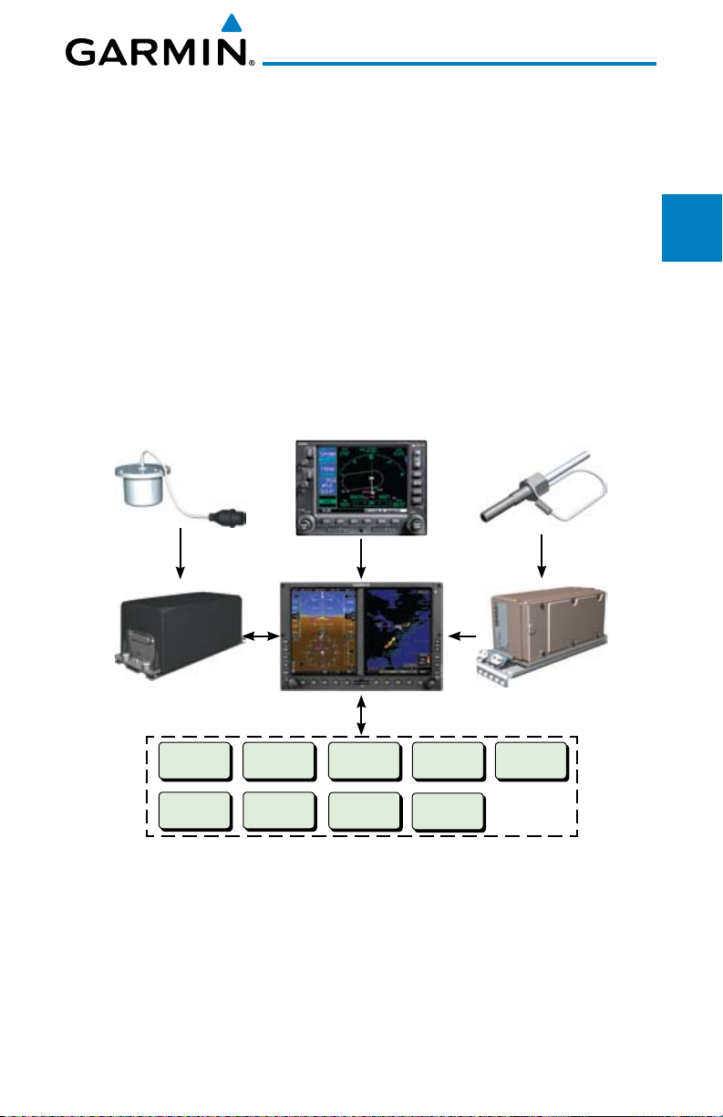
1 SYSTEM OVERVIEW
1.1 System Description
Foreword
This section provides an overview of the G600 Avionics Display System.
The G600 system is an integrated display system that presents primary flight
System
instrumentation, navigation, and a moving map to the pilot through largeformat displays.
In normal operating mode, the Primary Flight Display (PFD) presents
PFD
graphical flight instrumentation (attitude, heading, airspeed, altitude, vertical
speed), replacing the traditional flight instrument cluster. The Multi-Function
Display (MFD) normally displays a full-color moving map with navigation
MFD
information, as well as supplemental data.
GMU 44 Magnetometer
GRS 77 AHRS
Audio Panel
SL 30
GPS Navigator(s)
GDU 620
Optional Interfaces
Autopilot
Flight Director
ADF
GDL 69/69A
GWX 68
Traffic
GAD 43
Temperature Probe
GDC 74 Air Data Computer
GTX330/330D
Avoidance
Features
& Alerts
Symbols
Glossary Appendix A
Sec 1
Sec 2
Sec 3
Hazard
Sec 4
Additional
Sec 5
Annun.
Sec 6
Sec 7
Sec 8
Figure 1-1 G600 System (LRU Configuration)
The system consists of the following Line Replaceable Units (LRUs):
• GDU 620 Primary Flight Display (PFD) and Multi Function Display
(MFD)
• GDC 74A/74B Air Data Computer (ADC)
• GRS 77 Attitude and Heading Reference System (AHRS)
Garmin G600 Pilot’s Guide
1-1190-00601-02 Rev. E
Appendix B
Index
Page 18

• GNS 480, CNX80, GNS 400W series, or GNS 500W series, or a
compatible GPS Navigator
• Temperature Probe (such as the GTP 59)
Foreword
• GMU 44 Magnetometer
• GDL 69/69A Satellite Data Link Receiver (optional)
Sec 1
System
• GSR 56 Satellite Data Link Receiver (optional)
• SL30 NavCom (optional)
PFD
Sec 2
• Autopilot/Flight Director (optional)
• ADF (optional)
• Garmin GTS or GTX traffic awareness systems, or selected 3rd party
MFD
Sec 3
devices (optional)
• Audio Panel (optional)
Sec 4
• GAD 43 Adapter (optional)
Hazard
Avoidance
• Garmin GWX systems or selected 3rd party radar (optional)
1.1.1 Line Replaceable Units (LRU)
Sec 5
Features
Additional
This guide covers the operation of the GDU 620 display as integrated in the
G600 system. The G600 Avionics Display System is an avionics suite designed
to replace the traditional flight instrument cluster. The system combines
Sec 6
Annun.
& Alerts
primary flight instrumentation, navigational information, and a moving map all
displayed on dual color screens. The G600 system is composed of sub-units or
Line Replaceable Units (LRUs). LRUs have a modular design and can be installed
Sec 7
Symbols
directly behind the instrument panel or in a separate avionics bay if desired.
This design greatly eases troubleshooting and maintenance of the G600 system.
A failure or problem can be isolated to a particular LRU, which can be replaced
Sec 8
GlossaryAppendix A
quickly and easily. Each LRU has a particular function, or set of functions, that
contributes to the system’s operation.
Index
Appendix B
1-2
Garmin G600 Pilot’s Guide
190-00601-02 Rev. E
Page 19
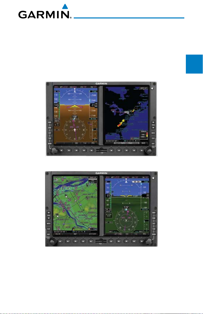
1.1.2 GDU 620
The GDU 620 has dual VGA (640 x 480 pixels) 6.5 inch LCD displays. The
left side of the GDU is a PFD and the right side is the MFD. In some models or
installations, the PFD and MFD and their controls are switched to the other side.
The MFD shows a moving map, flight plan, weather, and other supplemental
data. The PFD shows primary flight information, in place of traditional pitotstatic and gyroscopic systems and also provides an HSI for navigation.
Figure 1-2 GDU 620 PFD and MFD
Foreword
System
Sec 1
Sec 2
PFD
Sec 3
MFD
Avoidance
Hazard
Sec 4
Additional
Features
Sec 5
& Alerts
Annun.
Sec 6
Figure 1-3 GDU 620 PFD and MFD with PFD on Right
Garmin G600 Pilot’s Guide
Symbols
Glossary Appendix A
Index
1-3190-00601-02 Rev. E
Sec 7
Sec 8
Appendix B
Page 20
1.1.3 GDC 74A/74B
The GDC 74A/74B Air Data Computer (ADC) compiles information from
the pitot/static system and an Outside Air Temperature (OAT) sensor. The
Foreword
GDC 74A/74B provides pressure altitude, airspeed, vertical speed, and OAT
information to the G600 system. The GDC 74A/74B communicates with the
GDU 620 and GRS 77 using an ARINC 429 digital interface.
Sec 1
System
PFD
Sec 2
MFD
Sec 3
Figure 1-4 GDC 74A/74B Air Data Computer
1.1.4 GRS 77
Sec 4
Hazard
Avoidance
The GRS 77 is an Attitude and Heading Reference System (AHRS) unit that
provides aircraft attitude information to the G600 display. The unit contains
advanced tilt sensors, accelerometers, and rate sensors. In addition, the GRS 77
Sec 5
Features
interfaces with both the GDC 74A/74B Air Data Computer and the GMU 44
Additional
magnetometer. The GRS 77 also utilizes GPS data forwarded from the GDU 620.
Actual attitude and heading information is sent to the GDU 620 using an ARINC
Sec 6
Annun.
& Alerts
429 digital interface.
Sec 7
Symbols
Sec 8
GlossaryAppendix A
Figure 1-5 GRS 77 AHRS
The IGRF (International Geomagnetic Reference Field) model is contained
in the GRS 77 and is only updated once every five years. The IGRF model is
part of the Navigation Database. At system power-up, the IGRF models in the
GRS 77 and in the Navigation Database are compared, and if the IGRF model in
the GRS 77 is out of date, the user is prompted to update the IGRF model in the
Index
GRS 77. The prompt will appear after the G600 splash screen is acknowledged
Appendix B
on the MFD.
1-4
Garmin G600 Pilot’s Guide
190-00601-02 Rev. E
Page 21
1.1.5 GMU 44
The GMU 44 magnetometer senses the earth’s magnetic field. Data is sent
to the GRS 77 AHRS for processing to determine aircraft magnetic heading.
This unit receives power directly from the GRS 77 and communicates with the
GRS 77 using a RS-485 digital interface.
Figure 1-6 GMU 44 Magnetometer
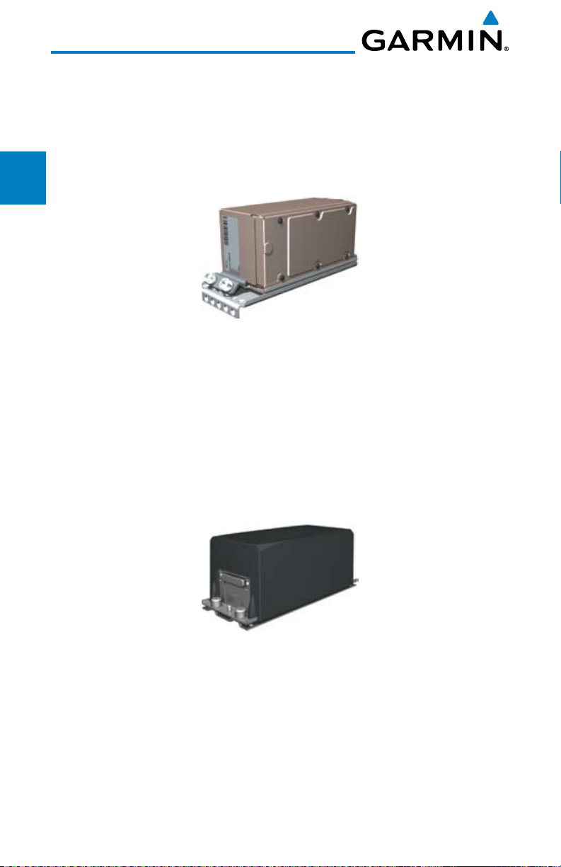
1.1.6 GTX 330/330D (Optional)
Figure 1-7 GTX 330/330D Mode S Transponder
The GTX 330/330D is a solid-state transponder that provides Modes A, C,
and S functions. The transponder provides traffic information to the display
through an ARINC 429 digital interface.
NOTE: GTX 33/33D can also be used to display traffic information on the
GDU 620.
Foreword
System
PFD
MFD
Avoidance
Features
& Alerts
Sec 1
Sec 2
Sec 3
Hazard
Sec 4
Additional
Sec 5
Annun.
Sec 6
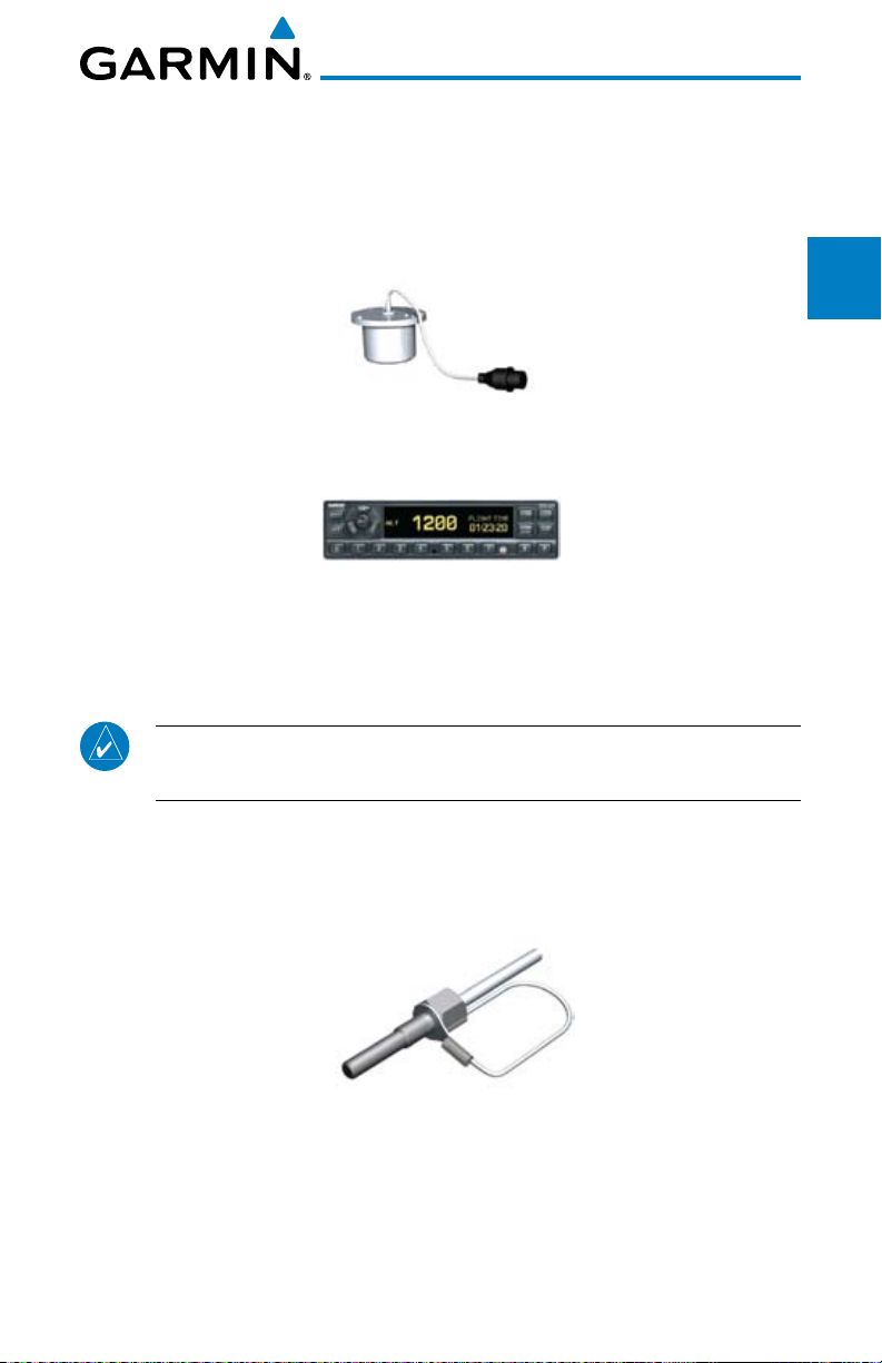
1.1.7 GTP 59
The GTP 59 temperature probe provides Outside Air Temperature (OAT)
data to the GDC 74A/74B.
Figure 1-8 GTP 59 Temperature Probe
1.1.8 GSR 56
The GSR 56 is an Iridium® satellite transceiver that supports voice telephone
calls, aircraft position reporting, and world wide weather products.
Garmin G600 Pilot’s Guide
Symbols
Glossary Appendix A
Index
1-5190-00601-02 Rev. E
Sec 7
Sec 8
Appendix B
Page 22
1.1.9 GDL 69/69A (Optional)
The GDL 69/69A is an XM Satellite Radio Data Link Receiver that receives
broadcast weather data. The GDL 69A is the same as the GDL 69 with the
Foreword
addition of an XM Satellite Radio audio entertainment receiver. Weather data
and control of audio channel and volume is displayed on the MFD, via a HighSpeed Data Bus (HSDB) Ethernet connection. The GDL 69A is also interfaced
Sec 1
System
to an audio panel for distribution of the audio signal. A subscription to the XM
Satellite Radio service is required to enable the GDL 69/69A capability.
PFD
Sec 2
MFD
Sec 3
Sec 4
Hazard
Avoidance
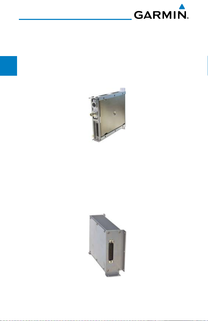
1.1.10 GAD 43
Sec 5
Features
Additional
The GAD 43 is an adapter that converts AHRS digital pitch, roll, heading
and yaw rate data into analog signals used by autopilot systems. The GAD 43
is installed remotely between the AHRS and an existing autopilot. The analog
Sec 6
Annun.
& Alerts
signals from the GAD 43 mimic those of spinning-mass gyros that provide
attitude data to the autopilot and allow the gyro to be replaced by the AHRS
and GAD 43 combination.
Sec 7
Symbols
Figure 1-9 GDL 69/69A XM Satellite Radio Data Link Receiver
Sec 8
GlossaryAppendix A
Index
Appendix B
1-6
Figure 1-10 GAD 43 AHRS Adapter
Garmin G600 Pilot’s Guide
190-00601-02 Rev. E
Page 23
1.1.11 GWX 68 Weather Radar
The Garmin GWX system, or selected 3rd party radar, provides airborne
weather and ground mapped radar data to the MFD.
Figure 1-11 GWX 68 Weather Radar
Foreword
System
Sec 1
Sec 2
PFD
1.1.12 Garmin Navigator Interface
The G600 system requires connection to at least one external Garmin WAAS
GPS navigator, such as the 400W/500W series or GNS 480.
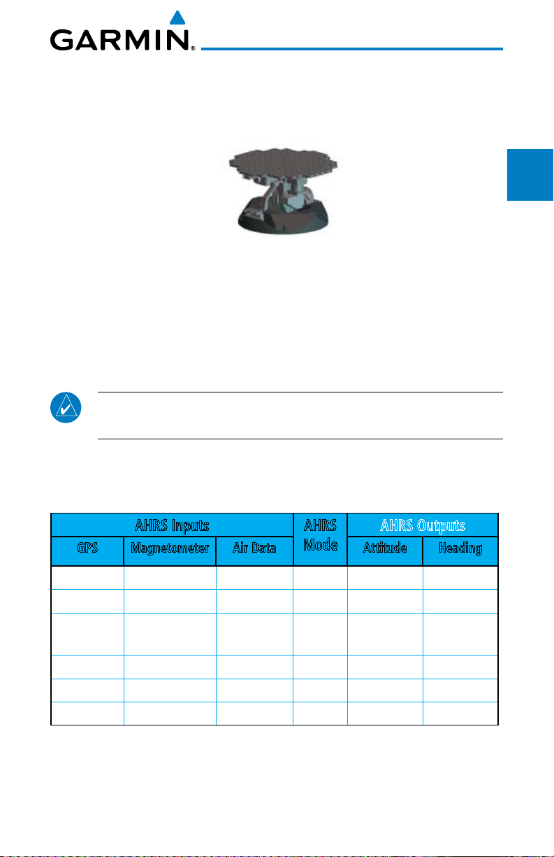
1.1.13 Attitude Heading Reference System (AHRS)
NOTE: Aggressive maneuvering while AHRS is not operating in normal
mode may degrade AHRS accuracy.
Attitude and heading information is displayed on the PFD when the AHRS
receives appropriate combinations of information from the external sensor
inputs.
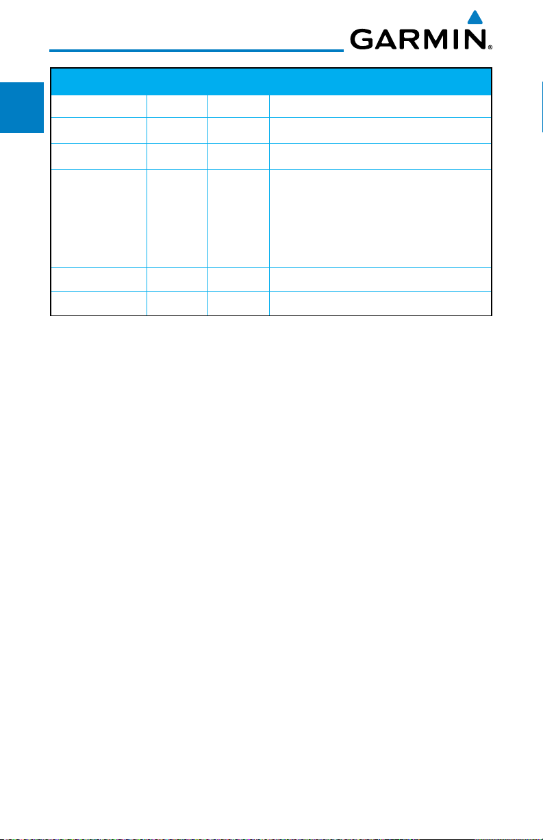
AHRS Inputs AHRS
GPS Magnetometer Air Data Attitude Heading
Mode
Available Available — Normal Available Available
Available Unavailable Available No Mag Available GPS Track
Available Unavailable Unavailable No Air/
No Mag
Unavailable Available Available No GPS Available Available
Unavailable Available Unavailable Fail Unavailable Unavailable
Unavailable Unavailable — Fail Unavailable Unavailable
Table 1-1 AHRS Operation
AHRS Outputs
Available GPS Track
Sec 3
MFD
Avoidance
Hazard
Sec 4
Additional
Features
Sec 5
& Alerts
Annun.
Sec 6
Symbols
Sec 7
Glossary Appendix A
Sec 8
Appendix B
Index
Garmin G600 Pilot’s Guide
1-7190-00601-02 Rev. E
Page 24
Sec 1
Foreword
System
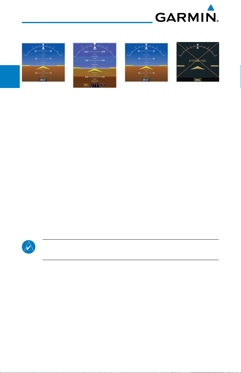
AHRS Normal
Operation
Heading
Invalid
AHRS No-GPS
Mode
Altitude/Heading
Invalid
Figure 1-12 AHRS Operation
Loss of GPS, magnetometer, or air data inputs is communicated to the pilot by
PFD
Sec 2
message advisory alerts (refer to Section 6 for specific AHRS alert information).
Any failure of the internal AHRS inertial sensors results in loss of attitude and
heading information (indicated by red “X” flags over the corresponding flight
MFD
Sec 3
instruments).
A maximum of two GPS inputs are provided to the AHRS. If GPS information
from one of the inputs fails, the AHRS uses the remaining GPS input and an
Sec 4
Hazard
Avoidance
alert message is issued to inform the pilot. If both GPS inputs fail, the AHRS
will continue to provide attitude and heading information to the PFD as long as
magnetometer and airspeed data are available and valid.
Sec 5
Features
Additional
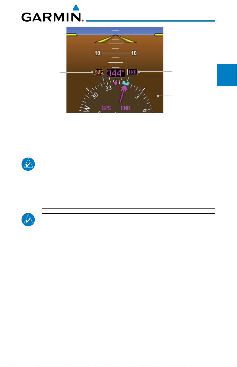
If the magnetometer input fails, the AHRS continues to output valid attitude
information and GPS Track information is used; however, the heading display
on the PFD is flagged as invalid with a red “X,” “TRK” in magenta is annunciated
Sec 6
Annun.
& Alerts
to the right of the Track value, and the Track value color is changed from white
to magenta.
Sec 7
Symbols
NOTE: In this case the magnetic standby compass and GPS ground track
can be used to keep the aircraft on the desired heading.
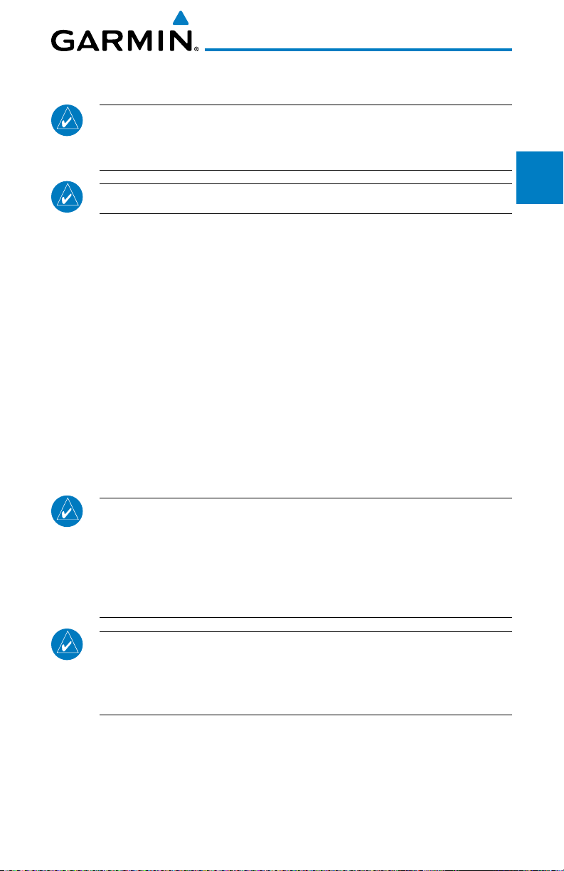
Note that SVT is turned off in “track-based reversionary mode” and must be
Sec 8
manually re-enabled when heading is restored. Also, map orientations change
GlossaryAppendix A
from HDG UP to TRACK UP and must be manually changed back after heading
is restored.
When heading fails the heading bug is not removed and the GDU continues
driving the autopilot heading error output using track in place of heading.
Index
Appendix B
1-8
Garmin G600 Pilot’s Guide
190-00601-02 Rev. E
Page 25
Heading Failed
Track Mode Active
Foreword
System
Sec 1
SVT Is Turned Off
When Heading
Fails
Figure 1-13 Track Mode shown as Active when Heading Info has failed
PFD
MFD
Sec 2
Sec 3
Failure of the air data input has no effect on the AHRS output while AHRS is
receiving valid GPS information. Invalid or unavailable airspeed data in addition
to complete GPS failure results in loss of all attitude and heading information.
NOTE: Fastest AHRS alignment is achieved with the aircraft stationary
and with all AHRS inputs valid (3-D GPS position, magnetometer, and
air data). During initial power up on the ground, no GPS position and/or
magnetic anomalies are common. If the aircraft is taxied prior to AHRS
alignment, alignment may be delayed until after a valid 3-D GPS position
is available.
NOTE: During in-flight alignment of the AHRS, minimize aircraft
maneuvering. The AHRS will align with shallow banking and pitch angles
(less than 20 degrees of roll or 5 degrees of pitch). AHRS alignment may
not be possible during more aggressive maneuvers.
Avoidance
Hazard
Sec 4
Additional
Features
Sec 5
& Alerts
Annun.
Sec 6
Symbols
Sec 7
Glossary Appendix A
Sec 8
Garmin G600 Pilot’s Guide
Appendix B
Index
1-9190-00601-02 Rev. E
Page 26

1.1.14 Secure Digital Cards
The G600 System uses Secure Digital (SD) cards to load and store various types
of data. For basic flight operations, SD cards are required for Terrain, Obstacle,
Foreword
FliteChart, SafeTaxi, and ChartView database storage as well as Jeppesen aviation
and ChartView database updates. The Aviation Database update card is generally
inserted in the upper SD card slot for database updates and then removed. Other
Sec 1
System
database cards are normally located in the lower SD card slot. ChartView is an
optional feature that requires enablement by a Garmin dealer.
PFD
Sec 2
Sec 3
Sec 4
Hazard
Sec 5
Additional
NOTE: Ensure the GDU 620 is powered off before inserting or removing
an SD card.
MFD
NOTE: Refer to Appendix A for instructions on updating the aviation
database.
Inserting an SD Card
Avoidance
1) Insert the SD card in the SD card slot (the front of the card should be flush with
the face of the display bezel).
2) To eject the card, gently press on the SD card to release the spring latch.
Features
Sec 6
Annun.
Sec 7
Sec 8
Appendix B
& Alerts
Symbols
GlossaryAppendix A
Index
1-10
Garmin G600 Pilot’s Guide
190-00601-02 Rev. E
Page 27
1.2 System Power Up
NOTE: See the Aircraft Flight Manual (AFM) for specific procedures
concerning avionics power application and emergency power supply
operation.
NOTE: Refer to Section 6 for system-specific annunciations and alerts.
The G600 System is integrated with the aircraft electrical system and receives
power directly from electrical busses. The GDU 620 and supporting sub-systems
include both power-on and continuous built-in test features that exercise the
processor, memory, external inputs, and outputs to ensure safe operation.
During system initialization, test annunciations are displayed. All system
annunciations should disappear typically within the first 30 seconds after powerup. Upon power-up, bezel key backlights also become momentarily illuminated
on the GDU 620 display bezel.
Foreword
System
Sec 1
Sec 2
PFD
Sec 3
MFD
Avoidance
Hazard
Sec 4
On the PFD, the AHRS begins to initialize and “AHRS ALIGN: Keep Wings
Level” is displayed. The AHRS should display valid attitude and heading fields
typically within the first minute after power-up. The AHRS can align itself both
while taxiing and during level flight.
NOTE: Fastest AHRS alignment is achieved with the aircraft stationary
and with all AHRS inputs valid (3-D GPS position, magnetometer, and
air data). During initial power up on the ground, no GPS position and/or
magnetic anomalies are common. If the aircraft is taxied prior to AHRS
alignment, alignment may be delayed until after a valid 3-D GPS position
is available.
NOTE: During in-flight alignment of the AHRS, minimize aircraft
maneuvering. The AHRS will align with shallow banking and pitch angles
(less than 20 degrees of roll or 5 degrees of pitch). AHRS alignment may
not be possible during more aggressive maneuvers.
Additional
Features
Sec 5
& Alerts
Annun.
Sec 6
Symbols
Sec 7
Glossary Appendix A
Sec 8
Appendix B
Index
Garmin G600 Pilot’s Guide
1-11190-00601-02 Rev. E
Page 28
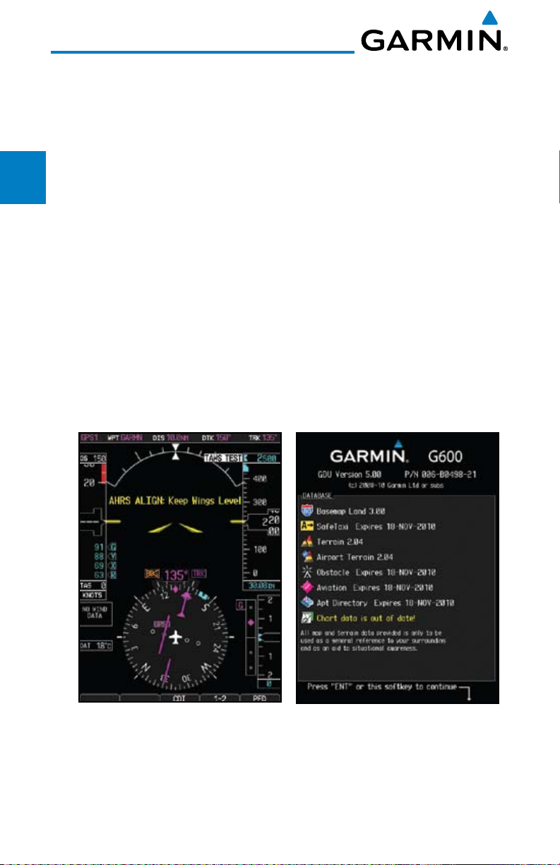
When the MFD powers up, the splash screen displays the following
information:
• Softwareversion and part number
Foreword
• Copyright
• Landdatabasenameandversion
Sec 1
System
• Obstacledatabase name and version
• Terrain database name and version
PFD
Sec 2
• Aviationdatabasename,version,andeffectivedates
• AirportDirectoryexpirationdate
Current database information includes valid operating dates, cycle number,
MFD
Sec 3
and database type. When this information has been reviewed for currency (to
ensure that no databases have expired), the pilot is prompted to continue.
Sec 4
Databases are displayed in white if they are determined to be current.
Hazard
Avoidance
Databases are displayed in yellow if they have expired, are not yet effective, or if
the current date/time is not yet available from the GPS.
Sec 5
Features
Additional
Sec 6
Annun.
& Alerts
Sec 7
Symbols
Sec 8
GlossaryAppendix A
Figure 1-14 System Startup Pages
Index
Appendix B
1-12
Garmin G600 Pilot’s Guide
190-00601-02 Rev. E
Page 29

1.3 International Geomagnetic Reference Field
Foreword
The IGRF (International Geomagnetic Reference Field) model is contained in
the GRS 77 and is only updated once every five years. The IGRF model is part of
the Navigation Database. At system power-up, the IGRF models in the GRS 77
and in the Navigation Database are compared, and if the IGRF model in the GRS
77 is out of date, the user is prompted to update the IGRF model in the GRS 77.
The following prompt will appear after the G600 splash screen is acknowledged
on the MFD.
GRS MV DB UPDATE AVAILABLE.UPDATE FROM yyyy TO yyyy
(e.g. 2005 to 2010)
Pressing the ENT key (or right-most soft key) acknowledges this information
and displays the Navigation Map Page. When the interfaced GPS unit has
acquired a sufficient number of satellites to determine a position, the aircraft’s
current position is shown on the Navigation Map Page.
System
PFD
MFD
Avoidance
Features
& Alerts
Sec 1
Sec 2
Sec 3
Hazard
Sec 4
Additional
Sec 5
Annun.
Sec 6
Garmin G600 Pilot’s Guide
1-13190-00601-02 Rev. E
Symbols
Sec 7
Glossary Appendix A
Sec 8
Appendix B
Index
Page 30

1.4 System Operation
Foreword
1.4.1 Pilot Controls
Sec 1
System
and minimize workload and the time required to access functionality. Controls
are located on the PFD and MFD bezels and are comprised of a PFD knob, MFD
PFD
Sec 2
dual concentric knobs, bezel keys, and soft keys.
1.4.1.1 PFD Knob
MFD
Sec 3
bezel keys, such as, Heading (HDG), Course (CRS), Altitude (ALT), Vertical
Speed (V/S), and Barometric Setting (BARO). The values are shown in a window
to the left of the HSI. Pressing the PFD knob reverts to the default value of the
Sec 4
Hazard
selected mode.
Avoidance
Sec 5
Features
Additional
NOTE: Refer to Section 6 for detailed descriptions of all alerts and
annunciations.
The GDU 620 controls have been designed to simplify operation of the system
Turning the PFD knob adjusts the values for the mode selected by the PFD
Heading
Mode
Course
Mode
Altitude
Mode
Vertical Speed
Mode
Barometer
Mode
Sec 6
Annun.
& Alerts
Figure 1-15 Selection Modes Adjusted with the PFD Knob
Sec 7
Symbols
NOTE: After 10 seconds of inactivity in another mode, the PFD knob
selected mode will revert to Heading mode.
1. Press the desired PFD mode selection key (HDG, CRS, A LT, V/S, or BARO). A
Sec 8
GlossaryAppendix A
window will be displayed near the upper right corner of the HSI showing the
current value for that mode.
2. Turn the PFD knob to select the desired value.
Index
Appendix B
1-14
Garmin G600 Pilot’s Guide
190-00601-02 Rev. E
Page 31

1.4.1.2 PFD Bezel Keys
Heading (HDG)
Selects Heading Select mode. Pressing the PFD knob in Heading mode will
center the Heading Bug on the current Heading. This is the default mode for
the PFD knob. Set the heading on the HSI by turning the PFD knob after
pressing the HDG key.
Course (CRS)
Selects Course Select mode. Pressing the PFD knob in Course mode will
center the CDI for a VOR or OBS mode course.
Altimeter (ALT)
Selects Altitude Select mode. Pressing the PFD knob in Altitude Select mode
will enter the current altitude in the Altitude Select window. Set the Altitude
Bug by turning the PFD knob after pressing the ALT key.
Altitude Select Window
Altitude Bug
Current Altitude
Foreword
System
Sec 1
Sec 2
PFD
Sec 3
MFD
Avoidance
Hazard
Sec 4
Additional
Features
Sec 5
& Alerts
Annun.
Sec 6
Barometric Setting
Figure 1-16 Pressing PFD Knob Sets Altitude Select to Current Altitude
Garmin G600 Pilot’s Guide
1-15190-00601-02 Rev. E
Symbols
Sec 7
Glossary Appendix A
Sec 8
Appendix B
Index
Page 32

Vertical Speed (V/S)
Selects Vertical Speed (V/S) mode. Pressing the PFD knob in V/S mode will
synchronize the bug to the current vertical speed.
Foreword
Sec 1
System
Vertical Speed Bug
PFD
Sec 2
MFD
Sec 3
Sec 4
Hazard
Figure 1-17 Pressing V/S Knob Sets Vertical Speed Bug to Current Vertical Speed
Avoidance
Barometer (BARO)
Sec 5
Selects Barometric Setting Select mode. Pressing the PFD knob in Baro mode
Features
Additional
will enter the standard pressure (29.92 in/1013 mb) value.
1.4.1.3 MFD Knobs
Sec 6
The MFD knobs are for navigating and selecting information on the MFD
Annun.
& Alerts
pages. More details are provided in the MFD section.
Small (Inner) MFD Knob
Sec 7
Symbols
Selects a specific page within a page group. Pressing the small MFD knob
turns the selection cursor ON and OFF. When the cursor is ON, data may be
entered in the applicable window by turning the small and large MFD knobs.
Sec 8
In this case, the large MFD knob moves the cursor on the page and the small
GlossaryAppendix A
MFD knob selects individual characters or values for the highlighted cursor
location.
Current Vertical Speed
Vertical Speed Bug Setting
Large (Outer) MFD Knob
Selects the MFD page group. When the cursor is ON, the large MFD knob
moves the cursor to highlight available fields.
Index
Appendix B
1-16
Garmin G600 Pilot’s Guide
190-00601-02 Rev. E
Page 33

1.4.1.4 MFD Bezel Keys
Range (RNG)
Pressing the Range arrow keys changes the range on the Map pages. The Up
arrow zooms out. The Down arrow zooms in. The keys also aid in scrolling
up and down text pages.
Menu
Displays a context-sensitive list of options. This list allows the user to access
additional features or make setting changes that relate to particular pages.
Enter (ENT)
Validates or confirms a menu selection or data entry.
Clear (CLR)
Erases information, cancels entries, or removes page menus. Pressing and
holding the CLR key displays the Navigation Map 1 page.
1.4.2 Using the Soft Key Controls
Foreword
System
Sec 1
Sec 2
PFD
Sec 3
MFD
Avoidance
Hazard
Sec 4
Additional
Features
Sec 5
The soft keys are located along the bottoms of the displays. The soft key
labels shown depend on the soft key level or page being displayed. The bezel
keys below the soft keys can be used to select the appropriate soft key.
MFD functions indicated by the soft key labels vary depending on the page
selected and are located at the bottom of the MFD display. Press the soft key
located directly below the soft key label. To select the function indicated on the
soft key label, press the soft key directly below the label.
Selected Soft Key
Figure 1-18 MFD Soft Key Layout
Garmin G600 Pilot’s Guide
Unselected Soft Keys
Soft Key Labels
Soft Keys
1-17190-00601-02 Rev. E
& Alerts
Annun.
Sec 6
Symbols
Sec 7
Glossary Appendix A
Sec 8
Appendix B
Index
Page 34

1.4.3 Using the Page Menus
The GDU 620 has a dedicated MENU key that when pressed displays a
context-sensitive list of options for functions in the MFD. This options list allows
Foreword
the user to access additional features or make settings changes which specifically
relate to the currently displayed window/page. There is no all-encompassing
menu. Some menus provide access to additional submenus that are used to view,
Sec 1
System
edit, select, and review options. Menus display “No Options” when there are no
options for the window/page selected. Soft key presses do not display menus or
submenus.
PFD
Sec 2
Navigating within a Menu
1) Press the MENU key to display the menu.
MFD
Sec 3
2) Turn the small or large MFD knob to scroll through a list of available options (a
scroll bar always appears to the right of the window/box when the option list
Sec 4
Hazard
Sec 5
Additional
is longer than the window/box).
Avoidance
3) Press the ENT key to select the desired option.
4) Press the CLR key or MFD knob to remove the menu and cancel the
operation.
Features
No Options Options for MAP Window
Sec 6
Annun.
Sec 7
Sec 8
Appendix B
& Alerts
Symbols
GlossaryAppendix A
Index
1-18
Figure 1-19 Page Menu Examples
Garmin G600 Pilot’s Guide
190-00601-02 Rev. E
Page 35

1.4.4 System Settings
G600 system settings are managed from the Aux Mode System Setup
Page. The following settings can be changed:
Foreword
• DisplayBrightness (Mode and Level)
• AirspeedReferences (Glide, Vr, Vx, and Vy)
• PFDOptions (Wind Vector)
• DualUnitSynchronization (CDI and Baro) - Dual installations only
• Date/Time(Date, Time, Time Format, and Time Offset)
• MFDDisplayUnits (Distance/Speed and Altitude/Vertical Speed)
•System Display Units (Navigation Angle Reference, Pressure Units, and
Temperature Units)
System
Sec 1
Sec 2
PFD
Sec 3
MFD
Avoidance
Hazard
Sec 4
Additional
Features
Sec 5
& Alerts
Annun.
Sec 6
Symbols
Sec 7
Figure 1-20 System Setup Page
Garmin G600 Pilot’s Guide
1-19190-00601-02 Rev. E
Glossary Appendix A
Sec 8
Appendix B
Index
Page 36

System Settings Values
1) From the first AUX page, press the small MFD knob and turn the large MFD
knob to highlight the desired value.
Foreword
2) Turn the small MFD knob to select “ON” or “OFF.”
3) Press ENTER to save the setting.
Sec 1
System
More detail on changing settings is in the Section 3 - MFD Aux pages System
Settings section.
PFD
Sec 2
Category Settings Affected Quantities Exceptions
Display
Brightness
MFD
Sec 3
Airspeeds Glide
Sec 4
Hazard
Avoidance
Synchronization
Sec 5
Features
Additional
PFD Options
Level
Mode
V
R
V
X
V
Y
CDI - On/Off
BARO - On/Off
Style 1 - Style 4
Brightness levels on the PFD
and MFD
Reference markers on PFD
airspeed tape
Crossfill Nav information to
GDU 620
(Wind Vector)
Date/Time Date
Sec 6
Annun.
& Alerts
Sec 7
Symbols
Distance and
Speed
Sec 8
GlossaryAppendix A
Index
Appendix B
1-20
Time
Time Format
Time Offset
Metric
Nautical
Crosstrack error (HSI)
Bearing distances
(information windows)
Distance (information
window)
Flight plan distances
Map ranges
DIS, GS, TAS, XTK fields
(Navigation Status Box)
All distances on MFD
All speeds on MFD
Garmin G600 Pilot’s Guide
Airspeed Indicator
True Airspeed
(PFD)
Wind speed
vector
Map range (Traffic
Page, Terrain
Proximity Page)
CDI scaling
190-00601-02 Rev. E
Page 37

Category Settings Affected Quantities Exceptions
Altitude and
Vertical Speed
Feet
Meters
All elevations on MFD Altimeter
Vertical Speed
Indicator
Navigation
Angle
Magnetic (North)
True (North)
Heading
Course
Bearing
Track
Desired Track
Foreword
System
Sec 1
Sec 2
PFD
Barometric
Setting
Inches (in)
Hectopascals
Barometric pressure on PFD
(hpa)
Temperature Celsius
All temperatures on PFD
Fahrenheit
Table 1-2 Display Units Settings (System Setup Page)
More detail on changing settings is in the Section 3 - MFD Aux pages System
Settings section.
Sec 3
MFD
Avoidance
Hazard
Sec 4
Additional
Features
Sec 5
& Alerts
Annun.
Sec 6
Symbols
Sec 7
Glossary Appendix A
Sec 8
Garmin G600 Pilot’s Guide
Appendix B
Index
1-21190-00601-02 Rev. E
Page 38

1.4.5 Display Backlighting
The backlighting of the PFD and MFD displays and bezel keys can be
adjusted automatically or manually. The default setting (automatic backlighting
Foreword
adjustment) uses the photocell located at the top right corner of the bezel to
automatically adjust for ambient lighting conditions. Photocell calibration
curves are configured by the installer to optimize display appearance through
Sec 1
System
a broad range of cockpit lighting conditions. Manual backlighting adjustment
can be accomplished using the existing instrument panel dimmer bus or the
following procedures.
PFD
Sec 2
Backlighting Adjustment
1) From the first AUX page, press the small MFD knob to highlight the “DISPLAY
MFD
Sec 3
Sec 4
Hazard
Sec 5
Additional
BRIGHTNESS” “MODE” box.
2) Turn the small MFD knob to select the desired brightness Level and then press
ENTER.
Avoidance
Manual Adjustment 0.1% to 50%
or Auto (1.7%)
Features
Auto or Manual
Sec 6
Annun.
& Alerts
3) Turn the large MFD knob to highlight the MODE field. Turn the small MFD
knob to select “AUTO” or “MANUAL.”
4) Press ENT.
Sec 7
Symbols
Sec 8
GlossaryAppendix A
Index
Appendix B
Figure 1-21 Display Brightness Adjustment
1-22
Garmin G600 Pilot’s Guide
190-00601-02 Rev. E
Page 39

2 PRIMARY FLIGHT DISPLAY (PFD)
Functions on the PFD are accessed by using the bezel keys on the side of the
PFD and the soft keys below the PFD.
Horizon
Line
Air Speed Tape
Slip/Skid
Indicator
Roll Scale
Zero
Roll
Pointer
Nav Status Bar
Altitude Tape
Foreword
System
Sec 1
Sec 2
PFD
PFD Knob Mode Indicator
Wind Vectors
Heading Bug Select
Course Select
Altitude Bug Select
Vertical Speed Bug Select
Barometric Setting Select
Outside Air Temperature
PFD Knob
Figure 2-1 PFD Description (Ground Pointer Mode)
Current FPL
Leg Wpt
Current Nav
Source
Figure 2-2 PFD Nav Status Bar Description
Soft Key Labels
Distance from Your
Present Position to
Current FPL Leg Wpt
Soft Keys
Current
Barometric
Pressure Setting
Vertical
Speed Tape
Horizontal
Situation
Indicator
SD Card Slots
Desired Track
Current Track
Sec 3
MFD
Avoidance
Hazard
Sec 4
Additional
Features
Sec 5
& Alerts
Annun.
Sec 6
Symbols
Sec 7
Glossary Appendix A
Sec 8
NOTE: When navigating to a waypoint very far away the DTK, CRS, and
TRK values displayed on the GDU 620 may differ from those displayed
on the navigator, however the CDI is correct and is the primary means
of navigation. This is because the GDU 620 applies magnetic variation
corrections for the current aircraft location, but some navigators apply
magnetic variation correction for the waypoint location.
Garmin G600 Pilot’s Guide
2-1190-00601-02 Rev. E
Appendix B
Index
Page 40

2.1 PFD Soft Keys
Foreword
Sec 1
System
AP TEST
CDI
GPS
VOR/ILS
1-2
Source 1
Source 2
PFD
BRG 1
NAV 1
GPS 1
ADF
PFD
Sec 2
SYN VIS
SYN TERR
HRZN HDG
MFD
Sec 3
APTSIGNS
BRG 2
Sec 4
Hazard
Avoidance
Sec 5
Features
Additional
Figure 2-3 PFD Soft Key Diagram
The soft keys are located along the bottoms of the displays below the soft
NAV 2
GPS 2
ADF
key labels. The soft key labels shown depend on the soft key level or page being
displayed. The soft keys can be used to select the appropriate soft key function.
Sec 6
Annun.
& Alerts
Selected Soft Key Unselected Soft Key
Sec 7
Symbols
Sec 8
GlossaryAppendix A
Index
Appendix B
2-2
Unselected Soft Key
Soft Key Not Available
For Selection
Figure 2-4 PFD Soft Key Layout
Garmin G600 Pilot’s Guide
Soft Key Labels
Soft Keys
Soft Key Labels
190-00601-02 Rev. E
Page 41

When a soft key is selected, its color changes to black text on gray background
and remains this way until it is turned off, at which time it reverts to white text
on black background. When a soft key function is disabled, the soft key label
is subdued (dimmed). Soft keys revert to the previous level after 45 seconds of
inactivity.
NOTE: If a soft key is pressed and held for longer than 1 second, it is
ignored.
AP Test
The AP TEST soft key is available if the GAD 43 is installed. The AP TEST
soft key disengages the autopilot as part of the GAD 43 test.
CDI
Foreword
System
Sec 1
Sec 2
PFD
Sec 3
MFD
The CDI soft key toggles between the selection of GPS or VOR/LOC as the
active navigation source. In a single GDU 620 system, the GDU CDI soft
key will change the source in the connected navigator and making a source
change in the navigator will be reflected in the GDU 620. In a dual GDU 620
system, the CDI keys in the navigator will be disabled.
1-2
The 1-2 soft key toggles between the available receivers for selected navigation
source (i.e. GPS1 and GPS2 or VOR/LOC1 and VOR/LOC2). This soft key
will only be present if the system is configured for a second GPS or VOR/
LOC.
PFD
Pressing the PFD soft key displays the BRG1, BRG2, and BACK soft keys.
The BRG2 soft key will only be present if the system is configured for a
second GPS or VOR/LOC receiver.
BRG1
The BRG1 soft key cycles through the available bearing 1 indicator modes
(NAV1, GPS1, ADF, or None).
BRG2
The BRG2 soft key cycles through the available bearing 2 indicator modes
(NAV2, GPS2, ADF, or None). This soft key will only be present if the system
is configured for a second GPS or VOR/LOC.
Avoidance
Hazard
Sec 4
Additional
Features
Sec 5
& Alerts
Annun.
Sec 6
Symbols
Sec 7
Glossary Appendix A
Sec 8
Appendix B
Index
Garmin G600 Pilot’s Guide
2-3190-00601-02 Rev. E
Page 42

Foreword
Sec 1
System
PFD
Sec 2
MFD
Sec 3
Sec 4
Hazard
Avoidance
Sec 5
Features
Additional
SYN VIS
The SYN VIS soft key is available if Synthetic Vision Technology™ is installed.
It enables Synthetic Vision and displays the associated soft keys.
SYN TERR
The SYN TERR soft key is available if Synthetic Vision Technology™ is
installed and enables synthetic terrain depiction.
HRZN HDG
The HRZN HDG soft key is available if Synthetic Vision Technology™ is
installed. Pressing this key enables horizon heading marks and digits.
APTSIGNS
The APTSIGNS soft key is available if Synthetic Vision Technology™ is
installed and enables airport sign posts.
BACK
The BACK soft key returns to the pages default soft key options.
Sec 6
Annun.
Sec 7
Sec 8
Appendix B
& Alerts
Symbols
GlossaryAppendix A
Index
2-4
Garmin G600 Pilot’s Guide
190-00601-02 Rev. E
Page 43

2.2 Airspeed Indicator
The Airspeed Indicator displays airspeed on a rolling number gauge using a
moving tape. The numeric labels and major tick marks on the moving tape are
marked at intervals of 10 units, while minor tick marks on the moving tape are
indicated at intervals of five units. Speed indication starts at 20 knots, regardless
of the displayed units.
NOTE: Airspeed units (KTS, MPH, KPH) are configured to match the approved
units for the installation.
The Airspeed Indicator provides Indicated Airspeed, True Airspeed, and
Ground Speed. The Airspeed Trend Indicator shows what the airspeed will be
in six seconds, if the current acceleration is maintained. The actual airspeed is
displayed inside the black pointer.
The Airspeed Trend Vector is a vertical, pink/magenta line, extending up or
down on the airspeed scale, shown to the right of the color-coded speed range
strip. The end of the trend vector corresponds to the predicted airspeed in six
seconds if the current acceleration is maintained. If the trend vector crosses into
the overspeed range, the text of the actual airspeed readout changes to yellow.
The trend vector is absent if the speed remains constant or if any data needed to
calculate airspeed is not available due to a system failure.
Foreword
System
Sec 1
Sec 2
PFD
Sec 3
MFD
Avoidance
Hazard
Sec 4
Additional
Features
Sec 5
& Alerts
Annun.
Sec 6
Ground Speed
Caution Range (yellow)
Airspeed Trend Indicator (pink/magenta line)
Glide Speed Reference Marker
Vr Reference Marker
Vx Reference Marker
Landing Gear Extension Speed
Vy Reference Marker
Normal Operating Range (Green)
Flaps Operating Range (White)
True Airspeed
Airspeed Units
Figure 2-5 Airspeed Tape
Garmin G600 Pilot’s Guide
Symbols
Glossary Appendix A
Index
2-5190-00601-02 Rev. E
Sec 7
Sec 8
Appendix B
Page 44

Overspeed Range (Barber Pole)
Foreword
Sec 1
System
Overspeed Indication for
Current Airspeed
Caution Operating Range
Figure 2-6 Overspeed Indication
PFD
Sec 2
2.2.1 Markings
A color-coded (white, green, yellow, and red/white “barber pole”) speed
range strip is located on the moving tape. The colors are configured to match
MFD
Sec 3
the approved markings for the installation. See the AFM/POH.
Sec 4
Hazard
Avoidance
Sec 5
Features
Additional
Sec 6
Annun.
& Alerts
NOTE: The actual colors and patterns of the airspeed tape may vary by
installation. See your AFM/POH for more details.
M
/ V
mo
/ V
V
NE
NO
V
FE
V
S1
mo
Sec 7
Symbols
Sec 8
GlossaryAppendix A
Index
Appendix B
2-6
V
SO
Figure 2-7 Typical Airspeed Tape Markings
Garmin G600 Pilot’s Guide
190-00601-02 Rev. E
Page 45

White Triangle
V
YSE
V
LE
V
MCA
Figure 2-8 Additional Reference Markings
2.2.2 Reference Speeds
V-speeds (Glide, Vr, VX, and VY) default values are set during the installation
process, but can be changed and turned on/off from the System Setup page
on the first page of the Aux page group. When active (on), the V-speeds are
displayed at their respective locations to the right of the airspeed scale. The
values you set are retained when the unit power is cycled.
Glide Reference Marker
Vr Reference Marker
Vx Reference Marker
Foreword
System
Sec 1
Sec 2
PFD
Sec 3
MFD
Avoidance
Hazard
Sec 4
Additional
Features
Sec 5
& Alerts
Annun.
Sec 6
Vy Reference Marker
Figure 2-9 Reference Speeds
Garmin G600 Pilot’s Guide
Symbols
Glossary Appendix A
Index
2-7190-00601-02 Rev. E
Sec 7
Sec 8
Appendix B
Page 46

2.3 Attitude Indicator
Attitude information is displayed over a virtual blue sky and brown ground
Foreword
with a white horizon line. The Attitude Indicator displays pitch, roll, and slip/
skid information.
Roll Pointer
1
Roll Scale
2
Aircraft Symbol
3
7
Horizon Line
4
Land Representation
5
8
Pitch Scale
6
6
Slip/Skid Indicator
7
Sky Representation
8
Roll Scale Zero
9
5
Sec 4
Sec 1
System
PFD
Sec 2
MFD
Sec 3
Hazard
Avoidance
9
1
2
3
4
Figure 2-10 Attitude Indicator
Sec 5
The horizon line is part of the pitch scale. Above and below the horizon line,
Features
Additional
major pitch marks and numeric labels are shown for every 10º, up to 80º. Minor
pitch marks are shown for intervening 5º increments, up to 25º below and 45º
above the horizon line. Between 20º below to 20º above the horizon line, minor
Sec 6
Annun.
& Alerts
pitch marks occur every 2.5º.
Angle of bank is indicated by the position of the pointer on the roll scale.
Sec 7
Major tick marks are 30º and 60º and minor tick marks are 10º, 20º, and 45º
Symbols
are shown to the left and right of the zero.
The Slip/Skid Indicator is the bar beneath the roll pointer. The indicator
Sec 8
moves with the roll pointer and moves laterally away from the pointer to
GlossaryAppendix A
indicate lateral acceleration. Slip/skid is indicated by the location of the bar
relative to the pointer. One bar displacement (as shown below) is equal to one
ball displacement on a traditional Slip/Skid Indicator.
Index
Appendix B
2-8
Garmin G600 Pilot’s Guide
190-00601-02 Rev. E
Page 47

Roll Pointer
Roll Scale Zero
Slip/Skid Indicator
Figure 2-11 Slip/Skid Indication
The standby mechanical Attitude Indicator in your aircraft is either a Ground
Pointer or a Roll Pointer configuration. The GDU 620 Attitude Indicator has
been configured in either a Ground Pointer or a Roll Pointer configuration to
match the configuration of your aircraft’s standby Attitude Indicator. Ground/
Sky Pointer mode is configured during installation and can not be changed by
the pilot.
In an aircraft with an Attitude Indicator that has a Ground Pointer, the pointer
above the Roll Scale shifts with the roll or bank angle of the aircraft to keep the
Roll Scale Zero Pointer pointing towards the ground.
Foreword
System
Sec 1
Sec 2
PFD
Sec 3
MFD
Avoidance
Hazard
Sec 4
Additional
Features
Sec 5
Roll Pointer
Roll Scale Zero Pointer
Roll Scale
Figure 2-12 Attitude Indicator with a Ground Pointer configuration in a left turn
In an aircraft with an Attitude Indicator that has a Sky Pointer, the pointer
below the roll scale shifts with the roll or bank angle of the aircraft to keep the
Roll Pointer pointing towards the sky.
Garmin G600 Pilot’s Guide
2-9190-00601-02 Rev. E
& Alerts
Annun.
Sec 6
Symbols
Sec 7
Glossary Appendix A
Sec 8
Appendix B
Index
Page 48

Roll Scale Zero Pointer
Roll Pointer
Foreword
Sec 1
System
Roll Scale
Figure 2-13 Attitude Indicator with a Sky Pointer configuration in a left turn
2.3.1 Extreme Attitude
PFD
Sec 2
Extreme attitude is defined as a roll greater than 65º left or right, 30º pitch up,
or 20º pitch down. Red chevrons are displayed at greater than 50º pitch up and
30º pitch down. The PFD will “declutter” when the aircraft enters an extreme
MFD
Sec 3
attitude. Only the primary functions will be displayed in these situations.
The following information is removed from the PFD (and corresponding soft
keys are disabled) when the aircraft is in an unusual attitude:
Sec 4
Hazard
• PFDKnobModeAnnunciations
Avoidance
• Ground Speed, True Airspeed, and Airspeed Units
Sec 5
• Selected Altitude, Barometer Settings, and Selected Vertical Speed
Features
Additional
• VerticalCourseDeviationIndicator
• TrafcandTerrain Annunciations
Sec 6
• FlightDirectorCommandBars
Annun.
& Alerts
Sec 7
Symbols
Sec 8
GlossaryAppendix A
Index
Appendix B
2-10
Figure 2-14 Extreme Pitch Indication
Garmin G600 Pilot’s Guide
190-00601-02 Rev. E
Page 49

Figure 2-15 Extreme Pitch Indication Figure 2-16 Extreme Pitch Indication
Nose Down Nose Up
Foreword
System
Sec 1
Sec 2
PFD
Sec 3
MFD
Avoidance
Hazard
Sec 4
Additional
Features
Sec 5
& Alerts
Annun.
Sec 6
Figure 2-17 Extreme Roll Indication with Display Declutter
Garmin G600 Pilot’s Guide
2-11190-00601-02 Rev. E
Symbols
Sec 7
Glossary Appendix A
Sec 8
Appendix B
Index
Page 50

2.4 Altimeter
The altimeter displays the current altitude, altitude trend, altitude bug setting,
altitude bug, and the current BARO setting.
Foreword
The Altitude Trend Vector is a vertical, magenta line, extending up or down
on the left side of the Altitude scale. The end of the trend vector corresponds to
Sec 1
System
the predicted altitude in six seconds if the current vertical speed is maintained.
The Altitude Bug is displayed at the selected Altitude Bug setting. A portion
of the Altitude Bug will be displayed at the top or the bottom of the altitude tape
PFD
Sec 2
if the selected Altitude Bug is off of the tape.
2.4.1 Setting the Altitude Bug and Alerter
MFD
Sec 3
1) Press the ALT key to activate Altitude mode.
2) Turn the PFD knob to move the Altitude Bug to a desired altitude.
OR
Sec 4
Hazard
Avoidance
3) Press the center of the PFD knob to set the selected altitude to the current
altitude.
Sec 5
Features
Additional
Sec 6
Annun.
& Alerts
Selected
Altitude
Bug
Selected
Altitude
in the
Altitude
Alerter
window
Sec 7
Symbols
Sec 8
GlossaryAppendix A
Index
Appendix B
2-12
Altitude
Trend
Indicator
Figure 2-18 Altimeter
Garmin G600 Pilot’s Guide
Current
Altitude
Brown Band With
Stripes (RA Only)
Barometric
Setting
190-00601-02 Rev. E
Page 51

The ground awareness band will be visible when the aircraft is within 250ft
of the ground.
Selected Altitude
Selected Altitude Bug
in the Altitude
Alerter window
Current Altitude
Foreword
System
Sec 1
Sec 2
PFD
Ground Elevation
Ground Band With White
Stripes Indicates Ground
Within 250 feet
Barometric
Setting
Figure 2-19 Ground Awareness Band Showing Ground Is Within 250 Feet
Sec 3
MFD
Avoidance
Hazard
Sec 4
Additional
Features
Sec 5
& Alerts
Annun.
Sec 6
Symbols
Sec 7
Glossary Appendix A
Sec 8
Garmin G600 Pilot’s Guide
Appendix B
Index
2-13190-00601-02 Rev. E
Page 52

2.4.2 Altitude Alerting
The Altitude Alerting function provides the pilot with visual and aural
alerts (if interfaced to an audio panel) when approaching the Selected Altitude.
Foreword
Whenever the Selected Altitude is changed, the Altitude Alerter is reset.
Sec 1
System
PFD
Sec 2
MFD
Sec 3
Sec 4
Hazard
Avoidance
Sec 5
Features
Additional
Sec 6
Annun.
& Alerts
Sec 7
Symbols
NOTE:
The Altitude Alerter function may be disabled in some installations.
When the Altitude Alerter is disabled, pressing the A LT key will result in
an "ALT KEY INOP" message.
The following occur when approaching the Selected Altitude:
• Upon passing through 1000 feet of the Selected Altitude, the Selected
Altitude (shown above the Altimeter) changes to black text on a light blue
background, and flashes for five seconds. An audio alert may be generated,
if configured.
• Whentheaircraftpasseswithin200feetoftheSelectedAltitude,theSelected
Altitude changes to light blue text on a black background and flashes for
five seconds and an aural tone may be generated, if configured.
• AfterreachingtheSelectedAltitude,ifthepilotiesoutsidethedeviation
band (beyond ±200 feet of the Selected Altitude), the Selected Altitude
changes to yellow text on a black background, flashes for five seconds, and
an aural tone is generated.
Within 1000 ft Within 200 ft Deviation of ±200 ft
Figure 2-20 Altitude Alerting Visual Annunciations
NOTE: The aural tone when approaching the selected altitude may be
configured at installation for either 200 feet or 1000 feet. The tone when
deviating from the selected altitude always occurs at 200 feet.
Sec 8
GlossaryAppendix A
Index
Appendix B
2-14
Garmin G600 Pilot’s Guide
190-00601-02 Rev. E
Page 53

2.4.3 Changing Barometric Setting
The Barometric Setting affects the altitude values shown on the PFD.
Barometric pressure units may be displayed as either inches (in) or hectopascals
(hpa). See System Display Units in Section 3 for more detail.
Foreword
1) Press the BARO key to activate Baro mode.
2) Turn the PFD knob to increase or decrease the altimeter setting. OR
PFD Knob Selected
Baro Setting
Figure 2-21 Barometric Setting
Baro Setting shown
in Altimeter window
3) Press the PFD knob while in Baro mode to toggle between Standard Pressure
(29.92 in) and the currently selected barometric setting.
2.4.4 Minimum Descent Altitude/Decision Height
Alerting
For altitude awareness, a Minimum Descent Altitude (MDA) alert can be
displayed on the PFD. The values are set in the Active Flight Plan page or from
the Charts page menu. When active, the minimum descent altitude setting is
displayed in the minimums window at the bottom left of the Altitude Tape when
you are within 2500 feet of the selected altitude.
NOTE
:
The Altitude Minimums Alerting Bug appears parked at the bottom
of the altitude tape as soon as a value is set in the minimums alerter. The
bug will unpark and start to move up the tape as soon as the altitude is
within the range of the tape. The bug is reset when power is cycled.
System
Sec 1
Sec 2
PFD
Sec 3
MFD
Avoidance
Hazard
Sec 4
Additional
Features
Sec 5
& Alerts
Annun.
Sec 6
Symbols
Sec 7
The following visual annunciations occur when approaching the MDA/DH:
• When the aircraft altitude descends to within 2500 feet of the selected
altitude setting, the Minimums box appears with the altitude value in cyan
text. Once in range, the Altitude Minimums Bug appears in cyan on the
altitude tape.
• Whentheaircraftiswithin100feetoftheselectedaltitudesetting,thebug
and text turn white.
• Oncetheaircraftreachestheselectedaltitudeminimumssetting,thebugand
the altitude text turn yellow and the aural alert “Minimums, minimums,” is
heard one time. The text remains in yellow until the aircraft altitude is more
Garmin G600 Pilot’s Guide
2-15190-00601-02 Rev. E
Glossary Appendix A
Sec 8
Appendix B
Index
Page 54

than 50 feet above the set altitude minimum value.
Yellow When
Altitude Reached
Foreword
Sec 1
System
PFD
Sec 2
Barometric
Minimums
Bug
Barometric
Minimums
Box
Cyan Within 2500 ft
White Within 100 ft
Figure 2-22 Barometric MDA/DH Alerting Visual Annunciations
Alerting is inhibited while the aircraft is on the ground and until the aircraft
MFD
Sec 3
reaches 150 feet above the selected Minimum Altitude. Normally the altitude
alerter only allows selection of altitudes in 100 foot increments. When a value
other than 100 feet is set for Baro Mins, it becomes a selectable value in the
altitude alerter.
Sec 4
Hazard
Avoidance
In dual installations, the minimums alerting altitude value may be set from
either GDU 620 and will be synchronized on both units.
Sec 5
Sec 6
Details on using a Radar Altimeter as the source for setting minimums is in
Features
Additional
Section 2 - PFD - Radar Altimeter.
Annun.
& Alerts
Sec 7
Symbols
Radar Altimeter
Sec 8
Minimums Bug
GlossaryAppendix A
Index
Appendix B
Figure 2-23 Minimums Values with a Radar Altimeter
2-16
Garmin G600 Pilot’s Guide
Barometric Altitude
200 Foot Difference
Brown Band Indicating
The Ground
Radar Altimeter
Minimums Value
Radar Altimeter Value
190-00601-02 Rev. E
Page 55

Setting the Altitude Minimums Bug is performed on either the FPL - Active
Flight Plan page or the FPL - Charts page.
For details for setting the Altitude Minimums Bug on the Active Flight Plan
page, refer to Section 3 - MFD - Flight Plan Pages.
For details for setting the Altitude Minimums Bug on the Charts page, refer
to Section 5 - Additional Features - Charts Menu Selections.
NOTE: If you highlight the minimums Altitude field and hit the CLR key, it
will turn the minimums alerting functionality off.
Foreword
System
Sec 1
Sec 2
PFD
Sec 3
MFD
Avoidance
Hazard
Sec 4
Additional
Features
Sec 5
& Alerts
Annun.
Sec 6
Garmin G600 Pilot’s Guide
2-17190-00601-02 Rev. E
Symbols
Sec 7
Glossary Appendix A
Sec 8
Appendix B
Index
Page 56

2.5 Vertical Speed (V/S) Indicator
Vertical speed data is presented on the bottom right of the PFD. A Vertical
Foreword
Speed bug and a bug setting are also available.
Sec 1
Sec 2
System
PFD
Vertical Speed Bug
Current Vertical Speed
MFD
Sec 3
Vertical Speed Bug Setting
Figure 2-24 Vertical Speed (V/S) Tape and Window
The Vertical Speed Indicator displays the aircraft vertical speed using a non-
Sec 4
Hazard
moving tape. The tape can be scaled at ±2000, ±3000, or ±4000 fpm as set by
Avoidance
the installer. Major gradations are every 1000 fpm and minor gradations every
500 fpm. The current vertical speed is displayed in the pointer along the tape.
Digits appear in the pointer when the climb or descent rate is greater than 100
Sec 5
Features
Additional
fpm. If the rate of ascent/descent exceeds the vertical speed displayed on the
tape, the pointer appears at the corresponding edge of the tape and the rate
appears inside the pointer. The Vertical Speed Indicator range determines the
Sec 6
Annun.
& Alerts
airspeed tape range.
VSI (set by installer) Airspeed Tape Range
Sec 7
Symbols
±2000 fpm 60 kts
±3000 fpm 70 kts
Sec 8
GlossaryAppendix A
±4000 fpm 80 kts
Table 2-1 Vertical Speed Settings
Setting the Vertical Speed Indicator Bug
1) Press the V/S key to activate Vertical Speed mode.
2) Turn the PFD knob to change the Vertical Speed Bug.
3) Press the center of the PFD knob to set the Vertical Speed value to the current
Index
Appendix B
vertical speed.
2-18
Garmin G600 Pilot’s Guide
190-00601-02 Rev. E
Page 57

2.6 Horizontal Situational Indicator
The Horizontal Situation Indicator (HSI) displays a rotating compass card in
a heading-up orientation. Letters indicate the cardinal points and numeric labels
occur every 30º. Major tick marks are at 10º intervals and minor tick marks at
5º intervals. A digital reading of the current heading appears on top of the HSI,
and the current ground track is represented on the HSI by a magenta diamond.
The HSI also presents turn rate, course deviation, bearing, and navigation
source information. The “MSG” annunciation will be shown in the HSI when
an unacknowledged message is present on the selected navigator. When the
message is acknowledged, the “MSG” annunciation will clear.
14 1513
1
2
3
4
5
6
12
11
10
9
Foreword
System
Sec 1
Sec 2
PFD
Sec 3
MFD
Avoidance
Hazard
Sec 4
Additional
Features
Sec 5
& Alerts
Annun.
Sec 6
7
16
Turn Rate Indicator
1
Course Pointer
2
Heading Bug
3
Navigation Source
4
Aircraft Symbol
5
Course Deviation Indicator
6
(CDI)
Rotating Compass Card
7
OBS Mode Active
8
Lateral Deviation Scale
9
GPS Level of Service
10
To/From Indicator
11
Current Track Indicator
12
Turn Rate/Heading
13
Trend Vector
Current Heading
14
Lubber Line
15
MSG (Message) on Navigator
16
Figure 2-25 Horizontal Situation Indicator (HSI)
Garmin G600 Pilot’s Guide
8
Symbols
Sec 7
Glossary Appendix A
Sec 8
Appendix B
Index
2-19190-00601-02 Rev. E
Page 58

The 360º HSI contains a Course Deviation Indicator (CDI), with a Course
Pointer, To/From Indicator, and a sliding deviation bar and scale. The course
pointer is a single line arrow (GPS1, VOR1, and LOC1) or a double line arrow
Foreword
(GPS2, VOR2, and LOC2) which points in the direction of the set course. “LOC”
will automatically be displayed if a localizer frequency is tuned. The To/From
arrow rotates with the course pointer and is displayed when the active NAVAID
Sec 1
System
is received.
2.6.1 Setting the Heading Bug
PFD
Sec 2
The Selected Heading is shown to the upper left of the HSI for 10 seconds
after being adjusted. The light blue bug on the compass rose corresponds to the
Selected Heading.
MFD
Sec 3
Sec 4
Hazard
Sec 5
Additional
Sec 6
Annun.
NOTE: The current heading will have a "T" to the right of the heading
value when the Nav Angle is set to True in the System Setup page of the
Aux page group.
Avoidance
New Heading Bug Setting
(Magnetic North)
Features
New Heading Bug Setting
& Alerts
(True North)
Current Heading
(Magnetic North)
Heading Bug
Current Heading
(True north)
Figure 2-26 Heading Bug Setting
1) Press the HDG key to activate HDG mode.
Sec 7
Symbols
2) Turn the PFD knob to change the Heading Bug.
OR
Sec 8
GlossaryAppendix A
3) Press the PFD knob in HDG mode to set the Heading Bug to the current
heading.
Index
Appendix B
2-20
Garmin G600 Pilot’s Guide
190-00601-02 Rev. E
Page 59

2.6.2 Turn Rate Indicator
The Turn Rate Indicator is located directly above the rotating compass card.
Tick marks to the left and right of the lubber line denote half-standard and
standard turn rates. A magenta Turn Rate Trend Vector shows the current turn
rate. The end of the trend vector gives the heading predicted in six seconds,
based on the present turn rate. A standard-rate turn is shown on the indicator
by the trend vector stopping at the standard turn rate tick mark, corresponding
to a predicted heading of 18º from the current heading. At rates greater than four
deg/sec, an arrowhead appears at the end of the magenta trend vector and the
prediction is no longer valid.
Foreword
System
Sec 1
Sec 2
PFD
Sec 3
MFD
Standard Turn Rate
Heading Bug
½ Standard
Turn Rate
Figure 2-27 Turn Rate Indicator and Trend Vector
Turn Rate indication.
Arrowhead shown for a
Turn Rate > 4 deg/sec
Lubber Line
Current Track Indicator
Avoidance
Hazard
Additional
Features
2.7 Course Deviation Indicator
& Alerts
The Course Deviation Indicator (CDI) moves left or right from the course
pointer along a lateral deviation scale to display aircraft position relative to the
course. If the course deviation data is not valid, the CDI is not displayed.
360º HSI
GPS Level
Navigation
Source
Crosstrack
Error
of Service
Scale
CDI
Annun.
Symbols
Sec 7
Glossary Appendix A
Sec 8
Appendix B
Index
Sec 4
Sec 5
Sec 6
Figure 2-28 Course Deviation Indicator
Garmin G600 Pilot’s Guide
2-21190-00601-02 Rev. E
Page 60

NOTE: The ILS Localizer and Glideslope deviation indicators will indicate
full-scale deflection for the GNS 480 navigator at the second dot. The GNS
400W/500W series navigators will indicate full-scale deflection at the edge
Foreword
of the display.
2.7.1 Changing CDI Sources
Sec 1
System
The CDI can display two sources of navigation: GPS or NAV (VOR, and LOC).
Color indicates the current navigation source: magenta (for GPS) or green (for
VOR and LOC). The full-scale limits for the CDI are defined by a GPS-derived
PFD
Sec 2
distance when coupled to GPS. When coupled to a VOR or localizer (LOC), the
CDI has the same angular limits as a mechanical CDI. If the CDI exceeds the
maximum deviation on the scale (two dots) while coupled to GPS, the crosstrack
MFD
Sec 3
error (XTK) is displayed below the white aircraft symbol.
Sec 4
Hazard
Avoidance
Sec 5
Features
Additional
Sec 6
Annun.
GPS
Navigator 1
& Alerts
VLOC
Navigator 1
Sec 7
Symbols
Sec 8
GlossaryAppendix A
Index
Appendix B
2-22
GPS
Navigator 2
Figure 2-29 CDI Navigation Sources
Garmin G600 Pilot’s Guide
VLOC
Navigator 2
190-00601-02 Rev. E
Page 61

1) Press the CDI soft key to toggle between GPS and VOR/LOC source type.
2) Press 1-2 soft key to toggle between the 1 and 2 navigators of the GPS or VOR/
LOC sources.
Foreword
3) Verify the navigation source by the indication on the HSI and in the upper left
corner of the PFD.
NOTE: The selected navigator is the active navigator for all PFD and MFD
operations, except for the supplemental bearing pointers.
2.7.2 Changing CDI Course
The Selected Course is shown to the upper left of the HSI for 10 seconds after
being adjusted.
New Course Setting
Figure 2-30 Course Setting
1) Press the CRS key to activate Course mode.
2) Turn the PFD knob to change the Course values.
OR
3) Press the PFD knob to set a Course that will center the CDI to the VOR station
or waypoint if in GPS OBS mode.
System
Sec 1
Sec 2
PFD
Sec 3
MFD
Avoidance
Hazard
Sec 4
Additional
Features
Sec 5
& Alerts
Annun.
Sec 6
Symbols
Sec 7
Garmin G600 Pilot’s Guide
2-23190-00601-02 Rev. E
Glossary Appendix A
Sec 8
Appendix B
Index
Page 62

2.7.3 Vertical Deviation Indicator (VDI)
The Vertical Deviation (Glideslope) Indicator (VDI) appears to the left of
the VSI whenever an ILS frequency is tuned in the active NAV field. A green
Foreword
diamond acts as the VDI Indicator, like a glideslope needle on a conventional
indicator. If a localizer frequency is tuned and there is no glideslope signal, “NO
GS” is annunciated. The glideslope on an ILS approach is only shown if the
Sec 1
System
current heading is within 90° of the selected course. This prevents the glideslope
from being displayed during localizer backcourse approaches.
PFD
Sec 2
MFD
Sec 3
Sec 4
Hazard
Avoidance
The vertical deviation is similar to the glideslope for GPS approaches
Sec 5
Features
supporting WAAS vertical guidance (LNAV+V, L/VNAV, LPV). When an approach
Additional
of this type is loaded into the flight plan and GPS is the selected navigation
source, the Vertical Deviation Indicator appears as a magenta diamond. If the
Sec 6
approach type downgrades to LNAV past the final approach fix (FAF), or the
Annun.
& Alerts
approach only supports LNAV service, “NO GP” is annunciated.
Vertical Deviation Source
Vertical Deviation Indicator
Figure 2-31 Vertical Deviation Indicator (ILS Source)
Sec 7
Symbols
Sec 8
GlossaryAppendix A
Index
Appendix B
2-24
Vertical Deviation Source
Vertical Deviation Indicator
Figure 2-32 Vertical Deviation Indicator (GPS Source)
Garmin G600 Pilot’s Guide
190-00601-02 Rev. E
Page 63

2.7.4 Auto-Slewing
The G600 system is designed to interface with GNS navigator units and also
manage up to four different CDI course pointers (GPS1, NAV1, GPS2, NAV2)
independently. The G600 will automatically slew the NAV course pointer to the
correct final approach course when a ILS, LOC, LOC BC, LDA or SDF approach
is active in the GNS navigator and the appropriate frequency is in the active
window in the navigator. The G600 will Auto-Slew the HSI course pointer for an
ILS, LOC, LOC BC, LDA, or SDF approach when the steps below are completed
in the following order:
1) The desired approach is selected and activated in the navigator (this can be
verified by the approach waypoints appearing on the GDU620 MFD Nav Map
Page or FPL Page).
Foreword
System
Sec 1
Sec 2
PFD
Sec 3
MFD
2) The appropriate frequency is the active frequency in the navigator.
3) The CDI selection on the GDU 620 is changed to NAV course pointer for the
active navigator.
NOTE: If the NAV course pointer is displayed for the active navigator
when the approach is activated and the localizer frequency is tuned, the
pilot will need to switch to another CDI source and then back to NAV
for the course pointer to Auto-Slew.
For example, if NAV1 is currently selected, the pilot must:
press the CDI soft key twice: NAV1>GPS1>NAV1
OR
press the 1-2 soft key twice: NAV1>NAV2>NAV1
NOTE: For LOC BC approaches, the course pointer will slew 180 degrees
from the inbound course.
Avoidance
Hazard
Sec 4
Additional
Features
Sec 5
& Alerts
Annun.
Sec 6
Symbols
Sec 7
Glossary Appendix A
Sec 8
Appendix B
Index
Garmin G600 Pilot’s Guide
2-25190-00601-02 Rev. E
Page 64

Example of activating Auto-Slewing in the G600:
Foreword
Sec 1
System
Course Pointer slewed
to 218° for the ILS
Sec 4
PFD
Sec 2
MFD
Sec 3
Hazard
Avoidance
Figure 2-33 Auto-Slewing HSI with ILS Loaded and Shown with the Corresponding
Sec 5
Features
Additional
1) The aircraft is flying vectors to final on an active ILS approach, with the
Approach Plate
appropriate approach in the GNS navigator.
2) The appropriate ILS frequency must be activate in the navigator.
Sec 6
Annun.
& Alerts
3) Verify that the waypoints for the approach are displayed on the Nav Map Page
or the FPL Page of the MFD.
Sec 7
Symbols
4) Upon approaching the final course, select LOC on the HSI.
NOTE: If auto CDI switching is active on the GNS unit, the GNS will force
Sec 8
GlossaryAppendix A
the GNS/GDU 620 to NAV when the aircraft is close to the LOC course.
5) The CDI and course pointer will change from magenta to green and the pointer
will move, or slew, to the final approach course (or 180° from the final approach
course for LOC BC approaches).
Index
Appendix B
2-26
Garmin G600 Pilot’s Guide
190-00601-02 Rev. E
Page 65

Course Pointer slewed to
313° for the Backcourse
Figure 2-34 Auto-Slewing HSI with Localizer Backcourse Loaded and Shown with the
Corresponding Approach Plate
2.8 Supplemental Flight Data
2.8.1 Bearing Pointers
Two Bearing Pointers can be displayed on the HSI for NAV and GPS sources.
The pointers are light blue and are single- (BRG1) or double-lined (BRG2); an
icon is shown in the respective information window to indicate the pointer
type. The system must be configured for a second navigation source to show the
BRG2 selection.
Foreword
System
Sec 1
Sec 2
PFD
Sec 3
MFD
Avoidance
Hazard
Sec 4
Additional
Features
Sec 5
& Alerts
Annun.
Sec 6
Symbols
Sec 7
When a Bearing Pointer is displayed, its associated information window is
also displayed.
The Bearing Information windows are displayed to the lower sides of the HSI
and show:
• Bearingsource(GPS,NAV,orADF)
• Pointericon(BRG1=singleline,BRG2=doubleline)
The Bearing Pointer is removed from the HSI if:
• TheNAVradioisnotreceivingthetunedVOR station
• TheNAVradioistunedtoaLocalizer frequency
Garmin G600 Pilot’s Guide
2-27190-00601-02 Rev. E
Glossary Appendix A
Sec 8
Appendix B
Index
Page 66

• GPSisthebearingsourceandanactivewaypointisnotselected
• ADF is selected and a signal is not received (if you have an ADF that supports
a valid flag then the bearing pointer will be removed. If your ADF system
Foreword
does not include a valid flag then the bearing pointer will still be displayed,
regardless of ADF signal validity.)
Sec 1
System
Bearing 2 Pointer
Current Navigation Source
PFD
Sec 2
MFD
Sec 3
Bearing 1 Source
CDI
GPS Level
of Service
Bearing 1 Pointer
Bearing 2 Source
Bearing 2
Pointer Icon
Sec 4
Hazard
Avoidance
Bearing 1
Pointer Icon
Figure 2-35 HSI with Bearing Information
OCN
Sec 5
Features
Additional
Sec 6
Annun.
& Alerts
GPS1
GPS2
VOR1
VOR2
LOC1
CDI Source
GPS Mode
TERM
LNAV
LNAV+V
LNAV/VNAV
LOC2
Sec 7
Symbols
Sec 8
GlossaryAppendix A
MSG
LOI
GPS Advisory
LOI
Suspend
OBS
SUSP
Figure 2-36 PFD HSI Annunciations
1) Press the PFD soft key to display the navigation source keys.
2) Press the BRG 1 or BRG 2 soft keys to toggle between the available Nav
receivers of the selected source (such as: GPS, NAV, or ADF).
ENR
APR
LPV
LP
Appendix B
Index
2-28
NOTE: The Bearing Line for navigation source 1 (BRG1) will be a single line.
The Bearing Line for navigation source 2 (BRG2) will be a double line.
Garmin G600 Pilot’s Guide
190-00601-02 Rev. E
Page 67

2.8.2 Temperature Display
The Outside Air Temperature (OAT) is displayed to the left of the HSI. The
OAT can be displayed in ºF or ºC, which is configured in the Aux System Setup
Page. The temperature is derived from the Temperature Probe on the aircraft.
The displayed temperature is the Static Air Temperature reported by the Air Data
Computer. This temperature value is corrected for ram air heating effects.
Figure 2-37 HSI Outside Air Temperature
Foreword
System
Sec 1
Sec 2
PFD
2.8.3 Wind Vectors
When selected, wind vector information is displayed in a window on the
PFD to the left of the HSI. The Wind Vector style is configured in the Aux Mode
System Setup page. While on the ground, the Wind Vector window will indicate
“No Wind Data.”
Figure 2-38 Wind Vector with No Wind Data
Four styles are available as shown below.
Style 1 Style 2 Style 3 Style 4
Figure 2-39 Wind Vector Style
Sec 3
MFD
Avoidance
Hazard
Sec 4
Additional
Features
Sec 5
& Alerts
Annun.
Sec 6
Symbols
Sec 7
Glossary Appendix A
Sec 8
Garmin G600 Pilot’s Guide
Appendix B
Index
2-29190-00601-02 Rev. E
Page 68

2.9 Radar Altimeter
When an optional Radar Altimeter is installed, the altitude received from the
Foreword
radar altitude will be displayed on the PFD.
NOTE: See the Radar Altimeter documentation for details on the radar
Sec 1
System
PFD
Sec 2
MFD
Sec 3
altimeter performance and limitations.
Barometric Altitude
150 Feet Above Ground
Brown Band Indicating The Ground
Sec 4
Hazard
Avoidance
Radar Altimeter Value
Figure 2-40 Radar Altimeter Display - 150 foot RA Altitude
When the radar altitude is 0, the brown band will be level with the altitude
Sec 5
Features
tape pointer. As the radar altitude increases above 0, the brown band will move
Additional
down the tape in an amount equal to the current radar altitude.
Sec 6
Annun.
& Alerts
Barometric Altitude
0 Foot Difference
(On Ground)
Sec 7
Symbols
Sec 8
GlossaryAppendix A
Brown Band Indicating The Ground
Radar Altimeter Value
Figure 2-41 Radar Altimeter Display - 0 foot RA Altitude
The Radar Altimeter self-test process will be annunciated on the PFD above
the Radar Altimeter altitude value. The self-test is a wiring test to indicate
communication between the GDU and the Radar Altimeter. The self-test will be
Index
Appendix B
cancelled after 15 seconds, the Test key is pressed again, or you leave the System
Setup page.
2-30
Garmin G600 Pilot’s Guide
190-00601-02 Rev. E
Page 69

NOTE: Not all Radar Altimeters have the TEST function.
1) Turn the large MFD knob to Aux mode and then turn the small MFD knob to
the System Setup page.
Foreword
2) Press the RA TEST soft key. "RA TEST" will be annunciated above the Radar
Altimeter value. The Radar Altimeter value will show a certain number to
indicate that communication is taking place between the Radar Altimeter and
the GDU. See your Radar Altimeter documentation for the appropriate value.
Figure 2-42 Radar Altimeter Test Annunciation
3) Press the RA TEST key again to stop the self-test
.
4) If the unit fails the self-test, the RA value will not match the expected value. The
"RA FAIL" annunciation will appear on the PFD when the GDU is not receiving
any Radar Altimeter data. "RA FAIL" is not related to the self-test.
Figure 2-43 Radar Altimeter Failure Annunciation
System
Sec 1
Sec 2
PFD
Sec 3
MFD
Avoidance
Hazard
Sec 4
Additional
Features
Sec 5
& Alerts
Annun.
Sec 6
Symbols
Sec 7
Garmin G600 Pilot’s Guide
2-31190-00601-02 Rev. E
Glossary Appendix A
Sec 8
Appendix B
Index
Page 70

Foreword
Sec 1
System
PFD
Sec 2
MFD
Sec 3
Sec 4
Hazard
Avoidance
Sec 5
Features
Additional
Sec 6
Annun.
& Alerts
This page intentionally left blank
Sec 7
Symbols
Sec 8
GlossaryAppendix A
Index
Appendix B
2-32
Garmin G600 Pilot’s Guide
190-00601-02 Rev. E
Page 71

3 MULTI-FUNCTION DISPLAY (MFD)
The MFD displays a color moving map with navigation information. Moving
map information is shown on the two Navigation Map pages and the optional
Weather (WX) pages (requires a datalink and subscription or the GWX 68
Weather Radar).
VORs, airways, airspaces), geographic data (e.g., cities, lake, highways,
borders), topographic data (map shading indicating elevation), and hazard
data (e.g., traffic, terrain, weather). The map options set for Navigation Map
page 1 are used as the default settings for the optional Weather (WX) pages.
The amount of displayed data can be reduced by pressing the DCLTR soft
key. The Navigation Map can be oriented four different ways: North Up
(NORTH UP), Track Up (TRACK UP), Desired Track Up (DTK UP), or
Heading Up (HDG UP).
The Navigation Map displays aviation data (e.g., airports,
Wind Vector
Map Orientation
Foreword
System
Sec 1
Sec 2
PFD
Sec 3
MFD
Avoidance
Hazard
Sec 4
Additional
Features
Sec 5
Map Scale
Range Select
Page Group Position
Page Group
Page Label
SD Card Slots
Soft KeysSoft Key Labels
Large MFD Knob
(Select Page Group)
Menu
Clear
Enter
Small MFD Knob
(Select Page)
Figure 3-1 MFD Description
The nose of the aircraft icon is placed on the Navigation Map at the location
corresponding to the calculated present position. The aircraft position and
the flight plan legs are based on information received from the currently
selected GPS navigator. The leg of the active flight plan currently being
flown is shown as a magenta line on the navigation map. The other legs are
shown in white.
Garmin G600 Pilot’s Guide
3-1190-00601-02 Rev. E
& Alerts
Annun.
Sec 6
Symbols
Sec 7
Glossary Appendix A
Sec 8
Appendix B
Index
Page 72

There are 28 different map ranges available, from 500 feet to 2000 NM.
The current range is indicated in the lower right corner of the map and
represents the top-to-bottom distance covered by the map. To change the
map range on any map, press the RNG keys on the right side of the bezel.
Foreword
3.1 Functional Display Map
Sec 1
System
PFD
Sec 2
Map Group Wx Group (opt) Aux Group
Turn large MFD knob to change page groups
FPL Group
MFD
Sec 3
Sec 4
Hazard
Avoidance
Sec 5
Features
Additional
Sec 6
Annun.
& Alerts
Sec 7
Symbols
Sec 8
GlossaryAppendix A
Nav Map 1
Nav Map 2
Split Screen (opt)
Wx Data 1 (opt)
Wx Data 2 (opt)
Wx Data 3 (opt)
Turn small MFD knob to select pages within a group
Traffic (opt)
Weather Radar (opt)
Ext Video (opt)
System Setup
XM Info (opt)
XM Radio (opt)
Active FPL
Wpt Info
Charts (opt)
Appendix B
Index
3-2
Terrain (TAWS/SVT opt)
System Status
Pos Report (opt)
Figure 3-2 MFD Page Groups
Garmin G600 Pilot’s Guide
Iridium Phone (opt)
190-00601-02 Rev. E
Page 73

3.2 MFD Soft Key Map
The soft keys available depend on the page displayed and the features available.
The soft key “Alerts” is present on the far right position in all MFD displays.
Foreword
Map
NavMap1
Declutter
Map
Traffic
Topo
Terrain
NavMap2
Declutter
Map
Traffic
Topo
Terrain
Split Screen
Traffic
Standby
Operate
Alt Mode
Standby
Operate
Alt Mode
Below
Normal
Above
Unrest
Terrain
View
360
Arc
Inhibit
Wx
Wx Data Link 1
Legend
SRFC Time
Wind Down
Wind Up
Wx Data Link 2
Legend
SRFC Time
Wind Down
Wind Up
Wx Data Link 3
Legend
SRFC Time
Wind Down
Wind Up
Wx Radar
Mode
Control
Horizon
Vertical
Back
Aux
External Video
System Setup
Default Unit
Default Speed
XM Info
Lock
XM Radio
Channel
CH CH +
DIR CH
Category
CAT CAT +
ALL
Volume
Mute
Vol Vol +
Presets
PS1
...
PS15
System Status
LRU
DBASE
Position Reporting
Send
Iridium Telephone
Dial
Answer
Hang Up
Vol
Keys
Fpl
Active Fpl
Info
Wpt Info
Rwy/Freq
Apt Dir
Wx
Charts
NOTAM
Detail
Header
Plan
Profile
Minimums
Select
System
Sec 1
Sec 2
PFD
Sec 3
MFD
Avoidance
Hazard
Sec 4
Additional
Features
Sec 5
& Alerts
Annun.
Sec 6
Symbols
Sec 7
Glossary Appendix A
Sec 8
Appendix B
Index
Figure 3-3 MFD Soft Keys
Garmin G600 Pilot’s Guide
3-3190-00601-02 Rev. E
Page 74

3.3 Navigation Map Pages
Map displays are used extensively in the GDU 620 to provide situational
awareness in flight. The Navigation map pages can display the following
Foreword
information:
• Airports, NAVAIDs, airspace,
Sec 1
airways, land data (highways,
System
cities, lakes, rivers, borders, etc.)
with names
• MapPointer information (distance
PFD
Sec 2
and bearing to pointer, location of
pointer, name, and other pertinent
information)
MFD
Sec 3
• Maprange
• Wind direction and speed
Sec 4
• Maporientation
Hazard
Avoidance
• Iconsforenabledmapfeatures
Symbols used on the MFD are detailed in Section 7.
Sec 5
Features
Additional
Wind Vector and Speed Map Orientation
• Aircrafticon(representingpresent
position)
• Navrange ring
• Flightplan legs
• Trackvector
• Topographyscale
• Topographydata
• XMNEXRADWeather
• XMLightning
• XMStormCells
Procedure Turn in
Sec 6
Annun.
& Alerts
Flight Plan
Sec 7
Symbols
Sec 8
GlossaryAppendix A
Aircraft Symbol
(Present Position)
Terrain Symbol
Indicates Terrain is
Displayed
Index
Appendix B
3-4
Active Flight
Plan Leg
Page Name
Figure 3-4 MFD Map Description
Garmin G600 Pilot’s Guide
TFR Data Window
Elevation Window
Topo Scale
Traffic Icons
with Relative
Altitude and Trend
Indicator
Terrain Data Scale
Map Range
Page Location
190-00601-02 Rev. E
Page 75

3.3.1 Default Navigation Map Page
While on any page of the MFD, you may easily return to the first Navigation
Map page of the Map group by
pressing and holding the CLR key to return
to the first page (Home Page) of the Map group.
3.3.2 Editing Information
1) Press the small MFD knob to activate editing.
Foreword
System
Sec 1
2) Turn the large MFD knob to select desired item.
3) Turn the small MFD knob to change the highlighted value.
4) Press ENT to accept the displayed value.
5) Press the small MFD knob to cancel selection or to end editing.
NOTE: Page Group and Page are shown at the bottom of the MFD.
Page Group
Turn Large MFD knob
Turn Small MFD knob
Page
Figure 3-5 Page Group and Page Locator
3.3.3 Selecting Page Options
1) Change the fields or the setup of a page by pressing the MENU key and make
the necessary adjustments with the MFD knobs.
2) Press ENT to accept the displayed value. Press the small MFD knob to cancel
selection or to end editing.
Sec 2
PFD
Sec 3
MFD
Avoidance
Hazard
Sec 4
Additional
Features
Sec 5
& Alerts
Annun.
Sec 6
Symbols
Sec 7
Glossary Appendix A
Sec 8
Garmin G600 Pilot’s Guide
Appendix B
Index
3-5190-00601-02 Rev. E
Page 76

3.3.4 Changing the Navigation Map Range
The Range (RNG) keys on the right side of the bezel are used to change the
map display range. Pressing the RNG key will zoom out (increasing the
Foreword
displayed map range) and pressing the RNG key will zoom in (decreasing
the displayed map range). The Map Range is shown in the lower right corner of
the MFD and represents the top-to-bottom distance covered by the map. The
Sec 1
System
map ranges available are from 500 feet to 2000 NM. When the map range is
decreased to a point that exceeds the capability of the GDU 620 to accurately
represent the map, a magnifying glass icon is shown to the left of the map
PFD
Sec 2
range.
Map Range Overzoom Icon
MFD
Sec 3
Map Range
Figure 3-6 Map Range
3.3.5 Decluttering Map Pages
Sec 4
Sec 5
Sec 6
The Map Declutter feature allows the pilot to progressively step through
Hazard
Avoidance
four levels of decluttering to remove map information. The declutter level is
displayed in the DCLTR soft key.
Features
Additional
Figure 3-7 Map Declutter Soft Key
Annun.
& Alerts
1) There are four levels of decluttering. DCLTR (0) shows the most detail. DCLTR-3
removes the most detail.
2) While viewing one of the Navigation Map pages, press the DCLTR soft key.
Sec 7
Symbols
Each successive press of the DCLTR soft key will toggle through the declutter
levels. Features marked with a “•” are shown at the indicated Declutter Level.
Sec 8
GlossaryAppendix A
NOTE: Traffic is automatically decluttered from Nav Map pages when the
map scale is above 150 NM.
Appendix B
Index
3-6
Garmin G600 Pilot’s Guide
190-00601-02 Rev. E
Page 77

Feature 0 1 2 3 Feature 0 1 2 3
Airways • Class D Airspace • •
River/Lake Names • Tower • •
Land/Country Text • TRSA • •
Large City • ADIZ • •
Medium City • Alert Areas • •
Small City • Caution Areas • •
Small Town • Danger Areas • •
Freeways • Warning Areas • •
Highways • Large Airports • • •
Roads • Medium Airports • • •
Railroads • Prohibited Areas • • •
Political Boundaries • MOAs • • •
Lat/Lon Grids • • Runway Labels • • •
VORs • •
Lightning Strike Data
• • •
NDBs • • NEXRAD Data • • •
Intersections • • Traffic Symbols • • •
Class B Airspace • • Traffic Labels • • •
Class C Airspace • • Water Detail • • • •
Active FPL Legs • • • •
Foreword
System
Sec 1
Sec 2
PFD
Sec 3
MFD
Avoidance
Hazard
Sec 4
Additional
Features
Sec 5
& Alerts
Annun.
Sec 6
Table 3-1 Features Shown at Each Decluttering Level
Garmin G600 Pilot’s Guide
Symbols
Glossary Appendix A
Index
3-7190-00601-02 Rev. E
Sec 7
Sec 8
Appendix B
Page 78

3.3.6 Panning
The Panning Map Page function allows you to move the map beyond its
current limits without adjusting the map scale and to examine information at
Foreword
the pointer location. When you select the panning function — by pressing the
small MFD knob — a target pointer flashes on the map display. A window also
appears at the top of the map display showing the latitude/longitude position of
Sec 1
System
the pointer, the ETE from your present position to the pointer, elevation at the
pointer, and bearing and distance to the pointer from your present position.
PFD
Sec 2
MFD
Sec 3
Sec 4
Hazard
Avoidance
Sec 5
Features
Additional
Information is related
to the tip of the pointer
Elevation at Pointer
ETE from present position
to tip of pointer
Lat/Lon at Pointer
Sec 6
Annun.
& Alerts
Map Pointer Present Position
Sec 7
Symbols
Figure 3-8 Navigation Map Pointer Location Information
1) While viewing a Map or Chart page, press the small MFD knob. A flashing
pointer will appear in the tip of the ownship symbol. The measured information
Sec 8
is referenced to the tip of the arrow.
GlossaryAppendix A
Figure 3-9 Navigation Map Initial Pointer Location
2) Turn the large MFD knob to move the cursor horizontally. Turn the small MFD
knob to move the cursor vertically.
Index
Appendix B
3) Press the small MFD knob again to cancel panning. The display will return to
the previous map view.
3-8
Garmin G600 Pilot’s Guide
190-00601-02 Rev. E
Page 79

3.3.7 Selecting Items on the Map
When the target pointer is placed on an object, the name of that object is
highlighted (even if the name wasn’t originally displayed on the map). This
feature applies to airports, NAVAIDs, user-created waypoints, roads, lakes,
rivers — just about everything displayed on the map except route lines. When
an airport, NAVAID, or user waypoint is selected on the map display, you can
review information about the item.
Foreword
System
Sec 1
1) While viewing the Navigation Map pages of the Map page group, press the
small MFD knob to activate panning.
2) Move the cursor with the small and large MFD knobs to highlight a feature.
2) Press ENT to display information about the highlighted feature.
3) Press the INFO soft key (if available) to view more information about the
highlighted feature.
4) Press the WX soft key (if available) to view TAF and METAR information.
5) Press the small MFD knob again to return to panning.
Sec 2
PFD
Sec 3
MFD
Avoidance
Hazard
Sec 4
Additional
Features
Sec 5
& Alerts
Annun.
Sec 6
Symbols
Sec 7
Glossary Appendix A
Sec 8
Garmin G600 Pilot’s Guide
Appendix B
Index
3-9190-00601-02 Rev. E
Page 80

3.3.8 Measuring Distances
The “Measure Bearing/Distance” function provides a quick and easy method
to determine the bearing and distance between any two points on the Navigation
Foreword
Map.
1) While viewing one of the Navigation Map pages of the Map page group, press
Sec 1
Sec 2
Sec 3
Sec 4
Hazard
Sec 5
Additional
MENU.
System
2) Turn the
Distance“ and then press
PFD
MFD
large
or small MFD knobs to highlight “Measure Bearing/
ENT
.
Figure 3-10 Navigation Map Measure Distance Function
3) Your present position will be marked as the starting reference point. To choose a
Avoidance
different starting reference point, turn the large or small MFD knobs to desired
point and press ENT.
Features
Sec 6
Annun.
& Alerts
Figure 3-11 Measure Distance Starting Reference Point
4) Turn the large or small MFD knobs to move the cursor to a reference point. The
distance and bearing is displayed at the top of the display.
Sec 7
Sec 8
Appendix B
Distance and Bearing Between Start and End Points
Symbols
GlossaryAppendix A
Index
Figure 3-12 Bearing/Distance Measurement
Ending Reference
Point position
Ending Reference Point
Starting Reference Point
5) Press the small MFD knob to stop measuring.
3-10
Garmin G600 Pilot’s Guide
190-00601-02 Rev. E
Page 81

3.3.9 Customizing Navigation Map Pages
The Navigation Map pages are customized by selecting options from the Page
Menu. The Page Menu options include choices for Map Setup and Measure
Bearing/Distance. The Map Setup choice covers selections for Map, Weather,
Traffic, and Aviation depending on the installed equipment of a given aircraft.
3.3.10 Map Setup
Foreword
System
Sec 1
The Map Setup selection from the Page Menu allows you to customize the
displayed items.
1) While viewing one of the Navigation Map pages of the Map page group, press
the MENU key to display the Navigation Map Page
Figure 3-13 Navigation Map Page Menu
Menu
.
2) With the cursor flashing on the “Map Setup” option. Press the ENT key to
display the Map Setup Menu.
3) Use the large and small
MFD
knobs to select the Group and press ENT to
allow editing of the selected group. The groups shown depend on the features
available for equipment installed in your aircraft.
Sec 2
PFD
Sec 3
MFD
Avoidance
Hazard
Sec 4
Additional
Features
Sec 5
& Alerts
Annun.
Sec 6
Symbols
Sec 7
Glossary Appendix A
Sec 8
Figure 3-14 Navigation Map Page Menu Map Group Selection
4) Press the small MFD knob to return to the Navigation Map Page.
Garmin G600 Pilot’s Guide
Appendix B
Index
3-11190-00601-02 Rev. E
Page 82

Map Group Weather Group
Menu
Foreword
Item
Orientation Direction NEXRAD
Sec 1
System
North Up AtOff/Range NEXRAD
Adjustment Menu
(optional)
Adjustment Menu
Item
Off/Range Traffic Off/Modes Safe Taxi
Viewing
Range
Off/Range Rwy
Cell Mov
Traffic Group
(optional)
Adjustment Menu
Item
Item
Viewing
Range
Extension
Range
PFD
Sec 2
Auto Zoom On/Off NEXRAD
Legend
On/Off INT/NDB
Viewing
Range *
Land Data On/Off XM Ltng Off/Range VOR
MFD
Sec 3
Viewing
Range*
Track Vector
Hazard
Avoidance
Length
Wind
Sec 4
Vector
Nav Range
Sec 5
Ring
Features
Additional
Topo Data On/Off Restricted* Off/Range
Off/Time Class B/
TMA *
On/Off Class C/
TCA *
On/Off Class D * Off/Range
Topo Scale On/Off MOA
Sec 6
Annun.
Sec 7
& Alerts
Terrain
Data
Terrain
Scale
Symbols
Obstacle
On/Off Other/
On/Off TFR * Off/Range
Off/Range Airways Off/Modes
(Military)*
ADIZ *
Viewing
Range
Sec 8
Lat/Lon
GlossaryAppendix A
Off/Range
Viewing
Range
Field of
On/Off
View**
Aviation Group
Adjustment
Off/Range
Off/Range
Off/Range
Off/Range
Off/Range
Off/Range
Off/Range
Off/Range
* - shown if the Aviation database is current. ** - shown if Synthetic Vision is available.
Index
Appendix B
3-12
Table 3-2 Navigation Map Page Menu Selections
Garmin G600 Pilot’s Guide
190-00601-02 Rev. E
Page 83

3.3.10.1 Map Feature Options
Choose the options to determine the values for display on each Navigation
Map. The options you save will be retained until changed. The options may be
selecting by using the following procedure:
1) While viewing one of the Navigation Map pages of the Map page group, press
the MENU key. With “Map Setup” highlighted, press ENT.
Figure 3-15 Navigation Map Page Menu
With the Map Group active, turn the large MFD knob to highlight the desired
option.
Foreword
System
Sec 1
Sec 2
PFD
Sec 3
MFD
Avoidance
Hazard
Sec 4
Additional
Features
Sec 5
Figure 3-16 Navigation Map Page Menu Map Group Selection
2) Turn the small MFD knob to change the highlighted value.
3) Press ENT to accept the displayed value. The next option will be highlighted.
4) Press the small MFD knob to cancel selection or to end editing and return to
the Navigation Map page or turn the large MFD knob to the next option.
Map Orientation
The Orientation option sets the orientation of the Navigation Map.
Figure 3-17 Navigation Map Orientation
Garmin G600 Pilot’s Guide
3-13190-00601-02 Rev. E
& Alerts
Annun.
Sec 6
Symbols
Sec 7
Glossary Appendix A
Sec 8
Appendix B
Index
Page 84

North Up At
The North Up At option allows you to select the map range where at and
above the selected value the Map Orientation will automatically change to
Foreword
North Up. For example, with the 500 NM value selected in the figure below,
when the map range of the MFD is 500 NM or more, the map orientation will
automatically become North Up.
Sec 1
System
1) While viewing the Navigation Map 1 or 2 of the Map page group, press the
MENU key. With “Map Setup” highlighted, press ENT. With the Map Group
active, turn the large MFD knob to highlight the “North Up At” option.
PFD
Sec 2
2) Turn the small MFD knob to change the highlighted value.
MFD
Sec 3
Sec 4
Hazard
Avoidance
Sec 5
Features
Additional
Sec 6
Annun.
& Alerts
Sec 7
Symbols
Figure 3-18 Navigation Map “North Up At” Orientation Range Selection
3) Press ENT to accept the displayed value. The next option will be highlighted.
4) Press the small MFD knob to cancel selection or to end editing and return to
Sec 8
GlossaryAppendix A
the Navigation Map page or turn the large MFD knob to the next option.
Index
Appendix B
3-14
Garmin G600 Pilot’s Guide
190-00601-02 Rev. E
Page 85

Auto Zoom
With a valid flight plan, the Auto Zoom feature will automatically change the
Navigation Map range depending on the distance to the next waypoint in the
flight plan. If enabled, it will also automatically zoom to the SafeTaxi zoom range
when the aircraft is on the ground. Auto Zoom can be overridden at any time by
manually zooming with the RNG keys or enabling OBS mode. Auto Zoom is reenabled once one of the following conditions is met:
Foreword
System
Sec 1
1) A waypoint is sequenced,
2) the aircraft transitions from “on ground” to “in air,”
3) a point is reached where the Auto Zoom range matches the manual override
range (known as auto-sync),
4) Auto Zoom is toggled off and back on in the Navigation Map Setup page,
OR
5) OBS mode is turned off.
Activating Auto Zoom
1) While viewing the Navigation Map 1 or 2 pages of the Map page group, press
the MENU key. With “Map Setup” highlighted, press ENT. With the Map Group
active, turn the large MFD knob to highlight the “Auto Zoom” option.
2) Turn the small MFD knob to select On or Off.
Sec 2
PFD
Sec 3
MFD
Avoidance
Hazard
Sec 4
Additional
Features
Sec 5
& Alerts
Annun.
Sec 6
Symbols
Sec 7
Glossary Appendix A
Sec 8
Figure 3-19 Navigation Map Auto Zoom
3) Press ENT to accept the displayed value. The next option will be highlighted.
4) Press the small MFD knob to cancel selection or to end editing and return to
the Navigation Map page or turn the large MFD knob to the next option.
Garmin G600 Pilot’s Guide
3-15190-00601-02 Rev. E
Appendix B
Index
Page 86

Land Data
The Land Data option selects whether detailed land features, such as rivers,
roads, cities, are displayed. Topo features, traffic, terrain, and obstacles will still
Foreword
be displayed, even with Land Data turned off.
1) While viewing the Navigation Map 1 or 2 of the Map page group, press the
Sec 1
MENU key. With “Map Setup” highlighted, press ENT. With the Map Group
System
active, turn the large MFD knob to highlight the “Land Data” option.
2) Turn the small MFD knob to select On or Off.
PFD
Sec 2
MFD
Sec 3
Sec 4
Hazard
Avoidance
Sec 5
Features
Additional
Figure 3-20 Navigation Map Land Data
3) Press ENT to accept the displayed value. The next option will be highlighted.
4) Press the small MFD knob to cancel selection or to end editing and return to
Sec 6
Annun.
& Alerts
the Navigation Map page or turn the large MFD knob to the next option.
Sec 7
Symbols
Sec 8
GlossaryAppendix A
Index
Appendix B
3-16
Garmin G600 Pilot’s Guide
190-00601-02 Rev. E
Page 87

Track Vector Length
When turned on, the Track Vector Length option will show a dashed line
and arrow extending from the aircraft icon illustrating the current Track and the
distance the aircraft will travel in the selected time.
Foreword
System
Sec 1
Track Vector
Aircraft Present Position
Figure 3-21 Navigation Map Track Vector
1) While viewing the Navigation Map 1 or 2 of the Map page group, press the
MENU key. With “Map Setup” highlighted, press ENT. With the Map Group
active, turn the large MFD knob to highlight the “Track Vector Length”
option.
2) Turn the small MFD knob to select the Track Vector Length time value or Off.
Sec 2
PFD
Sec 3
MFD
Avoidance
Hazard
Sec 4
Additional
Features
Sec 5
& Alerts
Annun.
Sec 6
Symbols
Sec 7
Glossary Appendix A
Sec 8
Figure 3-22 Navigation Map Track Vector Length Selection
3) Press ENT to accept the highlighted value. The next option will be highlighted.
4) Press the small MFD knob to cancel selection or to end editing and return to
the Navigation Map page or turn the large MFD knob to the next option.
Garmin G600 Pilot’s Guide
3-17190-00601-02 Rev. E
Appendix B
Index
Page 88

Wind Vector
The Wind Vector option when turned on will show a box in the top right
corner of the MFD indicating the wind direction and speed.
Foreword
Wind SpeedWind Direction
Sec 1
System
Figure 3-23 Navigation Map Wind Vector Display
1) While viewing the Navigation Map 1 or 2 of the Map page group, press the
PFD
Sec 2
MENU key. With “Map Setup” highlighted, press ENT. With the Map Group
active, turn the large MFD knob to highlight the “Wind Vector” option.
2) Turn the small MFD knob to select the On or Off.
MFD
Sec 3
Sec 4
Hazard
Avoidance
Sec 5
Features
Additional
Sec 6
Annun.
& Alerts
Figure 3-24 Navigation Map Wind Vector Selection
Sec 7
3) Press ENT to accept the displayed value. The next option will be highlighted.
Symbols
4) Press the small MFD knob to cancel selection or to end editing and return to
the Navigation Map page or turn the large MFD knob to the next option.
Sec 8
GlossaryAppendix A
Index
Appendix B
3-18
Garmin G600 Pilot’s Guide
190-00601-02 Rev. E
Page 89

Nav Range Ring
When turned on, the Nav Range Ring option will show a ring with a compass
rose around your present position on the Navigation Map. The relative size
shown on the map will remain the same (25% of the map range).
Range Ring Radius
Range Ring with Compass Rose
Figure 3-25 Navigation Map Range Ring
1) While viewing the Navigation Map 1 or 2 of the Map page group, press the
MENU key. With “Map Setup” highlighted, press ENT. With the Map Group
active, turn the large MFD knob to highlight the “Nav Range Ring” option.
2) Turn the small MFD knob to select On or Off.
Foreword
System
Sec 1
Sec 2
PFD
Sec 3
MFD
Avoidance
Hazard
Sec 4
Additional
Features
Sec 5
Figure 3-26 Navigation Map Range Ring Selection
3) Press ENT to accept the displayed value. The next option will be highlighted.
4) Press the small MFD knob to cancel selection or to end editing and return to
the Navigation Map page or turn the large MFD knob to the next option.
Garmin G600 Pilot’s Guide
3-19190-00601-02 Rev. E
& Alerts
Annun.
Sec 6
Symbols
Sec 7
Glossary Appendix A
Sec 8
Appendix B
Index
Page 90

Topo Data
The Topo Data option selects whether the colored topographical features are
displayed. Traffic, Land Data, Terrain, and Obstacles will still be displayed even
Foreword
with Topo Data turned off.
Topo Data Off Topo Data On
Sec 1
System
PFD
Sec 2
MFD
Sec 3
Sec 4
Hazard
Avoidance
Figure 3-27 Navigation Map Topo Data
1) While viewing the Navigation Map 1 or 2 of the Map page group, press the
Sec 5
Additional
MENU key. With “Map Setup” highlighted, press ENT. With the Map Group
Features
active, turn the large MFD knob to highlight the “Topo Data” option.
2) Turn the small MFD knob to select On or Off.
Sec 6
Annun.
& Alerts
Sec 7
Symbols
Sec 8
GlossaryAppendix A
Index
Appendix B
Figure 3-28 Navigation Map Topo Data Selection
3-20
Garmin G600 Pilot’s Guide
190-00601-02 Rev. E
Page 91

3) Press ENT to accept the displayed value. The next option will be highlighted.
4) Press the small MFD knob to cancel selection or to end editing and return to
the Navigation Map page or turn the large MFD knob to the next option.
Foreword
System
Sec 1
Sec 2
PFD
Sec 3
MFD
Avoidance
Hazard
Sec 4
Additional
Features
Sec 5
& Alerts
Annun.
Sec 6
Garmin G600 Pilot’s Guide
3-21190-00601-02 Rev. E
Symbols
Sec 7
Glossary Appendix A
Sec 8
Appendix B
Index
Page 92

Topo Scale
The Topo Scale option selects whether the elevation scale for topographical
features on the Navigation Map is displayed. The scale will be located on the
Foreword
right side of the display.
Minimum/Maximum
Range of Topography
Sec 1
Displayed on the Map
System
PFD
Sec 2
Range of Topography
Displayed on the Map
MFD
Sec 3
Sky Indication
Current Aircraft Altitude
Current Ground Level Indication
Sec 4
Hazard
Avoidance
Figure 3-29 Navigation Map Topo Scale
1) While viewing the Navigation Map 1 or 2 of the Map page group, press the
Sec 5
Additional
MENU key. With “Map Setup” highlighted, press ENT. With the Map Group
Features
active, turn the large MFD knob to highlight the “Topo Scale” option.
2) Turn the small MFD knob to select On or Off.
Sec 6
Annun.
& Alerts
Sec 7
Symbols
Sec 8
GlossaryAppendix A
Appendix B
Index
3-22
Figure 3-30 Navigation Map Topo Scale Selection
Garmin G600 Pilot’s Guide
190-00601-02 Rev. E
Page 93

3) Press ENT to accept the displayed value. The next option will be highlighted.
4) Press the small MFD knob to cancel selection or to end editing and return to
the Navigation Map page or turn the large MFD knob to the next option.
Foreword
Terrain Data
The Terrain Data option selects whether Terrain Data is shown on the
Navigation Map. The Terrain Data Icon will be shown when Terrain has
been selected.
Terrain Data Off
Figure 3-31 Navigation Map Terrain Data
Terrain Data On
Terrain Data
Terrain Elevation Scale
Terrain Data Icon
System
Sec 1
Sec 2
PFD
Sec 3
MFD
Avoidance
Hazard
Sec 4
Additional
Features
Sec 5
& Alerts
Annun.
Sec 6
Symbols
Sec 7
Figure 3-32 Navigation Map Terrain Data Selection
Garmin G600 Pilot’s Guide
3-23190-00601-02 Rev. E
Glossary Appendix A
Sec 8
Appendix B
Index
Page 94

1) While viewing the Navigation Map 1 or 2 of the Map page group, press the
MENU key. With “Map Setup” highlighted, press ENT. With the Map Group
active, turn the large MFD knob to highlight the “Terrain Data” option.
Foreword
2) Turn the small MFD knob to select On or Off.
3) Press ENT
Sec 1
System
4) Press the small MFD knob to cancel selection or to end editing and return to
to accept the displayed value. The next option will be highlighted.
the Navigation Map page or turn the large MFD knob to the next option.
Terrain Scale
PFD
Sec 2
The Terrain Scale option selects whether the Terrain Scale is shown on the
Navigation Map. The Terrain scale will be located on the right side of the display.
MFD
Sec 3
Sec 4
Hazard
Avoidance
Figure 3-33 Navigation Map Terrain Scale
1) While viewing the Navigation Map 1 or 2 of the Map page group, press the
MENU key. With “Map Setup” highlighted, press ENT. With the Map Group
Sec 5
Additional
active, turn the large MFD knob to highlight the “Terrain Scale” option.
Features
Sec 6
Annun.
& Alerts
Sec 7
Symbols
Sec 8
GlossaryAppendix A
Index
Appendix B
Figure 3-34 Navigation Map Terrain Scale Selection
2) Turn the small MFD knob to select On or Off.
3-24
Garmin G600 Pilot’s Guide
190-00601-02 Rev. E
Page 95

3) Press ENT to accept the displayed value. The next option will be highlighted.
Potential Impact Point
Unlighted Obstacle
Projected Flight Path
1000 ft
100 ft Threshold
Terrain more than 1000 ft below the aircraft altitude (Black)
Terrain between 100 ft and 1000 ft below the
aircraft altitude (Yellow)
Terrain above or
within 100 ft
below the aircraft
altitude (Red)
4) Press the small MFD knob to cancel selection or to end editing and return to
the Navigation Map page or turn the large MFD knob to the next option.
Obstacle Data Viewing Range
The Obstacle Data Viewing Range option selects whether the Obstacle Data
is shown on the Navigation Map. Obstacles will be shown at and below the
selected map range. Map ranges above this value will not show the Obstacle
Data. In the range selection example below where 30 NM is selected, obstacles
will be shown at map ranges of 30 NM and lower.
Foreword
System
Sec 1
Sec 2
PFD
Unlighted Obstacle
(Height is less than
1000 feet AGL)
Obstacles Within
1000 feet of Aircraft
Lighted Obstacle
(Height is less than
1000 feet AGL)
Unlighted Obstacle
(Height is greater
than 1000 feet AGL)
Lighted Obstacle
(Height is greater than
1000 feet AGL)
Figure 3-35 Navigation Map Obstacle Icons
Figure 3-36 TERRAIN Altitude/Color Correlation
Sec 3
MFD
Avoidance
Hazard
Sec 4
Additional
Features
Sec 5
& Alerts
Annun.
Sec 6
Symbols
Sec 7
Glossary Appendix A
Sec 8
Obstacles Within 100 feet
of Aircraft or Above
Figure 3-37 Navigation Map Obstacle Data
Garmin G600 Pilot’s Guide
Appendix B
Index
3-25190-00601-02 Rev. E
Page 96

1) While viewing the Navigation Map 1 or 2 of the Map page group, press the
MENU key. With “Map Setup” highlighted, press ENT. With the Map Group
active, turn the large MFD knob to highlight the “Obstacle Data” option.
Foreword
2) Turn the small MFD knob to select the viewing range or Off.
Sec 1
System
PFD
Sec 2
MFD
Sec 3
Sec 4
Hazard
Avoidance
Sec 5
Features
Additional
Sec 6
Annun.
& Alerts
Figure 3-38 Navigation Map Obstacle Data Selection
3) Press ENT to accept the displayed value. The next option will be highlighted.
Sec 7
Symbols
4) Press the small MFD knob to cancel selection or to end editing and return to
the Navigation Map page or turn the large MFD knob to the next option.
Sec 8
GlossaryAppendix A
Index
Appendix B
3-26
Garmin G600 Pilot’s Guide
190-00601-02 Rev. E
Page 97

Lat/Lon Viewing Range
The Lat/Lon Viewing Range option
Foreword
selects whether Lat/Lon line is shown on
the MFD. Lat/Lon lines will be shown at and
below the selected map range. Map ranges
System
Sec 1
above the selected value will not show the
Lat/Lon lines. When Off is selected, Lat/
Lon lines will not be shown. In the figure
Sec 2
below where 200 NM is selected, Lat/Lon
PFD
lines will be shown at map ranges of 200
NM and lower.
Sec 3
MFD
Avoidance
Hazard
Figure 3-39 Navigation Map Lat/Lon Selection
Additional
Features
Sec 4
Sec 5
Lat/Lon Reference Information
Figure 3-40 Navigation Map Lat/Lon Information
1) While viewing the Navigation Map 1 or 2 of the Map page group, press the
MENU key. With “Map Setup” highlighted, press ENT. With the Map Group
active, turn the large MFD knob to highlight the “Lat/Lon” option.
2) Turn the small MFD knob to change the highlighted value.
3) Press ENT
to accept the displayed value. The next option will be highlighted.
4) Press the small MFD knob to cancel selection or to end editing and return to
the Navigation Map page or turn the large MFD knob to the next option.
Garmin G600 Pilot’s Guide
3-27190-00601-02 Rev. E
& Alerts
Annun.
Sec 6
Symbols
Sec 7
Glossary Appendix A
Sec 8
Appendix B
Index
Page 98

Field of View
The PFD Field of View used for the Synthetic Vision Technology (SVT™)
option (when enabled) can be represented on the MFD Navigation Map Page
Foreword
lateral image. Two dashed lines forming a V-shape in front of the aircraft symbol
on the MFD, represent the forward viewing area shown on the PFD.
Sec 1
System
PFD
Sec 2
MFD
Sec 3
Sec 4
Hazard
Avoidance
Sec 5
Features
Additional
Sec 6
Annun.
Sec 7
Sec 8
Appendix B
& Alerts
Symbols
GlossaryAppendix A
Index
3-28
Figure 3-41 Navigation Map Field of View Selection
Garmin G600 Pilot’s Guide
190-00601-02 Rev. E
Page 99

1) While viewing the Navigation Map 1 or 2 of the Map page group, press the
MENU key. With “Map Setup” highlighted, press ENT. With the Map Group
active, turn the large MFD knob to highlight the “Field of View” option.
2) Turn the small MFD knob to select On or Off.
3) Press ENT
to accept the displayed value. The next option will be highlighted.
4) Press the small MFD knob to cancel selection or to end editing and return to
the Navigation Map page or turn the large MFD knob to the next option.
Field of View Borders
Foreword
System
Sec 1
Sec 2
PFD
Sec 3
MFD
Avoidance
Hazard
Sec 4
Additional
Features
Sec 5
& Alerts
Annun.
Sec 6
Figure 3-42 Navigation Map Field of View on the MFD
Garmin G600 Pilot’s Guide
3-29190-00601-02 Rev. E
Symbols
Sec 7
Glossary Appendix A
Sec 8
Appendix B
Index
Page 100

3.3.10.2 Weather Feature Options (Optional)
The Weather group selection from the Map Setup Page Menu allows you to
customize the NEXRAD Viewing Range, NEXRAD Cell Movement, and Lightning
Foreword
Viewing range. Weather is an optional feature that requires a GDL 69/69A and
an XM Weather subscription, or other weather product (such as GFDS).
Sec 1
1) While viewing the Navigation Map 1 or 2 page of the Map page group, press
System
the MENU key to display the Navigation Map Page
PFD
Sec 2
MFD
Sec 3
Figure 3-43 Navigation Map Page Menu
2) With the cursor flashing on the “Map Setup” option, press the ENT key to
Sec 4
Hazard
Avoidance
display the Map Setup Menu.
Menu
.
3) Use the large and small
Sec 5
Additional
Sec 6
Annun.
Sec 7
ENT to allow editing of the selected group. The groups shown depend on the
Features
features available for equipment installed in your aircraft.
& Alerts
Symbols
MFD
knobs to select the Weather Group and press
Figure 3-44 Navigation Map Page Menu Weather Group Selection
Sec 8
4) Press the small MFD knob to return to the Navigation Map Page.
GlossaryAppendix A
Index
Appendix B
3-30
Garmin G600 Pilot’s Guide
190-00601-02 Rev. E
 Loading...