


GHC 10
Remote Control
instructions (EN)
instructions (FR)
istruzioni (IT)
anweisungen (DE)
instrucciones (ES)
instrucksjoner (NO)
instruktioner (SV)
EN
Warnings
You are responsible for the safe and
•
prudent operation of your vessel. The
GHP 10 is a tool that will enhance your
capability to operate your boat. It does not
relieve you from the responsibility of safely
operating your boat. Avoid navigational
hazards and never leave the helm unattended.
Always be prepared to promptly regain
•
manual control of your boat.
Learn to operate the GHP 10 on calm and
•
hazard-free open water.
Use caution when operating the GHP 10 at
•
high speeds near hazards in the water, such
as docks, pilings, and other boats.
EN–2 Instructions
Packing List
Before installing your unit, conrm that your
EN
package includes the following items. If any parts
are missing, contact your Garmin® dealer.
Standard Package
GHC 10 Remote
•
Control
Two GHC 10
•
Remote Control
cradles
Cradle mounting
•
Tools Needed (to
surface mount the
cradle)
Phillips screwdriver
•
Drill and 1/8 in.
•
(3.2 mm) drill bit
screws
Belt clip button
•
Belt clip
•
Neck lanyard
•
Wrist lanyard
•
About the GHC 10 Remote
Control
The GHC 10 Remote Control is an accessory
to the GHP 10 autopilot system. For complete
information on using the GHP 10 autopilot system,
as well as important warnings, see the
GHP 10/GHC 10 Quick Start Manual.
See the Important Safety and Product Information
guide in the product box for product warnings and
other important information.
Instructions EN–3
EN
Installation
Installing Batteries in the
GHC 10 Remote Control
The GHC 10 Remote Control requires two AA
batteries.
To install batteries in the remote control:
1. Remove the battery cover by lifting and turning
the locking ring counter-clockwise.
2. Insert the batteries according to the diagram on
the remote control.
Using the Garmin GHC 10
Remote Control Cradle
The GHC 10 Remote Control cradle holds the
GHC 10 Remote Control, and can either be
mounted on a surface such as the dashboard or
connected to a belt clip.
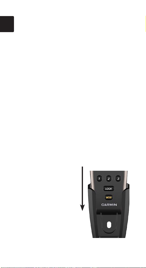
To insert the remote
control into the cradle:
1. Slide the remote control
into the top of the cradle.
2. Push the remote control
into the cradle until you
feel it lock in place.
EN–4 Instructions
To remove the remote control from the
cradle:
1. Push up on the bottom of the remote control to
release it from the cradle.
2. Pull the remote control out of the cradle.
EN
Mounting the GHC 10 Remote
Control Cradle
You can either mount the GHC 10 Remote Control
cradle on a surface such as the dashboard of your
boat or install a button on the back to be used with
a belt clip (included) or other carrying accessories
(sold separately).
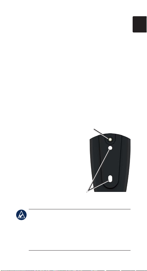
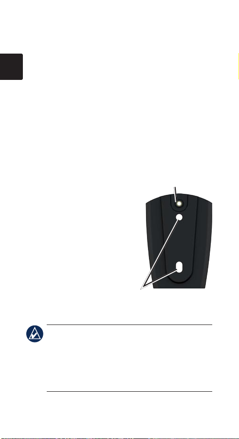
Attach belt clip button
To surface-mount the
cradle:
1 Mount the cradle
97/8 in. (250 mm) from
a magnetic compass to
avoid interference.
2. Using the cradle as a
template, mark the pilot
hole locations on the
surface on which you will
be mounting the cradle.
Attach belt clip button
Mounting screw holes
Mounting screw holes
NOTE: If you are mounting the cradle in
berglass, it is recommended to use a countersink
bit to drill a clearance counterbore through only
the top gel-coat layer. This will help to avoid any
cracking in the gel-coat layer when the screws are
tightened.
Instructions EN–5

3. Drill 1/8 in. (3.2 mm) pilot holes.
EN
4. Use the two included mounting screws to
attach the cradle to the mounting surface.
To attach the belt-clip button and belt clip:
1. Screw the belt-clip button into the back of the
cradle.
2. Snap the button into the belt clip or other
carrying accessory (sold separately).
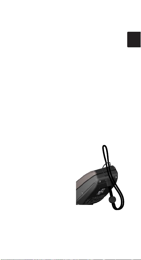
Using the GHC 10 Remote
Control Lanyard
Use the GHC 10 Remote Control lanyard to carry
the GHC 10 Remote Control. The remote control
can still be placed in the cradle with the lanyard
installed.
To attach the lanyard to
the remote control:
1. Thread the thin loop on
the lanyard through the
eyelet on the bottom of
the remote control.
2. Thread the larger part
of the lanyard through
the thin loop and pull
until it is snug.
EN–6 Instructions

Basic Operation
EN
Pairing the GHC 10 Remote Control
with a GHC 10 Unit
The GHC 10 Remote Control can be used with
only one GHC 10 unit. To use the remote control
with a GHC 10 unit, you must rst pair it with the
GHC 10 unit.
To pair the remote control with a GHC 10
unit:
1. On the GHC 10 unit, select Menu > Setup >
Remote > Search for Remote. “Enabled” will
be displayed on the menu of the GHC 10 unit.
2. On the remote control, press and hold both
double arrow buttons ( ) until the word
“PAIRING” appears on the remote control
screen. Release the double arrow buttons on
the remote control.
3. The GHC 10 unit will display “New Wireless
Remote Found”. Select Connect to pair the
remote control with the GHC 10 unit.
Engaging and Disengaging the
GHP 10 Autopilot System With the
GHC 10 Remote Control
To engage or disengage the GHP 10 autopilot
system with the GHC 10 Remote Control, press
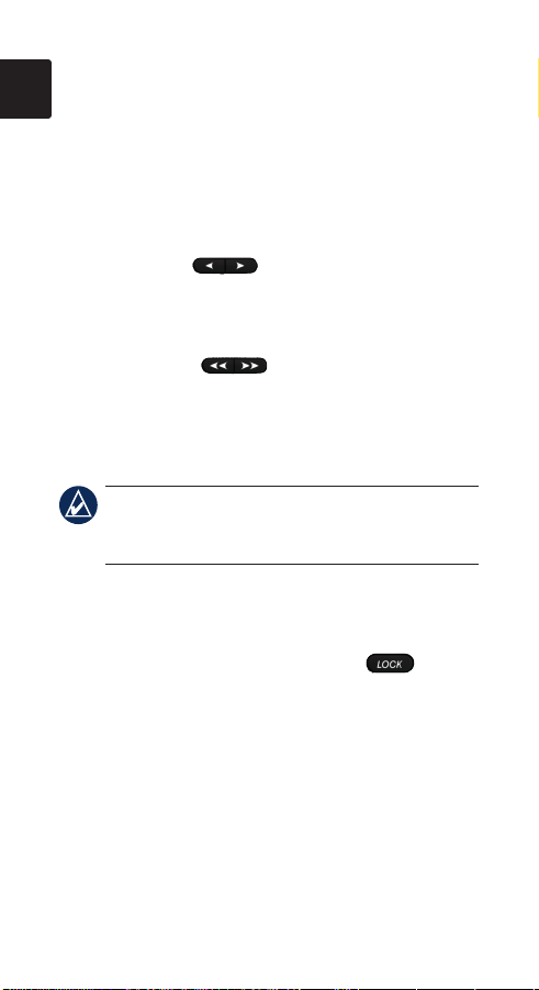
the STBY/ENGAGE ( ) button.
Instructions EN–7
Manually Adjusting the Heading of
EN
the GHP 10 Autopilot System With
the GHC 10 Remote Control
You can manually adjust the heading of the
autopilot system with the arrow buttons on the
GHC 10 Remote Control.
Single arrows ( )—Manually adjusts the
heading using “Rudder” steering. This adjusts the
heading in increments of 1°.
Double arrows ( )—Manually adjusts the
heading using “Step” steering. This adjusts the
heading by the “Step Turn Size” dened on the
GHC 10 unit.
NOTE: For more information on “Rudder” and
“Step” steering, see the GHP 10/GHC 10 Quick
Start Manual.
Locking and Unlocking the GHC 10
Remote Control Buttons
Press and release the LOCK button ( ) to
lock all the GHC 10 Remote Control buttons
except the MOB button. When locked, the remote
control will beep when you press any button on
the remote control other than MOB button.
Press and release the LOCK button to unlock the
remote control buttons.
EN–8 Instructions
Advanced Operation
EN
Understanding Programmable
Buttons
There are three programmable buttons
( ) on the GHC 10 Remote Control. You
can assign steering patterns or GPS patterns to
each button. In addition to patterns, you can assign
a direction-control toggle (forward and reverse) to
one of the programmable buttons.
Assigning Patterns or Actions to the
Programmable Buttons
Use the GHC 10 unit to assign patterns or actions
to each programmable button on the remote.
To assign a pattern or an action to a
programmable button:
1. On the GHC 10 unit, select Menu > Setup >
Remote.
2. Select the button to which you want to assign a
pattern or an action.
3. Choose a steering pattern or a GPS pattern.
OR
Choose Direction Control.
Instructions EN–9
Using Patterns Assigned to the
EN
Programmable Buttons
After you assign patterns to the programmable
buttons, you can use them when the autopilot
is either engaged or disengaged. Using a
programmable button to begin a pattern will
automatically engage the autopilot.
To use a pattern assigned to a
programmable button:
1. On the GHC 10 Remote Control, press the
programmable button assigned to the pattern
you want to use.
2. The pattern appears on the remote control
screen. Press the left or right single or double
arrow button ( or ) to choose
the direction and begin the pattern. If the
pattern does not require you to choose a
direction, press the programmable button again
to begin the pattern.
To use a button programmed with direction
control:
1. Bring the boat to a stop and disengage the
autopilot before changing throttle directions.
2. On the GHC 10 Remote Control, press the
programmable button assigned to the direction
control to toggle between forward and reverse.
EN–10 Instructions
Using MOB (Man Overboard)
Use the MOB button on the GHC 10 Remote
EN
Control to start the Man Overboard pattern on the
GHC 10 unit.
To use the MOB:
1. Press the MOB button on the remote control.
(You can press the MOB button even when the
buttons are locked.)
2. The name MOB and the image of the MOB
pattern will appear on the screen of the remote
control. Press the left or right single or double
arrow button ( or ) to choose
the direction and begin the MOB pattern.
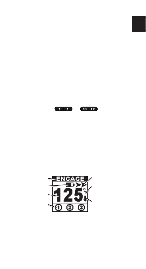
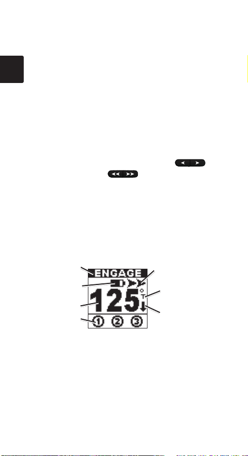
Understanding the Screen of
the Remote Control
The screen on the GHC 10 Remote Control
provides real-time information about the GHP 10/
GHC 10.
Autopilot status
Battery level
Heading
Programmable
button status
Instructions EN–11
Steering indicator
Heading source
(magnetic or true)
Steering direction
indicator (only
visible in reverse)

LCD screen notes:
EN
When running a pattern, the symbol
•
associated with the pattern appears above
the heading source.
If the action assigned to a programmable
•
button is not available, the button is marked
with an X ( ).
Specications
Physical size: W × H × D: 53/4 × 23/
(146 × 52 × 31 mm)
Weight: 3.74 oz. (106 g) without batteries,
5.43 oz. (154 g) with batteries
Material: Fully gasketed, high impact alloy
Water-resistance: Waterproof to IEC 529-IPX-7
RF Frequency: 2.457 GHz
Battery life: Up to 400 hours with no backlight
usage; up to 25 hours with
constant backlight usage.
Operating temperature:
5°–158°F
(from 15° to 70°C)
Storage temperature: from -40° to 185°F
(from -40° to 85°C)
Backlight: Automatic; disabled when the buttons
are locked
Compass-safe distance: 97/8 in. (250 mm)
× 17/32 in.
64
EN–12 Instructions
Avertissements
Vous êtes responsable de la sécurité de
•
la navigation et du pilotage de votre
bateau. Le GHP 10 est un outil qui optimise
votre capacité de pilotage du bateau. Il ne
vous dégage pas de votre responsabilité de
sécurité d’utilisation du bateau. Evitez tout
danger de navigation et ne relâchez pas votre
surveillance du gouvernail.
Soyez toujours prêt à reprendre les
•
commandes manuelles du bateau.
•
Apprenez à utiliser le GHP 10 sur mer calme
et sans danger.
•
Utilisez avec précautions le GHP 10 à des
vitesses élevées et à proximité de dangers
comme les quais, les poteaux et d’autres
bateaux.
FR
Instructions FR–13
Liste des éléments fournis
Avant d’installer l’appareil, vériez que l’emballage
contient les éléments suivants. Si certains
FR
composants sont manquants, contactez votre
revendeur Garmin®.
Contenu de l’emballage
standard
Télécommande
•
GHC 10
Deux socles de
•
télécommande
GHC 10
Vis de montage de
•
socle
Bouton de clip à
•
ceinture
Clip à ceinture
•
Cordon tour de cou
•
Cordon pour poignet
•
Outils requis (pour
xer le socle sur
surface)
Tournevis cruciforme
•
Perceuse et foret de
•
3,2 mm (1/8 po)
A propos de la télécommande
GHC 10
La télécommande GHC 10 est un accessoire du système
de pilote automatique GHP 10. Pour obtenir des
informations complètes sur l’utilisation du système de
pilote automatique GHP 10 ainsi que des avertissements
importants, consultez le Manuel de démarrage rapide
du GHP 10/GHC 10.
Consultez le guide Informations importantes sur
le produit et la sécurité
produit, pour prendre connaissance des avertissements
et autres informations sur le produit.
Instructions FR–14
inclus dans l’emballage du

Installation
Installation des piles dans la
FR
télécommande GHC 10
La télécommande GHC 10 requiert deux piles AA.
Pour installer les piles dans la
télécommande :
1. Retirez le cache du compartiment à piles en
soulevant et en tournant l’anneau de verrouillage
dans le sens inverse des aiguilles d’une montre.
2. Insérez les piles comme indiqué sur le schéma de la
télécommande.
Utilisation du socle de la
télécommande GHC 10 Garmin
Le socle de la télécommande GHC 10 sert de support à
la télécommande GHC 10 ; il peut soit être monté sur
une surface telle que le tableau de bord, soit être xé à
un clip à ceinture.
Pour mettre en place la
télécommande sur son
socle :
1. Insérez la télécommande
dans la partie supérieure du
socle.
2. Faites-la glisser dans le
socle jusqu’à ce qu’elle soit
en place.
Instructions FR–15
Pour retirer la télécommande de son socle :
1. Exercez une pression sur le bas de la
télécommande pour la sortir du support.
2. Retirez la télécommande du support.
FR
Montage du socle de la
télécommande GHC 10
Vous pouvez monter le socle de la télécommande
GHC 10 sur une surface telle que le tableau de bord de
votre bateau ou xer un bouton à l’arrière du socle
permettant d’attacher ce dernier à un clip à ceinture
(inclus) ou à un autre accessoire de transport (vendu
séparément).
Pour xer le socle sur
surface :
1. Montez le support à une
distance de 250 mm
(97/8 po) d’un compas
magnétique, pour éviter
toute interférence.
2. Utilisez le socle comme
modèle, en marquant les
emplacements des trous
d’implantation sur la
surface sur laquelle vous souhaitez monter le socle.
Bouton de xation au
Bouton de xation au
clip à ceinture
clip à ceinture
Orices pour vis de montage
Orices pour vis de montage
REMARQUE : si vous montez le socle sur de la
bre de verre, nous vous recommandons d’utiliser
un foret de fraisage pour percer un trou à fond plat à
travers le revêtement de la couche supérieure. De cette
manière,vous ne risquez pas de ssurer le revêtement
au moment du serrage des vis.
Instructions FR–16
3. Percez des trous d’implantation de 3,2 mm (1/8 po).
4. Utilisezlesdeuxvisdemontageinclusespourxer
le socle sur la surface de montage.
Pour xer le bouton du clip à ceinture au clip à
ceinture :
1. Vissez le bouton du clip à ceinture à l’arrière du
socle.
2. Mettez le bouton en place sur le clip à ceinture
ou sur un autre accessoire de transport (vendu
séparément).
FR
Utilisation du cordon de la
télécommande GHC 10
Utilisez le cordon de la télécommande GHC 10
pour transporter la télécommande GHC 10. La
télécommande peut être placée sur son socle même
quand le cordon est en place.
Pour attacher le cordon à la télécommande :
1. Faitespasserlane
boucle du cordon
à travers l’œillet
situé à l’arrière de la
télécommande.
2. Faites passer l’autre
extrémité du cordon à
travers la boucle et tirez à
fond.
Instructions FR–17

Fonctions de base
Couplage de la télécommande GHC 10
FR
avec un GHC 10
La télécommande GHC 10 peut être utilisée
uniquement avec un GHC 10. Pour utiliser la
télécommande avec un GHC 10, vous devez au
préalable coupler les deux éléments.
Pour coupler la télécommande avec le
GHC 10 :
1. Sur le GHC 10, sélectionnez Menu >
Conguration > Télécommande > Rechercher
une télécommande.L’option«Activé»s’afche
dans le menu du GHC 10.
2. Sur la télécommande, appuyez sur les boutons à
doubleèche( ) et maintenez-les enfoncés
jusqu’àcequelemot«PAIRING»s’afchesur
l’écran de la télécommande. Relâchez les boutons à
doubleèchedelatélécommande.
3. Le message « Nouvelle télécommande trouvée »
s’afcheàl’écranduGHC10.Sélectionnez
Connecter pour coupler la télécommande avec le
GHC 10.
Activation et désactivation du système
de pilote automatique GHP 10 à l’aide de
la télécommande GHC 10
Pour activer ou désactiver le système de pilote
automatique GHP 10 à l’aide de la télécommande
GHC 10, appuyez sur le bouton STBY/ENGAGE
( ).
Instructions FR–18
Réglage manuel du cap du système de
pilote automatique GHP 10 à l’aide de la
télécommande GHC 10
Vous pouvez régler manuellement le cap du système
de pilote automatique GHP 10 à l’aide des boutons
à simples ou doubles èches de la télécommande
GHC 10.
Simples èches ( ) : permettent de régler
manuellement le cap à l’aide de la navigation « par
degrés ». Le réglage du cap se fait par incréments de 1°.
Doubles èches ( ) : permettent de régler
manuellement le cap à l’aide de la navigation « par
paliers ». Le réglage du cap se fait par « Taille de virage
par étapes » dénie sur le GHC 10.
REMARQUE : pour de plus amples informations
sur la navigation « par degrés » et « par paliers »,
consultez le Manuel de démarrage rapide du GHP 10/
GHC 10.
FR
Verrouillage et déverrouillage des
boutons de la télécommande GHC 10
Appuyez sur le bouton LOCK ( ), puis relâchezle pour verrouiller tous les boutons de la télécommande
GHC 10 excepté le bouton MOB. Une fois les boutons
verrouillés, un signal sonore est émis lorsque vous
appuyez sur un bouton de la télécommande autre que le
bouton MOB.
Appuyez sur le bouton LOCK, puis relâchez-le pour
déverrouiller tous les boutons de la télécommande.
Instructions FR–19

Fonctions avancées
Présentation des boutons
FR
programmables
La télécommande GHC 10 comporte trois boutons
programmables ( ). Vous pouvez attribuer des
modèles de navigation ou des modèles de navigation
GPS à chaque bouton. Outre des modèles, vous
pouvez attribuer un basculement de la commande
de direction (en avant et en arrière) à un des boutons
programmables.
Attribution de modèles ou d’actions aux
boutons programmables
Utilisez le GHC 10 pour attribuer des modèles ou
des actions à chaque bouton programmable de la
télécommande.
Pour attribuer un modèle ou une action à un
bouton programmable :
1. Sur le GHC 10, sélectionnez Menu >
Conguration > Télécommande.
2. Sélectionnez le bouton auquel vous voulez attribuer
un modèle ou une action.
3. Choisissez un modèle de navigation ou un
modèle GPS.
OU
Choisissez
Commande direction.
Instructions FR–20
Utilisation de modèles attribués aux
boutons programmables
Après avoir attribué des modèles aux boutons
programmables, vous pouvez les utiliser soit lorsque
le pilote automatique est activé, soit lorsqu’il est
désactivé. L’utilisation d’un bouton programmable pour
lancer un modèle de navigation active automatiquement
le pilote automatique.
Pour utiliser un modèle attribué à un bouton
programmable :
1. Sur la télécommande GHC 10, appuyez sur le
bouton programmable attribué au modèle que vous
voulez utiliser.
2. Le modèle apparaît sur l’écran de la télécommande.
Appuyezsurleboutonàsimpleèche(
ouàdoubleèche(
pour choisir la direction du modèle et l’activer. Si le
modèle ne requiert pas la sélection d’une direction,
appuyez de nouveau sur le bouton programmable
pour activer le modèle.
), à gauche ou à droite,
Pour utiliser un bouton programmé avec
une commande de direction :
1. Immobilisez le bateau et désactivez le pilote
automatiqueavantdemodierlesdirections
d’accélération.
2. Sur la télécommande GHC 10, appuyez sur le
bouton programmable attribué à la commande de
direction pour basculer du mode avant au mode
arrière.
FR
)
Instructions FR–21
Utilisation de la fonction MOB
(homme à la mer)
Utilisez le bouton MOB de la télécommande GHC 10
FR
pour activer le modèle Homme à la mer sur le GHC 10.
Pour utiliser la fonction MOB :
1. Appuyez sur le bouton MOB de la télécommande.
(Vous pouvez appuyer sur le bouton
lorsque les boutons sont verrouillés.)
2. Le nom « MOB » et l’image du modèle MOB
apparaissent à l’écran de la télécommande.
Appuyezsurleboutonàsimpleèche(
ouàdoubleèche(
pour choisir la direction du modèle MOB et l’activer.
MOB même
), à gauche ou à droite,
Présentation de l’écran de la
télécommande
L’écran de la télécommande GHC 10 fournit des
informations en temps réel sur le GHP 10/GHC 10.
)
Etat du pilote
automatique
Niveau de charge
de la batterie
Cap
Etat de bouton
programmable
Instructions FR–22
Indicateur de
navigation
Source de cap
(magnétique ou réel)
Indicateur de
direction de
navigation (visible
uniquement en mode
arrière)
Remarques sur l’écran LCD :
Lors de l’exécution d’un modèle, le symbole qui
•
lui est associé apparaît au dessus de la source
de cap.
Si l’action assignée à un bouton programmable
•
n’est pas disponible, le bouton est signalé par un
X (
).
Caractéristiques techniques
Dimensions : L × H × P : 146 × 52 × 31 mm
(53/4 × 23/64 × 17/32 po)
Poids : 106 g (3,74 oz) sans les piles,
154 g (5,43 oz) avec les piles
Matériau : alliage hermétique résistant aux
chocs
Etanchéité : étanche, conformément à la norme
IEC 529-IPX-7
Radiofréquence : 2,457 GHz
Autonomie : jusqu’à 400 heures sans
rétroéclairage ; jusqu’à 25 heures
avec rétroéclairage utilisé continuellement.
Température de fonctionnement : de 15 °C à 70 °C
(de 5 °F à 158 °F)
Température de stockage : de -40 °C à 85 °C
(de -40 °F à 185 °F)
Rétroéclairage : automatique ; désactivé lorsque les
boutons sont verrouillés
Distance de sécurité du compas : 250 mm (97/8 po)
FR
Instructions FR–23
IT
Avvertenze
Ogni utente è da ritenersi responsabile per
•
una navigazione sicura e prudente con la
propria imbarcazione. Il sistema GHP 10
è uno strumento in grado di migliorare le
capacità di navigazione con l’imbarcazione
da parte dell’utente, ma non lo esime dalla
responsabilità di navigare in modo sicuro
con l’imbarcazione. Evitare rischi durante
la navigazione e non lasciare mai il timone
incustodito.
Tenersi sempre pronti a riprendere il
•
controllo manuale dell’imbarcazione in modo
tempestivo.
Apprendere le modalità d’uso del sistema
•
GHP 10 in acque calme e tranquille.
Usare cautela durante l’uso del sistema GHP
•
10 a velocità elevate vicino ad elementi di
rischio in acqua, come moli, piloni e altre
imbarcazioni.
IT–24 Istruzioni
 Loading...