

Page 1

SILENT
HUNTER
CONTENTS
WAR BENEATH THE WAVES . . . . . . . . . . . 1
What Comes with This Game . . . . . . . . . . 1
Using the Mouse . . . . . . . . . . . . . . . . . . . . . 2
STARTING THE GAME . . . . . . . . . . . . . . . . 2
Single Missions . . . . . . . . . . . . . . . . . . . . . 3
Mission Customization . . . . . . . . . . . . . . . 4
Realism . . . . . . . . . . . . . . . . . . . . . . . . . . . . 6
Submarine Class Selection . . . . . . . . . . . 10
Victory or Defeat . . . . . . . . . . . . . . . . . . . 10
THE CAREER MENU . . . . . . . . . . . . . . . . . 10
Starting a Career . . . . . . . . . . . . . . . . . . . 10
Best Careers . . . . . . . . . . . . . . . . . . . . . . . 10
Main Menu . . . . . . . . . . . . . . . . . . . . . . . . 10
Continue a Career . . . . . . . . . . . . . . . . . . 11
Base Menu Options . . . . . . . . . . . . . . . . . 11
CONTROLS . . . . . . . . . . . . . . . . . . . . . . . . . 14
The Smart Mouse Pointer . . . . . . . . . . . . 14
Using the Function Keys (F1 - F10) . . . . . 14
Setting the Detail Level . . . . . . . . . . . . . . 14
Control Buttons . . . . . . . . . . . . . . . . . . . . 15
COMMANDING THE SUBMARINE . . . . . . 16
Captain’s Cabin . . . . . . . . . . . . . . . . . . . . 17
Charts . . . . . . . . . . . . . . . . . . . . . . . . . . . . 18
Radar . . . . . . . . . . . . . . . . . . . . . . . . . . . . . 20
TDC (Torpedo Data Computer) . . . . . . . . 22
Gauges Station . . . . . . . . . . . . . . . . . . . . . 23
Up Scope (or Periscope Station) . . . . . . . 27
Bridge . . . . . . . . . . . . . . . . . . . . . . . . . . . . 33
Status and Torpedo Room Stations . . . . . 38
SUBMARINES . . . . . . . . . . . . . . . . . . . . . . . 40
S
ILENTHUNTER
U.S. Torpedoes . . . . . . . . . . . . . . . . . . . . . 50
Radar and Bathythermograph . . . . . . . . . 50
Deck Guns/AA Guns . . . . . . . . . . . . . . . . . 50
TORPEDOES . . . . . . . . . . . . . . . . . . . . . . . 50
Shortages . . . . . . . . . . . . . . . . . . . . . . . . . 50
Torpedo Types . . . . . . . . . . . . . . . . . . . . . 51
Problems Arise . . . . . . . . . . . . . . . . . . . . . 52
The New Hope . . . . . . . . . . . . . . . . . . . . . 53
THE COMMANDERS . . . . . . . . . . . . . . . . . 54
Vice Admiral Charles Lockwood . . . . . . . 54
Dudley W. “Mush” Morton
and the Wahoo . . . . . . . . . . . . . . . . . . . . . . . 55
Lawson P. “Red” Ramage
and the Parche . . . . . . . . . . . . . . . . . . . . . 55
Richard H. O’Kane and the Tang . . . . . . . 56
APPENDIX A:
U.S.S. SKATE AND THE FIFTH FLEET . . 57
On to the Gilberts . . . . . . . . . . . . . . . . . . 61
Operations Flintlock and Hailstone . . . . 64
APPENDIX B:
TACTICS . . . . . . . . . . . . . . . . . . . . . . . . . . . 68
Torpedo Attack . . . . . . . . . . . . . . . . . . . . . 68
Basic Approach Objective . . . . . . . . . . . . . 68
APPENDIX C:
THE FIRE CONTROL PROBLEM . . . . . . . 73
WEAPONS DATA . . . . . . . 50
This product has been rated by the Entertainment Software Rating Board. For information about the ESRB rating, or to comment about the appropriateness of the
rating, please contact the ESRB at 1-800-771-3772.
Page 2
SILENT
HUNTER
1 WAR BETWEEN THE WAVES
WAR BENEATH THE WAVES
The December 7, 1941 attack on Pearl Harbor damaged or destroyed nineteen
capital ships of the U.S. Navy’s Pacific Fleet. This left the aged and outgunned
forces of the Asiatic Fleet as the first line of defense against the oncoming might of
the Japanese Navy. One force that emerged from the attacks on Pearl Harbor and
Cavite, virtually unscathed and ready to carry the war to the enemy, were the submariners of the Fleet Scouting Force. The 51 submarines of the Asiatic and Pacific
fleets were ordered to “...
J
APAN
. Y
OU WILL SINK OR DESTROY ENEMY SHIPPING WHEREVER ENCOUNTERED
Authorized to sink any vessel bearing the “Rising Sun” of Japan, the untried
men of the Pacific submarine forces quickly became hunters of the largest
prey around. Now, you too can stalk the tankers and freighters that carry the
lifeblood of the empire, the destroyers, cruisers and carriers that are the
weapons of war. You can become a Silent Hunter.
EXECUTE UNRESTRICTED AIR AND SUBMARINE WARFARE AGAINST
.”
SILENT
HUNTER
2 WAR BETWEEN THE WAVES: What Comes with this Game
by William P. “Bud” Gruner, who commanded SS 305, the U.S.S. Skateon her
third, fourth and fifth war patrols. Appendix A is entitled “The U.S.S. Skate and
the Fifth Fleet.” Appendix B provides a brief overview of submarine tactics.
Appendix C describes the formulas for calculating a manual firing solution.
Using the Mouse
In this manual, the term “click” means to move the mouse pointer over the
desired area of the screen and press either the left or right mouse button.
The mouse pointer changes shape depending on the type of action which can
be taken. “Left-click” or “right-click” means to move the mouse pointer to
the desired position and press the appropriate button.
Left-clicking is used to change stations aboard the submarine, set controls,
fire weapons, and alter preferences. Left-clicking handles most of the controls in S
the current mission can be ended.
ILENTHUNTER
. Right-clicking opens the Abort Mission box where
What Comes with This Game
The game box should contain this user’s manual, a S
a data card. This user’s manual explains game controls and contains historical
information about submarine warfare in the Pacific Theater during World War II.
To install the game, please refer to the data card.
This manual contains a description of how to use all of the controls that this
simulation provides to realistically reproduce the feeling of hunting and being
hunted by the ships of the Imperial Japanese Navy. It also contains several
appendices which provide more insights into the reality of submarine warfare
ILENTHUNTER
CD-ROM, and
STARTING THE GAME
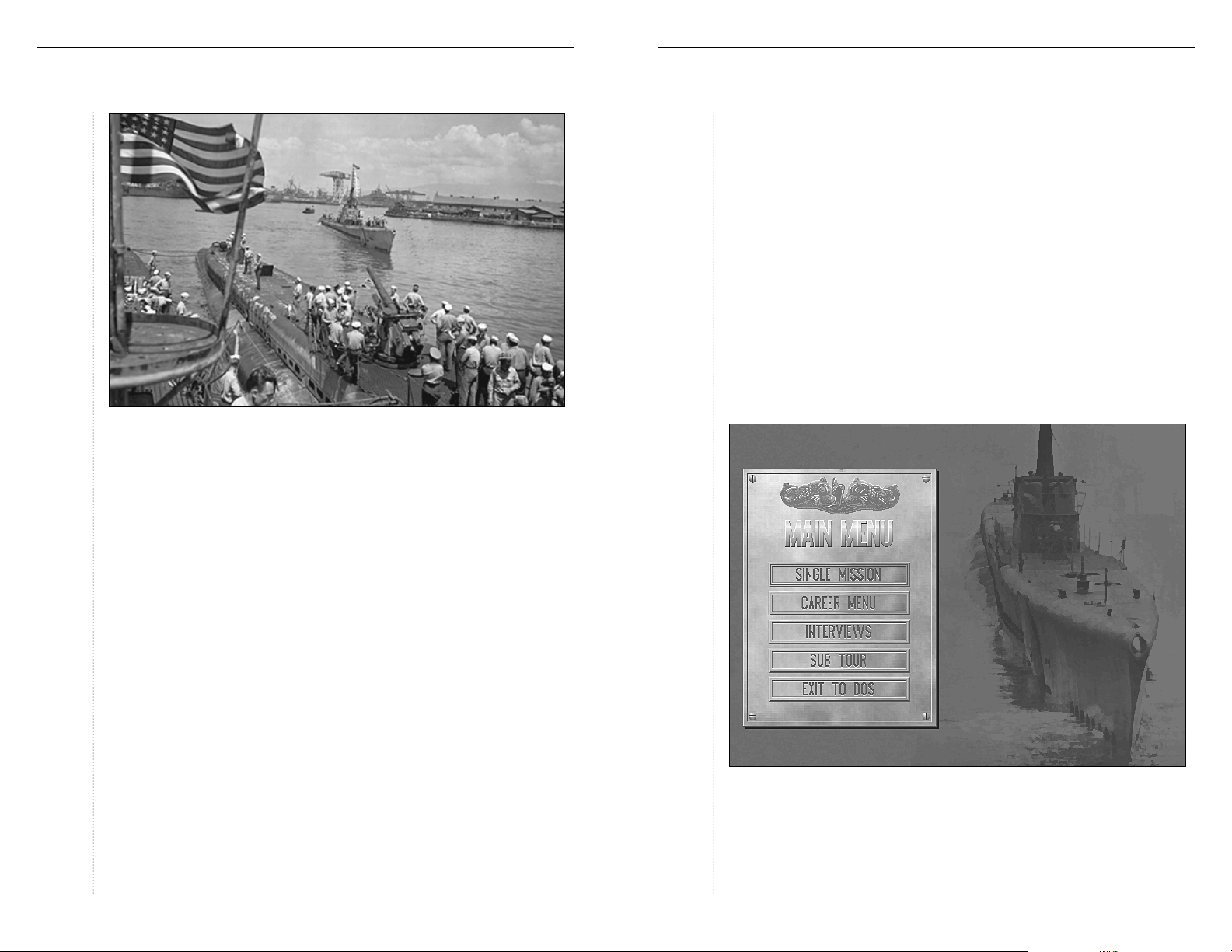
After the opening animation, two choices are offered for playing S
a Single Missionor the Career Menu. In addition, there are options to view an
interview with William P. “Bud” Gruner, who commanded the U.S.S. Skate;
take a multimedia tour of the U.S.S. Pampanito ; or Exit to DOS.
ILENTHUNTER
,
Page 3
SILENT
HUNTER
3 STARTING THE GAME: Single Mission
SILENT
HUNTER
4 STARTING THE GAME: Single Mission
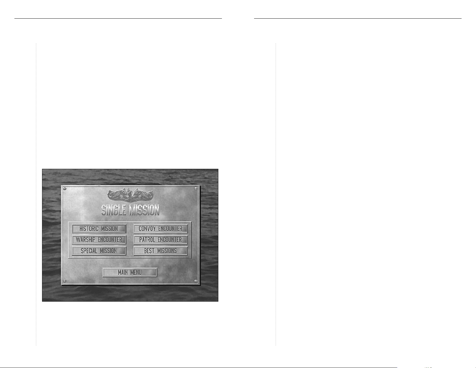
Single Missions
Choosing Single Mission presents an option to perform one of five different
kinds of authentic missions that U.S. submarines undertook during WWII.
In addition to seeking out and destroying enemy warships and cargo ships,
U.S. submarines performed other valuable services such as rescuing
downed pilots. All of the types of missions except for the Historic Mission
selection are generated randomly, and can be customized prior to play.
These missions will begin with some form of contact notification regarding
the enemy, either a radar contact, a hydrophone bearing, or a lookout
report. The mission ends when the submarine is out of contact with all
enemy ships. This might be because the submarine has sunk all the enemy
ships, has disengaged or been outrun by the enemy, or has been destroyed.
At this point a scoring screen appears which correlates the level of realism
and the number of enemy vessels damaged or sunk and presents the score.
Left-clicking on the Exit button returns you to the Single Mission menu.
The Historical Mission menu automatically defaults to the top mission on
the menu, so go ahead and make any realism changes prior to selecting the
mission to be played.
Convoy Encounter
During WWII U.S. submarines sank nearly 5,000,000 tons of Japanese merchant shipping, accounting for over 1100 confirmed sinkings. This was the
most likely type of encounter during the war.
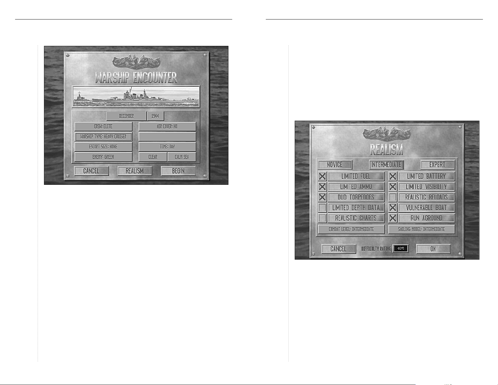
Warship Encounter
This mission consists of intercepting and attacking an Imperial Japanese
Navy task force. Aircraft carriers were the highest priority target for the
submarine force, followed by battleships and escort carriers.
Patrol Encounter
Encounter a Japanese anti-submarine (ASW) patrol searching for U.S. submarines.
Lifeguard Duty
Over 500 aviators owe their lives to the men of the Silent Service. Submarines
were frequently positioned to recover downed pilots at the scene of surface
engagements, such as Midway, or during large air strikes. A downed aviator
can only survive a limited time in the water, and the submarine’s task is to
effect a rescue before the sea claims him or the enemy captures him.
Historic Mission
This option presents the opportunity to test your skills against those of historic submariners in encounters that defined what it meant to be a member
of the Silent Service. The available missions are listed in the menu, with
the appropriate briefing listed below the mission menu.
Mission Customization
After a mission type has been selected, several mission variables may be
chosen. Each type of mission has some of the following options available.
Date
The date affects the location of the encounter, the number and type of ships
encountered, and the equipment available to both sides. For more information regarding the types of equipment available for any given month of the
war, see the “S
Crew Quality
Crew quality affects the ability of the crew to operate the submarine. Reload
time, dive time, lookout sighting distances, and other factors are all determined by the crew quality setting. The crew can range from green to elite.
ILENTHUNTER
Weapons Data” table on page 50.
Page 4
SILENT
HUNTER
5 STARTING THE GAME: Mission Customization
Convoy Size
The size of the encountered convoy, small, medium, or large.
SILENT
HUNTER
6 STARTING THE GAME: Mission Customization
Time of Day
Select whether to begin the mission at Dawn, during the Daytime, at Dusk
or during the Night. Submarines equipped with radar could operate on the
surface at night much more readily than could earlier submarines.
Weather
The weather affects the speed of ships and the amount of visibility. Heavy
seas affect the submarine’s stability near the surface, while fog can be a
commander’s best friend.
Warship Type
Capital ships travelled in a main body of vessels, usually with an interior
screen of cruisers and an exterior screen of destroyers. Select between carrier, battleship, cruiser, and light cruiser task forces.
Escort Size/Patrol Threat
These options determine the number and probability of encountering some
form of patrol vessel or escort.
Enemy Quality
This setting determines how tough the enemy is. Gun and depth charge
attack accuracy, lookout sighting distance, and overall coordination of attack
are controlled by this setting. Enemy crews can be green, veteran, or elite.
Air Cover/Threat
Task forces and occasionally convoys were supplied with air cover. Other missions run the risk of encountering an aerial patrol. These settings determine
the number and probability of encountering some form of air cover.
Realism
The level of realism experienced while playing S
fied for both single missions and careers. This is done using the Realism
screen, which is available from all Single Mission screens and when the
submarine is in port during campaign games. With all Realism settings
selected, the simulation is as close to real as is possible!
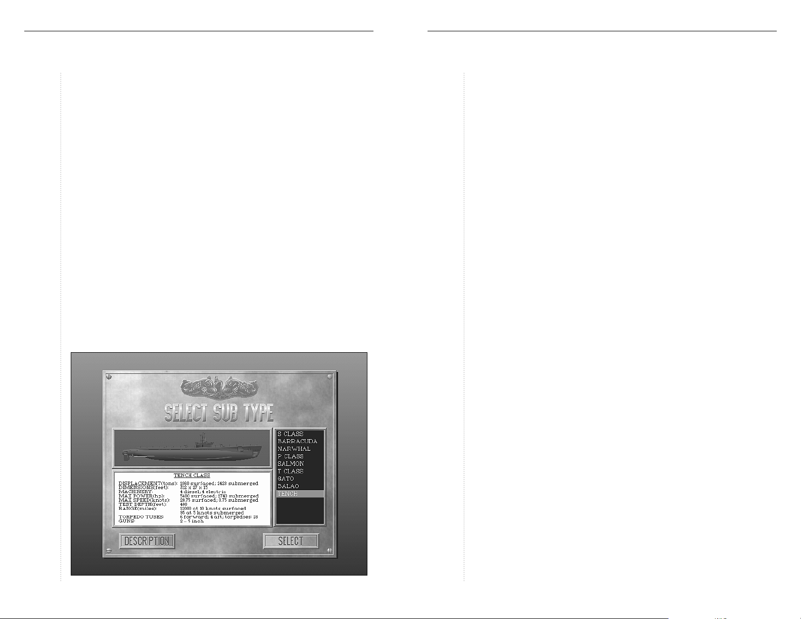
Overall settings
At the top of the Realism menu are three buttons: Novice, Intermediate, and
Expert. These buttons are quick ways to select specific sets of play conditions.
Novice level lowers the combat and sailing model levels to novice, and turns
off all realism settings except the vulnerability of the submarine.
ILENTHUNTER
can be modi-
Page 5

SILENT
HUNTER
7 STARTING THE GAME: Realism
SILENT
HUNTER
8 STARTING THE GAME: Realism
Intermediate level lowers the combat level and sailing models to “Intermediate,”
and turns off the Dud Torpedo, Realistic Reloads, Limited Depth Data, and
Realistic Charts settings.
Expert level implements every possible realism setting, duplicating live conditions during WWII as closely as possible. The combat level is set to
“Advanced” and the submarine maneuvers realistically.
Other Realism Settings
There are options other than the three preset levels. Ten settings can be
toggled on or off and each of these settings has the effect of reducing the
realism by a certain percentage when turned off. The Combat Level and
Sailing Model settings have more than two levels and each of these levels
also change the overall Difficulty Rating.
Limited Fuel
The Limited Fuel setting has a small effect on Single Mission games, but is
a serious consideration for the Campaign Game. Refueling can only be performed by a submarine tender or at a base. Turning this setting off reduces
the realism factor by 10%.
Limited Battery
With Limited Battery turned off, the submarine never needs to surface to recharge the batteries. Turning this setting off reduces the realism factor by 30%.
Limited Ammo
The submarines simulated by S
rounds for the deck gun and twelve to twenty-eight torpedoes. When
turned off, there is an unlimited supply of both types of munitions. Turning
this setting off reduces the realism factor by 50%.
ILENTHUNTER
normally carried one hundred
Limited Visibility
With this option on, only ships actually visible to the crew will appear on
the map screen at the Charts station. If the submarine is submerged with
the periscope lowered, only the most recent observed contact will be shown
on the map. With this setting off, all ships will be shown on the map.
Turning this setting off reduces the realism factor by 30%.
Dud Torpedoes
From the beginning of the war until late in 1943, a series of problems with
the torpedoes caused a significant number of them to fail. With this setting
off, torpedoes are always reliable, but realism drops by 15%. For more
details of the torpedo problems, see the “Torpedoes” section on page 50.
Realistic Reloads
The Realistic Reloads setting toggles the torpedo tube reload time between
two minutes and a more realistic time that is also affected by crew quality.
Turning this setting off reduces the realism factor by 10%.
Limited Depth Data
With Limited Depth Data toggled on, the Depth Gauge indicates only how
deep the submarine has gone. There is no information available other than
the chart about how deep the waters are in that particular part of the ocean.
When toggled off, an additional gauge appears at the Gauges station entitled
“Depth Under Keel.” This indicates how deep the local waters are. Turning
this setting off reduces the realism factor by 5%.
Vulnerable Boat
Toggling Vulnerable Boat off eliminates the chance of the submarine taking damage, and correspondingly, reduces the Realism level by 80%.
Realistic Charts
The Realistic Charts setting controls the information that can be viewed at
the Charts station. With this setting toggled on, the chart shows only the
position of ships relative to the submarine, further modified by the Limited
Visibility setting. With this setting off, the Charts station shows torpedo
wakes and shell splashes as well. Turning this setting off reduces the realism factor by 10%.
Run Aground
With this setting turned off, the submarine can run aground without sustaining damage. This setting alters the Difficulty Rating by 5%.
Combat Level
Changing the Combat Level setting affects the accuracy and lethality of
both side’s weapons. The amount of information displayed on the map at
the Charts station, such as torpedoes, sonar pings, and gun hits, also
decreases at the advanced levels. The Realism rating is reduced 15% for
each level below Expert; from Expert to Advanced, to Intermediate and
finally Novice.
Page 6
SILENT
HUNTER
9 STARTING THE GAME: Realism
SILENT
HUNTER
10 STARTING THE GAME: Submarine Class Selection
Sailing Model
The Sailing Model controls the maneuverability of the submarine, affecting
dive time, maximum speed in heavy seas, turn rate and the likelihood of the
submarine running aground. Realism drops by 10% for each reduction in
level; from Realistic to Intermediate and from Intermediate to Novice.
Difficulty Rating
The Difficulty Rating is based on the effects of changing the realism settings
above. The mission score for completed missions is modified by the level of
realism chosen. The higher the realism setting, the higher the potential score.
Realism and Japanese Anti-Submarine Warfare
The realism setting determines the effectiveness of Japanese anti-submarine warfare (ASW). Throughout most of WWII, the Japanese Navy believed
that no submarine could dive below 200 feet and survive, so most of their
ASW efforts were expended at depths between 50 and 150 feet. In deep
water, U.S. fleet submarines could dive routinely below 200 feet and so
were able to survive repeated depth charge attacks.
In S
ILENTHUNTER
beyond 100%. This reflects Japanese ASW efforts that take into account the
full capabilities of U.S. submarines.
, the Combat Level setting can be used to increase realism
Submarine Class Selection
The type of submarine used can be selected for any of the single mission scenarios from a range of vessels available at that date. For Historic Missions, the
type of submarine used in the actual encounter is preselected. Each type of
submarine is displayed with statistical details by left-clicking on the list of
classes. Left-clicking on the Descriptionbutton toggles to a brief description.
Confirm the choice of a particular class by left-clicking on the Select button.
For more details about the submarine classes available in S
the “Submarines” section on page 40.
ILENTHUNTER
see
Victory or Defeat
The scenario continues until the submarine is destroyed or all enemy vessels
are beyond contact range. This can be because they have been sunk, they
have outrun the submarine, or the submarine has evaded all pursuit.
At this point a scoring screen appears which correlates the level or realism
and the number of enemy vessels damaged or sunk and presents the score.
Left-clicking on the Exit button returns you to the Single Mission menu.
THE CAREER MENU
The Career Menu is where the campaign game begins. Starting at any point
in the war, a series of war patrols are performed that can then be compared
to those of some of the greatest submariners ever.
Starting a Career
Enter the name of the submarine’s commander and select a starting month
and year for this career. Up to twenty different careers can be accommodated by the career roster; if all twenty positions have been used, a new
career must be entered over an older career.
The date chosen determines what classes of equipment are available to the
commander. This includes submarine classes, and features such as radar,
improved torpedoes, and radar detectors.
Best Careers
This option displays the top careers to date.
Main Menu
This button returns to the Main Menu.
Page 7
SILENT
HUNTER
11 THE CAREER MENU: Continue a Career
SILENT
HUNTER
12 THE CAREER MENU: Base Menu Options
Continue a Career
This button opens a menu where a saved career may be continued,
reviewed, or deleted. The Career Roster lists the names that have been
entered for the careers in progress. To continue to play a particular career,
left-click on it to highlight it and left-click on the Select button or double
left-click to resume that career.
The View button displays the progress of a highlighted career. The Delete
button deletes the highlighted career.
After selecting a career, the Base Menu appears.
Start War Patrol
This option begins a war patrol. The submarine will be assigned a patrol
area in which to operate. Any changes to the realism settings must be
done now, while still in port. See the “Realism” section on page 6 for
more information.
Prior to departure initial instructions are issued for any particular missions
the submarine is to undertake. While on the mission, occasional radio messages will update the commander of enemy activity in the area.
Ending a War Patrol
A war patrol continues until:
♦
The submarine is destroyed.
♦
The submarine is damaged beyond the ability of the crew to repair it.
♦
The submarine runs out of supplies (fuel and /or ammunition).
♦
The submarine is ordered back to base at the end of the patrol.
Depending on the success of the war patrol, the commander may be
rewarded. Success is measured in a variety of ways, and reassignment is
possible in cases of poor performance.
Tonnage
The primary yardstick of success for a submariner during WWII was ships
sent to the bottom, whether merchant or military. The tonnage sunk figure
does not include ships that were damaged but did not actually sink.
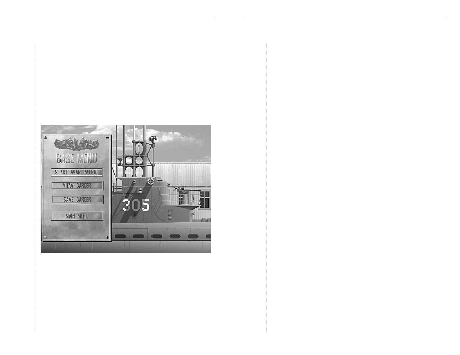
Base Menu Options
The campaign aspects of S
Menu — campaigns are made up of a series of war patrols. While at
base several activities are possible:
♦
Start a war patrol.
♦
View the top scores for commanders in that campaign.
♦
Examine the record of the active commander.
♦
Visit the Officer’s Club for news and rumors.
♦
Save the active career.
♦
Return to the Main Menu.
ILENTHUNTER
are managed from the Base
Score
The score takes into account ships damaged or sunk, the overall mission
difficulty, and the difficulty based on realism level. The score for damaged
ships is based on the amount of damage done. The higher the realism level,
the higher the score.
Promotion, Medals, and Awards
While referred to on board as “Captain,” officers commanding submarines
were all Lieutenant Commanders or Commanders; all officers of higher
rank either moved to a different command or were assigned shore duty. For
this reason, submarine commanders in S
in order to remain historically accurate. Reassignment for inadequate performance is always possible.
ILENTHUNTER
will not be promoted
Page 8
SILENT
HUNTER
13 THE CAREER MENU: Base Menu Options
Medals are awarded based on the results of a particularly productive war
patrol. The medals that are possible, in order of precedence are:
♦
Medal of Honor
♦
Distinguished Service Medal
♦
Navy Cross
♦
Silver Star
♦
Bronze Star
Submarine crews may also earn either a Presidential Unit Citation or a Unit
Citation if the overall record of the submarine is good and it has an exemplary war patrol.
View Career
The career of the active submarine commander can be viewed using this
option. In addition to the name of the commander’s submarine and the
base he is assigned to, useful information is shown including the number of
ships sunk, the total tonnage sunk, and any medals or commendations the
commander or submarine have been awarded.
SILENT
HUNTER
14 CONTROLS: The Smart Mouse Pointer
CONTROLS
The Smart Mouse Pointer
The submarine is managed using controls and displays at several stations
around the submarine which are accessed via the control room. Move the
mouse pointer until it changes from an arrow to the name of the station and
left-click to change the view. Each station is represented by one or more
screens. Moving the mouse pointer over the controls and gauges at each
station is the fastest way to determine which are controls and which are displays because the mouse pointer changes from an arrow to a reticule with a
word above it, such as SET, SELECT, or FIRE.
♦
Settings on dials are changed by moving the reticule to the desired
position on the dial and left-clicking.
♦
Buttons are pressed by moving the mouse pointer over the button and
left-clicking.
Using the Function Keys (F1 - F10)
The stations listed below can also be reached using the corresponding
function keys:
FUNCTION KEY STATION
F1 ................................... Control Room
F2.................................... Up Scope/Periscope
F3.................................... Target Bearing Transmitter
F4.................................... Bridge
F5.................................... Charts
F6.................................... Torpedo Data Computer
F7.................................... Gauges
F8.................................... Status
F9.................................... Radar
F10.................................. Logbook
Alt F4.............................. Deckgun
Setting the Detail Level
Once a mission or war patrol has begun, pressing Alt-D opens the Detail
Level box. Graphic features that enhance the appearance but may hinder
play of S
wakes can be toggled on or off using this box. In addition, visibility range
can be increased in increments of one mile using this control. Left-clicking
in the upper left corner returns to play.
ILENTHUNTER
such as clouds, waves, land texture, ship and torpedo
Page 9
SILENT
HUNTER
15 CONTROLS: Control Buttons
SILENT
HUNTER
16 CONTROLS: Control Buttons
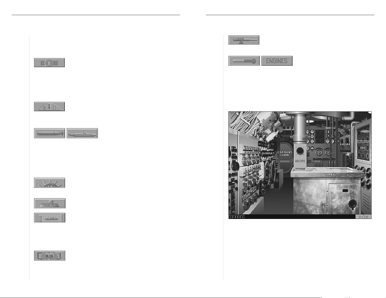
Control Buttons
At each station there are buttons at the bottom of the screen for changing
certain game settings, stations or accessing features.
The rate at which time passes can be changed by left-
clicking this button, from 1x to 256x. At 1x time passes at
the normal rate. This button appears on all stations. The + key increases
compression, while the – key decreases time compression. The Enter key
returns the time rate to 1x. Note: During encounters with enemy ships,
the maximum rate of time compression is 16x. While torpedoes are active the
maximum rate is 8x.
This common button is used to return to the Control
Room from almost any station on the submarine. The
control room button is available on the Gauges, Status, Captain’s Quarters,
Periscope, Charts and TDC station screens.
This button brings up the first of three
parts of the Torpedo Data Computer (TDC)
for use at the periscope or the Target Bearing Transmitter (TBT). This button
appears on the periscope screen and the TBT screen. At the Status Station, the
Torpedo button toggles the view to the Torpedo Room station where the torpedo tubes are reloaded displayed combat and the status of torpedo reloading
can be found. The button is replaced with the Status button while the Torpedo
room is visible. See the Status Station section on page 38 for more information.
This button is found on the Bridge station and goes to
the Deck Gun station. For more information see the
“Deck Gun” section starting on page 36.
The Bathythermograph button is located
at the Gauges station. It replaces the
“Christmas tree” display, which indicates the usage of engines to charge batteries, with the bathythermograph. For more information see the “Thermal
Layers and the Bathythermograph” section starting on page 26. When the
bathythermograph is visible, the Bathythermograph button switches to a
button marked “Engines” which restores the Bathythermograph button and
the Christmas tree display.
The Wheel button changes the “controls” portion of any
screen to the Maneuver Controls subset. This button
appears on the periscope, the TBT station, and the Chart station.
The Bridge button returns to the Bridge view from
the TBT and Deck Gun stations.
Pressing this button opens the Ship Identification
Manual which is normally stored in the Captain’s
Quarters. It contains views of the ships that Naval Intelligence has determined are likely to be encountered. This option is available at the TBT,
Periscope stations, and the Captain’s Cabin. For more information see the
section on the Captain’s Cabin starting on page 17.
The Target Bearing Transmitter (TBT) button is located
on the Bridge and contains the same components as the
Torpedo Data Computer (TDC), divided into three sections to fit at the bottom of the screen. For more information see the section on the TBT
starting on page 35.
COMMANDING THE SUBMARINE
The control room is the nerve center of the submarine. All other stations
necessary to fight and maneuver the submarine are accessed from the control room. Other stations are reached from the Control Room by moving
the pointer until it changes to a word, for example Charts or Gauges. Leftclicking changes the view to that particular station. Note: On actual U.S.
submarines the periscope was accessible in the conning tower. It has been
placed in the Control Room in S
ILENTHUNTER
for ease of use.
Page 10
SILENT
HUNTER
17 COMMANDING THE SUBMARINE: Captain’s Cabin
SILENT
HUNTER
18 COMMANDING THE SUBMARINE: Charts
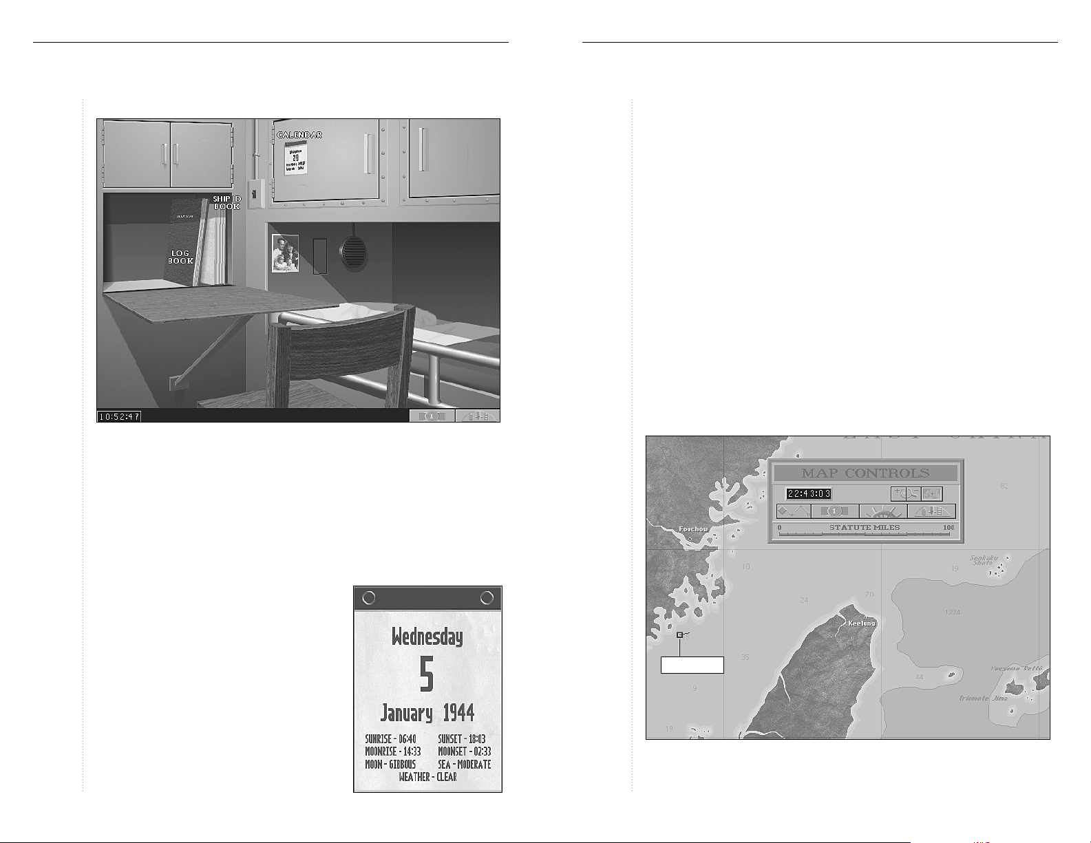
Captain’s Cabin
Ship Identification Manual
The Ship Identification Manual on the captain’s bookshelf is a valuable tool in
prosecuting the war against the enemy and not our own shipping. The Ship
Identification Manual contains views of thirteen classes of enemy vessels at
various angles. The displacement, length and maximum speed in knots are
also listed. A copy of this manual is available on the bridge to be used with the
Target Bearing Transmitter (TBT) and at the periscope.
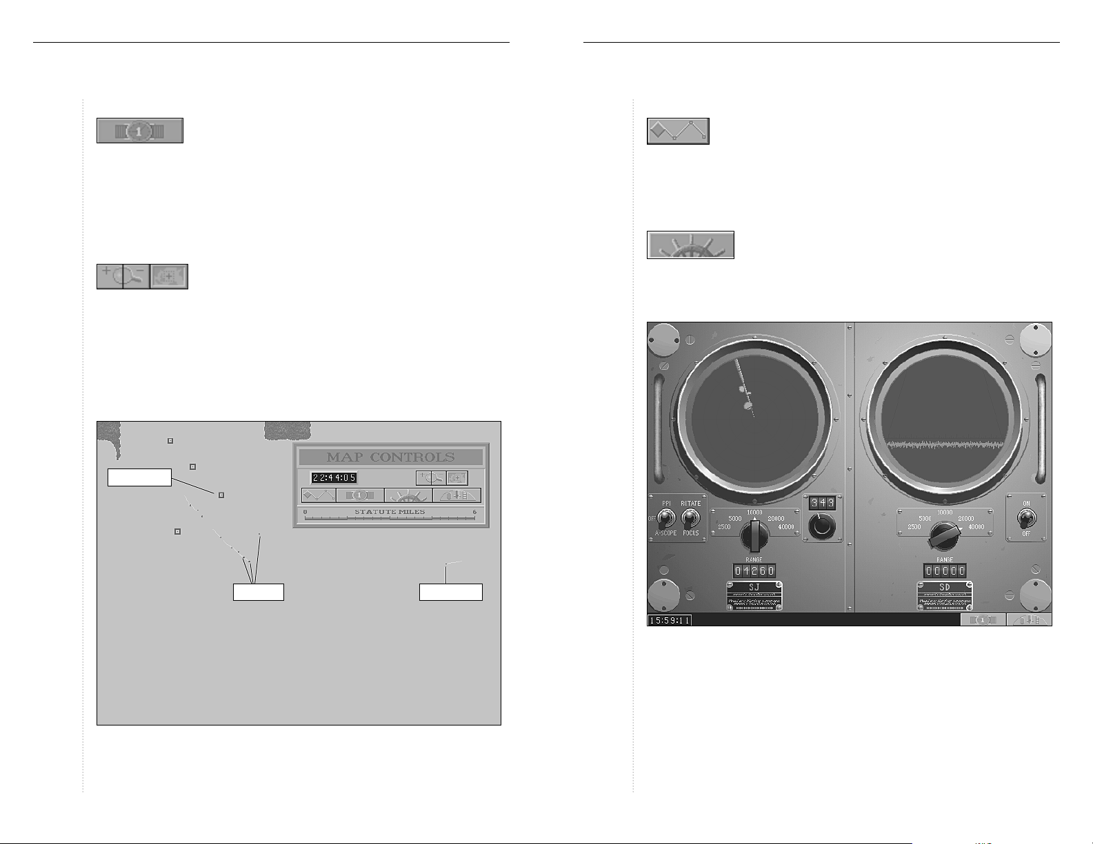
Charts
The Charts station is reached by pressing F5, or moving the pointer until it
reads Charts. The Charts station contains charts of the current patrol area,
showing important features such as depth information, enemy bases, shipping lanes, and ports of call. Visible enemy ships and reports of enemy
vessels are indicated on the chart for tracking purposes depending on the
realism level. Boxes that are available while viewing the charts allow for
maneuvering, setting way points along a course and general map controls.
At high levels of zoom the submarine is represented by a blue box trailing a
line away from its heading.
Sonar
At lower speeds the submarine’s sonar can detect other vessels. This is indicated on the map by a line along the relative bearing of the target. The line
is either gray, representing a set of low-speed screws, or orange, representing high-speed screws. High-speed screws are usually warships, while
low-speed screws can be either a merchant ship of some sort, or a warship
travelling at low speed.
Map Controls
Logbook
The Logbook can be viewed in the Captain’s
Cabin or by pressing F10. This is where the
crew’s victories are recorded as enemy shipping is harried across the Pacific.
Calendar
Left-clicking here shows more than the current date. Weather information, the phase of
the moon, and rising and setting times for the
sun and moon are also listed here.
Player Submarine
Page 11
SILENT
HUNTER
19 COMMANDING THE SUBMARINE: Charts
SILENT
HUNTER
20 COMMANDING THE SUBMARINE: Charts
Time Controls
The local time is displayed above the Time Compression
control button, and at the bottom left at most other stations. Activating Time Compression allows the rate time passes to be changed
from 1x to 256x. At 1x time passes at the normal rate. The + key increases com-
pression, while the –key decreases time compression. The Enterkey returns
the time rate to 1x. Note:Because of the complexity of this simulation, some
features may not operate smoothly at high rates of time compression.
Zoom and Centering Buttons
The Zoom controls allow a bird’s-eye view of the submarine
and other ships at the highest levels of magnification.
Zoom in by left-clicking on the “+” button, which turns the pointer into a
frame. Drag the frame over the section of the map to be viewed. At this
point, pressing the “Z” key increases the level of zoom, represented by the
size of the frame shrinking. Pressing the “X” key will increase the size of the
frame, decreasing the amount of zoom. Left-clicking a second time engages
the zoom and changes the view. At zoom levels below a certain point, some
map features such as depth gradients are not visible.
Reported Contact
Way Point Selection
The Way Point Selection button allows navigational way-points
to be set or cleared. Left-clicking on the map establishes a
course for the submarine which is followed until cleared from this panel by
pressing the CLEARbutton, when the course is completed, or if the manual
helm is used to override it.
Navigation
The Navigation button opens a box showing the Engine
Room Telegraph, the Manual Helm, the Speed Gauge,
Course Indicator and the Depth Control. The two buttons at the bottom
return to the Map Controls or the Control Room. For more information on
these controls see the “Gauges Station” section on page 23.
Visible Ships
Moving the cursor to the edge of the screen allows the entire map screen to
be shifted in any direction. The Centering button returns the submarine to
the center of the screen.
Player Submarine
Radar
The Radar station contains two radar range finding panels. On the left is
the SJ surface radar, on the right is the SD aerial radar. Both types of
radar can be tuned using the range knob; the scope will show an approximate representation of the distance to the target object, the digital readout
below the knob gives more precise range information. Note: Neither will
function if the submarine is below 45 feet.
Page 12
SILENT
HUNTER
21 COMMANDING THE SUBMARINE: Radar
SJ Radar
SJ surface search radar was installed on all submarines built after the war
started, and six of the older S-class submarines were refitted in 1943. Radar
made night surface-actions practical for submarines by generating accurate
range information.
SILENT
HUNTER
22 COMMANDING THE SUBMARINE: Torpedo Data Computer
The SJ radar represented in S
Plan-Position Indicator (PPI) and A-scope.
The PPI screen shows the direction the radar’s antenna is pointing with a
line that sweeps through 360 degrees. When a contact is made, the radar
produces a blip on the screen. Distance to the contact is indicated on the
digital readout below the central knob, and by the blip’s relative position on
the radar screen.
An A-scope contact doesn’t show the direction on the radar screen the way
the PPI does. The direction can be derived by the digital bearing readout on
the right side of the SJ console. A contact is represented as a spike in the
baseline reception, the size of the spike representing the size of the contact.
Contact range is indicated on the digital readout and by where the spike
appears on the screen. The farther to the left the spike appears, the closer
to the submarine the contact is.
The antenna can be aimed by switching from Rotate mode to Focus. This
allows the PPI scope to be aimed by left-clicking right on the scope screen
or by left-clicking the bearing knob. The A-scope is aimed using the bearing
knob on the SJ panel. The radar’s aim can be fine tuned by left-clicking on
the digital display above the knob to adjust the bearing of the antenna by
hundreds, tens, or single degrees. The SJ radar can be toggled on or off
using Alt-S. Left-clicking on the Range knob allows the radar coverage to
be fine tuned by aiming the radar at the bearing chosen.
ILENTHUNTER
can operate in two modes:
SD Radar
All submarines used in WWII were equipped with SD radar to prevent them
from being attacked by aircraft. The SD radar in S
scope variety, which reveals distance but not direction of aircraft detected
on the screen. A contact is represented as a spike in the baseline reception.
The SD radar can be toggled on or off using Alt-A.
ILENTHUNTER
is of the A-
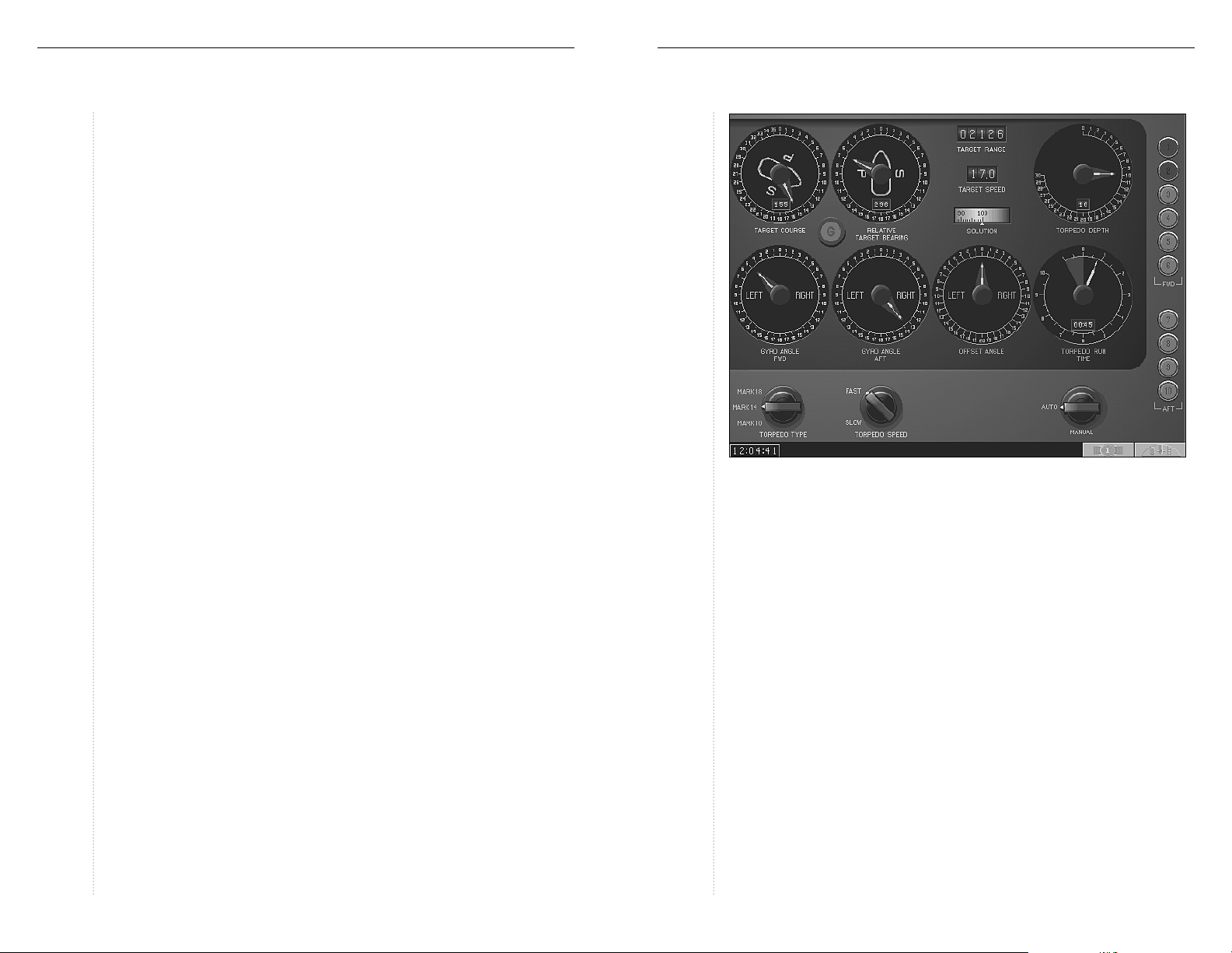
TDC (Torpedo Data Computer)
The controls on the Torpedo Data Computer (TDC) were remarkably
sophisticated for the period. The firing officer input the estimated speed
and course of the target ship, and the TDC compared this information with
the sub’s course and bearing and fed this information to the gyroscope in
the torpedo. Once fired, the torpedo ran straight for roughly 20 yards, then
altered course based on the gyro setting to intercept the target vessel.
There are three ways to access the TDC:
♦
At the main TDC station in the control room (or by pressing F6).
♦
Using the TBT binocular mount on the Bridge.
♦
Through the periscope.
The main TDC station has the complete set of controls and indicators for
setting and firing torpedoes, however there is no way to take a bearing on
the target from the TDC itself. The Target Bearing Transmitter (TBT) and
periscope TDC controls are split into three partial screens which are
accessed using a control knob. The launch buttons are arrayed on the right
side of the TDC, forward tubes on top, aft tubes below.
Page 13
SILENT
HUNTER
23 COMMANDING THE SUBMARINE: Torpedo Data Computer
SILENT
HUNTER
24 COMMANDING THE SUBMARINE: Gauges Station
Most torpedo attacks will be launched from the periscope in the control room or
the Target Bearing Transmitter on the bridge. See the “Using the Local TDC”
section on page 29 for information on using the TDC for making an attack.
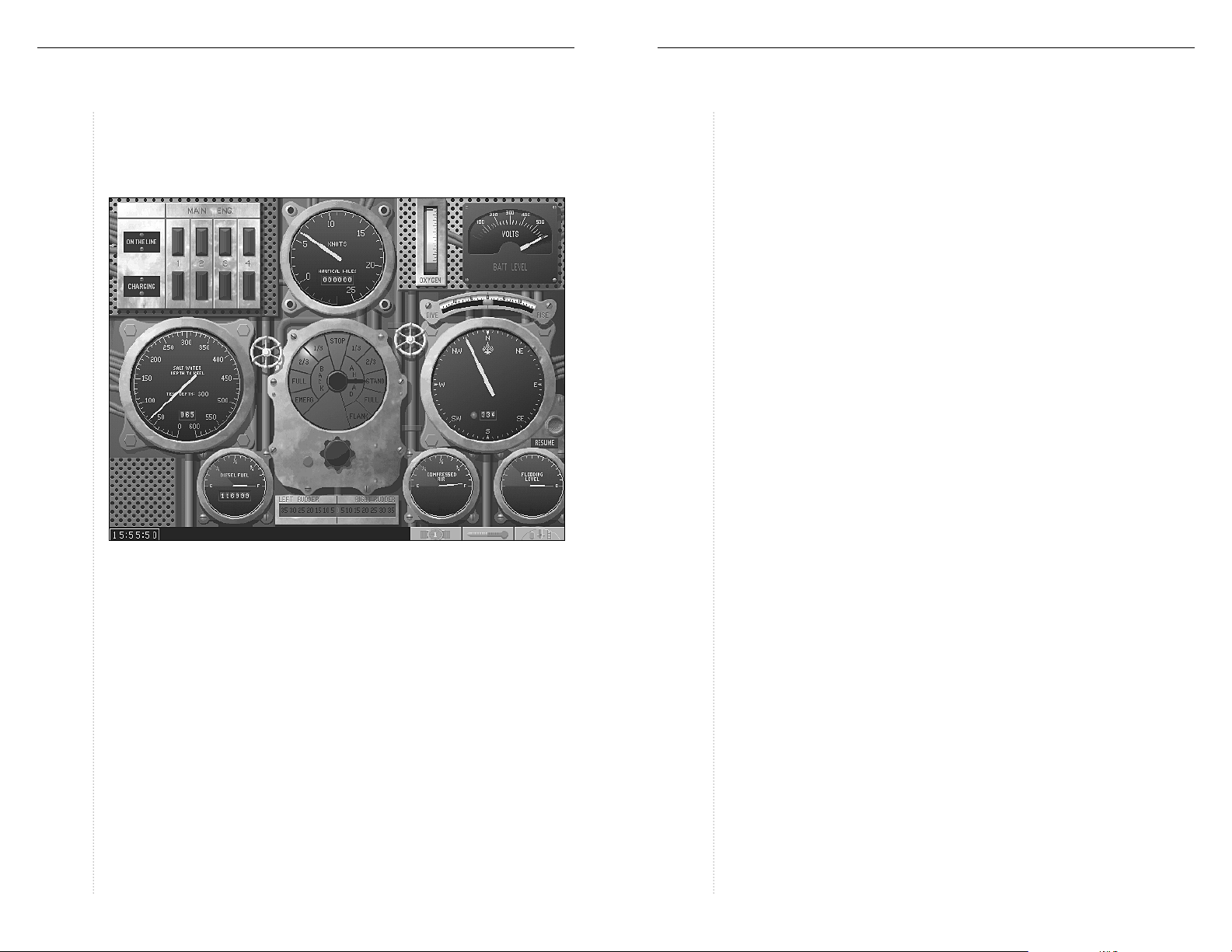
Gauges Station
In S
ILENTHUNTER
station and consist of the depth gauge, the compass, the manual helm, the
engine-room telegraph and the speed gauge. This station can also be
reached from anywhere on the submarine by pressing F7. There are also
displays for the electric motors, battery charge status, as well as gauges
showing the amount of compressed air, the level of flooding, the amount of
oxygen remaining, the remaining diesel fuel and the dive angle. The buttons in the lower right corner open the Time Compression box, toggle the
Bathythermograph, or return to the Control Room.
Maneuvering the submarine was the job of the diving officer, under the
command of the captain or the executive officer. Most submerged
maneuvering was done by dead reckoning using navigational fixes taken
while on the surface. The sub’s speed and course were tracked on navigational charts, which were the only means of determining the submarine’s
, the primary maneuver controls are found at the Gauges
position. Strong ocean currents, inaccurate charts and long periods operating
submerged without fixes created the possibility of running aground, particularly in the shallow seas of the Solomon, Marshall, and Philippine Islands.
Manual Helm
The submarine can be turned to port or starboard by left-clicking on the
Manual Helm, or pressing the left- or right-arrow key on the keyboard.
The 0 setting indicates a straight ahead course, barring wind and current.
Turns of up to 35degrees may be made to port or starboard by left-clicking
over that number on the Helm. The submarine continues to turn until the
Helm is returned to the 0setting, either by left-clicking on the 0or by pressing the arrow key which is opposite the current direction of turn until the
Helm reads 0; in other words, if left rudder is being applied, press the right
arrow key until the helm returns to 0. Pressing the “H” key establishes the
current heading as the new course and returns the Manual Helm setting to 0.
Pressing the “V” key restores the view to directly ahead of the submarine.
Compass
The course of the submarine can also be controlled using the compass. The
white needle indicates current course while the red needle indicates the
desired course. Left-clicking on the compass lays in a course, and the helm
responds by gradually turning the ship onto that course. The manual helm
should be used for radical course changes, such as evasive maneuvers or
attack maneuvers. A course laid-in previously can be returned to by leftclicking on the Resume button or by left-clicking on the compass.
Diving Controls
In S
ILENTHUNTER
depth on the depth-gauge or using a convenient keyboard command. The
dive angle is displayed on the inclinometer. Below 65 feet, the periscope
automatically retracts. Diving and surfacing are controlled by the diving
officer at the captain’s direction.
Diving involves the release of gas from the ballast tanks to reduce the submarine’s buoyancy to a point where the weight of the vessel overcomes the
displacement of water. As the submarine becomes less buoyant, the dive is
controlled using the bow planes and the electric motors. Surfacing is the
opposite of diving; compressed air is forced into the ballast tanks to replace
water taken on when diving. This creates a positive buoyancy, causing the
submarine to rise slowly. The bow planes and motors are used to control
diving and surfacing is handled simply by setting the dive
Page 14

SILENT
HUNTER
25 COMMANDING THE SUBMARINE: Gauges Station
SILENT
HUNTER
26 COMMANDING THE SUBMARINE: Gauges Station
the rate of change in depth. Once under water, with a neutral buoyancy,
the submarine maneuvers to different depths using the bow planes and
motors exclusively unless an emergency occurs where depth must be
gained or lost quickly. The diving planes can be controlled manually using
the “down” arrow key to cause the submarine to dive, the “up” arrow key to
cause a submerged submarine to climb, and the “5” key on the number
keypad to resume a straight and level course
The following keyboard equivalents exist for certain standard maneuvers to
simplify the process of changing depth:
♦
B – Blow tanks; emergency surface at maximum speed using your compressed air reserves in an inefficient manner Note: Using this command
leaves the submarine on the surface with few options since it takes time
to restore the compressed air.
♦
C – Crash dive; the submarine heads for 200 feet at maximum speed and
dive angle.
♦
P – Takes the submarine to periscope depth (65 feet).
♦
R – Takes the submarine to radar depth (45 feet).
♦
S – Surface normally.
Compressed Air Gauge
The number of times the submarine can change depth is dependent on the
supply of compressed air used to force water out of the ballast tanks. This
gauge indicates the amount of compressed air remaining. It is important to
be aware of the status of the submarine’s compressed air supply because
without compressed air the only way to change depth is by using the diving
planes and the electric motors. Once these tanks are empty, they can only
be recharged by sailing on the surface. This process takes an hour or two
depending on the amount of air required. If the submarine finds itself on
the bottom with no compressed air, returning to the surface may be an
impossible feat.
Thermal Layers and the Bathythermograph
In any large body of water, there are layers
where the water is warmer or cooler. The
bathythermograph plots water temperature
against depth to identify the location of these
thermal layers. The benefit of this is that
these layers reflect sound waves, which travel
very well through water, making it more difficult to locate a submarine using hydrophones or sonar. A submarine
beneath the thermal layer becomes nearly undetectable.
As the submarine descends, the bathythermograph indicates the temperature at every depth. When the bathythermograph indicates that the
temperature has dropped, this indicates that a thermal layer exists at that
depth. Diving below one of these layers is a good way to escape an enemy
ASW vessel.
Engine-Room Telegraph and Speed Gauge
Control of the submarine’s diesel engines and electric motors is performed in
the engine room. The Captain of the submarine forwards his orders by way of
the engine-room telegraph. The telegraph’s settings indicate the amount of
thrust the engines and motors are set to provide, either forward or reverse.
The speed of the submarine is indicated on the speed gauge and varies based
on sea conditions, damage, and whether the submarine is running submerged
or on the surface. Except at very low speeds, there is no way to come to a rapid
stop. Inertia causes the submarine to continue moving until the drag of the
water causes it to slow to a stop, unless reverse thrust is employed. The number keys across the top of the keyboard can also be used to control speed:
KEY TELEGRAPH SETTING
0...................................... All Stop
1...................................... Ahead 1/3
2...................................... Ahead 2/3
3...................................... Ahead Standard
4...................................... Ahead Full
5...................................... Ahead Flank
6...................................... Reverse 1/3
7...................................... Reverse 2/3
8...................................... Reverse Full
9...................................... Emergency Reverse
Page 15

SILENT
HUNTER
27 COMMANDING THE SUBMARINE: Gauges Station
Engine Status Indicator
The “Christmas tree,” so named for the red and green lights it features,
indicates which of the diesel engines are engaged in propelling the submarine or charging the batteries used to drive the electric motors. The panel
contains one green light and one red light for each engine on the submarine. When a diesel engine is being used to charge batteries the red light is
on, when the engine is being used to drive the submarine the corresponding green light is lit.
Voltage and Fuel Gauges
The state of battery charge is shown on the voltage gauge. When the electric motors are on line, the voltage level drops as batteries are discharged.
When the batteries are being charged using the diesel engines, one or more
of the red charging lights are lit and the needle climbs back to full charge.
It can take several hours running on the surface to recharge batteries. Most
of the submarines in S
low speed, but running at flank speed while submerged will exhaust battery
capacity quickly.
ILENTHUNTER
can run submerged for many hours at
SILENT
HUNTER
28 COMMANDING THE SUBMARINE: Up Scope
The fuel gauge shows the volume of diesel fuel remaining, with a digital
counter for the number of miles available from the remaining fuel. Note: The
amount of fuel carried by submarines was large enough to allow for extended
missions, but was not inexhaustible. If the submarine runs out of fuel, the
only margin of safety lies in the charge level on the batteries. If the submarine runs out of fuel in enemy waters, it is likely to be destroyed or captured.
Flooding Gauge
This gauge indicates the level of danger that flooding represents is in the
event that the submarine takes damage which ruptures the pressure hull so
that the submarine begins to take on water. The great danger of flooding is
that the submarine may gain so much weight that the motors cannot lift it
to the surface again.
Up Scope (or Periscope Station)
Left-clicking on the periscope shaft, or pressing F2, raises the periscope for
viewing the surface, navigation, or fire control. The periscope cannot be
employed at depths below 65 feet, and is automatically retracted when diving below that depth. The periscope also retracts automatically when
destroyed or damaged.
Moving the pointer to the handles on either side of the periscope activates
the Rotate Left or Rotate Right controls. Left-clicking when these commands
are visible, turns the periscope in the appropriate direction, through 360
degrees. At the top of the screen is the Relative Bearing Indicator, which
shows the bearing of any object viewed in the periscope relative to the submarine’s heading.
The right handle of the periscope is also used to control the zoom factor of
the periscope. When the pointer nears the right side of the periscope, it
changes to the Zoom command. Left-clicking while this command is active
increases the magnification through the settings 1x, 2x, 4x, and 8x.
Pressing the “Z” key achieves the same result. The periscope can be lowered
or raised from any station by pressing Alt-P.
When first activated, the periscope screen shows maneuver controls to
either side. These controls operate in the same manner as their counterparts at the Gauges station. The manual helm allows the submarine to be
steered, the course can be set using the compass, and the submarine can be
submerged or surfaced using the depth control. The Ship Identification
Manual can be viewed at this station using the button at the bottom of the
screen. Left-clicking on the Torpedo button or pressing the “T” key brings
up the Position Keeper panel for the local TDC.
Page 16

SILENT
HUNTER
29 COMMANDING THE SUBMARINE: Up Scope
SILENT
HUNTER
30 COMMANDING THE SUBMARINE: Up Scope
Using the Local TDC
The full TDC panel is not visible from the Periscope or the Target Bearing
Transmitter (TBT) stations, but has been divided into three separate panels
which appear to the right and left side of the Periscope and across the bottom
of the TBT. Some components of the TDC which do not change are the
Auto/Manual and Panel Selection switches and the firing buttons which are
just above the right handle of the periscope and at the far right of the TBT.
Pressing the “N” key restores the maneuver controls panel.
Left-clicking on the panel selection knob changes to the Angle Solver panel
which has the Gyro Angle Forward and Aft dials and Offset Angle dial. The
Offset Angle dial is used to establish a “spread” of torpedoes by locking a
course offset into each torpedo from the first torpedo fired. The Gyro Angle
Forward and Aft dials are primarily indicators unless the TDC is set to manual, when they become active for setting the offset from the submarine’s
heading that the torpedo will need to intercept the target.
For example, if the target is dead ahead, the relative target bearing would
be 0 degrees. The Relative Target Bearing dial shows an arrow pointing
straight up, aligned along the centerline of the submarine.
Calculating a firing solution is a very complex process. For more information
about the basic formulas of fire control, see Appendix C on page 73.
The Torpedo Depth setting dial and Torpedo Run Time dial are found on the
Torpedo Data panel, as are the Torpedo Speed knob and Torpedo Type knob.
The depth setting control is used to adjust the depth that torpedoes run.
Different classes of ship have a different draft, and a torpedo set to hit an aircraft carrier will pass harmlessly beneath a destroyer.
There is also a Torpedo Speed knob where the speed can be changed for
variable speed torpedoes. Common practice was to fire torpedoes at the
highest speed available unless the target is motionless. A slow torpedo is
more likely to be evaded by wary prey. The slow speed setting is useful
when shooting at stationary targets at long range, such as inside a shallow
harbor, where a close approach is too dangerous.
The panel that is visible the first time that a local TDC station is seen, is the
Position Keeper panel. It shows the Target Course and Relative Target
Bearing dials as well as the Target Range, Target Speed and Solution indicators. The Solution dial indicates the quality of any firing solution as a
percentage, from zero to one hundred percent. When a potential target is
visible in the eyepiece, a red arrow will flash beneath the target indicating
that the TDC is receiving information on that target. The longer a target is
in view, the more accurate a firing solution the TDC will provide. Locking
the target into the TDC allows the TBT or periscope to be used to view the
rest of the horizon, while the TDC continues to calculate. This is done
using the Mark button at the TBT station and the Spacebar at the Periscope.
Leaving the TBT or periscope station resets the TDC.
Making a Torpedo Attack
When using the TDC on automatic, the most important features to keep track
of are the target’s course, relative bearing, range, speed, and the firing solution quality. These are all located on the Position Keeper panel. All other
factors can be left to the game’s artificial intelligence (AI). The range indicator
is particularly important because a torpedo only arms itself after travelling 500
yards. The ideal range for torpedo launch at a moving target is between 500
and 1000 yards. Only targets that are at anchor or damaged should be shot at
from farther away than 1000 yards, particularly at higher levels of realism.
Once a target has been selected and locked into the TDC, the computer will
continue to calculate a firing solution. Making a successful torpedo attack
is a combination of having an accurate firing solution and being in range.
While the torpedoes used in U.S. submarines had maximum ranges of
between 3500 and 9000 yards, they were only used at ranges beyond 1500
yards in extreme situations.
Page 17

SILENT
HUNTER
31 COMMANDING THE SUBMARINE: Up Scope
Torpedoes can be fired by moving the mouse pointer over the illuminated
number buttons, which correspond to the torpedo tubes, and left-clicking
when the Fire reticule appears. When an appropriate range is reached,
between 500 and 1500 yards, and the Solution dial is reading an acceptable
level, preferably above 75%, fire away!
Torpedoes can also be fired by pressing the Alt key and the corresponding
torpedo tube number on the keyboard, so that pressing Alt-1 fires torpedo
tube one. The Alt-key combination is convenient because they can be used
to fire torpedoes from any station.
The Torpedo Run Time dial found on the Torpedo Data panel can be used
to monitor the time-to-target. Once torpedoes have been fired, escorts are
likely to attack the position the attack came from. Good tactical doctrine
suggests that keeping the periscope retracted until torpedo impact is imminent. Unlike the real world, submarines get credit for ships that sink,
whether anyone witnesses it or not.
Automatic vs. Manual
The Automatic/Manual knob determines whether the TDC continuously
feeds data into the torpedo gyroscopes or allows for manual correction of the
gyro setting. When set on automatic, the TDC automatically calculates a firing solution for whichever ship is being viewed through the periscope or
SILENT
HUNTER
32 COMMANDING THE SUBMARINE: Up Scope
Target Bearing Transmitter (TBT), as indicated by the flashing red arrow
below the target. Left-clicking on the Mark button on the TBT (or the Space
Bar when using the periscope) locks the current target into the TDC. At this
point, the red arrow below the target stops flashing and the TDC continues to
calculate a firing solution for that target even though it is not in view
through the scope. This allows the TDC to continue improving its firing solution while the viewing device is aimed elsewhere. This simulates the
continuous flow of information from periscope, radar, and hydrophones that
the submariners used to locate and destroy the enemy with.
Attempting to create a manual firing solution for torpedoes requires several
pieces of information about the target including the relative bearing, range,
course, and the speed. Without the continuous feed of information provided
by the TDC when on auto, the firing officer must make do with other sources.
The relative bearing, or angle on the bow, can be determined using the
periscope, TBT, or radar, if the submarine is equipped with it. The Officer
of the Deck will also call out the approximate bearing when contact is first
made. This information is programmed into the TDC using the Relative
Target Bearing dial. The mouse pointer will change to a reticule and the
word SET when moved over the dial. Simply left-click on the rim of the dial,
each increment represents 10 degrees, until the digital readout at the bottom of the dial is close enough to the desired bearing. The bearing of
targets can also be determined by the hydrophone operator when the submarine is travelling at low speed.
Determining range without the automatic setting will only be possible on
submarines equipped with radar. As a commander becomes more experienced, however, making range “guesstimates” will become easier. The
periscope has a set of graduated cross-hairs for that purpose. Once an estimated range is determined, move the mouse pointer over the Target Range
digital counter until the pointer becomes an upward pointing arrow. Leftclicking on a particular column increments the Target Range counter.
The target’s course should be entered in absolute terms; if the target is heading
due south, its course would be 180 on the compass. The easiest way to calculate this is by using the Ship Identification Book. If the target ship is facing the
submarine, start with a figure that is 180 degrees from the submarine’s course,
which can be found at any station with maneuver controls. Alter that number
to port or starboard based on the view angle as diagrammed in the Ship ID
Book. If the target ship is facing away from the submarine, the base course
starts similar to that of the submarine, which is then adjusted by the difference
in view. Adjust the Target Course dial in the same manner that the Relative
Target Bearing dial was adjusted, using the mouse pointer.
Page 18

SILENT
HUNTER
33 COMMANDING THE SUBMARINE: Up Scope
SILENT
HUNTER
34 COMMANDING THE SUBMARINE: Bridge
Speed is the most difficult to estimate. Once again, the Ship ID Book comes
into play. The general class of ship provides a reasonable estimate for the
target’s maximum speed. This information can be programmed into the
Target Speed counter in a similar manner to that of the Target Range. If all
else fails, target course and speed can be easily determined by switching the
TDC from manual to auto while the target is in view.
Once this information has been entered into the TDC, left-click on the red G
button in the center of the panel to generate a solution. When the G button is
illuminated, a solution is locked into the torpedoes. The Forward and Aft Gyro
Angle dials will present the gyro angle that is programmed into the torpedo.
These steps may need to be repeated until the solutions seems sufficiently
accurate. The Offset Angle dial is used at this point to establish a “spread” of
torpedoes by locking a course offset into each torpedo from the first torpedo
fired. Determining how wide a spread needs to be is a matter of experience, but
at ranges between 500 and 1000 yards, the offset should be from 5 to 10
degrees in order to get a sufficient amount of spread. At that point, fire the torpedoes! A distant booming sound in the hydrophones and an entry in the
submarine’s log will indicate the sinking of the enemy.
submarine while on the surface: the Depth Gauge, Compass, Manual Helm,
Engine-Room Telegraph and Speed Gauge. For information about giving
dive commands, see the “Diving Controls” section on page 24.
Compass
The course of the submarine can also be controlled using the compass. The
white needle indicates current course while the red needle indicates the
desired course. Left-clicking on the compass lays in a course, and the helm
responds by gradually turning the ship onto that course. The manual helm
should be used for radical course changes, such as evasive maneuvers or
attack maneuvers. A previously laid-in course can be returned to by left-clicking on the Resumebutton or by left-clicking on the compass.
Manual Helm
The submarine can be turned to port or starboard by left-clicking on the
Manual Helm, or pressing the left- or right-arrow key on the keyboard. The
0 setting indicates a straight ahead course, barring wind and current. Turns
of up to 35 degrees may be made to port or starboard by left-clicking over
that number on the Helm. The submarine continues to turn until the Helm
is returned to the 0 setting, either by left-clicking on the 0 or by pressing
the arrow key which is opposite the current direction of turn until the
Helm reads 0. Pressing the “H” key establishes the current heading as the
new course and returns the Manual Helm setting to 0. Pressing the “V” key
restores the view to directly ahead of the submarine.
Depth Gauge Compass
Relative Bearing
Engine Room Telegraph Speed Gauge
Manual Helm
Bridge
Climbing the ladder to the Bridge presents a 40-degree view of the surrounding waters. A set of maneuver controls is here for commanding the
Engine-Room Telegraph and Speed Gauge
Control of the submarine’s diesel engines is performed in the engine room. The commander of the submarine forwards his orders by way of the Engine-Room Telegraph.
The Telegraph’s settings indicate the amount of thrust the engines are set to provide,
either forward or reverse. The speed of the submarine is indicated on the Speed
Gauge and varies based on sea conditions, damage, and whether the submarine is
running submerged or on the surface. Except at very low speeds, there is no way to
come to a rapid stop. Inertia causes the submarine to continue moving until the drag
of the water causes it to slow to a stop, unless reverse thrust is employed. The number
strip across the top of the keyboard can also be used to control speed:
KEY TELEGRAPH SETTING KEY TELEGRAPH SETTING
0 . . . . All Stop 5.......... Ahead Flank
1 . . . . Ahead 1/3 6.......... Reverse 1/3
2 . . . . Ahead 2/3 7.......... Reverse 2/3
3 . . . . Ahead Standard 8.......... Reverse Full
4 . . . . Ahead Full 9.......... Emergency Reverse
Page 19

SILENT
HUNTER
35 COMMANDING THE SUBMARINE: Bridge
SILENT
HUNTER
36 COMMANDING THE SUBMARINE: Bridge
Moving the pointer to the far left or far right edges of the screen activates
the Rotate Left or Rotate Right controls. Left-clicking when these commands
are visible moves the view in the appropriate direction through 360
degrees. At the bottom of the screen, below the Manual Helm, is the
Relative Bearing Indicator which shows the bearing of any object centered
on the screen relative to the submarine’s heading.
Two other stations besides the Control Room can be reached from the
Bridge station, the Target Bearing Transmitter and the Deck Gun.
Moving the pointer to the grips on either side of the TBT activates the Rotate
Left or Rotate Right controls. Left-clicking when these commands are visible,
turns the periscope in the appropriate direction, through 360 degrees. Above
the eyepiece of the TBT is the Relative Bearing Indicator, which shows the
bearing of any object viewed in the TBT relative to the submarine’s heading.
The Zoom can be increased by left-clicking on the lever to the upper-right of
the zoom level readout on the right side of the TBT. On the top of the left
handle is the Markbutton which is used to lock targets into the TDC.
Other than the placement of dials on the three TDC panels, the use of the
TDC from the TBT station is exactly the same as from the periscope. For
more information about using the local TDC, see the “Using the Local
TDC” section on page 29.
Target Bearing Transmitter (TBT)
Left-clicking on the button with the binoculars on it changes to the Target
Bearing Transmitter (TBT) station. This station can also be reached from anywhere on the submarine by pressing F3. When first entered, the lower half of
the TBT screen contains a set of helm controls: Depth Control, Compass,
Engine Room Telegraph and Manual Helm. These controls operate exactly like
their counterparts at the Periscope station and the Gauges station. The Ship
Identification Manual can be viewed at this station using the button at the
bottom of the screen. Left-clicking on the Torpedo button or pressing “T”
brings up the Position Keeper panel for the local TDC. Pressing the “N” key
restores the navigation controls.
Deck Gun
Left-click on the Deck Gun button while on the Bridge to bring up the firing
controls of the deck gun. Pressing Alt-F4 from any location while surfaced
will also man the Deck Gun. Historically, deck guns were mainly used to finish off damaged ships rather than expend torpedoes. The odds of a submarine
winning a surface battle with a patrol boat or destroyer are very small. Some
classes of submarine carried two deck guns, such as the Tench class and the
Narwhal class. On these submarines, there is an additional Deck Gun button
with the letter ‘F’ for forward and ‘A’ for aft.
Page 20

SILENT
HUNTER
37 COMMANDING THE SUBMARINE: Bridge
The knob on the right side of the sighting scope raises and lowers the gun,
and the smaller knob on the left side of the sighting scope increases the
zoom from 1x to 2x, 4x, and 8x then back to 1x. Moving the pointer to the
handles on either side of the gun mount activates the Rotate Left or Rotate Right
controls. Left-clicking when these commands are visible turns the gun
mount in the appropriate direction, through 350 degrees. Note: the deck
gun cannot be trained on anything directly in front of the submarine since
that would force it to shoot through the conning tower. The same applies to
two mount submarines for the forward gun.
At the top of the screen is the Relative Bearing Indicator, which shows the
bearing of any object viewed in the sighting scope relative to the submarine’s heading. Below the sighting scope is the control panel for the deck
gun. The large black button on the left side of the panel fires the gun. The
knob above the target range display toggles control of the gun between
automatic and manual as does pressing Alt -G. When set on automatic, the
deck gun will fire at the nearest target until the gun is taken off of automatic, the submarine submerges, all the ammunition is used up, the
quality of aim drops below 80%, or the gun is damaged.
SILENT
HUNTER
38 COMMANDING THE SUBMARINE: Status and Torpedo Room Stations
The closer to the target, the more effective the deck gun can be. A red triangle
will appear in the sighting scope when the target has been acquired, and the solution dial shows the increasing solution quality. The solution dial indicates how
accurate the firing solution is for the deck gun. Speed, weather, and crew quality
all effect how accurate gunnery fire is. Press the fire button to fire the gun when
the target is centered in the cross-hairs of the sighting scope. The ready light
indicates the wait while the gun is reloaded and the shells counter shows the
amount of ammunition remaining.
Status and Torpedo Room Stations
Pressing F8 from any station, or moving the pointer until it changes to the
word Status while in the control room, shows the Damage Control and Status
station. The cut-away view of the submarine at the top of the screen contains
important areas of the submarine outlined in dark red. Damaged areas are
outlined in a brighter color red and may show some animation, for example,
flooding. When the cursor is over an area for which a damage report is available, it changes from an arrow to a cross-hair. Left-clicking causes the status
of that area to be shown on the Damage Control Report panel.
Below the cut-away are the display panels which show the status of important
ship systems. Each system has “Christmas tree” lights which allow a quick
status check of systems such as the torpedo tubes and specific engines.
If the submarine suffers damage, the Damage Control Report panel lists
important information about the damage. The location of the damage, the
severity of the damage, the repair status and time if repairs are possible,
and any effects the damage may be having on submarine operations.
Page 21

SILENT
HUNTER
39 COMMANDING THE SUBMARINE: Status and Torpedo Room Stations
Torpedo Room
There were three types of torpedoes available during the course of the war,
but not all submarines could carry all three types. Most of the submarines
built before the war, including the S-, Barracuda, and Narwhal classes,
were equipped to carry only the older Mark 10 torpedo. The later “fleet”
submarines, including the P-, Salmon, T-, Gato, Balao, and Tench classes
were equipped to carry the longer Mark 14 torpedoes. They could also
accommodate the Mark 10 and the Mark 18 electric torpedo when it
became available in 1944.
Left-clicking on the torpedo button on the Status Station screen shows
the contents of the forward and aft torpedo rooms. The submarines in
S
ILENTHUNTER
those loaded in the tubes. Once one or more torpedoes have been fired, the
reload process is automatic and is affected by the Realism setting chosen,
the crew quality level chosen, and any damage the submarine has sustained. Once the reloading process is under way, the time remaining until a
tube is reloaded can be determined by left-clicking over that tube.
carry between twelve and twenty-eight torpedoes including
SILENT
HUNTER
40 SUBMARINES
SUBMARINES
The submarines that were used in the desperate battles above and below
the waves of the Pacific included some which were the epitome of modern
technology and design. Others that saw duty were older, slower, more
cramped but contained crews whose bravery and dedication could not have
been overmatched by mere technology. Despite the brutal lessons taught
during World War I by the Kaiser’s U-boat wolfpacks, the development of
submarine technology held a position of secondary importance to that of
the battleship, aircraft carrier and cruiser. Changes were in progress at the
war’s beginning, but both the Pacific command, SubPac, and the Asiatic
fleet, still had antiquated S-class submarines.
Note: Torpedoes from the forward torpedo room cannot be moved aft
except while in port.
Page 22

SILENT
HUNTER
41 SUBMARINES: S-Class
SILENT
HUNTER
42 SUBMARINES: Barracuda
♦
S-Class
Displacement (in tons): . . . . 903 when surfaced; 1230 when submerged
Dimensions (in feet): . . . . . .265 x 21 x 13
Machinery: . . . . . . . . . . . . . . 2 diesel engines; 2 electric motors
Max. Power (in hp): . . . . . . . 1800 surfaced; 1500 submerged
Max. Speed (in knots): . . . . . 14.5 surfaced, 11 submerged
Test Depth (in feet): . . . . . . .200
Range (in miles): . . . . . . . . .8000 at 10 knots surfaced
Torpedo Tubes: . . . . . . . . . . 4 forward; 1 aft; 12 torpedoes
Guns: . . . . . . . . . . . . . . . . . .1 – 4 inch
The oldest U.S. submarines to see combat in World War II were the S-class,
some of which had been launched as early as 1918. Six “sugar boats” were
stationed at Manila with the Asiatic Fleet and six with the Pacific Fleet at
Pearl Harbor. These submarines accounted for fourteen Japanese ships
including the destroyer Natsushio sunk by S-37 in February 1942 and the
cruiser Kako sunk by S-44 in August 1942.
Designed and built during the first World War, S-class submarines were
designed for a defensive role, to interdict other submarines along the
Atlantic coastline. When compared with the later fleet-type submarines,
they were more cramped, smaller, and had a shorter range. They featured
double hull construction with the ballast tanks on the outside of the pressure hull. The hulls were riveted together, as were most ships constructed
prior to the war. Underwater speed was deemed an important feature at the
time of their design, to enable the submarine to evade escorts. Speed was
sacrificed later for more dependable surface performance and safety features such as an enclosed bridge.
♦
Barracuda
Displacement (in tons): . . . . 2000 when surfaced; 2620 when submerged
Dimensions (in feet): . . . . . .341 x 27 x 14
Machinery: . . . . . . . . . . . . . . 2 diesel engines; 2 electric motors
Max. Power (in hp): . . . . . . . 6700 surfaced; 2400 submerged
Max. Speed (in knots): . . . . . 18 surfaced, 8 submerged
Test Depth (in feet): . . . . . . .200
Range (in miles): . . . . . . . . .12000 at 11 knots surfaced
Torpedo Tubes: . . . . . . . . . . 4 forward; 2 aft; 12 torpedoes
Guns: . . . . . . . . . . . . . . . . . .1 – 5 inch
The Barracuda class were an early attempt at what would later be called the
fleet-class submarine. They were not as fast as the S-class when submerged,
but were larger and capable of longer patrols. None of the B-class submarines, Barracuda, Bass, or Bonita saw service during the war, except as
training vessels.
Page 23

SILENT
HUNTER
43 SUBMARINES: Narwhal
SILENT
HUNTER
44 SUBMARINES: P-Class
♦
Narwhal
Displacement (in tons): . . . . 2915 when surfaced; 4050 when submerged
Dimensions (in feet): . . . . . .371 x 33 x 15
Machinery: . . . . . . . . . . . . . . 1 diesel engines; 2 electric motors
Max. Power (in hp): . . . . . . . 6000 surfaced; 2450 submerged
Max. Speed (in knots): . . . . . 17 surfaced, 8 submerged
Test Depth (in feet): . . . . . . .328
Range (in miles): . . . . . . . . .18000 at 8 knots surfaced
Torpedo Tubes: . . . . . . . . . . 4 forward; 2 aft; 26 torpedoes
Guns: . . . . . . . . . . . . . . . . . .2 – 6 inch
The Narwhal and Nautilus were submarine cruisers, large enough to
accommodate two 6-inch deck guns and capable of higher surface speeds
than the older S-class. They were derived from an earlier mine-laying
design, the Argonaut. In practice, the greater size needed to accommodate
the second deck gun made the submarine easier to detect and did not make
up for poor handling characteristics. The original diesel engines never delivered horsepower adequate to the task of maneuvering such a large vessel
and were replaced in 1940. Both submarines were used to deliver supplies to
guerrillas, transport commandos and coast watchers. Between them, they
managed to sink eleven Japanese ships including the destroyer Yamakaze.
♦
P-Class
Displacement (in tons): . . . . 1330 when surfaced; 2005 when submerged
Dimensions (in feet): . . . . . .300 x 25 x 13
Machinery: . . . . . . . . . . . . . . 2 diesel engines; 2 electric motors
Max. Power (in hp): . . . . . . . 4300 surfaced; 2336 submerged
Max. Speed (in knots): . . . . . 19 surfaced, 8 submerged
Test Depth (in feet): . . . . . . .250
Range (in miles): . . . . . . . . .10000 at 10 knots surfaced
Torpedo Tubes: . . . . . . . . . . 4 forward; 2 aft; 16 torpedoes
Guns: . . . . . . . . . . . . . . . . . .1 – 4 inch
P-class submarines, represented by the Pike, Pickerel, and Permit, were the
earliest pre-cursor to the Gato class. They were innovative in that they were
welded rather than riveted, had air-conditioning, and used diesel engines to
drive generators which powered electric motors. This allowed the submarine to cruise on the surface with one engine while using the other to
charge the batteries used during submerged operation.
Welded construction permitted the submarines to dive deeper and withstand attacks from depth charges better. Most of the subs in this class were
divided into nine watertight compartments. A few had additional external
torpedo tubes added fore and aft to increase their firepower.
Page 24

SILENT
HUNTER
45 SUBMARINES: Salmon
SILENT
HUNTER
46 SUBMARINES: T-Class
♦
Salmon
Displacement (in tons): . . . . 1449 when surfaced; 2198 when submerged
Dimensions (in feet): . . . . . .310 x 27 x 14
Machinery: . . . . . . . . . . . . . . 2 diesel engines; 2 electric motors
Max. Power (in hp): . . . . . . . 5500 surfaced; 3300 submerged
Max. Speed (in knots): . . . . . 20 surfaced, 9 submerged
Test Depth (in feet): . . . . . . .256
Range (in miles): . . . . . . . . .10000 at 10 knots surfaced
85 at 5 knots submerged
Torpedo Tubes: . . . . . . . . . . 4 forward; 4 aft; 20 torpedoes
Guns: . . . . . . . . . . . . . . . . . .1 – 4 inch
The Salmon class consisted of six submarines which were nearly identical
to the ten submarines of the Sargo class. Both types had been increased in
length by ten feet and had their battery capacity substantially increased for
a submerged cruising range of 80 miles or more. Two additional rear-firing
tubes brought the total up to eight, and the overall torpedo capacity was
increased to 20.
The vessels of these classes had one dangerous problem early in their history in the form of a faulty hatch covering the main diesel induction. This
caused the loss of Squalus and twenty-three crew members in 1939, and
both Snapper and Sturgeon experienced similar, though not fatal, failures
of the induction hatch during the war.
♦
T-Class
Displacement (in tons): . . . . 1475 when surfaced; 2370 when submerged
Dimensions (in feet): . . . . . .307 x 27 x 14
Machinery: . . . . . . . . . . . . . . 2 diesel engines; 2 electric motors
Max. Power (in hp): . . . . . . . 5400 surfaced; 2740 submerged
Max. Speed (in knots): . . . . . 20 surfaced, 8.75 submerged
Test Depth (in feet): . . . . . . .200
Range (in miles): . . . . . . . . .8000 at 10 knots surfaced
60 at 5 knots submerged
Torpedo Tubes: . . . . . . . . . . 6 forward; 4 aft; 24 torpedoes
Guns: . . . . . . . . . . . . . . . . . .1 – 5 inch
An increase in displacement of fifteen tons added two torpedoes in front
and increased the total number of torpedoes carried to 24. The vessels in
the T-class had the distinction of being the last peace-time submarines
commissioned, and were thus forced to carry the load for the Navy during
the opening months of the war until the Gato class submarines arrived
later in 1942. The crew complement was 60.
The highest scoring submarine of the Pacific campaign in number of vessels sunk was the Tautog, a T-class submarine, with 26 confirmed sinkings.
Page 25

SILENT
HUNTER
47 SUBMARINES: Gato
SILENT
HUNTER
48 SUBMARINES: Balao
♦
Gato
Displacement (in tons): . . . . 1825 when surfaced; 2410 when submerged
Dimensions (in feet): . . . . . .312 x 27 x 15
Machinery: . . . . . . . . . . . . . . 4 diesel engines; 4 electric motors
Max. Power (in hp): . . . . . . . 5400 surfaced; 2740 submerged
Max. Speed (in knots): . . . . . 20.75 surfaced, 8.75 submerged
Test Depth (in feet): . . . . . . .300
Range (in miles): . . . . . . . . .11800 at 10 knots surfaced
95 at 5 knots submerged
Torpedo Tubes: . . . . . . . . . . 6 forward; 4 aft; 24 torpedoes
Guns: . . . . . . . . . . . . . . . . . .1 – 4 inch
The Gato, Balao (pronounced ba-ley’-o), and Tench classes were virtually
identical and formed the backbone of the U.S. submarine force from late
1942 through the end of the war. The fundamental “fleet” submarine, they
were all of welded construction and capable of operating at greater depths
than their predecessors— they had crush depths of up to 750 feet which
allowed operation at depths of between 300 and 400 feet. The displacement
of these fleet class submarines was increased again to more than 1800 tons
to accommodate even more batteries and improved diesel engines. The
crew complement for a war patrol was 80 officers and crewmen.
One hundred and eighty five submarines of these three classes saw war
service; 73 Gato, 101 Balao, and 11 Tench. Of the twenty highest scoring
submarines in both tonnage and number of ships sunk, two thirds were
either Gato or Balao class. The top three submarines in terms of tonnage
sunk were all Gato class, the Flasher, the Rasher and the Barb with nearly
300,000 tons sunk between them. The Skate, which was commanded by
Bud Gruner was a Balao class.
♦
Balao
Displacement (in tons): . . . . 1826 when surfaced; 2391 when submerged
Dimensions (in feet): . . . . . .312 x 27 x 15
Machinery: . . . . . . . . . . . . . . 4 diesel engines; 4 electric motors
Max. Power (in hp): . . . . . . . 5400 surfaced; 2740 submerged
Max. Speed (in knots): . . . . . 20.75 surfaced, 8.75 submerged
Test Depth (in feet): . . . . . . .400
Range (in miles): . . . . . . . . .11800 at 10 knots surfaced
95 at 5 knots submerged
Torpedo Tubes: . . . . . . . . . . 6 forward; 4 aft; 24 torpedoes
Guns: . . . . . . . . . . . . . . . . . .1 – 5 inch
See Gato, page 47.
Page 26

SILENT
HUNTER
49 SUBMARINES: Tench
♦
Tench
Displacement (in tons): . . . . 1860 when surfaced; 2428 when submerged
Dimensions (in feet): . . . . . .312 x 27 x 15
Machinery: . . . . . . . . . . . . . . 4 diesel engines; 4 electric motors
Max. Power (in hp): . . . . . . . 5400 surfaced; 2740 submerged
Max. Speed (in knots): . . . . . 20.75 surfaced, 8.75 submerged
Test Depth (in feet): . . . . . . .400
Range (in miles): . . . . . . . . .12000 at 10 knots surfaced
95 at 5 knots submerged
Torpedo Tubes: . . . . . . . . . . 6 forward; 4 aft; 28 torpedoes
Guns: . . . . . . . . . . . . . . . . . .2 – 5 inch
See Gato, page 47.
SILENT
HUNTER
50 SILENT HUNTER WEAPONS DATA
SILENT HUNTER WEAPONS DATA
U.S. Torpedoes
MODEL ENGINE MAX. SPEED MAX. RANGE WARHEAD WT
Mk 10 Turbine 36 Kts 13,500 yds 385 Lb. 1917-1943
Mk 14 Turbine 46 Kts 9,000 yds 507 Lb. 1939-1945
Mk 18-1 Electric 27 Kts 4,000 yds 500 Lb. Oct. 1943
Mk 18-2 Electric 40 Kts 4,000 yds 500 Lb. Aug. 1944
.
DATE
Radar and Bathythermograph
NAME USE RANGE AVAILABLE
SD Air 6-10 miles Jan. 1942
SJ Surface Aug. 1942
Imp. SJ Surface Dec. 1942
A-Scope Surface Dec. 1941
PPI Surface Sept. 1943
APR-1 Radar Detector Surface May 1944
Bathythermograph Submerged Thermal Layers Mar. 1943
Deck Guns/AA Guns
TYPE USE AVAILABLE
.50 Cal. MG AA 1938 Some subs also had 2 or 3 .30 Cal. MG’s as well
20mm AA 11/42
40mm AA 4/44 Note: By late 1944 most subs mounted both
3in/50 Gun Surface 1938
5in/25 Gun Surface 8/44 Smaller version of the 5in/51, some subs
5in/51 Surface 7/42 Standard 5in gun for most sub classes.
20mm & 40mm AA guns.
mounted 2 of these guns by 1945.
TORPEDOES
Shortages
Many problems faced by the Pacific submariners had nothing to do with
tropical storms, the sweltering heat of tropical waters, or the actions of
hostile escorts and aircraft. Frequently, torpedoes were seen to explode
near or heard to hit targets, but later investigation indicated that they had
exploded prematurely or been duds. Shortages of torpedoes in the early
months of the war meant that submarine commanders had to carefully
hoard their torpedoes, and could not always fire on targets of opportunity.
Page 27

SILENT
HUNTER
51 TORPEDOES: Shortages
SILENT
HUNTER
52 TORPEDOES: Torpedo Types
The primary torpedo storage facility at Pearl Harbor endured the bombing
on 7 December 1941 largely unscathed. Unfortunately, 233 torpedoes were
destroyed by the 10 December bombing of Cavite Navy Yard in the
Philippines. Torpedo production at the war’s start was roughly 60 per month
from the torpedo manufacturing facilities at Newport, Rhode Island and
Alexandria, Virginia and reserves were only in the hundreds. Transportation
difficulties continued to make supply a problem even after production had
overcome expenditure by early 1943.
Torpedo Types
Three primary types of torpedoes were carried by U.S. submarines: the
Mark 10, the Mark 14, and the Mark 18. Both the Mark 10 and Mark 14
were steam powered, 21 inches in diameter and used T.N.T. at the war’s
beginning, but were converted to torpex by war’s end. The Mark 10 was the
standard torpedo on the earlier S-boats, while the Mark 14 was used on the
later fleet submarines, which were designed to accommodate its length.
At the war’s start, the Mark 10 had been in service on the older S-boats for a
decade. The warhead of the Mark 10 carried 497 pounds of T.N.T. in 1941; later
it was converted to carry 485 pounds of torpex. Fitted with the Mark 3 contact
detonator, the Mark 10 had a range of 3500 yards at a speed of 36 knots.
The Mark 14 was the latest in U.S. torpedo technology in 1941. While still
21 inches in diameter, it had been designed to be superior in almost every
way. The Mark 14’s normal range had been increased to 4500 yards at a
speed of 46 knots, but was also capable of a greater range of 9000 yards at a
lower speed setting of 31.5 knots (although in practice this was rarely
used). The warhead held 507 pounds of T.N.T. when first issued, but was
later improved to carry a 668-pound torpex payload. The crucial difference
between the Mark 14 and its predecessor was the Mark 6 detonator.
Between the World Wars, the Mark 6 detonator was developed to take advantage of the magnetic field that ships created in the water around them.
Besides a contact detonator similar to that used in the Mark 3, the Mark 6
used a magnetic detonator. Designed to explode the warhead as the torpedo
passed through the target’s magnetic field, the magnetic detonator effectively
increased the target area. Conventional wisdom of the pre-war era held that
an explosion under the keel of the ship caused more damage because of the
presence of armor plating at the waterline and internal compartmentalization. In theory, the Mark 14 would be a difficult weapon to evade.
History proved differently. For the sake of secrecy and economy, test firings
by submarines used a dummy warhead or were set to pass beneath the target vessel. This was to avoid damaging the ship or torpedo and accustom
the crew to relying on the magnetic detonator. This methodology disguised
several very serious flaws in the Mark 14 torpedo and the Mark 6 detonator
that were only revealed as each prior problem was solved. A 1943 Bureau of
Ships report on the circumstances of shipping sunk by U-boats also disproved the keel damage theory. The report indicated that most damaged
ships that sank foundered from loss of stability rather than actual flooding.
Problems Arise
Submarines went to sea in 1941 and 1942 with a largely untried weapon, and
began reporting premature detonations and a number of missed shots. At
first, these problems were explained by the Bureau of Ordinance as “human
error.” The newly promoted Rear Admiral, Charles Lockwood made a priority
of getting to the bottom of the matter. After a number of reports of missed
shots, Admiral Lockwood had the submarines Skipjack and Saury test fire
Mark 14 torpedoes set for a depth of 10 feet at a net strung 850 yards away.
The first test, made by Skipjackon June 20, 1942 showed that torpedoes set
for 10 feet were punching through the net at depths between 18 and 25 feet.
Torpedoes set for zero depth ran down to 11 feet too deep.
These first tests were rejected by the Bureau of Ordinance, so a second set
of test shots were made by Saury on July 18. The results were the same.
Both Mark 10 and Mark 14 torpedoes would actually run as much as 10 feet
deeper than they were set. For the Mark 10 this was a serious problem,
since it actually needed to contact the enemy vessel to detonate.
Theoretically, this was less of a problem for the Mark 14, since the magnetic detonator should still cause an explosion when it entered the target’s
magnetic field. In practice this was not the case.
Detonator mechanisms were deactivated at the point of firing to prevent
them from exploding early while the torpedo “found its bearings.” The torpedo traveled for approximately 450 yards after firing before the safeties
released and allowed the detonator, which was itself a small bomb, into
contact with the normally inert explosive in the warhead. At this point, several mechanisms became active. Since a spread of torpedoes were fired
sequentially, they were equipped with a device to prevent the explosion of
one torpedo from triggering premature explosions in those nearby. This
anti-counter-mining device actually locked the magnetic exploder on some
deep-running torpedoes, preventing detonation.
Once the depth-setting problem was corrected, the next fault to appear was
the tendency to detonate prematurely. In this case, it was the magnetic detonator that was found to be largely at fault. If the torpedo were running
shallow, it would encounter the ship’s magnetic field far enough away from
Page 28

SILENT
HUNTER
53 TORPEDOES: Problems Arise
SILENT
HUNTER
54 TORPEDOES: The New Hope
the target to cause a premature explosion. Several commanders also reported
that torpedoes detonated shortly after arming. In July, 1943 Admiral Nimitz,
Commander in Chief, Pacific (CinCPac) ordered that all submarines and
destroyers under his command disable the magnetic component of the Mark
6 detonator. Other commands slowly followed suit, and by March of 1944, all
of the Mark 14 torpedoes were set for contact detonation only.
On 24 July 1943 the Gato class submarine Tinosa, skippered by Lieutenant
Commander L.R. Daspit had sixteen Mark 14 torpedoes aboard, when it
found the 19,200 ton tanker Tonan Maru No. 3.Forced to make a long
range shot at an oblique angle, the Tinosa nevertheless rendered the tanker
immobile with four torpedo hits. Unable to surface because of the Tonan
Maru’s deck guns, the Tinosa lined up a perfect 90 degree shot at an optimal
range of 875 yards. The first torpedo ran true, but failed to explode, as did a
second. After careful checks and aiming, Tinosa fired two more — neither
exploded. Lt. Commander Daspit fired seven of his remaining eight torpedoes at the helpless tanker, all of which struck home but failed to detonate.
After Lieutenant Commander Daspit’s incredible report, Admiral Lockwood
ordered tests performed at Pearl Harbor. These tests confirmed that the
contact exploder’s firing pin would release, but friction on guide pins
within the mechanism would prevent the firing pin from striking the
primer hard enough to go off. A simple correction was rapidly devised, and
Mark 14 torpedoes went into service that could be expected to run at the
depth set, not explode prematurely, but detonate on what they hit.
Perhaps the most peculiar thing about the various problems suffered by the
U.S. Navy with the Mark 14 torpedo and the Mark 6 detonator is that the
German Kriegsmarine had experienced a nearly identical series of problems.
Problems with depth keeping, the magnetic detonator, and the contact detonator had plagued German U-boat commanders from 1939 well into 1942.
The New Hope
The Mark 18 electric torpedo was developed after examining a German torpedo captured in early 1942. The primary advantage of the electric torpedo
was the lack of a visible wake. Steam torpedoes left a trail of bubbles behind
them that could be seen by a sharp-eyed lookout in time for some vessels to
take evasive maneuvers. Initial testing of the Mark 18 revealed that it had
superior depth control and didn’t suffer from the steam torpedoes’ tendency to dive after firing. The main deficiency of the new electric torpedo
was its slower speed, between 28 and 30 knots. Some initial problems with
the electric torpedo were hydrogen gas leaks from the batteries, slow running in cold waters, and erratic running caused by defective tail vanes.
These problems were quickly tracked and solved by the torpedo shop at
Pearl Harbor under Commander M.P. Hottel. By the end of 1944, over 60%
of the torpedoes fired were the “wakeless” Mark 18 electric torpedoes.
THE COMMANDERS
The men who successfully fought the war beneath the waves were a different breed than their peacetime counterparts. More than one submarine
commander found himself relieved of command for being too cautious in
their prosecution of the war. They were charged with taking the war to the
enemy’s doorstep using untested tactics and unpredictable weapons. These
men saw themselves as an elite force and proved that fact again and again.
Vice Admiral Charles Lockwood
If any one man made a difference in the submarine war it was Charles
Lockwood. The man who would rise to the post of Vice Admiral in command of the Pacific Submarine Fleet (ComSubPac) graduated from the
Naval Academy and went into submarines. He commanded the submarines
A-2 and B-1 between 1914 and 1918, G-1, N-5, and R-25 in 1920. He also
served as an assistant naval attaché in Tokyo then went on to command the
V-3, otherwise known as the Bonita. Lockwood also instructed at the
Academy and commanded Submarine Division 13 based out of San Diego.
In 1941, Lockwood served as naval attaché in London.
Lockwood reported to Freemantle Australia as Rear Admiral commanding
Division 51 and the South West Pacific Submarine Fleet (ComSubSoWesPac).
His work was cut out for him, as the Japanese increased the dimensions of the
“Greater Co-prosperity Sphere” through the Solomon Islands towards
Australia. Admiral Lockwood proceeded to streamline the procedures for
maintenance and supply of the submarines under his command. He also
attended to reports from experienced submarine commanders of problems
with the Mark 14 torpedo.
In December of 1942 Lockwood was promoted to Vice Admiral and placed in
command of the Pacific Submarine Fleet (ComSubPac) when the plane carrying Admiral Robert English crashed outside of San Francisco killing all
aboard. Lockwood’s first accomplishment was to unravel the bizarre sequence
of problems with the Mark 14 torpedo and Mark 6 detonator. Admiral
Lockwood was also instrumental in the development and introduction of a
larger caliber deck gun, the Mark 18 electric torpedo, the Mark 27 acoustical
torpedo, and improved low-light periscopes.
Page 29

SILENT
HUNTER
55 THE COMMANDERS: Dudley W. “Mush” Morton and the Wahoo
SILENT
HUNTER
56 THE COMMANDERS: Lawson P. Range and the Parche
Dudley W. “Mush” Morton and the Wahoo
The first submarine Mush Morton commanded was almost the last. Assigned
to the Dolphin in 1942, he found the submarine to be in terrible condition
and resolved not to sail her. This almost cost him his posting in submarines,
but for the intervention of squadron commander John H. Brown.
Given the Wahoo, another submarine whose reputation was less than sterling, Morton proceeded to turn the crew into a devastating fighting
machine. He let it be known in no uncertain terms that no foolish risks
would be taken, but that the Wahoo’s job was to attack Japanese shipping.
This they did with a fervor that had not yet been seen in the Silent Service.
On their first war patrol, the Wahoo penetrated the harbor at Wewak, New
Guinea to reconnoiter. Nine miles into the shallow waters of the harbor,
Richard O’Kane, the submarine’s executive officer, saw an anchored
destroyer through the periscope. While the crew was preparing a firing
solution, the destroyer got under weigh. When the periscope was raised,
the destroyer was attempting to leave the harbor. Three torpedoes were
fired, all of which missed but they attracted the destroyer’s attention to the
Wahoo. As the warship charged the submarine, the remaining three torpedoes were fired at her one by one. The last one struck home as the
submarine headed for the bottom, expecting to be depth-charged.
The rest of that first patrol continued in the same manner. On the way to their
assigned patrol area, Morton’s Wahooencountered a four ship convoy. Two
freighters, a troop transport and a tanker went down before the Wahoo’s torpe-
does. Morton returned to Pearl Harbor with a broom attached to the periscope
shear, signifying a “clean sweep,” — every target fired at had been sunk.
The Wahoo’s next war patrol was equally productive, with nine enemy ships
sunk. Lieutenant O’Kane and Lieutenant George Grider were reassigned to
their own submarines, while the Wahoo went on. In October 1943, after
sinking 19 ships, the Wahoo was lost off the coast of Honshu, Japan.
Lawson P. “Red” Ramage and the Parche
The biggest advantage that U.S. submarines had was their ability to track
Japanese convoys on the surface from beyond the spotting distance of
Japanese escort ships. The submarines would then close under cover of
darkness, or pass on a parallel course, and attack. One such instance led to
the attack on a Japanese convoy by the Steelhead and the Parche under the
command of Lawson P. “Red” Ramage. The two submarines had been on
patrol for two weeks with nothing to show for it. On July 30, 1943 however,
that changed when they picked up a convoy with heavy air cover. The con-
voy was pursued and an attack was planned for early the next morning
when the air craft would be absent.
At 0300 hours on July 31st, the Steelhead lead off by torpedoing a tanker
and a freighter. While attention was directed toward the Steelhead, Ramage
sailed the Parche around the escorts and into the midst of the convoy, who,
unaware of her presence had steered toward her. Evading a near collision
with a freighter, Ramage fired two forward tubes which missed followed by
a shot from the aft tubes which damaged the ship. Meanwhile, two tankers
loomed out of the darkness. Ramage fired four torpedoes at the first ship,
and then, after some quick reloading, three more at the second. One ship
went down and the other remained, burning on the surface.
Pursued by escorts and taking fire from all quarters, Ramage remained on the
surface and fired five other torpedoes at targets illuminated by burning ships.
Parche found her way being blocked by a cargo ship. Three torpedoes from the
forward tubes resulted in two hits near the bow. As Ramage sailed past, a final
shot from the aft tubes tore into the stern of the motionless ship. As the
Parche cruised off into the night, the merchant’s bow dove beneath the surface. Ramage was the first living submariner to receive the Medal of Honor.
Richard H. O’Kane and the Tang
Transferred from the Wahoo, Dick O’Kane was given command of the
Tang. A new Balao class submarine, the Tang would rise to fame as one of
the highest scoring submarines for the number of ships sunk: 24.
One of Tang’s first missions was lifeguard duty off of Truk island in April
1944. While U.S. bombers pounded the island, O’Kane’s crew picked up 22
aviators in groups of one and two, daring near approaches to the shore on
one occasion. Tang’s deck gun got plenty of use that day suppressing fire
from nearby Japanese positions, and sadly, being used to destroy a damaged
Kingfisher float plane that had been assisting in rescue duty.
The Tang’s finest hour was also her downfall. On her fifth patrol in the Formosa
Straits in October 1944, O’Kane encountered a convoy of tankers and freighters.
Seven ships were sunk including two that collided while both tried to ram the
Tang. O’Kane had fired all but two of his torpedoes. Stern tubes loaded, O’Kane
was attempting to put away a transport damaged earlier, when disaster struck.
One of the torpedoes went off course and swung in a great circle to strike the
Tang in the aft torpedo room. O’Kane and the others on the bridge were thrown
clear. Thirteen of the crew escaped the Tangwhen she settled on the bottom at
180 feet, but only five of those made it to the surface alive. O’Kane and his eight
surviving crewmen were picked up by a patrol boat the next morning. All nine
men survived the war and O’Kane was awarded the Medal of Honor.
Page 30

SILENT
HUNTER
57 APPENDIX A — U.S.S. SKATE AND THE FIFTH FLEET
APPENDIX A:
U.S.S. SKATE AND THE FIFTH FLEET
The year was 1943 and U. S. fortunes of war were improving. On September 5th,
the new fleet submarine U.S.S. Skate (SS305) arrived in Pearl Harbor for training, deperming and a sound survey to make her less detectable by Japanese MAD
and sonar gear. She had been built at Navy Yard Mare Island, California, and
placed in commission on April 15 under the command of Commander Eugene B.
McKinney. McKinney was a veteran submarine skipper. He had commanded the
fleet submarine Salmon for five war patrols in the South China Sea. In Salmon
he had skirmished inconclusively with two Japanese destroyers and sent a large
repair ship, a passenger-cargo ship and a converted salvage vessel to the bottom.
The new arrival found that the Pacific Fleet had undergone many changes since
the Japanese attack on December 7,1941. Early in the morning of that day, over
350 fighters, bombers and torpedo planes from six Japanese carriers had done
their jobs and departed. Rendered hors de combat were eight of the nine battleships of the Pacific fleet. Added to this loss were most of the military aircraft on
the island. Fortunately, our three Pacific Fleet carriers were not in port that day.
Lexington and Enterprise were at sea and Saratoga was at San Diego for repairs.
Two days later Japanese land-based aircraft sent HMS Prince of Walesand Repulse
to the bottom off the coast of Malaya, 6,000 miles away. Suddenly, both military
and armchair strategists throughout the world were convinced that even large well
armed surface ships were vulnerable to air attacks launched from hundreds of
miles away. Until the attack on Pearl Harbor, the keystone of U.S. naval strategy
by William P. Gruner
SILENT
HUNTER
58 APPENDIX A — U.S.S. SKATE AND THE FIFTH FLEET
for over 100 years had been based on “control of the seas,” and in the early twentieth century it was the job of our battleships to exercise that control. Now, the time
had come for a drastic revision of U.S. naval strategy. The new strategy was patterned after that first employed by Admiral Isoruku Yamamoto, CinC of the
Japanese Combined Fleet. Almost a year before the attack, Yamamoto had ordered
his staff to develop plans for a carrier air strike on Pearl Harbor. His instructions
were clear. The operation was to depart from the generally accepted doctrine of
employing carriers as a protective force for battleships and instead use them as an
offensive air weapon.
mand now had to look to aircraft carriers to carry the war to the enemy.
The attack on Pearl Harbor had other important effects. President Roosevelt had
quickly appointed Admiral Ernest J. King to the post of Commander-in-Chief, U.S.
Fleet, with headquarters in Washington. In turn, Vice Admiral Chester W. Nimitz
became Commander-in-Chief of the Pacific Fleet. Significantly, both King and
Nimitz were ex-submarine officers with an appreciation of how submarines could
best be used. Prior to the attack, our submarines had been attached to the
Scouting Force, Pacific Fleet to be deployed as advanced scouts for the battle force.
Now, without a battle force to scout for, and without the speed to keep up with a
fast carrier task force, the Submarine Force, Pacific Fleet, was formed. Its commander, Rear Admiral Charles A. Lockwood, Jr. reported directly to Commander,
Pacific Fleet. Fortuitously, the long range, long endurance, speed, and large torpedo load design requirements for the scouting mission were nearly ideal for new
submarine missions in the vast Pacific. Actions had been rapidly implemented
after Pearl Harbor to rebuild the Pacific Fleet. By mid 1942 repairs had been made
to most of the damaged and sunken ships. In addition, new ships, planes and men
began to join the fleet at an accelerating pace. Of particular importance to Pacific
Fleet power was the addition of both large fleet carriers and smaller carriers converted from other hulls. By mid 1943 war production held promise of being able to
provide sufficient resources to continue the offensive already underway in the
South Pacific, and to open a new offensive in the Central Pacific. Toward that end,
CinCPac staff was busy creating plans to dislodge the Japanese from their midPacific island outposts. By being at the right spot at the right time, Skatehad the
opportunity to conduct her first three war patrols concurrently with Fifth Fleet
attacks on Japanese held island groups from Wake to Truk.
It had so happened in the late summer of 1943 that Rear Admiral Charles A.
Pownall, Commander Carrier Task Force Fifteen, had requested ComSubPac to
assign submarines to patrol off the Japanese held islands of Wake, Marcus and the
Gilberts during planned air strikes. They would be used to search for and rescue
U.S. airmen forced or shot down at sea, and to provide navigational information to
the airmen. Although such usage would divert submarines from their primary task
of sinking enemy ships, ComSubPac agreed. Accordingly, Skate and two other sub-
marines were assigned to perform what became known as “Lifeguard Duty.”
1
With no battleships to form a new battle line, our naval com-
Page 31

SILENT
HUNTER
59 APPENDIX A — U.S.S. SKATE AND THE FIFTH FLEET
SILENT
HUNTER
60 APPENDIX A — U.S.S. SKATE AND THE FIFTH FLEET
Fleet operations to regain the Central Pacific began with an attack on Wake
Island in early October 1943, and then rolled relentlessly westward. The strike on
Wake had three objectives: to test new strategic concepts and tactics using the
strengthened Pacific Fleet; to neutralize Japanese air power at Wake; and to
regain an offensive posture. Before the war, the Japanese had viewed Wake as a
stepping stone between the Japanese mainland and Midway, Hawaii and the U.S.
west coast. Accordingly, like Pearl Harbor, it had been attacked on December 7,
1941, and occupied two weeks later.
At midday on September 25th, Skate departed Pearl with orders to patrol off Wake.
Upon arrival on station on the morning of October 4th she closed the atoll and
submerged to conduct photo-reconnaissance. Two days later Task Force 14 under
the command of Rear Admiral A. E. Montgomery arrived off Wake to carry out a
carrier air/cruiser bombardment. Skate was on the surface west of the atoll ready
to perform life- guard duties. The strike commenced at early dawn. Quoting from
Skate’s patrol report
from Wake. Many planes were in the air over Wake dropping bombs and there were
several dog fights. Eight or ten planes were seen to fall and our planes were seen to
form up.” The report continued with a sad note. “We were attempting to close on
the surface toward the nearest crash when at 0545 what appeared to be a Japanese
Zero suddenly dove out of a nearby cloud and started strafing us. Plane was coming in low from the starboard beam. Made a quick dive. After getting below it was
discovered that Lieutenant (jg) Willis Edward Maxson, III, U. S. Navy, junior
Officer-of- the-deck, had been hit by a bullet. He was very seriously wounded.”
Skate surfaced a half hour later to resume the search. Several U.S. and enemy
planes were noted in the air, as was a trail of 25 caliber bullet holes through the
STS armor plate protecting the bridge and conning tower. At 0808 Skate was
again forced to dive by two Japanese planes making strafing runs from a distance
of about two miles. Seconds later the planes flew over the disappearing periscope
but loosed no bombs as Skate passed 50 feet on her way down. At 0900 she surfaced to resume her rescue mission, but was again forced down. It appeared that
our aviators had failed to gain control of the air that day.
It was squally and overcast the next morning, October 7th. Several squadrons of
friendly aircraft were soon sighted, and at 0601 Skate “Exchanged visual signals
with a squadron of friendly dive bombers. Four of them circled us several times
and.......asked the bearing and distance to the target. We informed them and they
headed in the proper direction. Anti-aircraft fire and bombings started shortly
thereafter.” At 1043 “when about 6 miles from shore searching for downed aviators a heavy shell hit about 400 yards on the port bow. Another whistled over the
bridge and hit about 800 yards astern and as we were diving the third hit about
200 yards on the starboard quarter.” The Japanese were getting closer, but no
cigar that time.
2
, “0448 (local time) - Sighted much flak and anti-aircraft fire
Upon surfacing at 1128 word was received that three aviators were down. They
were soon sighted about 2 miles off the beach. Trimmed low in the water, Skate
headed toward the beach with Ensign Francis Kay, gunner’s mate William
Shelton, and torpedoman Arthur G. Smith on the bow to make the rescue.
Despite the fact that, “They were firing at us from the beach and small and heavy
shells were hitting all around us,” Lieutenant Harold J. Kicker, USNR was
snatched from the sea forty-five minutes later. Minutes after that Smith went
over the side with a life ring and towed Ensign Murray H. Tyler, USNR to the submarine where torpedoman Frederick J. Lambert assisted in bringing the
exhausted flier aboard. Further rescue efforts were interrupted by a Japanese dive
bomber. While submerging, a near miss damaged the bow buoyancy tank ventoperating mechanism but repairs were quickly made and Skate soon surfaced.
At 1242 another aviator was reported down off Peacock Point. While closing the
reported position “a heavy shell hit 500 yards on our port beam and ricocheted
with a scream over the bridge, followed by two more close overs. Made a quick
dive and heard three more shells strike the water and they sounded very close.”
Skate surfaced forty minutes later to again resume searching. More Japanese
planes were sighted and at 1459 Skate was bombed while passing 60 feet on her
way under. Two bombs exploded about a minute apart, but did only minor damage. Plane contacts continued to be observed through the periscope until the ship
surfaced at 1822. Although Japanese planes continued to be present during darkness, they made no further attacks that night.
By early morning of the 8th, Lieut. Maxson’s condition had worsened and in
accordance with instructions, Skate headed for Midway where medical help was
available. Her return was interrupted by orders to return to Wake to rescue nine
airmen adrift in the open sea. Unfortunately, Lieut. Maxson succumbed to his
wounds during the morning. He was buried at sea the next night.
The search for downed airmen was resumed during the early morning hours of
October 9th, and at 1033 a life raft was sighted. However, another Japanese plane
forced Skate to dive. She surfaced at 1119 and twenty minutes later Lieut.(jg)
Richard G. Johnson, USNR, was brought aboard.
The search continued on October 10th, and early in the morning a red flare was
sighted at what appeared to be about 5 miles distant. Skate headed directly for it,
but nothing was sighted until she had gone over 15 miles. Then a raft was sighted
and soon Skate rescued Lieut.(jg) William E. McCarthy, USNR, and Paul T.
Bonilla, AOM, USNR. Later the same afternoon Commander Mark A. Grant, USN,
an Air Group Commander was rescued.
Skate remained in the area until October 14th and continued to observe enemy
air activity. As a parting gesture a VAL dive bomber made a bombing run that
afternoon from a distance of 3 miles. Although the bomb detonated as Skate
Page 32

SILENT
HUNTER
61 APPENDIX A — U.S.S. SKATE AND THE FIFTH FLEET
SILENT
HUNTER
62 APPENDIX A — U.S.S. SKATE AND THE FIFTH FLEET
passed 110 feet she escaped damage. Early on the night of the 14th, Skate
departed for a newly assigned patrol station. She encountered no significant
action there and left for refit at Midway on the evening of the 23rd, and arrived
five days later.
Altogether, Skate had plucked six aviators from the sea during the strike on
Wake. She also vectored one of our dive bomber squadrons to its target. In the
process she was bombed three times, fired on by shore batteries three times,
strafed twice, and lost one very fine young officer to the initial strafing. Skate’s
persistence in searching for downed airmen in the midst of bombs, shells and bullets required great courage, coolness and determination on the part of the entire
crew. In acknowledging Skate’s accomplishments, the Commanding Officer of
Lexington radioed, “Anything on Lexington is yours for the asking. If it is too big
to carry away, we will cut it up in small parts.”
Although other submarines had previously stood by to rescue airmen during
strikes, it was Skate’s successful performance that opened a new chapter in submarine operations. From that day until the end of the war, no important carrier
strike was made without one or more lifeguard submarines on station. By the end
of the war our submarines had rescued 504 airmen from the sea.
On to the Gilberts
While Skate was engaged in performing life-guard duties, the Pacific Fleet staff
was busy preparing plans and assembling resources for the next step across the
Pacific. In planning an offensive to drive the Japanese from their islands, two
major problems confronted the planners. First, was the fact that over the years
the Japanese had taken or fallen heir to island groups which gave them control of
the Central Pacific. The keystone to that control was Truk, their fleet’s main base.
Providing a defense in depth were strategically located bases on island groups
throughout the Central Pacific. A related problem was the manner in which land
was distributed throughout the vast expanse of the Central Pacific. Approximate
distances between some of these bases are: Pearl Harbor to Midway Islands 1150
nm; to Wake 2050 nm; to Johnston Island 780 nm; to Kwajalein and Tarawa 2050
nm,; and to Truk 3050 nm. The distance from Wake to Truk is about 1100 nm
and from Kwajalein to Truk about the same. It was clear to the planners that if
the Japanese bases were to be taken, attacks would have to be made by carrier
based aircraft and surface ship bombardment, followed by amphibious landings.
By the time Skate returned to Midway for refit in late October 1943, the fleet had
been reorganized. Vice Admiral Raymond A. Spruance had been given command
of Fifth Fleet. It was composed of 118 warships, including 13 battleships, 19
carriers, a large number of lesser combatants, plus transports, supply ships and
auxiliaries. Its first major operation was Operation Galvanic. The objective was
seizure of the Gilbert Islands, a group of coral atolls lying about 2,000 miles westsouthwest of Pearl, and far to the east of Truk. Of the numerous bits of coral reef
protruding above the ocean in the Gilberts, Tarawa, Makin, and Apamama were
the main atolls to be taken. Of these, the primary objective was Tarawa. Fifth
Fleet struck all three atolls on D-day, November 20, 1943. By that time Japanese
defense forces in the Central Pacific had been greatly weakened by both ship and
aircraft losses in the South Pacific. Consequently, reinforcement from there and
from Truk were unavailable. Makin, the northernmost atoll was taken in two days
by the Army’s 27th Division following air attacks and bombardment by battleships
of the invading force. Similar attacks were made on the islets of Tarawa, and that
atoll was taken after bitter fighting by our marines on Betio islet. Within ten days
all Galvanic objectives had been achieved.
Ten submarines participated in Galvanic. Of these, nine were placed along the
route east of Truk to intercept reinforcements proceeding to the attack area.
Nautilus, however, was more directly involved. She performed reconnaissance
and lifeguard duties off Tarawa immediately prior to the attack, and then transported eight officers and 70 marines to assist in the taking of Apamama. In a case
of mistaken identity during darkness while enroute with her marine detachment,
her conning tower plating was holed by a five inch shell from a less-than-friendly
destroyer. Nevertheless, she was able to dive to escape and carry out her mission.
An assessment of Galvanic’s complete and rapid success proved the validity of the
new coordinated carrier and land based air, surface ship, amphibious and support
team strategy. With success in hand and a force in being, plans were made to
accelerate the planned capture of the chain of Marshall Islands extending some
350 to 750 miles to the north-northwest, and closer to Truk. The date set for the
new operation, Flintlock, was late January of the new year. While major segments
of the fleet were being readied, minor harassing strikes were made against the
Marshalls and as far west as Nauru, 350 miles beyond the Gilberts.
With activity heating up in the Central Pacific, more submarine operations were
planned for that area. Skate departed Midway November 15, 1943 to conduct her
second patrol in the area to the north of Truk. She arrived on station a week later
and commenced reconnaissance and a search for targets. It was during this patrol
that Skate began to earn her reputation as the “Big Game Hunter of World War II.”
A number of distant ship contacts were made off the north entrance to the atoll,
but could not be approached close enough to permit an attack until mid-morning
of the 30th. While patrolling on the surface, a task group was detected. Course
was changed to intercept what was soon identified as a converted aircraft carrier
escorted by two destroyers with heavy air cover. Two additional destroyers and
two large carriers were soon seen to be following the first carrier. When the range
to the large carriers had closed to about 9,000 yards, Skate submerged and
headed in for a bow shot. Coming to periscope depth at 1106, it was observed that
Page 33

SILENT
HUNTER
63 APPENDIX A — U.S.S. SKATE AND THE FIFTH FLEET
SILENT
HUNTER
64 APPENDIX A — U.S.S. SKATE AND THE FIFTH FLEET
the targets had zigged and that it would be necessary to fire from the stern tubes.
Six minutes later when a look through the periscope showed the two large carriers to be overlapping, three torpedoes were fired at a range of about 1,500 yards.
The patrol report read, “One minute and fifty seconds after firing a large geyser of
water arose just forward of the center of the nearest carrier and the entire ship
heeled to port. The explosion was heard but no smoke. The near carrier appeared
to hold course and speed while the overlapping carrier turned sharply about 90º
to port.”
returned to their escort positions for no apparent reason.
Suffering no damage, Skate resumed her patrol. A number of air and ship contacts were subsequently made, and although twice depth-charged, she was unable
to get in any further attacks until the night of December 20th. At 2123 a single
large ship with two escorts came within radar range. Running on the surface to
gain position ahead of the group she submerged to attack at dawn. At 0620 four
torpedoes were fired at the large ship. A mishap during the firing caused the submarine to broach in plain sight of the escorts and as the escorts closed for the kill
the Captain ordered the Diving Officer to “take her deep.” The torpedoes were still
on their way as Skate passed below periscope depth and no further visual observation could be made. However, the sonar operator soon reported three hits.
Thirty-eight depth charges shook the ship during the next five hours. Specks of
dirt were loosened in the periscope optics and the deck mounted JP sound head
was knocked out, but no major damage was inflicted. When Skate surfaced
shortly after noon a glow of burning oil was reflected in the sky, and later that
night a tremendous explosion was heard and flames shot high into the air. The
6,400 ton freighter of the Terukawa Maru class had carried her last cargo.
The patrol continued without undue excitement until early in the morning of
Christmas Day. Contact with a small group of ships was made while patrolling on
the surface. Unidentified at the time was a very large ship escorted by two
destroyers. Skate submerged to close the target and fired a spread of four torpedoes. Quoting from the patrol report, “After a (torpedo) run of about two minutes
there was one definite explosion followed by another muffled explosion.” A brief
depth charging discouraged further observations and shortly thereafter the target
group disappeared over the horizon.
Post-war disclosures by Japanese sources confirmed the identity of the target as the
battleship HIJMS Yamato. As she sped away her Commanding Officer reported by
despatch, “On 25 December 1943 at 180 nautical miles north of Truk, at latitude 10º
5’ N. and longitude 150º 32’ E., one torpedo hit was received from a single enemy
submarine. A hole about 5 meters depth, extending downward from the top of the
bulge connection (at the armor) and 25 meters in length, between frames 151 and
173, was produced. Water flowed into the No. 3 (turret) upper magazine from a
small hole in the longitudinal bulkhead caused by caving in of water-line armor.”
3
The escorts rushed in to drop a pattern of depth charges and then
4
Yamato was 863 feet long with beam 127 feet, draft 35.6 feet and displacement
73,000 tons. She mounted nine 18.1" guns in three turrets and had a top speed of
27 knots. Yamato and her sister ship, Musashi, were the largest and most powerful warships built by any nation. Extensive design analyses and tests conducted
prior to and during construction made them as unsinkable as the state of the art
would permit. To that end the designers provided multiple longitudinal bulkheads which incorporated one armored bulkhead in addition to the normal heavy
armor belt protecting vital engineering and ordnance spaces. Because of her
defensive capability, Yamato barely hesitated after being hit by Skate’s torpedo.
The torpedo that did the damage was the infamous Mk.14-3A steam torpedo armed
with a Mk.16 warhead loaded with 600 pounds of Torpex. Although depth was set
for 10 feet, the torpedo apparently ran at half that depth. The reason for failure of
the other three torpedoes is unknown. However, in view of the size of the target
and the position of the single hit along the hull, it is likely that the blame rests on
the unreliable Mk.14-3A torpedoes and their faulty Mk. 6 exploders.
Skate returned to Pearl on January 7, 1944 to receive congratulations from
ComSubPac for putting one Japanese carrier and one battleship on the injured
list and sinking one maru.
Operations Flintlock and Hailstone
After the Gilberts had been taken, CinCPac established Flintlock as the next
major step in the Central Pacific. Flintlock entailed the capture of the Japanese
held Marshall Islands including their major base at Kwajalein atoll. The Marshalls
differed from the Gilberts in that there were many more coral atolls and islets
occupied by military installations, and they were spread over a much larger area.
CinCPac’s plans called for gathering forces from California, Hawaii, Samoa, the
Ellice Islands and other bases, and set D-day as January 31, 1944. The three major
bases to be seized were Roi-Namur, Majuro and Kwajalein. Seizure of Eniwetok
was planned for later. In accordance with the plan, a massive armada descended
on the Marshalls. Fifth Fleet’s Task Force 58 advanced with 6 large carriers, 8 battleships, 6 cruisers and 36 destroyers. The landing force of 297 ships and 53,000
assault troops followed. Bombardment of enemy air bases commenced on D-3 day
in the area between Roi-Namur in the north, Majuro in the south and Eniwetok
in the west. Kwajalein was quickly occupied after a “Spruance haircut” had obliterated all the palm trees and buildings on the atoll. Majuro offered no resistance,
and by D-1 all bases were neutralized. By late February 2 the main objectives had
been occupied, eight weeks ahead of schedule.
The following day a Marine Liberator flew from the Solomons to Truk and took
the first photo-coverage of the great base since the Japanese had taken it over
from the Germans after World War I. Perhaps more important than the photos
was the warning given Admiral Koga that the Americans would soon attack major
Page 34

SILENT
HUNTER
65 APPENDIX A — U.S.S. SKATE AND THE FIFTH FLEET
SILENT
HUNTER
66 APPENDIX A — U.S.S. SKATE AND THE FIFTH FLEET
elements of the Combined Japanese Imperial Fleet at Truk. Faced with depleted
resources, Koga decided not to risk a decisive engagement until his carriers could
be replenished with planes and pilots, and wisely began a withdrawal to the west.
His move was timely for Admiral Spruance’s staff had planned Operation
Hailstone for a carrier strike on Truk. D-day had been set as April 15.
In late January, Lieutenant Commander William P. Gruner relieved Commander E. B.
McKinney in command of Skate. He inherited an outstanding crew and a great ship.
Gruner’s seven war patrols as Executive Officer of Pike, Sunfish and Apogon made
him well qualified for command. D-day for the Marshall operation, Flintlock, was just
a week away when Skateleft Pearl to proceed once again to the Truk area. The date
for Fifth Fleet’s strike on Truk was still in the offing. When Flintlock went off like
clockwork, CinCPac advanced D-Day for Hailstoneto February 17 while Skate was
still enroute. ComSubPac had participated in the planning for Hailstone and had
assigned nine submarines to the operation. Near Truk were Sea Raven and Darter,
Seal was off Ponape, and six other subs were placed along escape routes from Truk.
Their objectives were reconnaissance and the sinking of Japanese ships attempting to
flee Truk when Fifth Fleet struck. When the date for the strike was advanced,
ComSubPac sent despatch orders to Skateto take station about 150 miles northwest
of Truk. Skate’sorders carried the proviso that she had to be west of Longitude 152º E.
by midnight of the 16th. At that time the area to the east of 152º E. would become a
“blind bombing zone” where Skatewould be fair game for any aircraft - Japanese or
U.S. That posed a problem. Stormy weather with heavy seas had set in, but it was necessary to maintain speed as best possible to avoid the blind bombing zone. That meant
running on the surface with no opportunity to dive to “check the trim” (i.e. compensate for fuel used and other weight changes). To quote from the Patrol report
February 12, “1000 - Wind has shifted during the night from east to southwest,
through the south. Sea is rough, wind about 25 knots, increasing.” An attempt was
made to hold to two engine speed, initially about 13 knots, but green water was coming over the open bridge. At “1048 - A large wave coming over the port side almost
knocked the starboard lookout out of his platform high on the periscope shears.” The
lookout was William A. Shelton, the gunner’s mate who had helped rescue the airmen
during the first patrol. Shelton’s fingers clung to the platform supports while the
green water strove to wrest him from the ship. When the water momentarily subsided, the deck watch helped him down to the bridge level and lowered him into the
conning tower. His back had been badly wrenched in the ordeal and he spent the rest
of the patrol in his bunk. Despite the casualty it was necessary for Skate to keep plow-
ing through the seas. “The control room is very wet from water pouring down the
conning tower hatch. Speed has been gradually reduced until at 1100 - we are able to
make only 8 knots. The conversion of (ballast tanks) 4A and 4B to fuel ballast tanks
has greatly reduced the sea keeping qualities of the ship. Seas from ahead sweep right
over the deck although they are not unusually high. Safety and negative (tanks) have
been blown dry with no appreciable improvement.”
5
of
On the morning of the 15th the report noted, “Seas have shifted to the northwest
and we have increased speed. If the wind stays where it belongs we should be able
to make our schedule.” Two radar contacts were made that day on planes that did
not close. The next afternoon a plane contact at 13 miles forced Skate to dive.
Confident that she could now cross the critical longitude before midnight, the
opportunity was taken to get a trim. Then with a good trim, Skate descended to
over 400 feet and unhappily found the water temperature in the area to be constant to at least that depth. That meant that no layer existed to hide under from
enemy sonar should she get attacked.
Luck plays an important role in war as in life. Within minutes after surfacing at
1635 a lookout sighted the superstructure of a large ship, bow on, at a range of 12
miles. At the same time, a plane contact at 13 miles dictated immediate submergence. Due to the low height of the periscope lens above the surface, the target
could no longer be seen. Meanwhile, somehow alerted, sporadic Japanese depth
bomb or charge explosions could be heard. None were close enough, however, to
do any damage. At 1722 the foremast of a Japanese cruiser came into periscope
view. She was accompanied by destroyers on either beam and had possible air
cover overhead. It appeared that the group would pass beyond torpedo range, but
thirteen minutes later the cruiser’s luck ran out. She zigged toward Skate to present a 30º angle on the bow at a range of 5,000 yards. She appeared to be a Kako
class heavy cruiser with single stack, two turrets forward, one turret aft, and a
scout plane at rest on the catapult between them. The starboard destroyer was
well positioned for protecting her as it was headed directly for Skate when she
fired four torpedoes from the bow tubes at a range to the cruiser of 2,300 yards.
Actions then accelerated. Skate sought greater safety at depth as she rigged for
depth charge. Three torpedo explosions were heard as she started down. A last
look through the periscope showed the cruiser to be in a direct line with the setting sun so that only a smoke pall could be seen which extended from bridge to
stern. Sonar reported a fourth hit as the starboard escort put on speed to attack.
Seconds later the escorts started a heavy and continuous depth charging which
lasted for the next 45 minutes. Their attack then slackened, but continued off and
on for another hour as the submarine withdrew to the east.
It was important for Skate to confirm the results of this attack on an important
Japanese combatant so she surfaced at 2115 to return to the scene. Flames and
explosions were sighted in the distance, so a course was taken to circle the target
group to attain a down-moon position for a second attack should it be required.
At 0240 the wounded cruiser, later identified as Agano, gasped her last breath and
sank beneath the waves. Midnight had now passed and the area had changed to a
blind bombing zone. As Skate sped west toward safe operating territory she transmitted a report of the sinking. A few hours later Task Force 58 finished the job by
sinking the escort destroyer Maikazi with her load of cruiser survivors.
Page 35

SILENT
HUNTER
67 APPENDIX A — U.S.S. SKATE AND THE FIFTH FLEET
This attack became the finale of Skate operations directly involved with the Fifth
Fleet. However, she did make several more attacks on Japanese shipping during
the balance of this patrol, but none resulted in confirmed sunk or damaged ships.
In one night surface attack on a small escorted convoy off Palau she instilled the
fear of the Lord into the enemy when another faulty Mk.14-3A torpedo exploded
prematurely shortly after being fired. Thereupon, every ship in the convoy participated in a fireworks display rivaling an Independence Day celebration. Colorful
tracers and starshells flew in all directions to illuminate the area.
To further her reputation as a big game hunter, Skate, on her fifth patrol, sank
the large Fubuki class destroyer Usugumo in the Okhotsk Sea. Then on her last
patrol under the command of Commander Richard B. Lynch she penetrated the
mine field protecting the Sea of Japan to sink the large submarine I-122. Finally,
to end her career, this famous ship became a target for both air and underwater
nuclear weapon tests at Bikini in July 1946. Although surviving with extensive
damage, this fine warship was later intentionally sunk off the California coast.
SILENT
HUNTER
68 APPENDIX B — TACTICS
APPENDIX B:
TACTICS
by William P. Gruner
Torpedo Attack
Tactics employed, whether making a surface or submerged torpedo attack, were
governed by a number of different factors. These were:
1 Torpedo range and speed capabilities
2 Target group size and disposition, including escorts
3 Target group course, speed and zigzag pattern
4 Target group air cover
5 Choice of the primary target(s) and its (their) types and sizes)
6 Ranges to the target(s) and escorts throughout the approach
7 Submarine speed and submerged endurance capabilities
8 Sea conditions
9 Visibility conditions
10 Number of torpedoes available and their location (forward or aft); and
11 Single submarine or wolfpack coordinated attack.
1
“The Simon and Schuster Encyclopedia of World War II.”
2
ComSubPac Patrol Report No. 298 of 11/6/43, USS SKATE - First War Patrol.
3
ComSubPac Patrol Report No. 345 of 1/13/44. USS SKATE Second War Patrol.
4
Extract from a post-war report prepared by the Naval Technical Mission to Japan on the loss of major units of the
Japanese Fleet.
5
ComSubPac Patrol Report No. 393 of 3/26/44. USS SKATE Third War Patrol.
Basic Approach Objective
Try to launch torpedoes at a distance of 500 to 1,500 yards off the target track to
achieve a 90º torpedo track angle, in order to hit the target broadside (this
assumes that torpedoes run as set and that exploders function properly, which
they did not always do). Set torpedo depth depending upon the type of target :
♦
6 to 8 feet for merchant ships and destroyers
♦
0 feet for a cruiser
♦
12 to 15 feet for a carrier or battleship.
Page 36

SILENT
HUNTER
69 APPENDIX B — TACTICS
SILENT
HUNTER
70 APPENDIX B — TACTICS
Torpedo Range and Speed
When available I chose to go on patrol with all (24 = 14 forward and 10 aft) 45
knot, 4,500 yard Mark 14 or 23 steam torpedoes. When a full load of steam torpedoes was not available I took out a mix which included some 30 knot Mark 18
electric torpedoes. Although wakeless, I preferred the higher speed Mark 14s
because the time to impact was less. Steam torpedo wakes were not very visible in
sea states less than absolutely calm.
Target Group Size and Disposition
Japanese merchant and naval ships normally travelled in groups or convoys with
escorts, although single ships often traveled alone with and without escort(s).
Important ships and important convoys (e.g. tankers) were normally accompanied by two or more escorts. Convoys of three freighters, tankers and personnel
carriers usually travelled in a single column about 500 to 800 yards apart (foremast to foremast). One escort was often positioned about 1,000 yards bearing
060º relative on the starboard bow of the lead ship, and a second bearing 300º
relative on the port bow of the lead ship. A roving escort was often place astern of
the last ship in column. On occasion convoys were organized into two column
abreast. Such was the case when Jack encountered a convoy of five tankers in the
South China Sea in mid February 1944. Four tankers were in the main column
and a 5th leading a group of three escorts, including one destroyer, was in a parallel column probably about 500 to 1,000 yards abeam. It is not known why that
particular formation was used.
Large formations of battleships and/or aircraft carriers were frequently protected
by an inner screen of cruisers and an outer screen of destroyers. Such formations
often travelled at speeds up to 25 knots. At higher speeds destroyers had trouble
keeping position in moderate to high seas and would tend to fall behind. On occasion, one or two large carriers or battleships would proceed independently at
speeds up to 30 knots in light seas.
Target Group Course, Speed and Zigzag Pattern
Merchant ship convoys frequently travelled at speeds of eight to ten knots, although
one, two or three personnel transports with or without escorts might make twelve
to fifteen knots. Although zigzagging was often used by Japanese forces to confuse
submarines, a zigzag at an inopportune time could generate an attack opportunity
that would otherwise not have occurred such as when the Skate sank the Agano.
Individual legs of a zigzag pattern were usually of eight to twelve minute duration.
Target Group Air Cover
The Japanese frequently provided anti-submarine (ASW) air cover from shore
bases, aircraft carriers and scout plane equipped major combatant ships. ASW aircraft were normally encountered during daylight. However, Apogon was bombed
on a pitch black night in late November 1943 when about 75 miles north of Truk.
I do not know how the pilot detected us.
The SD air search radar was installed in the first U.S. fleet type submarine just prior
to the war. It often detected aircraft out to ranges of twelve to fifteen miles, although
in Skate we were bombed by a plane first detected at a range of about three miles.
The SD did not provide a bearing of the aircraft, only its distance. SD probability of
detection depended upon the type, altitude and attitude of the aircraft, the alertness
of the operator watching the scope, and the method of employing the radar. Some
C.O.s worried that if the SD was used continually its signal would be homed-in on by
aircraft. They therefore used it intermittently, if at all, as for 30 seconds every few
minutes. My policy as C.O. was to use it continually when on the surface because I
had no positive knowledge that the Japanese had radar intercept gear installed in
their ASW aircraft, and I wanted all the advance warning I could get to submerge as
soon as possible. Upon diving, my policy was go to 200 feet at full speed while turning with full rudder to a new course about 90º from the previous course in order to
open out from the track indicated by our surface wake.
Choice of Target
When encountering a convoy or group of ships the choice of target was usually
obvious. With limited submerged maneuverability the target was normally the
ship which presented the best firing conditions in terms of torpedo run and track
angle, and firing position permitted by ASW escorts. Of course, if a major combatant was in the group every effort would be made to shoot at it first, and another
afterward if possible.
In making a night surface attack on a group of ships it was not always possible to
pick out the choice target. The SJ surface search radar was relied on extensively,
augmented by what could be seen through binoculars. An indication of target size
could sometimes be gathered from the strength of the blip on the SJ radar scope,
plus “side-lobes” of the main blip. In some cases blips and side-lobes overlapped
into a broad “smear”. Visual bearings transmitted by the Target Bearing
Transmitters (TBTs) on the bridge level could provide accurate firing bearings.
Monitoring Ranges to Targets and Escorts
In making an attack on a group of ships it was necessary to continually monitor the
range and bearing of the target so that it did not “get by” (i.e. exceed favorable
range and bearing before torpedoes could be fired). Submerged attacks are almost
always made from a position ahead of the target or target group because target are
usually detected coming toward the submarine; i.e. one rarely accidentally overtook
a potential target. Monitoring target range was most important when attacking targets making speeds greater than about 15 knots. The “picture” changes rapidly,
especially when approaching a target(s) from ahead, and the target range and bearing generated by the TDC were most useful to the C.O. and Fire Control Officer.
Page 37

SILENT
HUNTER
71 APPENDIX B — TACTICS
SILENT
HUNTER
72 APPENDIX B — TACTICS
It was also critical that the position of threatening escorts be continually monitored. When making a night surface approach from ahead of the convoy, the
range to nearest escort was of particularly concern because the closing speed was
approximately the sum of own ship’s and escort’s speeds. Unlike an automobile, a
submarine cannot stop or turn on a dime if necessary to avoid collision.
Submarine Submerged Speed and Endurance
At target speeds of 15 knots and greater submerged submarines often had difficulty getting into attack position because of low speed and limited battery
capacity. In such circumstances it was often necessary to surface and do an “endaround” at full speed. This could take the better part of a day depending upon
target speed. Upon getting ahead of the convoy or target the submarine could
submerge for another attack if position was gained during daylight, or await darkness and deliver a night surface attack.
Sea Conditions
Waves and swells do not always travel in the same direction. Submarine depth
control at periscope depth is difficult in heavy seas, particularly when running
into them or when they come up from astern. Use of the SJ surface search radar
during the first few years of the war was hindered when submerged in heavy seas
because the antenna was mounted atop the periscope shears, requiring the submarine to run at relatively shallow depths (e.g. 40 to 45 feet). Near the end of the
war an extendible mast was installed so that the antenna could be raised and lowered much like a periscope.
The speed of submarines on the surface with a full fuel load, as during the early
days of a patrol, is limited when running into heavy seas by “green water” (waves)
coming over the bridge and often up to the lookouts in the periscope shears. It is
sometimes necessary under such conditions to slow to as little as five knots.
Submarines are much less affected by waves and swells when submerged than
ships on the surface. At a keel depth of 100 feet they are relatively stable.
Unfortunately, below periscope depth (about 68 feet) they are totally dependent
upon passive (listening) sonar for search and target information.
Visibility Conditions
Submarines have a much smaller silhouette than any surface ship. Thus, they can
often approach within one to five miles or less of a target or escort at night without being detected, depending upon moonlight, starlight, and clarity of the air.
Because the Japanese did not normally have surface search radar, visibility conditions were important in attaining attack position for night surface attacks. The
Japanese did have 20 power binoculars with excellent light gathering capability
for night vision, but that did not seem to affect us significantly.
Periscopes were useless at night. However, in clear weather it was advantageous
when running on the surface to post a “high periscope watch” in other words, to
have a lookout man a raised periscope. The increased “height of eye” provided a
significant increase in the distance to the horizon and the range at which a target
could be detected.
Vision is important in searching for targets. It was customary when on the surface to post three lookouts on the bridge in addition to the Officer of the Deck
(OOD) and the Junior OOD. Vision capabilities of individuals vary considerably,
and that is particularly true of “night” vision. Submarines “rigged for red” in the
conning tower and elsewhere below decks as darkness approached so that the
night vision of those going to the bridge would not be adversely affected by the
normal white lighting. In addition ambient atmospheric conditions, of course,
affect vision performance.
Number of Torpedoes Available
There were normally 14 torpedoes carried in the forward torpedo room at the
start of a patrol; 6 in the tubes and 8 in the racks. In the after torpedo room, 10
torpedoes were carried; 4 in the tubes and 6 in the racks. As a patrol progressed
the numbers decreased as torpedoes were expended. Most attacks were made
using torpedoes from the forward room. Although stern shots were possible to
augment the number fired from the bow, and vice versa, the gyro angles of torpedoes fired from the secondary set of tubes would usually be large. In my opinion
that decreased their accuracy. If it is necessary to fire torpedoes from the stern
tubes it was better to plan the attack with this in mind
Torpedoes could not normally be transferred between torpedo rooms at sea, although
it was done on the surface on at least one occasion. I would not recommend it.
Single Submarine or Wolfpack Attack
A torpedo attack consists of two phases, the approach to attain firing position, and
the firing of torpedoes. Approach maneuvers depend largely upon the disposition
of the target(s) relative to own ship.
Coordinated operation of groups of submarines in wolfpacks has a number of
advantages including a large increase in the area being searched, the ability to
conduct simultaneous attacks, principally on convoys, from several directions,
and saturation of escort defenses. Coordination was achieved through adherence
to a prescribed set of tactics, codes, and inter-communications by means of voice
radio. Many wolfpack operations were conducted by Pacific Fleet submarine in
the period between October 1943 and Mid 1945.
When a coordinated attack is delivered each member of the wolfpack conducts its
attack on a designated target, or target of opportunity, in essentially the same
manner as a single submarine.
Page 38

SILENT
HUNTER
73 APPENDIX C — THE FIRE CONTROL PROBLEM
SILENT
HUNTER
74 APPENDIX C — THE FIRE CONTROL PROBLEM
APPENDIX C:
THE FIRE CONTROL PROBLEM
A major problem faced by the C.O.’s is to determine when and from what
position to launch the first torpedo to achieve a hit (or hits). The C.O. has a
number of objectives after determining the nature of the primary target.
These primarily include getting into a favorable launch position within a
torpedo run of something between 500 and 2,000 yards; preferably between
500 and 1,500 yards — the shorter the distance the run to the target, the
higher the probability that it will hit. The solution of the torpedo fire control problem requires that a gyro angle be entered into a torpedo such that
after it completes its turn (if any) toward the target it will be on a collision
course with the target. The following will clarify the collision course
aspects of the problem.
A primary objective of the TDC is to generate the torpedo gyro angle which will
cause a torpedo of given speed to settle on a straight course such that it collides
with a target running on a straight course at a fixed speed. A collision (hit) will
occur when the target and the torpedo arrive at the same point at the same time.
Step 1 - The General Case (See Figure 1) An observer at point A sees a target at
point B moving at constant speed, Vt, on a steady course. The angle between the
line-of-sight, AB, and the target’s heading (angle-on-the-bow) is observed to be
“b”. The observer at A is moving at constant speed, Vs,
by William P. Gruner
Fig. 1.
Collision
Course
Geometry
POINT B
Dt = Vt . t
b
(angle-on-the-bow)
Target Bearing
POINT C:
Impact Point
cd
a
(track angle)
Ds = Vs . t
Collision Course
(offset angle
for collision)
POINT A
QUESTION: What angular offset, a, from the line-of-sight, AB, should an observer
on a ship, or a torpedo, take to collide with the target?
SOLUTION: A moving object at Point A will collide with the target if it proceeds
on a course such that the time it takes to travel from A to C, (the point of impact)
is equal to the time it takes the target to travel from B to C. That is, a collision
will result if:
D
#
t =
t
=
VtV
D
s
or
s
D
t
=
DsV
V
t
s
In accordance with the trigonometric sine law :
sin a
D
sin b
=
t
or sin a = sin b *
D
s
D
t
, or sin a = sin b *
D
s
V
t
V
s
EXAMPLE
Vt = 15Kts, Vs = 45Kts, observed angle on the bow, b = 70°
sin a = sin 70° * 15 = Ø.93969 * 1 = Ø.31323
-1
a = sin
45
= Ø.31323 = 18.254°
3
Page 39

SILENT
(
HUNTER
75 APPENDIX C — THE FIRE CONTROL PROBLEM
SILENT
HUNTER
76 APPENDIX C — THE FIRE CONTROL PROBLEM
Step 2 - Step 1 produces an approximation of the correct torpedo gyro angle, but
it is just the first step in the solution because the course geometry of the torpedo
at firing time is not located at the periscope, it is some 40 yards forward of it. The
TDC must correct for this linear displacement of the torpedo. That geometry is
illustrated in Figure 2 (which is not to scale).
Target B
Fig 2. Step 2,
Accounting for
Parallax Due to
Torpedo Location
R = range to target
Periscope A
h
g
f
40 yds.
Target course
S/M Course
D Torpedo c.g.
In Figure 2 the distance BD is calculated by means of the equation where
R = the observed range to the target, and the angle f is bearing of the target relative to the heading of the ship.
Step 3 - In addition, I have assumed that because of the torpedo’s need to clear
the launch tube and its inertia, the torpedo course geometry advances 10 yards
straight ahead upon being launched before it begins to turn on a circular arc of
20 yard radius in response to the gyro angle input. (See Figure 3) Thus, step 3 is
to determine the geometry at the time the torpedo starts to turn toward the target. To do this I have assumed an average torpedo speed of 40 knots (22.522
yards/sec) during the 10 yards it travels before commencing its turn. It covers
this distance in approximately 0.45 seconds (10 yards ÷ 22.522 yards/sec). In that
time a target making 15 knots will advance about 4 yards along its course. A
slower target will advance a shorter distance, and a faster target more, during this
time interval. In any case, the distance advanced by the target is relatively small
compared to inaccuracies in estimating target speed and course, plus small bearing inaccuracies input to the TDC caused by the ship’s master gyro “hunting” for
true north. This can amount to as much as +1/2º. This difference becomes more
significant the farther the torpedo has to travel.
4 yds. for 15Kt. target
B
R = range to target
(track angle)
m
Torpedo track
(gyro angle)
k
Target course
S/M Course
BD = R1 + 402 - (2R * 40 * cos f)
The angle g may then be determined by the equation
g = sin
) and the angle h = 180° - g
BD
r * sin f
-1
Fig. 3. Step 3,
Accounting For
Target Motion
Before the
Torpedo Turns
Distance off the track
20 yd.
radius
D
A
40 yds.
E Start of Turn
10 yds.
Page 40

WINNING IS
WINNING IS
SILENT
HUNTER
EVERYTHING...
EVERYTHING...
...and we have the tools you need to do it.
ll the tactics, technology, and terminology you
A
need, at your fingertips... with books from the
Naval Institute Press!
From Combat Fleets of the World and Fleet Tactics
to The Art of Wargaming and World Military Aviation,
the Naval Institute Press has your interests covered.
Write today for your FREE book catalog listing more
than 500 reference, biographical, historical, fiction,
and navigation titles.
Join the U.S. Naval Institute.
As a member of the U.S. Naval
Institute, a society dedicated to your
maritime past, present, and future, you
will enjoy monthly issues of Proceedings,
the worlds finest military journal, 20% to
50% discounts on books from the Naval
Institute Press, discounts on the bimonthly
Naval History magazine, admission to naval
and historical seminars, photos from our collection of more than 400,000 black & white
and color images, and much more...
For more information on the U.S. Naval
Institute, or to request a FREE book catalog
or photo brochure, write to:
U.S. Naval Institute HP II, 118 Maryland
Avenue, Annapolis, MD 21401-6780
To join the U.S. Naval Institute, call TOLL-FREE:
To join the U.S. Naval Institute, call TOLL-FREE:
1-800-233-8764
1-800-233-8764
SPECIAL
BOOK DISCOUNTS
for U.S. Naval
Institute Members!
Lead Programmer and Designer William T. Becker
Developed By Aeon Electronic Entertainment
Artist and Designer Kim Biscoe
Programming Support Al Freund
Published, with Development Support, by Strategic Simulations, Inc.
Producer Carl C. Norman
Associate Producer Rick Martinez
Technical Advisor William P. “Bud” Gruner
Manual Author Mark Whisler
Manual Editor Jonathan Kromrey
Historical Scenario Design Dan Cermak, James Young
Historical Scenario Editor Jeff Head
Data Manager Caron White
Programming Support Russ Brown, Ben Cooley
Music Composition Doug Brandon
Voice Talent Wally Fields, Dante Fuget, Michael Higgins,
John Ross, Brian Session
Recorded at Music Annex Recording Studio
Audio Programming Director, Ralph Thomas
Voice-Over Direction and MEL sound API
Audio Programming Engineers Ron Calonje, Maurice Jackson
Additional Audio Support John Miles AIL sound driver,
Digidesign, OSC, Adobe
Additional Art Ben Rush, Joe Almanza
Interview Module Video Lee Crawford
Product Test Manager Glen Cureton
Core Tester Jeff Peña
Product Testers Jeff Jobe, Ed Meehan, Lance Page,
Osiris Roman, Bill White
Project Support Jason Dawdy, A. P. Tilley
Art, Graphic Design & DTP LOUIS SAEKOW DESIGN
Leedara Zola, Dave Boudreau
Photographs Dave Boudreau
United States Naval Institute
Cinematic Sequences Delta Z Studios, Zachary Rymland,
Richard Hone
Special Thanks
Russell Booth and Tom Richardson of The National Maritime Museum Association for
allowing us to tour and photograph the U.S.S. Pampanito (SS-383). When visiting San
Francisco, be sure to visit the U.S.S. Pampanito at Pier 45. Additional details were gained
from visits to the U.S.S. Torsk (SS-423), Baltimore Maritime Museum in Baltimore,
Maryland; and the U.S.S. Ling (SS-297), Submarine Memorial Association, Court and
River Streets, Hackensack, New Jersey
Mary Beth Straight, Photo Archivist for the United States Naval Institute for supporting
this project. Please see the information on the previous page about becoming a member
of this outstanding organization.
H.H. Minnich, CWO, U.S.S. Perch (SS-176) and U.S.S. Saury (SS-189)
Clinton Wlliams, U.S.S. Sea Robin (SS-407)
Herb Georgius, MoMMc2, U.S.S. Tang (SS-306)
Finally, to Bud Gruner and the men of the Silent Service for dedicated service in both
peacetime and war. Bravo Zulu.
Page 41

STRATEGIC SIMULATIONS, INC. LIMITED WARRANTY
Strategic Simulations, Inc. (“SSI”) warrants that the media on which the enclosed program is recorded will be free from
defects in materials and workmanship for a period of 30 days from the date of purchase. If within 30 days of purchase the
media prove defective in any way, you may return the media to Strategic Simulations, Inc., 675 Almanor Avenue,
Suite 201, Sunnyvale, CA 94086-2901 and SSI will replace the media free of charge. In addition, if the media prove
defective at any time after the first 30 days, return the media to SSI and SSI will replace the media for a minimum charge of
$10.00 plus $4.00 for shipping and handling. California residents, add applicable sales tax.
SSI MAKES NO WARRANTIES, EITHER EXPRESS OR IMPLIED, WITH RESPECT TO THE SOFTWARE PROGRAM RECORDED ON
THE CD OR DISKETTE OR THE GAME DESCRIBED IN THIS RULE BOOK, THEIR QUALITY, PERFORMANCE, MERCHANTABILITY
OR FITNESS FOR ANY PARTICULAR PURPOSE. THE PROGRAM AND GAME ARE SOLD “AS IS.” THE ENTIRE RISK AS TO THEIR
QUALITY AND PERFORMANCE IS WITH THE BUYER. IN NO EVENT WILL SSI BE LIABLE FOR DIRECT, INDIRECT, INCIDENTAL,
OR CONSEQUENTIAL DAMAGES RESULTING FROM ANY DEFECT IN THE PROGRAM OR GAME EVEN IF SSI HAS BEEN
ADVISED OF THE POSSIBILITY OF SUCH DAMAGES. (SOME STATES DO NOT ALLOW THE EXCLUSION OR LIMITATION OF
IMPLIED WARRANTIES OR LIABILITY FOR INCIDENTAL OR CONSEQUENTIAL DAMAGES, SO THE ABOVE LIMITATION OR
EXCLUSION MAY NOT APPLY TO YOU.)
The enclosed software program and this rule book are copyrighted. All rights are reserved. This rule book may not be copied,
photographed, reproduced, or translated or reduced to any electrical medium or machine-readable form, in whole or in part, without prior written consent from SSI. The program accompanying this rule book may be copied by the original purchaser only as
necessary for use on the computer for which it was purchased.
Any persons reproducing any portion of this book for any reason, in any media, shall be guilty of copyright violation and subject to the appropriate civil or criminal action at the discretion of the copyright holder(s).
1996 Strategic Simulations, Inc. All Rights Reserved.
Uses Smacker Video Technology. Copyright © 1994 by Invisible, Inc. d.b.a. RAD Software.
WHAT TO DO IF YOU HAVE A DEFECTIVE CDORDISK
Each of our games undergoes extensive playtesting prior to its release. Through this process we hope to uncover and correct
any errors in programming. Due to the complex nature of our simulations, however, some program errors may go undetected
until after publication. In addition to errors in the program, there are occasionally problems with the media itself. We experience
the industry standard of approximately a 3 to 5% failure rate of duplicated disks. Before assuming that the media is defective,
make sure to check your disk drive. Up to 95% of the media returned to us as defective will run fine on our computer systems.
Often the problem is with a disk drive that needs servicing for alignment, speed, or cleaning.
Should you have defective media, please return the disk or CD only (keep all other parts of the game) to our Customer Support
Department, along with a note describing the problem you have encountered. Replacement media will be provided upon our
receipt of the defective media.
Should you uncover an error in the program, return both your game disk and any “save game” disks to our Customer Support
Department. Please enclose a description of what was taking place in the game when the error occurred. Upon correction of the
program error, we will return an updated disk to you.
Always make sure to include your name, address, and daytime telephone number with any correspondence.
We will do our best to see that any problems are corrected as soon as possible.
QUESTIONS OR PROBLEMS?
Our main business number is (408) 737-6800. If you encounter disk or system related problems you can call our
Technical Support Staff at (408) 737-6850 between 11 a.m. and 5 p.m., Pacific Time, Monday through
Friday, holidays excluded. NO GAME PLAYING HINTS WILL BE GIVEN THROUGH THIS NUMBER. You can write to us for
hints at: Hints, Strategic Simulations, Inc., 675 Almanor Avenue, Suite 201, Sunnyvale, CA 94086 (include a self-addressed,
stamped envelope for reply).
IBM COMPATIBLE COMPUTER INFORMATION:
Many of our games will work on IBM compatible computers. If you own an IBM compatible computer we suggest that you consult with our Technical Support Staff at (408) 737-6850 between 11 a.m. and 5 p.m., Pacific Time, Monday through
Friday, (holidays excluded) to see if an SSI game you're considering purchasing is compatible with your computer. If we have
insufficient data to determine compatibility, you may wish to purchase the game and test for compatibility yourself. If the game
proves to be incompatible, you may return it within 14 days with your dated receipt and we will refund your money. Or, if you
return the game within 30 days, you may exchange the game for another.
 Loading...