

Page 1
Manual
SEARCH AND RESCUE HELICOPTER FLIGHT SIM
Win98/Me
1
Page 2
USER MANUAL
Copyright © 2001 by InterActive Vision A/S
Written by Anton Norup Sørensen and Allan A. Kirkeby.
2
Page 3

Copyright © 2001 by InterActive Vision A/S
Search and Rescue 3- SAR3 - is copyright © 2001 by InterActive Vision A/S. All rights reserved.
The purchaser is entitled to a license to install and use the CD-ROM on a single stand-alone computer
for domestic and private purposes only. Altering, cropping, printing or other treatment of all or any
part of this program and the documentation as well as the rental, lending, networking, resale, remote
access and reverse engineering is prohibited without explicit permission from InterActive Vision
A/S. Any violation or attempts at violation of these rules will be reported to the police and will be
subject to compensation claims according to the Danish copyright act.
InterActive Vision A/S and other people involved in the production and publication of this program
are not liable for any consequences of the use of the program, including — but not restricted to —
damages to data or hardware or any economic loss arising from damages caused by the use of the
program. The above conditions are accepted once the user starts using the program.
All trademarks mentioned in the program or in the documentation are protected by law and belong to
the owners respectively.
Contact Information:
▲ ▲ ▲
Developer:
InterActive Vision A/S
Nørreskov Bakke 14
DK-8600 Silkeborg
Denmark
Tel: +45 8680 2700
Fax: +45 8680 0692
Web: www.iavision.com
Email: general@iavision.com
Publisher:
Global Star Software
6225 Kenway Drive
Mississauga
Ontario L5T 2L3 Canada
Web: www.globalstarsoftware.com
Customer Support:
Our Technical Support team is available:
Monday through Friday 9am to 5pm Eastern Time Zone
Tel: 1.410.933.9191
E-mail: support@talonsoft.com
Web: www.talonsoft.com
TalonSoft
P.O. Box 43730
White Marsh, MD 21236
3
Page 4

Table of Contents
SEARCH AND RESCUE 3 USER MANUAL..........................................................................1
TABLE OF CONTENTS............................................................................................................4
INTRODUCTION ......................................................................................................................5
GETTING STARTED.................................................................................................................6
System Requirements.....................................................................................................6
Running the Search And Rescue 2 CD........................................................................6
Quick start Flight Manual...............................................................................................8
THE MENUS...........................................................................................................................10
Search And Rescue 3 - Main Menu...........................................................................10
Single Mission Settings Menus..................................................................................11
Mission Briefing .............................................................................................................14
Map..................................................................................................................................14
Selecting a Helicopter..................................................................................................15
Campaign ........................................................................................................................16
Creating a New Pilot.....................................................................................................17
Running Campaign.........................................................................................................18
Pilots Log .........................................................................................................................20
Debriefing........................................................................................................................20
Options.............................................................................................................................21
Options / Sound..............................................................................................................22
Options / Graphics.........................................................................................................22
Options / Controls..........................................................................................................23
DURING A MISSION ...........................................................................................................24
Camera Views................................................................................................................24
Transparent cockpit option..........................................................................................25
Mission Flow...................................................................................................................25
Campaign Flow ...............................................................................................................26
Flight Area .......................................................................................................................26
Point System ...................................................................................................................27
RESCUE RULES AND PROCEDURES..................................................................................28
Rescue Equipment .........................................................................................................28
Spotlight ..........................................................................................................................28
Flight Crew......................................................................................................................28
Rescue and Secure Checks.........................................................................................29
Rescue Procedures .......................................................................................................29
KEYBOARD REFERENCE SHEET..................................................................................31
Survivor Condition.........................................................................................................37
Errors During Flight........................................................................................................38
THE HELICOPTERS OF SAR3 ...............................................................................................40
The BK-117 C-1...............................................................................................................40
The HH-65 Dolphin.........................................................................................................41
The SH-3 Sea King.........................................................................................................41
In the Cockpt...................................................................................................................42
Flight Controls.................................................................................................................42
Landing Gear Controls..................................................................................................42
Engine Controls..............................................................................................................43
4
Page 5

Instruments.....................................................................................................................43
The Flight Computer......................................................................................................47
BASIC HELICOPTER AERODYNAMICS.............................................................................49
FLYING THE DOLPHIN..........................................................................................................50
FORWARD FLIGHT................................................................................................................51
HOVERING..............................................................................................................................53
TAKE-OFF AND LANDING...................................................................................................55
EMERGENCIES......................................................................................................................56
NAVIGATION..........................................................................................................................58
FLYING IN ARCADE OR EASY MODE ................................................................................59
Flying without AFCs.......................................................................................................59
TROUBLE SHOOTING...........................................................................................................60
Basic Faults....................................................................................................................60
Sound Problems .............................................................................................................60
Optimizing For Speed....................................................................................................61
Frequently Asked Questions........................................................................................61
GLOSSARY.............................................................................................................................62
CREDITS .................................................................................................................................63
Developer........................................................................................................................63
Publisher .........................................................................................................................63
Introduction
▲
Thank you for purchasing Search And Rescue 3!
You are now the proud owner of the most realistic search and rescue helicopter simulation on
the market.
Search And Rescue 3 (SAR3) is the sequel to InterActive Vision’s highly successful Search
And Rescue 2 (SAR2). Where SAR2 had only a choice of 1 single helicopter to fly, SAR3 gives
you 3 of the most renowned rescue helicopters used across the world.
Being a simulator, SAR3 intends to give you a real challenge as a pilot. The flight model,
weather and object physics are very detailed, and will, combined with the stunning graphics,
make you fully absorbed in handling and flying the helicopter. Many hours will be spent
improving pilot skills and flight control, and this will in itself be a very entertaining part of the
simulator.
Enjoy!
5
Page 6

Getting Started
▲
System Requirements
To be able to play SAR2, your computer will have to
meet the following minimum requirements:
Processor..................................................Pentium 166 MHz
Internal Memory.......................................32 MB
Graphics Card...........................................3D Accelerated card
Sound Card................................................Any Sound card
Hard disc space.......................................315 MB
Operating System....................................Windows 9x, with Direct X 5.0 or later.
Controllers.................................................Keyboard
For optimum game performance and playability we recommend
that your computer specifications be as follows (or better):
Processor..................................................Pentium 500 MHz
Internal Memory.......................................128 MB
Graphics Card...........................................32MB 3D Accelerated card
Sound Card................................................Any Sound card
Hard disc space.......................................315 MB
Operating System....................................Windows 9x, with Direct X 5.0 or later.
Controllers.................................................Joystick, Pedals and Throttle stick.
Running the Search And Rescue 3 CD
Installing the Game
SAR3 supports the AutoRun function. If your computer has this activated the
install start-up box should appear automatically after you have inserted the CD.
If AutoRun is not activated on your computer, you need to do the following:
1. Double-click on the icon on your desktop called “My computer”.
2. Find the icon for the CD-ROM drive (in the folder you just opened) and
double-click on it.
The SAR3 install start-up box will appear on your screen. In this box you will
see several buttons and drop down boxes, but only 3 of them are available on
the first run of the CD:
• Cancel
• Install DirectX 8
• Install game
If you do not have a version of DirectX installed you will need to install this, otherwise you
should go directly to installing the game by pressing “Install game”.
Installing the game is easy. Once you have agreed to the terms of the License Agreement, you
should just follow the instructions on the screen.
The game will then start the installation from CD to hard disc. SAR3 needs to copy quite a large
amount of data, so this process could take some time. Just wait patiently for the progress indicator bar to reach 100%.
6
Page 7

When you have clicked “Finish” you will be returned to the start-up box.
Search And Rescue 3 Start-up Box
When SAR3 has been installed and you run
the game you will see the following functions
in the start-up box:
Note: Avoid pressing the windows key while
playing the game. Pressing this key will
close the game.
Search And Rescue 3 Start-up Box
You can now start the game by pressing the “Play Game” button, but before you do this it might
be a good idea to take a look at the Graphics setup section. Here you can set up the in-game
screen resolution and colour depth. This is done as follows:
Graphics device:
You can choose which graphics device or card that you want to use in the game.
Depending on what hardware your computer has this will list a number of choices. You
should choose the graphics device that supports 3D acceleration, or alternatively you can
try the default “Primary Display Driver”.
Resolution:
The minimum and default in-game screen resolution is 640*480 pixels. You can choose a
higher resolution from the drop down list. The choice will be limited to the resolutions supported by your graphic card.
Note: Choosing a higher resolution will make the graphics inside the game look smoother, but
it will also force your computer to work harder and could therefore slow the game down.
Bpp:
Bpp is short for “Bits per pixel” and represents the in game colour depth. Choosing a
higher number will increase the colour palette of the game.
The choice will be limited to the bit depth supported by your graphic card.
7
Page 8

Quick Start Flight Manual
This section has been included to help you get through the start-up procedures and into the air
without having to read through the entire manual first. Of course we recommend you do this
later on, but we also know that you will want to get started right away.
Navigating Through the Front-end Menus
Search And Rescue 3 has an easy-to-use and intuitive menu system. It will be described in
more detail later, but in this section you will learn just enough to be able to set up a mission
and get to the action.
On the main screen you will see four buttons: Single mission, Campaign, Options and Exit.
The Exit button will let you exit back to your Windows desktop.
The Options button give you access to various control, sound and graphics settings. The most
important thing for you to begin with will be the switch setting at the top of the screen called
controls. This will let you choose whether you want to fly with keyboard, joystick or other
game controllers.
The Single Mission button takes you to a menu where you can select which type of mission
you want to play. This is the fastest way to get started.
The Campaign button opens the campaign system in the game. Here you can create a new
pilot, and start a career as a RESCUE RULES AND officer.
We suggest you start by playing a few single missions. Later when you have familiarized yourself with the interface and controls, you can try a campaign session.
If this is your first flight with SAR3, you should not concern yourself too much with the choice
of mission or helicopter. Just click through the menus and make any choice you like. The most
important thing right now is that you get into the game itself.
Helicopter Simulation Physic Modes
There are three ways to fly the helicopter in SAR 3, Easy-, Arcade- or Realistic-mode. When
you go through the steps of either the Single mission or the Campaign setup screen, you will
be able to choose between these modes.
If you have no Joystick we suggest that you use the Easy or Arcade physics mode. The
Realistic mode is best used with a Joystick, as it requires better and more precise control of
the cyclic stick (flight stick).
On-screen Help
The first thing you will want to do when you enter the game, is to activate the on-screen help
box. You do this by pressing “O” on the keyboard. This box will constantly keep you up to date
on what you need to do in the game, and also give you hints to which buttons you need to
press.
Flying the Helicopter
When you enter the game, you will either be stationary at the base, or hovering in the air
(depending on the choices you made during the front-end menu selections).
Note:
If you are stationary on the base, you will need to start the engines. Pressing
“R” once, followed by “E” and “T” twice each. (In Easy mode all you need to do
is press “R” once).
8
Page 9

Before continuing you should take a look at the accompanying key-reference sheet. This shows
all the function keys for SAR2, and how they are placed on the keyboard.
(Notice that the number keys on the numeric pad have different functions than the number keys
on the main keyboard!)
Now you should take a look at the instrument panel in the cockpit. Enter the cockpit by
pressing “1” on the main keyboard, then exit again by pressing “3”. To look around in the
cockpit use the glance keys (NUM PAD).
To rise and fall in altitude use the collective control keys “A” and “Z”.
You can spin around your own axis using the tail rotor keys “X” and “C”.
To control the cyclic stick use the arrow keys (or joystick if this is selected as controller).
Note: Hover mode (F12) and Autopilot (F11) are not accessible
when flying arcade mode!
Finding the Mission Site.
When you have familiarized yourself with the basic flight controls of the game, you should try
playing through your selected mission.
As a start you should take a look at the cockpit instrument panel. (You gain access to a 2D
instrument panel by pressing “Q”). Your main concern right now is the onboard computer screen
(The big black screen, with the green digital display, also called HSVD).
The main purpose of the computer is to give the direction and distance to the mission target.
Try changing the heading of the helicopter while looking at the computer screen (use the tail
rotor keys “X” and “C” or pedals if equipped). Now you will see the navigation pointer turning.
The helicopter nose is pointing in the right direction when the arrow is pointing upwards (12
o’clock position).
To find the mission target, fly in the indicated direction until the distance counter
reaches 0. The distance to the target is shown in the upper right corner of the
onboard computer screen.
At one point you will have to use the “time jump” function. You can activate it yourself by pressing the “L” key. The time jump function will take you to the area containing the next waypoint in
the mission.
(Note: The time jump function will activate automatically if you fly out of the flight areas
boundaries. If you are heading in the direction of the mission target, you will jump to the mission
area, otherwise you will be repositioned back to the original area).
Rescue Procedures.
The actions to be performed at the mission site will vary depending on what kind of rescue type
is required. You may need to have a look at the briefing again (press “F1” to read the briefing
again). The briefing should explain what procedure you should use in that specific situation.
When you have picked up all mission targets, a message will notify you to head for the next
waypoint. Some missions will require you to make a stop at a RESCUE RULES AND base or a
9
Page 10
hospital before returning to your own base. In this case you should land on the roof of the building, after which a message will tell you that you can fly to the next waypoint.
Finishing the Mission.
A mission is considered successful when you have safely completed your mission goals. In
some missions this may require you to deliver survivors at a hospital, where in other missions
it may be to check the identity of a vessel using the radio.
When the missions is considered completed you may exit the mission by pressing “ESC”.
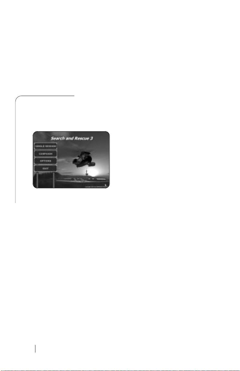
The Menus
▲
This section will explain all features of menus in SAR3. We will go through each screen one by
one, and explain each button and text as we go along.
Search And Rescue 3 - Main Menu
Single Mission
Here you gain access to the single mission features and screens. There you
can set-up and play a single mission chosen from the entire mission list.
Campaign
In the campaign you can start a new pilot, or load an existing one. You will
then gain access to your pilots career data, and continue the service in the
RESCUE RULES AND, flying more missions!
Options
Here are set-up screens for graphics, controls and sound.
Exit
Here you can exit the game, and return to your windows desktop.
10
Page 11
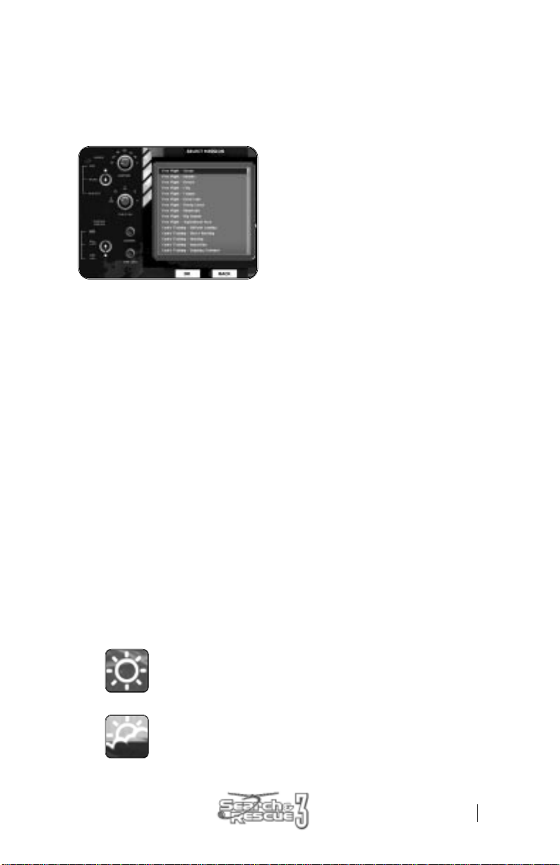
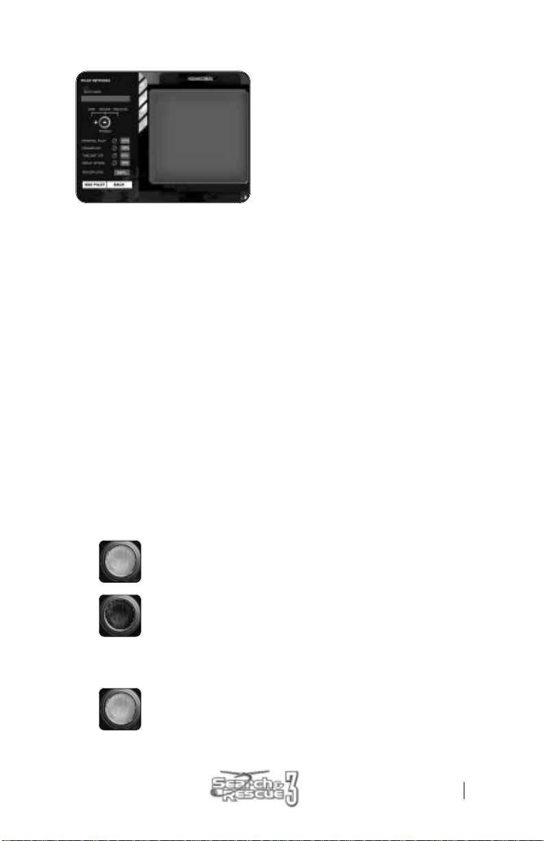
Single Mission Settings menus
This section will explain all features of the single mission screens, and will allow you to set-up a
custom rescue mission.
Choosing a Mission
This screen shows a list of all missions in SAR 3,
and will also let you set up certain flight settings for
that mission. You can scroll down the list of missions
using the scroll bar (or arrows) on the right.
If you click with your left mouse button on a mission
name, you will see that it is highlighted by a blue
box. This means that you have selected that mission.
When you have chosen mission and modified the desired options, click “OK”.
If you want to go back to the previous menu, click “Back”.
Choosing the Single Mission Flight Settings
The right side of the screen holds a panel with a number of buttons. Each button will let you
customize a particular flight setting.
Below is an explanation of each button and the setting it affects.
Physics Switch
Mouse click on the metal switch with the mouse to select between the three settings: Easy,
Arcade or Realistic. The difference between these is described later in this document, but as
a rule you should select “Realistic” for sensitive control, and “Arcade” for safer flight, and
“Easy” if you are a beginner and have no joystick.
Weather
The weather setting you chose will influence wind, light, visibility and rainfall. You change
between the settings by clicking on the dial button.
Each setting is shown as a small icon, graphically illustrating the weather type it represents.
They are explained below (Note that the wind strengths below show the constant “background” wind, but that occasional wind gusts more forceful can be experienced):
Sunny: The visibility is very good and the wind is light.
This is by far the easiest setting!
Wind strength between: 2-10 knots
Overcast: The sky is grey and the mood is gloomy, but flight
conditions are still good.
Wind strength between: 6-20 knots
11
Page 12
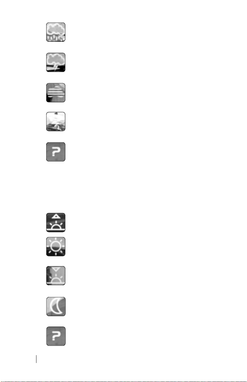
Fog: A dense fog covers the landscape, and long-range visibility is poor.
Helicopter control is still easy though!
Wind strength between: 2-6 knots
Rain: Rain and fog makes visibility poor.
The wind is also slightly increased.
Wind strength between: 6-30 knots
Storm: Wind is strong, making control of the helicopter challenging.
Additionally you will have to fight with both fog and rain.
Wind strength between: 10-30 knots
Hurricane: This is absolutely insane. Normally an aircraft would not go up in
this weather, but if you are up to the challenge, here you get the chance.
Wind strength between: 30-60 knots
Random: If you want to have the computer chose for you, this is the setting
to select. The computer makes a random selection of the previous six
weather types. The result will then be shown on the mission briefing screen.
Time of Day
The time of day setting you chose will mostly influence the light level in the game. You change
between the settings by clicking on the dial button.
Each setting is shown as a small icon, graphically illustrating the time of day it represents.
They are explained below:
Morning: The morning is misty and cold.
Mid day: This is the normal setting for a rescue flight.
The sun is high and the light is good.
Evening: The sun is setting and the sky is
red with its last rays.
Night: It is pitch dark. This is not a setting for beginning player.
It will be nearly impossible to find any visual fix points, and you will
have to rely heavily on instruments.
Random: If you want to have the computer choose for you, this is the
setting to select. The computer makes a random selection of the previous
four types. The result will then be shown on the mission briefing screen.
12
Page 13
Start Position
Here you choose where to start the mission. The most realistic setting is of course to start
from the base, but for training purposes we have included the other two possibilities.
Base: The helicopter stands stationary, with the engines off at the base. You
will need to go through the start-up procedure and power up the engines
before you can take-off.
Hover: The helicopter is hovering in the air just over the base. You are ready to
turn your bearing towards the mission site. This setting can be used if you do
not want to go through the entire start-up procedure.
Mission site: The helicopter is hovering near the mission site. This setting is
good when you want to practice the rescue procedures used for each accident, without having to fly all the way to the site first.
Crashes Off
This button looks like a light. You alternate between the settings by clicking on the light
switching it on or off.
Off: Choosing yes will make your helicopter indestructible. You will be able to
collide with any obstacle without inflicting any damage on hull, wheels or rotor.
Additionally you will never encounter damage on engines and gearboxes nor
be able to over-speed rotors.
On: Your helicopter will take damage and possibly be destroyed if you
collide with anything.
Time Limit Off
This refers to the optimal time limit within which the mission must be completed to avoid
getting a deduction in points.
Off: Time limit is off, and you will not be penalized for completing the
mission using more time then optimal. However you will still have to
deal with the survivors and their worsening health condition.
On: The time limit is on. The player will be awarded for fast completion
of the mission.
13
Page 14
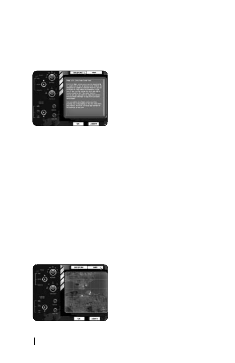
Mission Briefing
This is the mission briefing. Information details about the mission are given here.
When you have read the text and are ready to fly, click “Take off”.
If you want to go back to the previous menu, click “Reject Mission”.
Below is a description of each entry.
Mission Settings
The left side of the screen is now locked, but it stays to remind you of the current weather
and other mission settings.
Mission Description
The mission description box holds several elements. First of all it shows the time of day
(Hours: Minutes) and the Distance to the mission site (from the start position of the
helicopter). You are not obliged to use this information, but they are helpful. It also shows
the wind strength and the direction.
The central text gives a short description of the accident that has happened. Sometimes you
will learn a lot from this briefing, such as number of victims, victim condition or hints on rescue procedures, but more often the information available is limited to hints or suggestions.
At the bottom of the text box is shown the estimated mission time. This is not the time you will
need to spend in front of the computer, but it is the time that the missions would take in reality.
(The SAR3 time-jump function cuts away much of that time).
Map
The mission-briefing map shows an overview of the
area in which the mission/ accident site is located.
(During flight you will also be able to access this
map by pressing “F1”, and then it will show the
area over which you are currently flying.)
14
Page 15
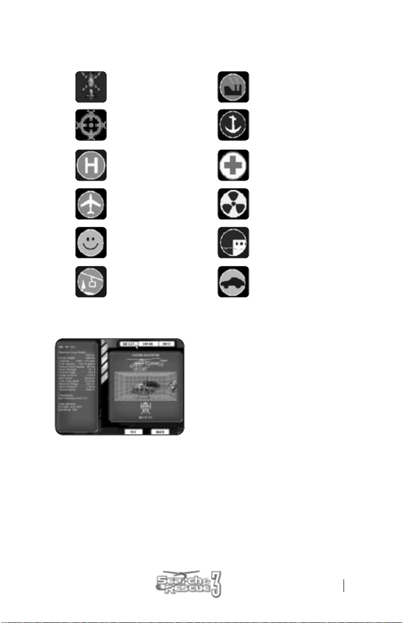
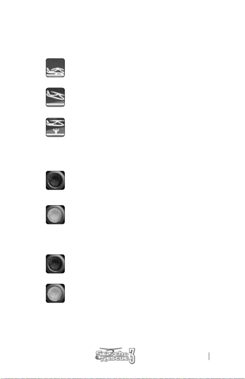
Important locations are marked on the map using small icons.
The icons used are explained below:
The helicopter. Factory.
Mission waypoint marker. Harbor.
Helicopter landing pad. Hospital.
Airport. Nuclear plant.
Theme park. Pier.
Cable rail. Racetrack.
Selecting a Helicopter
The last choice you will need to make is which helicopter you would like to fly.
You select helicopter by clicking the buttons at the top of the screen.
When you have made your choice of aircraft for the mission, click “FLY”.
If you want to go back to the previous menu, click “BACK”.
15
Page 16

Campaign
The following section will describe the screens related to playing a campaign.
Setting up Pilot and Campaign
This screen shows a list of slots. Each slot has room for one pilot name. The text “- Empty slot”
means that no pilot has yet been created there.
You select a pilot (or an empty slot) by clicking on the name. You have selected a pilot when
the slot is lit with a dark blue background. When you have selected a slot you will be able to
access/ modify it by using the buttons on the bottom left. They are explained below.
Click the “Back” button if you want to exit the campaign menu.
New Pilot
Clicking this button will create a new pilot in the selected slot. If you try to
create a new pilot in a slot already used by another name, you will be given
a choice to continue (and delete the old pilot) or to cancel.
If you go on to create a new pilot you will enter the “New Pilot” menu
screen (described later in this manual).
Load Pilot
Dead Pilots
16
If you want to continue a campaign with a pilot already created you will
have to load his information. Select the pilot name from the list, and press
this button. You will then enter the “Running Campaign” screen (described
later in this manual).
If you see this skull icon next to a pilot’s name it means that he is dead.
You will still be able to load his data and review his log (as long as you do
not overwrite him with a new pilot), but you will not be able to continue
the campaign.
Page 17
Creating a New Pilot
Here you can create your new campaign pilot. This data will be used throughout the campaign
of that pilot and cannot be changed later on. It is therefore important that you think about what
you want before selecting the options. (See descriptions below).
When your pilot has been created and you are ready to continue, press: “Add Pilot”.
If you change your mind and want to return to the campaign menu, press: “Back”.
Pilot Name
Click on the empty box to type in the name. The mouse cursor will disappear while you type the
name. When you are finished and have typed in the name you want press return. This will give
you back control of the mouse.
The pilots name has no influence on the game itself. It will only be used on the “Hiscore” (High
score) list and for saving the pilots data after each mission. You can therefore choose any name
you want.
Physics Switch
Mouse click on the metal switch with the mouse to select between the three settings: Easy,
Arcade or Realistic. The difference between these is described later in this document, but as
a rule you should select “Realistic” for sensitive control, and “Arcade” for safer flight, and
“Easy” if you are a beginner and have no joystick.
Immortal Pilot
Crashes Off
On: Your pilot can never die. Even if you suffer a total crash during a mission,
and the helicopter explodes into a thousand pieces will he be able to go on.
Off: Your pilot is mortal and will die if you suffer a serious crash during a
mission. If your pilot dies the campaign is terminated and you cannot
continue with the pilot.
On (Selected): Turning the light on will make your helicopter indestructible.
You will be able to collide with any obstacle without inflicting any damage
on hull or rotor. You will still be able to encounter engine failures or other
flight problems though.
17
Page 18
Off (Not Selected): Your helicopter will take damage and possibly
be destroyed if you collide with anything. If this happens you will
be penalized with points during the debriefing.
Time Limit Off
This refers to the optimal time limit within which the mission must be completed to avoid getting
a deduction in points.
On (Selected): There is no limited amount of time within which the mission
must be completed, and you will not be penalized for completing the mission
using more time then optimal. However you will still have to deal with the
survivors and their worsening health condition.
Off (Not Selected): There is a limited time to complete the missions.
The player will be awarded for fast completion of the mission.
Replay Option
On (Selected): You will be able to cancel the outcome of a mission, by
choosing the replay option on the debriefing menu. This is good if you
have made errors during a mission, but is of course not very realistic.
Off (Not Selected): There is no option to undo/ replay a mission. Once the mission is completed you are forced to accept the outcome, and take any consequences it might have on your pilots career.
Realism Level
This is not an option, but shows the sum of the realism percentages of the above chosen settings. This has no influence on the game itself, but it will influence the amount of points gained
after each mission. In this way you will earn less points for flying easy, and more points for risking your neck (like a real RESCUE RULES AND pilot).
Full point (100% realism) is obtained by choosing no to all realism settings.
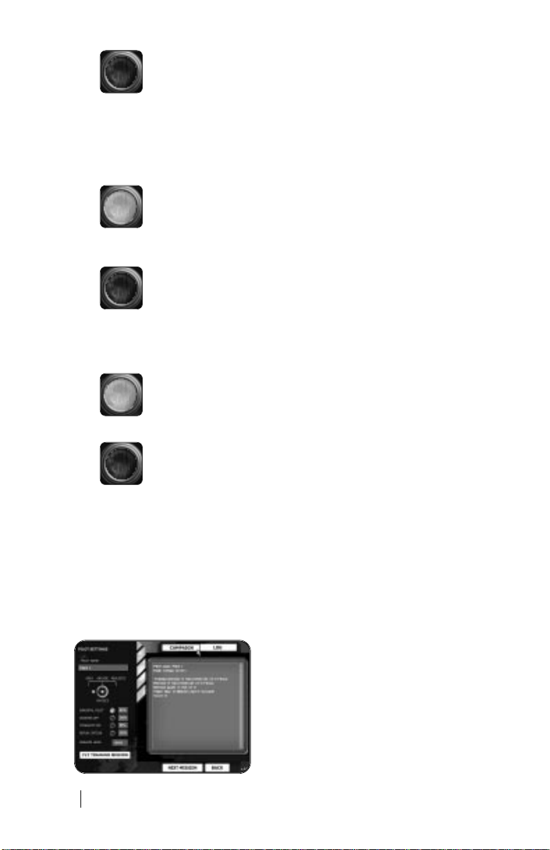
Running Campaign
This screen holds all information about the pilot and
his career. It is the main screen of the campaign and
from this screen you gain access to all other things
related to your pilots career.
18
Page 19

The two buttons at the top of the screen will switch the information in the display area
between “Campaign” information and the pilots “Log” file.
(The content of each screen is described below).
The “Training Mission” button in the lower left corner will let you fly a mission that will
not influence your pilot’s career, though it will be recorded in your Log.
To play the next mission in the campaign, press “NEXT MISSION”.
To go back to the pilot screen, press “BACK”.
To go back to the campaign screen, press “Exit Campaign”.
Campaign Information
Pilot Name
As mentioned before the pilots name has no influence on the game itself. Here it is used
to inform you of what pilot you are playing now.
Pilot Rank
This is a little bit of spice included from the real RESCUE RULES AND service. Here you are
given ranks according to the number of flight hours you have in the helicopter. We have
adjusted the
ranking system a bit to fit SAR 3 but it should still resemble real life close enough.
You will gain rank in the following way:
Rank Required
Ensign, Level 1 ......................................0 Flight hours and 0 successful missions.
Ensign, Level 2 ......................................20 Flight hours and 12 successful missions.
Lieutenant junior grade......................40 Flight hours and 30 successful missions.
Lieutenant..............................................80 Flight hours and 60 successful missions.
Lieutenant commander.......................120 Flight hours and 90 successful missions.
Aircraft commander............................200 Flight hours and 120 successful missions.
Missions
Here you can see the number of missions flown opposed to the number of successful ones.
Mission Goals
Here you can see how many mission goals you have completed out of the number encountered.
Mission goals include injured people needing to be saved, objects to deliver or vessels to
inspect.
Flight Time
Flight time shows how much time you have spent in front of the computer with this pilot. It will
gradually increase as you fly more missions.
Note that this is not the time we base the gain in rank on. (Later in this document
you will see that we operate with two different times for a mission: Flight time and
Mission time.)
Score
Shows how many points this pilot has scored throughout his career.
19
Page 20

Pilots Log Information
The Pilots Log is a tool to help you remember what you did and what should
not be repeated. It is a mix between a real pilots log, with information about the mission and the
helicopter, and a game log keeping track of points and progress. The Log is essentially a text file,
which is updated every time you finish a campaign mission. Each mission has its entry with
information of how things went.
Debriefing
After completing your flight session (even if you crashed) you will come to the “Debriefing”
screen. Here you get information about the outcome of the mission, and how you handled
yourself and the helicopter.
On the right side of the screen are the points given for each accomplishment. They are added
together, and the total is given in the lower right corner. However the total will never be negative, even if the sum of points given to you is negative. You will never get lower then 0 points.
Additionally you should note that the Realism Level modifies your point total (slightly).
The left side of the screen show you the settings as they were for the mission. These are
shown for reference purposes, and you will not be able to handle the buttons or switches in
any way!
When you have read the “Debriefing” and are satisfied with the result, press “OK”. Depending
on what kind of mission you had been flying you will then
return to either the “Single mission” menu or the “Running Campaign” menu.
If you are dissatisfied with the result, you will be able to fly the mission over again by pressing
“Replay Mission”.
Note: This function will not be available if you are playing in Campaign mode and
have clicked the replay option off for your pilot!
Mission Outcome
This is the primary parameter for success or failure. You can encounter the following outcome
messages:
Message Explanation
Successful..............................................You have returned to the base and all mission goals
Failed.......................................................No mission goals obtained, or helicopter crashed.
Partly successful..................................You have returned to the base but only some mission
Not completed.......................................The mission was exited before final touchdown at the base.
Mission failed, Pilot dead................... You crashed and the pilot was killed.
Free flight mission................................ The mission is a fr ee flight mission and no points are given.
20
have been completed.
goals were completed.
Page 21

Mission Goals
Here you can see how many mission goals you have completed on the mission. Mission goals
include injured people needing to be saved, objects to deliver or vessels to inspect.
An injured person mission goal will only be considered complete if he has been safely delivered to the drop-off site/ hospital.
be awarded points).
(I.e. if he dies in the helicopter before drop-off you will not
Mission Time
Here you get points for completing the mission within the estimated (optimal) mission time (
“Briefing screen”
deducted points for being too slow!
). You get points for completing the mission faster than estimated and are
See
Helicopter Damage
Here you are informed about any damage you may have inflicted on the helicopter during the
mission. Points will be deducted for damages (of course).
Errors
This is a list of errors that you have made during the mission. Often these errors will come from
breaking the RESCUE RULES AND rescue procedures or from violating standard helicopter flight
rules. Points will be deducted for each error you make, and the total can be seen in the point
box to the right of the “errors” text.
(A complete list of errors that will be reported can be found under “Rescue procedure errors”
later in this document).
Realism Level
This is just for your reference a reminder of the realism level set during your pilot creation. This
number represents the percentage of the point sum you will be awarded.
Options
This screen has 3 sub screens, which can be selected using the flags at the top: Graphics,
Sound and Control. Each sub screen is described below.
When you have finished modifying the option screens you can press “OK” to get back to the
main menu!
Options Screen
21
Page 22

Options / Sound
Here you set up the sound volume for Voice,
Sound Effects (SFX) and Music. You use the
sliders to set each parameter from 0% on the
left to 100% on the right.
Options / Graphics
Here you set up the graphical detail level of the game. You use the sliders to set each parameter
from 0% on the left to 100% on the right.
Remember that higher detail level will result in a lower in-game frame-rate, but in return you get
a much more eye pleasing flight environment.
Landscape Detail
Here you set the polygon detail level of the landscapes height structure. Low settings will make
the landscape seem more “square” and a high setting will make it look smoother.
Object Distance
This slider actually has 5 settings, and will snap to the nearest when you drag the marker. It is
the setting for the surface detail level of the landscape. Low setting will make the landscape coloring look low, and a high setting will make it look more detailed and varied.
Tree Detail
This defines the density of trees in the landscape. Low setting will make the tree areas less
dense (0% will remove all trees), and a high setting will make tree areas denser.
Note that some areas have no trees even at the highest tree Detail level!
Building Density
This has been included mostly to increase the frame rate speed over the bigger cities. Low setting will remove houses from the city (but also rural areas), and a high setting will put more
buildings in the city.
Note: If you want to see the cities as we have created them, you will need to set this to 100%.
Lens flare
This is an On/Off switch. You can remove the camera lens flare effect of the sun by choosing the
no switch.
Poles
Again something we have included to help you increase the frame rate speed on slower
machines. You can remove all Electrical Wire masts by choosing the no switch.
22
Page 23

Options / Control
This menu will let you set up which control device to use for flying the helicopter. You can set up
Joystick axis’s X, Y, Z and R. Additionally you can set up mouse X and Y axis’s and the Keyboard
as well (Though there is no function to set up individual keys, which means you will always have
to use the keyboard for other functions then those mentioned on this screen!).
Use the arrow keys to select which axis to use, or alternatively you can try the preset buttons.
The column called “Inv.” is used for inverting the poles on the axis.
Here follows an explanation to the different axis (Note: before you try to set up your
control device manually we recommend that you have a look at the preset buttons
explained later in this section.)
Axis on the controller Explanation
Axis X...................................................This sets the controls for the left / right movement
Axis Y ...................................................This sets the controls for the forward / backward
Axis Z ...................................................If your joystick has a slider / throttle, it will most
Axis R...................................................This is usually the axis used for pedals.
Pitch
Changing “pitch” is the same as raising or lowering the nose. The normal controller used here
is the Joysticks Y axis.
Roll
The helicopter is “rolling” when it is tilting from right to left. The normal controller used here is
the Joysticks X axis.
of the controller.
movement of the controller.
likely be this axis.
Collective
The collective stick is used to raise and lower the altitude of the helicopter. Normally this is set
to keyboard, unless you have a collective slider or stick on your joystick.
Tail Rotor
This is used to change the heading of the helicopter at low speeds. Normally this is set to
keyboard, unless you have a set of pedals attached to your computer.
Presets
We have included these preset buttons to ease the process of setting up controllers for SAR2.
Each button represents a specific preset control set up as explained below.
If you start modifying any of the preset set-ups the light will switch off to indicate that you
are no longer using a preset.
Keyboard only.
Joystick only.
23
Page 24

Joystick with Throttle stick (collective).
Joystick with Throttle stick (collective) and pedals.
Mouse control of pitch and roll.
Custom setting. Changed to fit desired
controller set up by the user.
Helicopter Info
This screen is a graphical and visual information screen, listing all the technical data of the HH-65
Dolphin helicopter, as well as displaying a hires animation of the helicopter.
During a Mission
▲
This section will deal with the basic functions of the in-flight part of SAR 3. It will explain anything
you need to know about the game play of SAR 3, except details about flying the helicopter and
following the rules of the RESCUE RULES AND, which will be explained elsewhere in this manual.
Camera Views
The main game screen shows the flight landscape and the helicopter from an angle set by the
selected camera (keys 1-to 0 on the keyboard). The default start screen shows the helicopter
from behind (Camera 3) and the lower part of the screen shows the 2D instrument panel (toggled
with “Q” on the keyboard).
For each camera you will be able to set the panning angle. This is done with the numbers on the
numeric keypad. Each camera will pan differently from the others.
Below is a description of the three most important view angles.
Tail Camera (Number 3)
This is the default camera view, and is considered the easiest way to fly the helicopter. It is of
course not a very realistic viewpoint, but it will help you to judge the distance to the ground and
objects easier. Additionally you will have a good view of the surrounding landscape.
This camera is also good in hoist situations, especially if you pan the camera to get the hoist
door in sight.
24
Page 25

Cockpit Camera (Number 1)
This is the most realistic viewpoint from which to fly the helicopter. You see the inside of the
cockpit from the seat of the aircraft commander, and your view of the surrounding landscape
is limited accordingly. Your pan keys are also important here, but you will then often be using
them to look at the landscape outside, trying to get a fix point or to judge the exact position
over an object.
This view is more difficult then the Tail Camera, but will probably give you a better “realistic”
feeling of the helicopter..
Hoist Camera (Number 2)
This is the view of the Flight Mechanic looking out of the hoist door. If you want to stay as
close to real life as possible this is the camera to use during a hoist. From here you will be
able to scan the water surface for drifting survivors, but also follow the progress of the
rescue swimmer.
Other Cameras
Here is a list and brief description of all cameras in the game.
Camera Description
Cockpit Camera (Key 1).........................This is the pilot chair view. (Explained in depth above)
Hoist Camera (Key 2).............................This is the view of the Flight Mechanic.
Tail Camera (Key 3) ................................This is the default rear view. (Explained in depth above)
Trace Camera (key 4).............................This is much like the Tail Camera,
Right Side Camera (Key 5)....................The helicopter seen from the right.
Left Side Camera (Key 6)......................The helicopter seen from the left.
Top Camera (Key 7)................................Top view of the helicopter.
Bottom Camera (Key 8).........................The helicopter seen from below.
Circling Camera (Key 9).........................A camera that rotates around the helicopter,
Fly-by Camera (Key 0)............................A camera fixed to one point,
(Explained in depth above)
except it has a smooth follow curve.
Good for hoist operation.
Good for getting into position above a target.
but constantly facing it.
but following the helicopters movements.
Transparent Cockpit Option
During flight and especially landings it can often be difficult to see anything just outside of the
cockpit. This is often the problem with computer flight simulators, where you (as a player) do
not have the same ability as a real pilot to move your head to the side, or lean forward in the
seat. Of course SAR3 offers the ability to look around inside the cockpit, but not to the same
extent as a real flesh-and-blood pilot is able to do.
To compensate for the lack of visibility we have added the “Transparent cockpit function”. You
can activate this function only when you are inside the cockpit and press the designated key
(default this is “U”). The cockpit will then become transparent, and your field of vision is
greatly increased. This should help you during difficult landings and low altitude hovers.
Mission Flow
Generally speaking all missions follow the same pattern. There is a series of steps necessary to
complete the missions in SAR3 (as well as in real life RESCUE RULES AND rescues), and you will
be expected
25
Page 26

to master all to perfection if you want to attain the highest rank of the game.
Here each step is explained in brief:
Step Description
1: Engine start. ......................................Making checks and starting the engine
2: Take off..............................................Lifting off and attaining hover
3: Finding the site................................Gaining speed, finding the direction.
4: Rescue check...................................At the site. Making the rescue check
5: Rescue procedure..........................Picking up survivor/ mission objective
6: Check survivor condition..............Checking survivor injuries
7: Secure check ...................................Securing cabin, gaining speed
8: Drop off survivors............................Landing at hospital or drop-off site.
9: Return to base..................................Back to base. (Possibly also time jumping)
10: Landing..............................................Slowing down and landing (See “Take off and landing”)
(See “Take off and landing”)
(See “Take off and landing”)
(Possibly also time jumping)
(See “Rescue and secure checks”).
(See “Rescue procedures”).
(See “Survivor condition”)
(See “Rescue and secure checks”).
Delivering survivors.
(Note: Some missions will of course deviate in one way or another
from this step by step procedure).
Campaign Flow
The flow of each individual mission in the campaign is just like that of the single missions
(explained above), but the order in which you play and generate missions is different and randomly chosen by the computer.
Randomly Generated Missions
Each time you play a new mission in a campaign the computer will randomly set up a mission
based on a set of parameters. First of all the mission will be chosen based on your rank. All
the missions in the game have a difficulty level matching one of the ranks that your pilot can
gain. The computer selects a random mission from between all the missions having a difficulty
low enough for your rank.
Then the computer will randomly set the weather type and time of day. This selection is again
restricted somewhat by your rank, making low ranked missions easier. (I.e. you will not be
allowed to fly night missions as an ensign!)
Finally the location of the mission site is set. Even this is randomized somewhat, where the
computer selects between a set of predetermined locations appropriate for that mission type.
The above system makes virtually all missions in the campaign different, and each campaign
will therefore vary both in difficulty and “story line”.
Flight Area
There are 10 different landscapes in SAR 3, all of which spans 20x20 kilometers. To fly over a
specific landscape you will have to choose one of the free-flight missions, where you can fly
freely with no mission limitations or time jumps.
26
Page 27

Reason for Limited Areas
The landscape system is based on the same concept as in SAR 2, where flight was limited to
an enclosed map. The reason for the limited area size is that we wanted to have as high a
ground level detail as possible. During research and based on feedback from real pilots, we
realized how important static fix-points in the landscape are for maintaining hover position
and visually judging altitude. Therefore we have chosen to include a very high ground detail
level, both with the number of objects and with the ground textures.
Time Jump
As mentioned above, each area in SAR3 covers 20x20 kilometers. However as most missions
start in one area with the accident site in another, you will need to switch to the second area at
some point during the missions. The process of switching landscapes is called “time jumping”.
There are two ways in which a time jump can be activated: voluntary and forced. A forced time
jump occurs when the player nears the edge of the 20x20 kilometers landscape. You will be given
a warning that you are close to the edge, and that time jump is necessary, but if you do not heed
this (turning back) you will time jump automatically.
A voluntary time jump occurs when the player uses the “L” key to time jump to the next waypoint
in the mission. However several criteria have to be met before this is possible. These are:
1: The next Waypoint of the mission has to be in another area.
2: The helicopter has to be flying at airspeed higher then 40 KIAS.
3: The helicopter has to face in the general direction of the waypoint
(as indicated on the HSVD instrument).
Effects of a Time Jump
When you time jump the helicopter is moved to the edge of the target area in an instant. The
screen fades to black, while the computer loads the new area into memory. When the screen
fades up again you will find yourself in the air flying at approximately 120 KIAS, and heading
straight for the waypoint.
Even though the flight between the areas is not played in the game, it will still be calculated into
the mission time. This also means that fuel is used and time passes for the victims.
Point System
We have decided to include a point system in SAR3 because it is a good way to award players
according to their performance. This is especially true for the RESCUE RULES AND rescue elements of the game, where several rules and procedures have to be followed in order to make a
safe rescue (See the “RESCUE RULES AND rescue procedures” section for more details).
The point system is completely independent from the rank system (explained under
the “Running Campaign” menu screen). This means you can have a huge amount of
points and still be an ensign.
(See also the “Debriefing” menu screen description)
27
Page 28

Rescue Rules and Procedures
▲
This section explains how to use the rescue diver and what the rules of the game are. They are
based on the RESCUE RULES AND rescue procedure rules, modified to fit the game play of
SAR3.
Many of the rules can be broken, while still completing the mission, but doing so will result in a
point penalty awarded at the debriefing. So completing a mission perfectly is not only a question
of being able to fly the helicopter, but also a matter of following the rescue rules.
Rescue Equipment
A rescue helicopter is rigged with lots of gear and devices. Of most importance to SAR 3 are
the three rescue devices: Basket, Sling and Litter. Each one of these is used attached to the
hoist cable as a method to transfer the hurt and injured into the helicopter.
Rescue Basket
The rescue basket is the primary device for hoisting individuals in most situations. It affords a
measure of protection for the individual being hoisted from vessel rigging etc., particularly for
an untrained person.
The rescue basket is used when hoisting survivors suffering from mild to medium injuries.
Sling
The sling is an efficient method to deliver and pick up personnel trained in its use. Due to the
danger of falling out, it is not recommended for use with those not specifically trained in its use.
The rescue sling is used when hoisting unhurt individuals or rescue personnel.
Litter
In rescue situations where the survivor is incapacitated, the rescue litter is used. The litter is
more difficult to use in a hoist, primarily due to its larger size and sail area.
The rescue litter is used when hoisting badly hurt or dying survivors.
Spotlight
Each helicopter is fitted with spotlight (also called search light). In real-life this spotlight is
controlled by the pilot or the flight mechanic using a small joystick placed inside the crew
compartment. The spotlight is used at night or in poor visibility conditions to search for survivors on the ground or in the water.
In SAR3 the spotlight is fully controlled by you. You can turn the spotlight on and off using the
(default) key “F9”. You can move/ aim the spotlight by holding the CTRL button while using the
NUM PAD keys for direction control.
Flight Crew
Pilot
In essence you take the role of the pilot, being responsible for the safe and orderly conduct of
the flight. You are in full control of the helicopter controls, and the commander of solving the
mission. (The crewmember you see sitting next to you inside the cockpit is the co-pilot, but
you will have no control of his actions).
Flight Mechanic
The flight mechanic is the person responsible for control of the hoist. He is also the one in
command of the rear cabin in the helicopter, and is trained to check the condition of the survivors once they are picked up.
You have control of most duties belonging to the flight-mech, including hoist operation, rescue
28
Page 29

swimmer deployment, supervising external load operations, cargo loading and off-loading,
operating the hoist door, visual area search, and deploying rescue devices.
Rescue Swimmer
The rescue swimmer is trained to be deployed from the helicopter and act independently
while preparing survivors for pickup. When the rescue swimmer is used, the swimmer will
participate in the on-scene evaluation, and advise the flight-Mechanic (player) on which rescue device to lower according to the victim’s condition.
The rescue swimmer has the authority to decline deployment if the situation is beyond the
swimmers capabilities (though you will be able to drop him above the maximum drop height).
The rescue swimmer is used in many different ways, both over water and on land, and can be
deployed both by hoist and by dropping from the helicopter (called “free fall”).
Rescue and Secure Checks
During a mission when you get ready to commence with the rescue procedure, there is a set
of checks that has to be made (both before and after the main rescue procedure). The beforecheck is called “Rescue check” and the after-check is called “Secure Cabin check”. In SAR 3
the Flight mechanic and Pilot will go through these automatically once you have opened the
hoist door. They are listed here for reference reasons, but also because it is important that you
wait for them to be completed before you go on with the main rescue procedure.
RESCUE CHECK
• Hatch open......................................(“F2”)
• Hoist power......................................Flight Mech says, “Request Hoist Power”.
• Hoist rigged.....................................Device or diver gets ready for procedure
• HOT MIC on.....................................Flight Mech says, “HOT MIC check”.
• Ready................................................Flight Mech says, “Rescue check complete, ready aft for
(Attached to hoist or ready in door).
____”. (The empty line indicates that the ready message will
vary from each rescue procedure type.)
(After this the appropriate rescue procedure will commence)
SECURE CABIN CHECK
(This check is made when the rescue procedure ends, and the cabin door (Hatch) is closed, and
the HOT MIC is off.)
• Hatch Closed...................................(“F2”)
• Hoist boom.......................................Flight Mech says, “Boom stowed,
The Flight Mechanic must stand by the Cabin door until safe single engine speed (40 KIAS).
When 40 KIAS has been reached the check will continue.
• Hoist power request......................Flight Mech says, “Secure Hoist Power”.
• Secured............................................Flight Mech says, “Cabin Secure”.
ready for forward flight”.
Rescue Procedures
This section describes how the functions and procedures for rescuing people works in SAR 3.
It will give a detailed description of each of the mission types in the game, and how you
should act at the mission sites.
29
Page 30

Procedure Descriptions
In Search And Rescue 3 each mission must be completed using one of
8 rescue procedures.
Each of the 8 procedures has been created to mimic the United States Coast Guard procedures as closely as possible. In this manual we will explain only what is needed to go through
the procedures in the game, and if you want to know more about the real-life rescue procedures, we suggest that you contact your nearest air-rescue station.
When you play a mission you should be able to deduct which procedure to use by reading
through the briefing text carefully. This will give a clear short description of what you must do
when you arrive at the mission site. Each of the mission types are described in the following
procedure:
Required Action at Site Procedure Described in Section
Land & pickup using stretcher...........................Stretcher deployment.
Land & deliver........................................................Land and deliver.
Land on object & deliver......................................Land and deliver.
Direct hoist deployment of RS............................Direct deployment. (Using the rescue diver)
Radio inspection....................................................Radio inspection.
Hoist object up from target..................................Hoist pickup.
Hoist object down to target.................................Hoist delivery.
Free fall or sling deployment...............................Free fall or sling deployment.
Free flight................................................................Free flight (not really a rescue procedure).
(Using the rescue diver)
Stretcher Deployment
This procedure requires the pilot to land the helicopter, so that the stretcher carriers will be able
to exit the helicopter.
1. The pilot establishes the helicopter in a stable hover placing the survivor at the one - to
- two o’clock position, well outside the rotor wash. Then touches down to a stationary
and secure position, and the pilot reports, “We have touch down”.
2. When the rescue check is complete (you must open the door to activate it), the FM
reports “Rescue Check Complete, Ready aft for Stretcher Deployment.”
3. The pilot voice directs “Go on HOT MIC,” “Check Stretcher”.
4. The FM responds “On HOT MIC,” “Checking Stretcher”. When this is done the FM
reports “Stretcher Ready”.
5. The pilot commands, “Deploy stretcher”.
6. You are now allowed to deploy the stretcher (“F3”). When this is done
the FM reports “Stretcher on the ground,” “Moving for survivor”.
7. Once the rescue is complete, with stretcher and all survivors aboard, FM reports,
“Stretcher in Cabin.” You will then be required to close the door before he reports
“Going off HOT MIC”, and begins secure check. The pilot maintains position until FM
reports, “Ready for take-off”.
30
Page 31

Land and Deliver
This procedure requires the pilot to land the helicopter, so that the passengers or cargo can be
delivered safely.
1. The pilot establishes the helicopter in a stable hover above the touch down area.
(In most cases you will be required to find a suitable location based on your own
judgement). Then touches down to a stationary and secure position, and the pilot
reports, “We have touch down”.
2. Now the FM will direct, “Open the door to unload passengers/ equipment”.
You can now close the door, take off and return to base.
3. When all has been delivered the FM reports “Passengers/cargo
delivered”. You can now close the door, take off and return to base.
Direct Deployment
This procedure includes the Rescue Swimmer. In a Direct Deployment the RS uses the seat
harness and remains attached to the hoist cable throughout the rescue process. The RS is
lowered to the survivor, applies the quick strop and indicates ready for pickup. The swimmer
and survivor are hoisted together!
1. The pilot executes an approach to a hover with the survivor(s) at the
one - to - two o’clock position, outside the rotor wash.
2. When the rescue check is complete (you must open the door to
activate it), the FM reports “Rescue Check Complete, Ready aft for
Direct Hoisting.”
3. The pilot voice directs “Go on HOT MIC,” “Check Swimmer”.
4. The FM responds “On HOT MIC,” “Checking Swimmer”. When this is done the FM
reports “Swimmer Ready”.
5. You are now allowed to deploy the swimmer to the rope (“F4”). When this is done and
the swimmer is attached to the rope, the FM reports “Swimmer outside door,” and will
continue to report the swimmers location throughout the hoist.
6. When the swimmer touches the ground, FM reports “Swimmer in contact with the surface”. Once secure footing has been established, the RS approaches the survivor via
walking/ rappelling, and you must lower the cable to let him move freely.
7. When the swimmer reaches the survivor, he will prepare the survivor for pickup (securing him in the quick strop). When the survivor is secured and ready, the FM will report
“Ready to be hoisted”.
8. Once the rescue is complete, with swimmer and all survivor(s) aboard, FM reports,
“Swimmer in Cabin.” (You must remember to unhook the
hoist device as well (“F6”)).
9. You will be required to close the door before the FM reports “Going off HOT MIC”, and
begins secure check. The pilot maintains position until
FM reports, “Boom stowed, ready for forward flight”.
10. Finally when a steady rate of climb and 40 KIAS has been reached, the FM finishes
with the secure check.
31
Page 32

Keyboard Reference Sheet
32
Page 33

33
Page 34

Radio Inspection
This is not actually a rescue procedure, but will be considered as such in SAR2 game terms.
Here the pilot makes a radio call to a vessel, checking its registration numbers or customs
codes.
1. The pilot executes an approach to a hover near the vessel
to be inspected.
2. When he is within range he will make a radio call, reporting to
you “Inspecting Vessel.” (You will not hear the exact content of
the radio communication).
3. When an inspection of one vessel has succeeded the pilot reports “Vessel Inspected”.
If there are more vessels to inspect you will then have to close in on these as well, but if
there are no more and all
vessels have been cleared the procedure will go on to next point.
4. When all information has been gathered from all vessels the pilot
reports “Inspection Completed,” “Return to Base”.
Hoist Pickup
This procedure is used when something is hoisted into the helicopter without the help of the
Rescue Swimmer, and usually it requires the use of one of the three rescue devices described
elsewhere in this document.
1. The pilot executes an approach to a hover above the survivor or
object to be hoisted.
2. When the rescue check is complete (you must open the door to activate it), the FM
reports “Rescue Check Complete, Ready aft for _____ Deployment.” (The empty line
indicates that the report will depend on what device must be lowered, and so it will in
the following text. The devices are Basket, Sling or Litter).
3. The pilot voice directs “Go on HOT MIC,” “Check _____”.
4. The FM responds “On HOT MIC,” “Checking _____”. When this is done the FM reports
“_____ Ready”.
5. You are now allowed to deploy the designated device to the rope (using either “F5”,
“F6” or “F7”). When this is done and the device is attached to the rope, the FM
reports “_____ outside door,” and will continue to report the location of the device
throughout the hoist.
6. When the device has been lowered to the survivor/ object and is held there for a short
while, it will automatically attach to the device. Then the FM reports “Survivor in
_____,” “Ready to be hoisted”
7. Once the rescue is complete, with device and all survivor(s) aboard (You must
remember to unhook the hoist device manually (“F5”, “F6” or “F7”)), FM reports,
“_____ in Cabin.”
8. You will be required to close the door before the FM reports “Going off HOT MIC”,
and begins secure check. The pilot maintains position until FM reports, “Boom
stowed, ready for forward flight”.
9. Finally when a steady rate of climb and 40 KIAS has been reached, the FM finishes
with the secure check.
34
Page 35

Hoist delivery
This procedure is used when something is hoisted from the helicopter to the ground or a vessel
without the help of the Rescue Swimmer, and usually it requires the use of one of the three
rescue devices described previously in the section called “Rescue Equipment”.
1. The pilot executes an approach to a hover above the survivor or object to be hoisted.
2. When the rescue check is complete (you must open the door to activate it), the FM
reports “Rescue Check Complete, Ready aft for hoist deliver.”
3. The pilot voice directs “Go on HOT MIC,” “Check _____”. (The empty line indicates
that the report will depend on what device must be lowered, and so it will in the following text. The devices are Basket, Sling or Litter).
4. The FM responds “On HOT MIC,” “Checking _____”. When this is done the FM
reports “_____ Ready”.
5. You are now allowed to deploy the designated device to the rope (using either “F5”,
“F6” or “F7”). When the device slides out, the FM reports “_____ booming out”.
6. Now in some hoists you will be required to manually deploy the object or person to be
hoisted (“F4”). When this is done you can start lowering the hoist.
7. When the person/object has been lowered to the delivery site and is held there for a
short while, it will automatically detach from the hoist. Then the FM reports
“Passenger delivered”. (If there are more persons you must repeat the procedure until
all have been delivered). When the last person has been delivered, the FM reports “All
mission targets secured, Return to base”.
8. Once the delivery is complete, with device and all survivor(s) aboard (You must
remember to unhook the hoist device manually (“F5”, “F6” or “F7”)), FM reports,
“_____ in Cabin.”
9. You will be required to close the door before the FM reports “Going off HOT MIC”,
and begins secure check. The pilot maintains position until FM reports, “Boom
stowed, ready for forward flight”.
10. Finally when a steady rate of climb and 40 KIAS has been reached, the FM finishes
with the secure check.
Free Fall or Sling Deployment
This procedure includes the Rescue Swimmer. Free fall or sling Deployment of the RS is only
used over water.
1. The pilot executes an approach to a hover with the survivor(s) at the one - to - two
o’clock position, outside the rotor wash.
2. When the rescue check is complete (you must open the door to activate it), the FM
reports “Rescue Check Complete, Ready aft for free fall or sling deployment.”
3. The pilot voice directs “Go on HOT MIC,” “Check Swimmer”.
4. The FM responds “On HOT MIC,” “Checking Swimmer”. When this is done the FM
reports “Swimmer Ready”.
35
Page 36

5. You are now allowed to deploy the swimmer. This can be done in one of two ways. The
decision of which to use will be entirely up to your judgement.
A) FREE FALL DEPLOYMENT: With the aircraft in the desired position and altitude, the
pilot commands “Deploy Swimmer.” Maximum hover altitude for freefall is 15 feet
RADALT. You must check the area below the helicopter for debris before you deploy the
swimmer (“F3”). When the RS is released the FM reports “Swimmer away”, then
“Swimmer in the water”.
B) SLING DEPLOYMENT: Attach the swimmer to the rope (“F4”), when the aircraft is
in the desired position over the target. You must the lower the hoist, and when the
swimmer reaches the water he will report “Swimmer in the water”. When the RS is
clear of the sling, the FM reports “Swimmer away”.
6. After safe water entry of the RS the FM reports “Swimmer OK”. Now you must move
the helicopter left and back to place the RS outside
the rotor wash.
7. The RS will now act on his own swimming towards the nearest survivor in the water.
When the RS has reached the survivor, the FM reports, “Move in for pickup”. The RS
will now head for the helicopter.
8. When the RS enters the rotor wash the FM reports “Deploy _____”. (The empty line
indicates that the report will depend on what device must be lowered, and so it will in
the following text. The devices are Basket, Sling or Litter).
9. You must then hook the appropriate device on to the rope (using “F5”, “F6” or “F7”), and
then lower this down to water level where the RS is waiting with the survivor. The RS
will then place the survivor in the device and when ready the FM reports “Ready to be
hoisted”.
10. If there are more victims in the water the RS will swim for them and you must repeat
the above hoisting procedure again until all has been picked up. Finally you will need to
hoist the rescue swimmer.
11. Once the rescue is complete, with swimmer and all survivor(s) aboard, FM reports,
“Swimmer in Cabin.” (You must remember to unhook the hoist device as well (“F6”).
12. You will be required to close the door before the FM reports “Going off HOT MIC”,
and begins secure check. The pilot maintains position until FM reports, “Boom stowed,
ready for forward flight”.
13. Finally when a steady rate of climb and 40 KIAS has been reached, the FM finishes
with the secure check.
Free Flight
Free flight is not really a rescue procedure and has no checks or points that need to be
cleared. In free flight you are able to fly as you please with no time limit on your hands. Free
flight missions are especially good for training flights and skill improvement (see the section
called “Flying the Helicopters”).
If you want to have an “official” mission completion to a free flight mission you will need to
land the helicopter at the start site. The HSVD will point in that direction during the flight.
36
Page 37

Survivor Condition
Your primary task in SAR3 will be to find the injured persons and pick them up. But your mission
does not stop here. Some of the survivors you have picked up may have suffered an accident so
severe that their life is slowly ebbing, and their only salvation will be proper hospital care.
Therefore once the rescue situation at the accident site is over, you will be in a race against
time to get the survivors to a hospital before their strength run out.
Injury Types
All survivors in SAR3 have been given a unique set of health condition characteristics. These
will vary from simple concussion to gun shot wounds or heart attack.
The type of injury a survivor has will depend on the type of accident. Additionally it will be randomized a bit from mission to mission, which will make each time you play a mission a little different from the previous.
Effects of Injuries
A survivors injury type and condition has three important effects on the game:
1. The type of rescue device to be used when hoisting will depend on what type of injury
the survivor’s has suffered. (I.e. a man with a broken leg needs to be hoisted in the litter,
where a man with broken arm can use the basket).
2. The type of injury will dictate the drop off site. (I.e. a man with a gunshot needs to go to
the hospital, but a man who is mildly shaken can be dropped of on a parking lot).
3. The severity of the injury will dictate how much time you have left to deliver the survivor
to the drop-off site. (I.e. a man with a gunshot wound will slowly bleed to death, but a
man who is suffering from superficial cuts can stay alive a lot longer).
Checking Survivor Condition
Once you have picked up a survivor the Flight Mechanic will check his condition and give you a
verbal report. He will continue to do so with regular intervals until the survivor has been delivered to a drop-off site. You can also make the check manually by pressing “F8”.
If more then one survivor has been picked up, the FM will report the condition of the survivor
suffering the most.
Condition Report
The Flight Mechanics condition report is given as an overall estimation of the survivor’s current
health condition. (The exact injury type is shown in the “Console” 2D instrument). This
estimation is based on how long the survivor has left before dying. Below is a list and
description for each condition report:
Condition report Meaning of report
No Victims.........................Means you have no survivors in the rear cabin.
Victim Is Dead..................Means that a survivor has just died. FM is now checking the next.
Stabilized (or stable).......Survivor is in good health. (More then 500 seconds left to live)
Unstable.............................Survivor is weak. (Between 200-499 seconds left to live)
Critical................................Survivor needs hospital care NOW! (Between 100-199 seconds
Victim Is Dying..................Survivor will die within the minute! (Between 1-99 seconds left to live)
All Survivors Dead ...........All the survivors you picked up have died in the helicopter.
left to live)
37
Page 38

Errors During Flight
During a mission in SAR 3 you will have to follow certain rescue procedures as well as a set
of basic helicopter flight safety rules. The procedures are explained previously in the section
called “rescue procedures” and most of the flight rules are explained throughout the sections
about the individual helicopters and the section called “Flying the Helicopters”.
This section shows a summary list of all error messages as they will be shown on the debriefing
screen (under errors). A short description follows each error listed.
Device Deployed Before “Rescue Device Ready” Signal was Given
This error refers to the hoist procedures where you are using the sling, basket or litter. You will
see this message if you have violated the rescue procedure rules by attaching any of these to
the rope before the appropriate checks were made. (Violating this rule in real-life can result in
hoist failures or un-secure attachment of the devices!)
Equipment Deployed Before “Equipment Ready” Signal was Given
This error refers to the hoist procedures where you are lowering equipment down from the
helicopter. You will see this message if you have violated the rescue procedure rules by
attaching the equipment to the rope before the appropriate checks were made
Flying Over 135 KIAS with Gears Down
The maximum wheels-down safe speed is 135 KIAS. On the “Airspeed Indicator” instrument
you will see this limit marked with a red line. You will see this message if you exceed this
speed with the gears down, or lower the gears while flying above this limit.
(This error can of course not be reported if you fly the BK-117, as it has no wheels!)
Flying Over 40 KIAS with Cable Out
The maximum cable-out safe speed is 40 KIAS. You will see this message if you exceed this
speed with cable out, or lower it while flying above this limit.
Flying Over 40 KIAS with Object Mounted on Hoist
The maximum safe speed with an object attached to the hoist wire is 40 KIAS. You will see
this message if you exceed this speed with an object attached, or attach an object while
flying above this limit.
.
Flying Over 60 KIAS with Hoist Door Open
The maximum safe speed with the rear cabin door open is 40 KIAS. It will be dangerous
both for the rear cabin crew as they might fall out, but also concerning the general flight
conditions. You will see this message if you exceed this speed with the door open, or open
the door while flying above this limit.
Helicopter Damaged
You will see this message if you damage the helicopter in any other way then by a
collision. (Except for total crash which is accounted for under “Helicopter damage”
on the debriefing menu).
Helicopter Damaged because of Collision
Any kind of collision between the helicopter and ground or object is considered extremely
dangerous. Even the slightest collision could result in damage.
You will see this message if you collide with anything. (Except for total crash which is
accounted for under “Helicopter damage” on the debriefing menu).
Lifted Off before Ready Signal was Given
During takeoff it is important for the rotor to be at full rpm before commencing with lifting off.
You will see this message if you lift off from the ground before the rotor is at full speed and
you have been given the “Ready for take-off” message from the pilot voice.
38
Page 39

Lifted Off while Stretcher was Deployed
During land and pickup missions where the stretcher is deployed it is important that you do not
go flying around while the stretcher carriers run for the survivor. You will see this message if you
lift off while the stretcher is in the field.
No Mistakes Made
This is of course not an error, but an indication of faultless flying!
(Except for total crash which is accounted for under “Helicopter damage”
on the debriefing menu).
One or More Survivors Damaged by Downwash
The downwash from the helicopter puts a lot of air pressure on those directly under the helicopters rotor. This is especially dangerous for weakened or injured people trying to stay afloat in the
water. You must therefore take care not to hover too close to lone survivors in the water. You will
see this message if you hover close over a floating survivor for too long.
Pilot Dead, Campaign Terminated
You will see this message if you crash the helicopter and your campaign pilot dies.
Rescue Device Collision with Object During Hoist
You will see this message if a device attached to the rope collides with anything during a hoist.
Rescue Diver Died
This is a rare occasion and has to my knowledge never happened in real life. The rescue diver
can be killed if he hits a boat or other object during a free fall drop to the water.
Stretcher Deployed before “Stretcher Ready” Signal was Given
This error refers to the rescue procedure called “Land and pickup” where you use the
rescue stretcher. You will see this message if you have violated the rescue procedure rules
by deploying the stretcher before the appropriate checks are made.
Swimmer Damaged by Downwash
Like survivors the rescue swimmer can also take damage from the heavy air pressure of the
downwash. However he has been trained and is in fit shape to handle himself in the water.
Therefore you will only see this message if you have really strained the strength of the swimmer
and have been hovering extremely close to the water surface.
Swimmer Deployed before “Swimmer Ready” Signal was Given
This error refers to all rescue procedures where the rescue swimmer is used. It is very
important that all security checks of straps, hoist and equipment are completed before the
swimmer jumps from the helicopter. You will see this message if you have violated the rescue
procedure rules by deploying the swimmer before the appropriate checks were made.
Swimmer deployed closer than 5 ft from survivor
To ensure both swimmer and survivor safety it is important (especially in freefall deployments)
that you do not deploy the swimmer too close to the survivor. You will see this message if you
have violated the rescue procedure rules by deploying the swimmer closer then 5 feet from
the survivor.
Swimmer dropped from above 15 ft RADALT
To ensure swimmer safety in free fall deployment it is important that you do not deploy
the swimmer higher than 15 feet from the water surface. The 15 feet level is marked in the
“Radar Altimeter” instrument by a white line. You will see this message if you have violated
the rescue procedure rules by deploying the swimmer from an altitude above 15 feet
over water level.
39
Page 40

Wrong rescue device lowered
To ensure fast and easy recovery of all survivors it is important that commands and directions
between all crewmembers are understood and followed to the point. It is therefore important
that you lower the correct rescue device as requested by the swimmer. You will see this message if you lower a wrong rescue device to the swimmer.
The Helicopters of SAR3
▲
The BK-117 C-1
Known for its outstanding multi-mission capabilities, the BK-117 C-1 can handle the most
demanding missions, and it is one of the most versatile and functional medium twin-engine
helicopters in the world.
The arrangement and layout of the medical outfit according to functional aspects is based on
thousands of successful rescue missions and the close cooperation with rescue helicopter
operators.
TECHNICAL SPECIFICATIONS(BK 117 C-1)
Weights:
Maximum Gross Weight............ 7385 lbs
Empty Weight .............................. 3869 lbs
Powerplants:
Two Turbomeca Arriel 1E2
Capacity ........ 1 Pilot + 7/10 passengers
Fuel Capacity.................. 184 US Gallons
Rescue Hoist Capacity................ 800 lbs
Aircraft Dimensions:
Rotor Diameter ................................36.1ft
Overall Length.................................. 32.6ft
Height to top fin............................. 12.63ft
Performance:
Max Speed ................................ 150 knots
Fast Cruise Speed.................... 133 knots
Maximum Range 292 nm (nautical miles)
Max Endurance........................... 3 hours
Service Ceiling.............................. 10000ft
The RESCUE RULES AND HH-65A Dolphin
First flight of the Aerospatiale/Eurocopter Dauphin took place on June 2, 1972. Since then,
several variants have been built with roles spanning over e.g. passenger/VIP transport, cargo
lifting, naval defense and reconnaissance, close air support and last, but not least Search
And Rescue missions.
The RESCUE RULES AND HH-65A Dolphin (as seen in SAR2) variant has search and rescue
(SAR) as its
primary configuration. Its two pilots side by side can fly missions in almost any weather
conditions. The crew compartment, up to three crewmembers can perform hoist
operations, be deployed as rescue swimmers and take medical care of rescued victims.
40
Page 41

TECHNICAL SPECIFICATIONS(HH65A Dolphin)
Weights:
Maximum Gross Weight.............9369 lbs
Empty Weight...............................4940 lbs
Powerplants:
Lycoming LTS-101-750B-2 Gas Turbines
Capacity...........2 pilots + 11 Passengers
Fuel Capacity................................1900 lbs
Rescue hoist Capacity..................600 lbs
Aircraft Dimensions:
Rotor Diameter................................39.17ft
Overall Length .................................38.15ft
Height to top fin.............................13.32 ft
Performance:
Max Speed.................................165 knots
Fast Cruise Speed.....................150 knots
Max Range........ 400 nm (nautical miles)
Max Endurance..........................3.5 hours
Service ceiling...............................7520 ft.
The Sikorsky SH-3 Sea King
Born as the “Sea King” antisubmarine helicopter for the US Navy originally named HSS-2, the
SH-3 is available in different models and is now used by several countries.
Sikorsky built more than 1100 of the original S-61s model, and the prototype lifted off first time
in March 1959. Later Sea king was also built in Great Britain by Westland as “Sea King” and
“Commando”, in Italy by Agusta as AS.61 and in Japan by Mitsubishi.
The Canadian naval model is known under the name SH-3 Sea King.
TECHNICAL SPECIFICATIONS
(Sikorsky SH-3 Sea King)
Weights:
Maximum Gross weight.......... 21000 lbs
Empty Weight........................... 11865 lbs
Powerplants:
Two 1400 shp General Electric T58-10
Capacity ......2 pilots + 10/15 passengers
Fuel Capacity .............................3500 lbs
Rescue Hoist Capacity................ 800 lbs
Aircraft Dimensions:
Rotor Diameter.................................. 62 ft
Overall Length.................................... 55 ft
Height to top fin.................................. 17ft
Performance:
Max Speed................................ 140 knots
Fast Cruise Speed.................... 116 knots
Maximum Range 469 nm (nautical miles)
Max Endurance........................ 5.5 hours
Service Ceiling............................ 14700 ft.
41
Page 42

In the Cockpit
In this chapter, we will take a look at all the handles, buttons and dials in the cockpits, and
explain how they work. You will not learn how to fly the Helicopters here, but you will learn
about the instruments that are essential for flying them.
In our description of the instruments we will describe them in general terms that refer to all 3
helicopters in SAR3. However, the helicopters are different in several aspects, and we have
made notes if it in our description where instruments or functionality of one helicopter differs
from what we describe.
Flight Controls
A helicopter pilot uses all his limbs to make the helicopter behave as he intends it to. The right
hand is holding a stick protruding from the floor in front of the pilot. It is called a Cyclic. The
left hand is holding a grip called a Collective, and his feet rests on a set of pedals.
The cyclic can be moved along two axes: Moving it forward will make the nose of the helicopter go down, and moving it aft will make the nose pitch up. Moving the cyclic sideward controls bank: If the cyclic is pushed to the left, the helicopter will bank to the left, and vice versa.
Usually, the joystick on your computer will control the cyclic, but you can also use the cursor
keys or the mouse.
The collective can be moved in one direction only. When it is moved, the helicopter generally
does not change attitude. If it is pulled upwards, you will climb, and if it is lowered, you will
descend. If you have a joystick with throttle, you should assign this as collective. Otherwise,
use mouse or keyboard.
The pedals control in which direction the nose is pointing: moving it from side to side. They
are connected in such a way that if one is pushed down, the other one will go up. If you push
the left pedal, the nose will turn towards left, and vice versa. Pedal game controllers are ideal
for this purpose, but a twisting motion joystick, mouse or keyboard can also be used.
Landing Gear Controls
This section on landing gear is only relevant for the HH-65 and the SH.3 helicopters.
Toggling the “G” key (as assigned pr. default) will move the landing gear up and down. This
corresponds to moving the gear handle to the bottom left of your instrument panel. When the
gear is down, air resistance is increased, making it harder to pick up speed and making fuel
economy look bad. For game rule purposes the highest allowed airspeed with gear down is
135 knots. For landings, you must of course remember to put the gear down again.
A helicopter that is equipped with wheels is able to drive on the ground. Many helicopters
with wheels actually land on a runway, and then “taxi” to its designated parking space in the
airport.
Once the helicopter has stopped it will be necessary to lock the wheels. Wheel brakes on the
main gear can be toggled using the “B” key (as assigned pr. default).
Sometimes, even wheel brakes just aren’t enough to stay in the same place. When the
weather gets rough, and the landing platform is the rolling slippery deck of a ship, another
tool comes in handy.
This is the “TALON” decklock system, a hook that shoots down from the belly of the helicopter
and grabs on to a grid of ropes on the deck. When the Talon is armed, it shoots down as soon
as both main gear wheels are touching the deck. It then retracts, keeping the helicopter firmly
on the moving deck. To toggle arming of the Talon, or to release it after use, press the designated key (default is “V”).
42
Page 43

Engine Controls
If you look up and left, in the middle of the roof of the cabin, you will find three levers that control the two engines and the power transmitted to the rotors.
The yellow levers on the left and right sides are Fuel Flow Control Levers. Each can be placed
in three positions: Cut-off, Idle and Flight. The rearmost position is Cut-off, where the engines
will stop. The levers can be moved one step forward to the Idle position by pressing “E” and
“T”, respectively. Now, ignition will be on, and the engines will spool up to idle RPM. Moving
the levers fully forward by pressing the same keys again will take them to the Flight position,
where power will be transferred form the engines to the rotors, bringing the rotors up to flying
speed.
Pressing the SHIFT key and “E” or “T” will move the levers backwards.
The red handle in the middle is the Rotor Brake Control Lever. When in the rear position, the
brake on the main rotor is activated, and when the lever is forward, the rotor is free to move.
The brake position is toggled using the “R” key (default setting).
The fuel flow controls and the rotor brake are interlocked: You have to release the brake
before the fuel flow levers can be moved to the flight position, and you cannot activate the
brake with the fuel flow levers in the flight position.
If you are carrying a heavy load, perhaps even at high altitude or in hot weather, you may have
marginal or insufficient lift available. To get out of trouble, you can dump some of the fuel you
are carrying. The key to toggle the dumping valve between open and closed is “F” (default
setting). The dumping rate is 272 pounds/minute. As a safety guard, approximately the last 150
pounds cannot be dumped.
Instruments
Flying close to the ground means that your most important instrument is the view to the world
outside. Still, a glance at the instruments is required from time to time, and sometimes the visibility may be so bad that the instrument panel is your only guide to safe flight.
Your suite of instruments include the following:
Flight Instruments
Attitude Director Indicator
Airspeed Indicator
Radar Altimeter
Barometric Altimeter
Vertical Speed Indicator
Horizontal Situation Video Display
Engine Instruments
Triple Tachometer
Triple Torquemeter
Misc. Instruments
Landing Gear Position Indicator
Landing Gear Warning Light
Master WARNING Light
Console
Let’s go through the list instrument by instrument. (Note: All 3 helicopters in SAR contain
similar instruments, and the descriptions in this section are valid for all 3 helicopter
instrument panels. The images of the instruments shown in this manual are all from the HH-65)
43
Page 44

Attitude Director Indicator
In low visibility conditions, this instrument is a substitute for your view
of the outside. The ADI shows the orientation of the helicopter relative
to the horizon. The stationary yellow wing in the middle represents the
helicopter, and the moving blue/brown ball the world. In reality, the ball
is kept stationary by gyroscopes, and it is your cockpit that is revolving
around it. If the wing is in the blue, your nose is up, and if the wing covers
the brown region, you are nose down. If you are banking, the ball will bank
also: If the ball tilts to the left, you are banking to the right and vice versa.
This may sound confusing, but you will see that it works quite well. When
you are less than 200 feet above ground level, a radar altitude pointer will
become visible. This is a green and white horizontal bar that will rise
towards the yellow wing, as you get lower, and touch it when you are at
ground level.
Airspeed Indicator
This dial displays your speed through the air in the forward direction. A
small tube is protruding in the forward direction, and as airspeed builds up,
the pressure changes inside the tube, and this pressure is translated into
the displayed airspeed. As this type of measurement works poorly at very
low speeds, nothing will be shown below 15 knots. If there is any wind, this
will make your airspeed different from your ground speed.
The unit is knots, i.e. nautical miles per hour. The dial is split into some colored regions:
Green band,............0 - 150 kts.........Max weight operating range
Yellow band,...........150 - 165 kts.....Operating range
Red line,...................135 kts...............Max gear out and power off speed
Red line, ..................165 kts...............Never-exceed speed.
Radar Altimeter
You have two instruments that inform you of your current flying height –
it is very important to know in which way they perform differently. Your
Radar Altimeter measures your height above the ground by emitting a
radar pulse downwards and timing its return. Other structures large
enough to reflect the radar signal, like rooftops, ships, etc., will also affect
the radar altitude. The instrument is to the upper right on the panel. This
type of altimeter is only used when flying close to the ground, as is evident
because the scale ends at 2000 feet above ground level (AGL). The scale
is finely graduated and very responsive when close to the ground, and
gets less detailed as you go higher.
Barometric Altimeter
As you get further away from the ground, the Barometric Altimeter is more
practical to use. This measures air pressure, which decreases as you go
higher, and translates it into an altitude. When you enter the cockpit, the
altimeter will be adjusted to show your height above sea level, independent of whatever air pressure the weather conditions dictate. Note that this
altimeter does not show your height above any obstacle, so be careful
when using it close to the ground.
The barometric altimeter is located in the right side of the instrument
In the centre of the display, your altitude in feet is shown as digits. The leftmost number drum
shows hundreds of feet. To the right this is followed by two counters showing thousands and ten
thousands of feet, respectively. At low altitude, the leading zeroes will not be shown.
44
panel, below the radar altimeter.
Page 45

In addition, a needle shows your altitude. Each number on the needle clock is one hundred feet,
so that one complete turn of the needle corresponds to a 1000 ft altitude change.
Vertical Speed Indicator
Below the altimeters, you will find a related instrument, the Vertical
Speed Indicator. This displays how fast you are climbing or descending
by measuring the rate of change in the air pressure. The scale is in thousands of feet per minute, showing up to 3000 FPM in both directions. The
graduation is finer for vertical speeds less than 1000 FPM, which makes
this instrument much easier to use e.g. to maintain level flight rather than
watching the altimeter slowly move.
Horizontal Situation Video Display
When it comes to navigation, the Horizontal Situation Video Display
(HSVD) is the instrument to use. It is a computer screen that shows information provided by the navigation computer. In the centre of it, there is a
small aircraft symbol that represents your helicopter. The symbol is stationary, with the nose pointing in your forward direction and so forth. In a
circle around it, a compass rose is shown. This rotates so that your current heading always can be read under the downward pointing arrow at
the 12 o’clock position. Your mission is planned as a set of waypoints
before take-off. An arrow pointing outwards from the inside of the rosette
shows the direction to the currently selected waypoint. The distance to the
The unit is nautical miles. Your speed is shown in two ways: Inside the rosette, under IAS, your
indicated airspeed is written. This is exactly the same as shown by the airspeed indicator instrument. In the upper right corner, the ground speed is shown under GSPD. This is your forward
speed over the ground, which will usually be different from the IAS because of wind.
waypoint is shown under the DIST label in the upper right corner.
Triple Tachometer
This instrument consists of three colour-coded bars displaying the revolutions per minute (RPM) of your two engines and the main rotor.
The main rotor RPM is shown by the bar in the middle. The Dolphin is
equipped with a throttle governor that automatically tries to keep the rotor
RPM at 100%, or 350 RPM. The allowed range for continuous flight is from
97% to 108%. During normal flight, the main rotor will be very close to
100% RPM, but it can become low if you pull the collective enough so that
there is not sufficient power to keep the rotor speed up. RPM will of
course also go down if you lose engine power. Conversely, RPM can
become higher than 100% if you lower the collective and enter auto-rotation. Be warned that a too high RPM may cause the rotor to break up. You
The turbo-shaft engines have two sets of independently rotating blades. The first set is the compressor, or gas generator stage, which are the ones that you hear spool up when starting the
engines. The second set of blades converts the gas pressure to power for the rotors through a
gearbox. The RPM of this power turbine is what is displayed for each engine in the left and right
sides of the triple tachometer. Because of the gear system, the power turbine RPM will closely
follow the main rotor RPM, whenever the engines are providing thrust. On the other hand, the
main rotor is allowed to overtake the power turbines, so that if no power is required, the main
rotor RPM will be higher than the power RPM. These are also the bars to inspect if you think an
engine failure has occurred. In case a power turbine RPM falls below 84%, the red warning light
over the relevant bar will illuminate.
should get used to listening to the rotor beat rather than looking at this bar.
45
Page 46

Triple Torque Meter
(This instrument can only be found on the 3D panel inside the cockpit)
This instrument is closely related to the tachometer in layout, but instead
it displays the twisting forces, also called torque, inside the gearbox.
The bar in the centre shows the torque transferred to the axis of the
main rotor. This is the sum of the torque from the two engines, shown on
each side of the centre bar. The amount of torque will change as the
throttle governor controls the engines to keep the main rotor at 100%
RPM.
The bars are colour coded: Green indicates the continuous flight range,
from 10% to 88% torque. The yellow range extends from 88% to 100%.
climbing to the desired cruise setting. Above 100%, the three bars become red to indicate a too
high load that will eventually wear down the gearbox. In addition the engine over torque lights
will illuminate above 100%, and above 103%, the main gearbox over torque light will turn on.
This range is allowed for hover and transition, e.g. accelerating and
Landing Gear Position Indicator
(This instrument cannot be found in the BK-117, as this helicopter does
not have retractable landing gear)
Immediately to the right of the landing gear control handle, the Landing
Gear Position Indicator shows the status of the gear. When the gear is
down and locked in place, a green arrow will illuminate for each leg. As
the gear uses some time for moving up and down, an amber caution light
above the three arrows will illuminate whenever the gear is moving.
Landing Gear Warning Light
(This instrument cannot be found in the BK-117, as this helicopter does
not have retractable landing gear).
To remind you of putting the gear down before landing, a Landing Gear
Warning Light will illuminate whenever you are within 200 feet of the
ground and the gear is not down. The warning light is located at the top of
the panel, right in front of you.
Master WARNING Light
When a critical malfunction has been detected, the Master WARNING
Light will turn on, and an audible warning horn will start also.
Acknowledge that you are aware of the warning by pressing CTRL C. The
horn and light will turn off until another critical situation occurs. Of course
you will now have to examine the cause of the warning and take proper
action.
Console
The floor panel between the pilots has screens for entering navigation
data etc. In this simulation these screens are instead used for displaying
information to keep you up-to-date on the mission progress and important
events. Pressing the TAB key toggles displaying the console on/off.
On-Screen Help
The on-screen help box can be activated using the “O” key (default setting). It is placed in the upper left corner of the screen. We have implemented this feature to help beginning players to get through a mission.
When the box is activated its content will constantly be updated with
advice, guidelines and hints on what to do to complete the mission.
46
Page 47

The Flight Computer
Flying a helicopter is a lot of work. Flying a helicopter on a SAR mission in awful weather is
really a lot of work, sometimes so much work that even the best pilot cannot perform well
enough to save the lives of the people in distress. So to help the pilot to concentrate more
on solving the mission and worry less on steering the helicopter, the Automatic Flight Control
System (AFCS) was introduced.
The Automatic Flight Control System
The idea of the AFCS is to keep you, the pilot, in command of the helicopter, while the AFCS
helps making steering simpler. Instead of a direct link between your controls and the rotor
blades, the flight computer collects the input from you, figures out what you want the
helicopter to do, and then moves the rotor blades to make the helicopter do just that.
It sounds nice and easy, and it is so. To experience how flight is without the help from the
AFCS, toggle activation by pressing the “M” key (default key setting). You will find that with
complete manual control, the helicopter is really taxing to steer.
The AFCS controls rotation about the vertical axis, also called yaw axis, in the following way:
Below 40 knots, you will be in “heading hold” mode, that is, your nose will not turn in the sideward direction unless you apply pedals. Depressing a pedal will change the desired heading
by a maximum rate of 30 degrees per second.
At speeds above 40 knots, you are in “auto co-ordination” mode. This means that the nose
will be turned to point into the flow of air. In this way, you are pointing in the direction you
are going and the helicopter body will produce less drag. If you push a pedal, the nose
will turn slightly, but as soon as you release the pedal again, the nose will turn into the
relative wind again.
If you are accelerating through 40 knots with the nose not pointing in the direction of motion,
you will consequently experience a little sideward kick as the AFCS changes mode.
The AFCS treats the pitch and roll movement in almost identical ways, so we will examine
these at the same time. Pitch is the angle the nose makes to the horizon, and roll is the angle
the helicopter banks to the left or right. The pitch and roll angles together define an attitude,
i.e. the helicopter orientation relative to the horizon. The AFCS remembers a “reference
attitude” that it will try to put the helicopter into, if no other cyclic stick inputs are given.
Initially the reference attitude will be horizontal, but you can set it by tilting the helicopter
into an attitude and then pressing and releasing the “Sync/Trim Release” button, which is
the “0” key on the keypad. At the moment of releasing the key, you will have defined a new
reference attitude. You cannot define a very extreme reference attitude, though. The pitch
angle has to be no more than 12 degrees nose up or down, and the bank angle can be 45
degrees at maximum.
You are not allowed to place the helicopter into more dramatic attitudes of 60 degrees pitch
up or down and 60 degrees roll to either side. The AFCS will refuse to let you exceed these
angles. When the deflection of the cyclic is decreased, the helicopter will return rapidly to
an attitude with the allowed reference attitude range, and from then on it will adapt to the
reference attitude at a slower pace.
So what is all this good for? Setting a reference attitude is a way of trimming the helicopter to
a certain state of flight. Every pitch angle corresponds to a specific airspeed, and every bank
angle to a rate of turn. When you have established a desired speed and turn, a quick tap on
the Sync/Trim Release button will make the helicopter stay in that state while you can relax.
When the nose wheel touches the ground, the tendency to return to the reference attitude is
disabled so that the helicopter can settle properly on the surface.
47
Page 48

The Autopilot
Flying at constant altitude and airspeed while navigating through your waypoints or
searching for the source of a distress call is not the hardest thing in the world, but still
requires an amount of attention.
The autopilot can help you to make life a lot easier in such situations. Engage the autopilot by
pressing the “F11” key (default key setting), and push another time to disengage it. When the
autopilot is active, it will take over control of the pitch and collective, and in return keep your
airspeed and barometric altitude constant, at the values at the moment of engaging the
autopilot. You will maintain full control over bank and yaw, which means that you can still turn
to change course. This takes a lot of work out of navigation.
Beware that the autopilot keeps barometric altitude constant. This means that it will not
hesitate to fly right onto a mountain or another obstacle if there are any at that altitude.
So stay alert and be ready to disengage at every moment!
Using the Flight Director Slew Switch, a four way button located on the pilot’s cyclic stick,
can change the reference speed that the autopilot tries to maintain. Holding down the
“Home” key will increase the reference speed at a rate of 4 knots per second, and pushing
“End” will decrease the speed at the same rate. The highest allowed reference speed is
150 knots. In this way, you have very good control over airspeed, even though you cannot
directly control pitch.
It is not quite true that you give up control over pitch. If you push or pull the stick hard
enough, a “fly through” feature will allow your input to override the autopilot input. Still
for complete pitch control, you will have to disengage the autopilot.
Hover Augmentation
Search And Rescue missions often require extremely precise hovering under difficult conditions.
The Hover Augmentation flight computer mode is an invaluable tool here. Activation of this mode
can be toggled using the “F12” key.
Using the ground tracking radar, ground speed is determined in both forward and sideward
directions, and the flight computer steers the helicopter to get zero ground speed in both
directions. If you are more than 50 feet above the ground, the helicopter will descend to 50 ft
AGL and stabilize there. If you are already below 50 ft AGL, the current height will be maintained.
In HA mode, the flight computer takes control of both cyclic and collective, leaving only the
pedals to you. But also here “fly through” is available and very useful. If the cyclic stick is
deflected more than about 1/3 of its full travel, your command will override the flight computer’s
command, and the helicopter will move in a horizontal direction, still maintaining the height over
ground. As soon as the cyclic is released, the flight computer will reduce ground speed to zero
again. This can be utilized for very precise hovering.
The zero ground speed mentioned above is actually a reference ground speed that initially is set
to zero. You may change the reference ground speed using the Flight Director Slew Switch,
implemented as four keys. Pressing a key will increase the reference ground speed in the same
direction by four knots per second. The following keys represent a direction:
Home: ........................................................................................Forward
End:......................................................................................Backwards
Delete:...............................................................................................Left
PgDn:...............................................................................................Right
You should be cautious flying over uneven terrain using this feature, as the height over ground
varies rapidly, forcing the flight computer to try to make similarly rapid height changes.
A little trick: When you have used the slew switch to set a certain ground speed and want
to quickly go back to zero ground speed, rapidly disengage and then re-engage hover augmentation. This will set the reference ground speed to zero. The same trick can also be used for
levelling the reference attitude.
The hovering height can be altered using the three-position Hover Beep switch. In reality
48
Page 49

located on the collective grip, its Up position in this simulation is the “7” key on the keypad,
and its Down position the “1” key on the keypad. For every time it is flicked up or down from
its centre position, the reference hover height will go 3 feet up or down, respectively.
Basic Helicopter Aerodynamics
▲
At first look, it is really mind-boggling that such a strange machine as a helicopter is able to
fly, and even does it well. In this section, we will look at some of the basic principles that
make a helicopter work.
How a Wing Works
A helicopter has no wings - and then again, it has. A fixed wing aircraft flies by moving the
wings through the air at high speed. A helicopter has to work even at a standstill in the air; so
fixed wings will do no good. Instead, the wings of the helicopter are put on a rotating axis and
in that way they are able to move through the air at high speed also when the helicopter is not
moving.
So how does a wing really work? You have probably heard it before; the wing is slightly
curved on the upper side, and this creates a suction force that can be used as lift. Well, that is
correct, but it is not a very useful explanation. Instead, we should start by looking at rockets.
A rocket accelerates because it pushes some mass (propellant) in the opposite direction to
which the rocket is going. This is a very fundamental principle, called Newton’s Third Law:
“To every action, there is an equal and opposite reaction”. The wing works in the same way:
It is pushed upwards because it is pushing air downwards. The way it is pushing is where
the curved upper surface enters the picture.
The Rotor System
The helicopter has to push a lot of air downwards to fly, and that is what the large horizontal
main rotor is for. As the rotor pushes, it transfers energy to the air. The rotor needs to be resupplied with energy constantly, and this is what the engines turning the shaft of the main
rotor do. The turning force, or torque, will make the helicopter body rapidly turn in the opposite direction of the rotor, which is of course very impractical. To prevent this, the vertical tail
rotor pushes on the tail cancelling the turning force of the engines.
Controlling the Helicopter
The helicopter is primarily piloted by manipulating three controls: The collective grip, the
cyclic stick and the anti-torque pedals.
Changing the pitch angle of all rotor blades at the same time controls the lifting force of the
main rotor. This is why the control handle for doing this is called the collective. For more lift,
the forward edges of the rotor blades are pointed more upwards. In the cockpit, the collective
grip is raised to do this. If less lift is desired, the blade pitch is made less steep by lowering
the collective towards the floor.
As mentioned above, you do not get lift for free. As the rotor produces more lift, more engine
power is automatically added to maintain working RPM. This in turn increases the force
making the body rotate about the vertical axis. The way to counter this is to make the tail rotor
push harder on the body also. Just as the collective controls the main rotor pitch, the pedals
control the tail rotor pitch. Of course the tail rotor can be used for more than countering
torque - it can also be used for rotating the body about the vertical axis.
For accelerating in the forward or sideward direction, the main rotor has to be tilted so that
its lifting force is pointing in the desired direction. This is a bit tricky, as every rotor blade is
constantly moving around. This problem is usually solved by a “swash-plate”. This is a ring
around the main rotor axis that can be tilted according to movements of the cyclic stick. If the
cyclic stick is moved forwards or backwards, the swash-plate is tilted in one direction, and
49
Page 50

if the stick is moved sideward, the plate is tilted in the other direction. The swash-plate is
actually two rings that move in the same plane. The lower one is stationary, except for the
tilting motions, and the upper one is rotating and connected by rods to the pitch controls of
each of the main rotor blades. This means that if the swash plate is tilted, the pitch of the
main rotor will increase on one side and decrease on the other side, in spite of this the whole
assembly is spinning very fast at the same time. The pitch change will in turn create a tilting
force on the rotor, and in this way it is possible to control the orientation of the main rotor
and the direction of its lift.
In the following text, you will sometimes encounter the term “vector”. This is just another way
of saying direction. Imagine e.g. a lift vector being an arrow pointing in the direction of the lift
force, and the length of the vector is proportional to the strength of the lift.
With this knowledge, you are ready to learn to fly the Dolphin. As we progress through the
training program, more details of helicopter aerodynamics will be added.
Flying the Helicopters
▲
By reading this section, setting up and flying the practice situations described, you should be
able to acquire enough skill as a helicopter sim. pilot to take up this simulation’s challenge of
a career as a search and rescue pilot.
If you have flown other helicopter simulators, you might be able to do fairly well if you skip
this training course and start out on the missions right away. But chances are that you will
be missing something vital covered here.
In the training lessons it is assumed that you have selected the “Realistic” physics. If you do
not want to bother with all this training, you might want to jump in and fly about in the “Easy”
or “Arcade” physics modes. But if you really want to experience the details of the simulation,
you should use the “Realistic” mode only.
But if you really want to experience the details of the simulation, you should use the “Realistic”
mode only.
Training Flight Set-up
You will define the training flight yourself, using the menu system. First make sure that your
controls are set up properly in the “Options” menu. In the main menu, select “Single Mission”.
You will then be prompted for a mission type/ name. The free flight missions are ideal for this
purpose, as mission goal and time limit will not distract you. You will have several options
available in the next menu screen. Select “Realistic” at the “Physics” entry. For the first
missions, you should select the sun symbol for both “Weather” and “Time of day”. Turn the
“Time limit” off.
When you start the mission, you will be looking at the helicopter from behind using the tail
camera. You can use this view or the trace camera for the training, but the most realistic
experience of course requires you to use the cockpit camera. If you use the outside views,
turn on the 2D instrument panel. Inside the cockpit, you may find the 2D panel the easiest to
use, but you can also use the 3D-cockpit panel.
50
Page 51

Forward Flight
▲
Let us first look at flight manoeuvres with plenty of forward speed.
At a speed of 40 knots or more, you will find that the Dolphin is particularly easy to control,
and in many ways behave like a fixed wing aircraft. Below 40 knots, auto-coordination will be
disabled and the handling changes considerably, so stay out of that regime for now.
For all forward flight exercises, set up a flight session as described above, and in addition select
the flying helicopter symbol at the “Start position” entry.
Straight and Level
When you enter the simulation, you should be pretty much set up for straight-line flight. Now we
just need to keep it that way. In this exercise, you will only need to use the collective and the
pitch control of the cyclic. Look at the vertical velocity indicator, and adjust the collective until
the needle settles at zero. Do not concentrate only the needle, but get a feel for the delay in
between moving the collective and a new vertical speed is established. When you are satisfied,
move on to controlling your airspeed at the same time. If the airspeed indicator shows you are
slowing down, lower the nose a little and vice versa.
Changing Speed
When you are able to fly level at a fixed speed, try to change airspeed while maintaining altitude.
Decide a new, higher airspeed, and accelerate towards it by putting the nose down. Note how
you lose altitude at the moment the nose goes down. Your main rotor lift is about the same as
before, but it is now pointing more forward and less up, so you are consequently dropping. The
proper way to accelerate is therefore to add a little collective as you put the nose down.
The next step is to decelerate to a lower speed while staying at the same altitude. Tilting the lift
vector backwards by raising the nose does this. Perhaps surprisingly, you now have to decrease
collective a bit to stay level. The explanation for this is that the rotor and body is now transforming some of your forward energy to extra lift. If you pitch up strongly, you will hear the main rotor
pick up speed. Be careful not to over speed the rotor, as it might break apart.
Turns
A turn is made by banking, which will point the lift vector towards the inside of the turn.
As you do this, you will decrease the upward pointing component of your lift vector, so you
will have to add more collective. As you start practicing level turns, note your altitude and
your heading on the horizontal situation display before entering the turn, and decide the
heading at which you will exit the turn.
If you are used to flying fixed wing aircraft, you will be tempted to pull back on the cyclic to get
the lift required to turn. Don’t! This will just make you slow down. Instead, keep the nose low
enough to maintain airspeed.
It is a good idea to adopt a favorite angle of bank and always use that when turning. This will
give you a good idea of your turning radius and the time to complete a turn, which will be much
harder if you use a different bank angle each time. Your bank angle could be a modest 30
degrees, where the rotor is only required to produce 15% more lift than in level flight. Or you
could opt for 45 degrees, where 41% more lift is required. This means the helicopter will feel
41% heavier, also described as pulling 1.41 G’s. A higher bank angle will be impractical. 60
degrees of bank will require you to pull 2 G’s, which is not possible if the helicopter is heavily
loaded with fuel and cargo - see the section on stalls below - and you will also be fighting the
bank limiter of the AFCS.
As a rule of thumb, you should start rolling out of the turn when the remaining heading change is
half of your bank angle. So, let’s practice turns: Start flying straight and level, and make a mental
note of your altitude and airspeed. Slowly increase bank to 30 or 45 degrees while watching the
vertical velocity indicator. Increase collective to keep the VVI needle at zero. Keep turning while
maintaining airspeed and altitude. Then level out while decreasing the collective to establish
51
Page 52

straight and level flight.
When you are getting the hang of it, decide on a new desired heading before entering the turn,
and exit the turn at precisely that heading.
Climb and Descent
Climbing while flying straight ahead is quite simple: Adjust the collective until the desired rate
of climb is achieved. The engines have to work harder, so watch the over torque warning lights.
Around an airspeed of 70 knots, you will be able to climb at a rate of about 2000 feet per minute
with full tanks, while at both lower and higher speeds, performance will be less.
Descent is also a simple process. You just lower the collective to produce less lift. Use a shallow
descent whenever possible, you will then avoid two dangers: A steep descent may result in
rotor over speed, and the nose is blocking sight of where you are going.
When you are comfortable with climbing and descending while flying on course, you can try
combining these with a gentle turn.
Using Reference Attitude
Moving the cyclic stick in the helicopter, you will feel a force that will try to push it back into
a neutral position, very similar to the centering force of a computer joystick. Flying at a certain
attitude, especially at high speeds, will require you to constantly push the stick. This can be
quite tiresome and will adversely affect the precision of your input.
When you have established a desired attitude, you should press and release the Sync/Trim
Release button. The AFCS reference attitude will then change to your current attitude, and
you can relax the forces on the cyclic.
Using the Autopilot
Even more comfort is available using the autopilot. When you have established an adequate
cruise altitude and airspeed for travelling to the next waypoint, you will probably want to activate the autopilot. Try to perform level turns in this mode. Easy, isn’t it? Also try to adjust your
cruise airspeed using the Flight Director Slew up and down buttons. Be nice to the autopilot, and
it will be nice to you. It controls altitude quite aggressively, so if you engage the autopilot while
in a climb or dive, it will try to stop the vertical motion abruptly, which may be an unpleasant
experience. So try to be flying straight and level at the moment of engaging.
Asymmetric Lift and Retreating Blade Stalls
The rotating wings of the helicopter makes it able to do things no fixed wing aircraft could
attempt, but there are also some problems associated with using rotors for getting lift. While
hovering, all blades move through the air at the same speed, but as the helicopter starts
moving forward, the situation gets more complex: The main rotor of the helicopters rotate
clock-wise seen from above.
We will call the blades on the left side of the advancing blades and those on the right side of
the retreating blades. At high-speed forward flight the advancing blades will have a tremendous
airspeed, as the total airspeed is the sum of the helicopter speed and the rotating speed. On the
other side, the retreating blade will move much slower as the two speeds are in the opposite
direction here. As the rotation speed increases with radius, the tip of the retreating blade will
still move through the air at a fair speed, while the innermost section with very little rotational
speed will move backwards through the air.
As difference in speed means difference in lift, the angle of attack (AoA) of the advancing blade
is decreased and the AoA of the retreating blade is increased to compensate for this. If no compensation were made, the helicopter would start rolling to the right as soon as it moved forward.
At some point, increasing AoA of the retreating wing does not help anymore. It fails to produce
more lift and stalls instead. In such a retreating blade stall, lift is lost on the right side of the helicopter, and you will start to roll to the right and loose altitude.
To recover from a retreating blade stall situation you will have to lower the forces on the rotor,
52
Page 53

i.e. require less lift from it. Do so by lowering the collective and centering the cyclic. Resist any
temptation to try to roll in the opposite direction using the cyclic. It will only make things worse!
Better yet than recovering is to avoid the stall at all. This means that you should be very cautious when manoeuvring at high speeds. And note that the conditions: heavily loaded helicopter,
high altitude, warm weather and low air pressure are all making the stall appear earlier.
The retreating blade stall begins at the root of the blade and moves outwards if the load increases further. You will still be able to fly with the inner section stalled and the outer part producing
adequate lift. In this case, the inner section will produce turbulence and vibrations, warning you
of a fully developed stall if you increase the rotor load.
Hovering
▲
The ability to fly at low speed and even hover is what makes the helicopter the best or only
choice for performing certain missions. Handling the helicopter at low speed is a very different task from forward flight, and generally involves a lot of manipulation of all controls, including the pedals, which are rarely used at high airspeeds.
During the hover, you rely mainly on visual references, and your instruments are of little use.
To start with good visual feedback, select a mission that takes place over ground e.g. the “Car
Crash” rescue. Even if you prefer the cockpit views, you should initially try some of the external views, as these are better for examining the hover.
To get started right away, select the hovering helicopter symbol at the “Start position” entry.
Note that hovering start is not available for the free flight missions. When you jump into the
mission, you will be in “hover augmentation mode”, which means that the flight computer
keeps your ground speed and vertical speed at zero. When you are ready, disengage hover
augmentation by pressing the “F12” key (default key assignment).
Ground Effect
First, let us get proper control over your height. There is a fair chance that you start out with a
collective position that is far away from the required position for hovering, so you may be initially
climbing or descending rapidly. Adjust the collective until you achieve zero vertical speed.
Then try to change the collective position a little, and observe a peculiar effect: When you are
quite close to the ground, about a rotor diameter or less, you seem to settle at a certain height
depending on the collective position. This is called the “ground effect”. The downward flow of
air from the main rotor is being increasingly deflected by the ground as you get closer, and this
increases rotor effectiveness. In effect, it requires less power to hover the closer you are to the
ground. This is also why two maximum hover altitudes are listed in the technical specifications:
A quite high “In Ground Effect” altitude, and a lower “Out of Ground Effect” altitude.
Some tricky situations may occur: If you are hovering over sloping ground, the down flow can
escape easier, and ground effect will be reduced. When taking-off from the roof of a tall building, you should be careful when passing over the edge away from the building, as the ground
effect will suddenly disappear.
The air cushion below the helicopter will only exist when your airspeed is low. As soon as you
start to move, the ground effect will be reduced. This also goes for hovering in wind: You may
have zero ground speed, but if your airspeed is considerable, the ground effect will weaken.
Manoeuvres During Hover
When you have established a steady hover altitude, you should practice moving around.
Keep the ground speed low to stay in the ground effect, and be prepared to support with
a little collective if you start sinking.
Your forward and backward speed is controlled with cyclic movements in the same directions.
When moving backward, you should of course be absolutely certain that there are no obstacles
behind you.
53
Page 54

Sideward motion is similarly controlled with side ward movements of the cyclic. Notice that
even at a completely level attitude, you drift a little to the left. This is an undesired effect of the
tail rotor: When it pushes the tail to cancel torque, it also pushes the entire helicopter a little.
So a completely stationary hover actually means that you have to bank slightly to the right.
The AFCS keeps your heading steady while in a hover, but you can rotate about your vertical
axis using the pedals.
When you have practiced all these motions one by one, it is time to do them all at once. A most
rewarding exercise is to find an isolated object like a tree, and hover in a perfect circle around
it, while always pointing the nose at the tree.
Hovering Climb and Descent
Large altitude changes while hovering should generally be avoided. You will of course have to
make height adjustments in the hover, but that should be all. Climbing with near zero airspeed
is very inefficient. It is much better to accelerate to about 70 knots and climb at that speed.
Descending in a hover should be avoided because you cannot really see where you are going.
Also, you can enter a dangerous situation called “Settle with Power”, which is described
below.If you make a sufficiently fast vertical descent, you will move along with the air that your
main rotor has just thrown downwards. This air is very eddy and turbulent, so it will be a rough
ride. The air will be re-ingested by the main rotor and thrown downwards once again. This is
practically useless: The air will form a vortex around your main rotor, and you will drop like a
rock. If this happens near the ground, you are obviously in trouble. You can get out in two
ways: Pull the collective all the way up to use all the available engine power to get out.
Maybe you have the power, maybe not. The other way is to lower the collective to fall even
faster and enter auto-rotation (see below). Both methods can be combined with putting the
cyclic forward to get some horizontal speed. In general, avoid near-vertical powered descent
at a higher rate than 500 feet per minute.
Hover Augmentation
By now, you have found out that hovering is hard work. It can be a lot easier if you use the
Hover Augmentation mode of the flight computer. As described in the instrument section, it will
zero your ground speed and maintain a fixed radar altitude. Using cyclic fly-through, you can
position yourself very precisely horizontally, and set your height using the Hover Beep switch.
Via the Flight Director Slew button, you can also fly at a fixed ground speed.
In this simulation, you will have to perform other crew duties than just the pilot’s. When acting
as hoist operator, you will find the hover augmentation mode invaluable.
Transitioning From and To Hover
You have already tried modest forward speeds while hovering. To enter the forward flight
regime, accelerate by holding the nose low. For safety reasons, the best way to accelerate
from a low altitude hover is to stay level until an airspeed of at least 50 knots has been reached.
Some cyclic movement will be required to maintain altitude during the acceleration: As you
pitch down in the hover, you will loose upward lift, and weakening of the ground effect will
cause a further loss of lift. So at low speed, you will have to increase collective. As speed
increases above about 20 knots, you will gain lift, and you can lower the collective a little again.
This is called “translational lift” and happens because the lift is now created by moving through
a large amount of air that is pushed down a little instead of pushing a lot on a small amount of
air, as is the case in the hover. The latter case happens to be the least effective.
When you want to decelerate from forward flight to hover, it should again be done at low
altitude to avoid a steep hovering descent afterwards. At high speed, you will have plenty of lift
due to the translational lift state and because you are converting forward speed to lift. So here
the collective will be low and you should take care not to over-speed the rotor. As speed
becomes lower, you will lose lift and you will have to increase collective. Eventually, you will
enter the hover and take advantage of the ground effect.
54
Page 55

Take-off and Landing
▲
By now, you should be able to fly the Dolphin pretty well, and all we need is to figure
out how to get off the ground and back again. To start on the ground with the engines
shut down, select the helicopter on ground symbol at the “Start position” entry.
Starting Engines
It is recommended that you perform the start-up procedure while using the cockpit view.
The following is a start-up checklist adopted for the simulation. You might be able to cut a
corner or two if it seems too tedious.
(Note: the following procedure is only applicable for “Arcade” and “Realistic” flight modes.
“Easy” flight mode has a simple one button start procedure)
BEFORE STARTING ENGINES
• Wheel brakes - SET. ................................(“B”)
• TALON - OFF................................................(“V”)
• Check full free movement of all cyclic, collective and pedals.
• Collective - NEUTRAL.
If you are using an analogue collective control, set it to zero lift,
which is about one-third up from its lowest position.
• AFCS - AS DESIRED. ................................(“M”)
• Auto pilot - OFF. .........................................(“F11”)
• Hover Augmentation - OFF. ....................(“F12”)
• Hoist - IN, no cargo attached. ...............(“W”)
• Cabin door - CLOSED. ..............................(“F2”)
• Both fuel flow levers - OFF .....................(SHIFT “E” and SHIFT “T”)
• Rotor brake - ON. .....................................(“R”)
Ok, actually the casual pilot could cut away most of the stuff above,
but now for the important steps:
STARTING ENGINES
• Engine 1 - START. .....................................(“E”)
You can check the fuel flow control lever’s (FFCL) position visually by panning the
view to the centre of the roof. It takes 15 - 20 seconds to reach full gas turbine RPM.
• Engine 2 - START. .....................................(“T”)
• Rotor brake - OFF .....................................(“R”)
• FFCL - BOTH FORWARD...........................(“E” and “T”)
• Low RPM lights off - CHECK
Your rotors should now be at 100% RPM, and your co-pilot will verbally confirm
that you are ready for take-off.
Taxiing
In case your helicopter is not parked on the helipad, you can taxi to the take-off location.
Release the wheel brakes then push the cyclic forward and hold it there. Slowly add collective
and you should start rolling forwards. If you are going backwards, the collective is too low
and the main rotor is pushing the helicopter back. Set the collective to neutral when you have
adequate speed, and steer using the pedals. Hit the wheel brakes again to come to a stop.
If there is a strong wind, it is recommended to face into the wind before take-off.
55
Page 56

Take-off
Increase collective until you are airborne. Establish a hover. If your nose is not already pointing
into the wind, now is a good time to make it so. Put the nose down to accelerate to 50 knots or
more, then start a climbing turn towards your first waypoint. Take the gear up, if desired — the
gear must be up if you are to fly faster than 135 knots IAS.
Landing and Shut-down
As you close in on the landing site, notice the wind direction from observing windbags, or
review your weather briefing. Carefully scan the surroundings for obstacles and then plan your
approach. Whenever possible, you should fly past the landing site in the downwind direction
at about 500 ft AGL, turn around, and make the final approach upwind. On the downwind leg,
perform the before landing check:
BEFORE LANDING CHECK
* Wheels - DOWN .................(“G”) Not applicable for the BK-117
* Wheel brakes - AS DESIRED.................(“B”) Not applicable for the BK-117
* TALON - AS DESIRED..............................(“V”)
* Wheels - CHECK
* Autopilot - OFF...........................................(“F11”)
* Hover Augmentation - OFF.....................(“F12”)
The Talon deck arresting system should only be engaged when landing on ships. This will assist
in getting a firm touchdown on a rolling and heaving deck. Several single missions will allow you
to practice using the Talon.
As you fly the final leg, make a shallow descent while transitioning to a hover a few feet over
the landing pad. Make sure not to enter the settle with power condition during this phase.
Then lower the collective to touch down.
When you have landed, you may taxi to a parking spot, (Not applicable for the Bk-117), or shut
down immediately:
SECURE CHECK
* Parking brake - SET.................................(“B”)
* FFCL’s - IDLE DETENT...............................(SHIFT “E” and SHIFT “T”)
* Both fuel flow levers — OFF .................(SHIFT “E” and SHIFT “T”)
* Rotor brake - ON. .....................................(“R”)
Then enter the head quarters for the de-briefing, a visit to the men’s room, a cup of coffee or a
nap, while the ground crew prepares the Dolphin for the next flight.
Emergencies
▲
The Dolphin is a sturdy machine, but still there is always a remote chance of a malfunction.
By far the most likely cause of a malfunction is improper handling by the pilot.
Autorotation
Probably the most common reason for people to be reluctant to enter a helicopter is “what
happens if the engines quit?” They don’t realize that a helicopter is usually much safer than
a fixed wing airplane in such a situation.
If a power loss occurs, due to engine or gearbox failure, the main rotor will loose RPM and
you will drop out of the sky if you don’t act quick. The solution is to enter autorotation. If you let
air flow up through the main rotor, it will behave just like a windmill. You will have to lower the
collective immediately as a power loss is detected. If you wait too long the rotor will slow down,
and will be very hard to get up in RPM again. The best RPM for autorotation is about 110% — be
56
Page 57

careful not to go much higher, as you may destroy the main rotor. Moving through fresh air is
the best for autorotations as well as powered flight. The best airspeed is 70 knots, where you
will be descending at a rate of about 2000 feet per minute. At higher or lower airspeeds, the
rate of descent will be even higher.
So what is the point? The rate of descent is clearly too high for a safe landing! In the rapidly
spinning main rotor you have stored a colossal amount of energy. When you pull the collective,
this energy can for a brief moment slow your descent enough to touch down gently.
As soon as autorotation has been established, select wheels down and look for a spot to land.
If there is room enough, the easiest way to land is to keep the forward speed of about 70 knots
and land like a fixed wing airplane. If you have the time, turn to face the wind direction. You
can also choose to enter a hover immediately above the ground and land from there. This
requires extremely good management of the energy stored in the rotor, and will require a lot of
practice. To stay safe, keep a combination of airspeed and altitude that will allow you to make
an autorotating landing if you suddenly loose power. This means that you should avoid hovering
or flying slowly at altitudes between 50 feet and 500 feet AGL, and not fly above 100 knots very
close to the ground.
You can practice autorotations by retracting both fuel flow levers to the idle position. This will
remove all engine power, but you can quickly regain power by advancing the levers again.
Flame-out
An engine may stop because it does not get any fuel or because it has ingested smoke that
stops the combustion. In case of a flame out, the torque and RPM bars for that engine will
rapidly drop to zero. If both engines flame out, you will have to enter autorotation, but you
should be able to continue flying on a single engine if you refrain from manoeuvres using
a lot of power. In that case, dump as much fuel as you can afford.
You can attempt to restart the engine in the following way:
RESTARTING ENGINE IN-FLIGHT
• Identify failed engine
• FFCL - OFF ..................................................(SHIFT “E” or SHIFT “T” twice, depending on engine )
• FFCL - IDLE..................................................(“E” or “T”)
• FFCL - FLIGHT.............................................(“E” or “T”, if engine ignites)
It is recommended that you practice single engine flight so you get a feel for the manoeuvres that
are possible in this state. Practice by retarding one of the fuel flow levers to the idle position.
Gearbox Failure
If too much torque is used, the gearbox will eventually break. You may loose transmission
of power from one or both engines, or loose power to either rotor.
In a single engine gearbox failure, the engine RPM will stay nominal while the torque
drops to zero.
You may proceed with single engine flight as described above.
If transmission to the main rotor is lost, enter autorotation immediately and land.
If power to the tail rotor is lost, or it is damaged by a collision, the consequence depends
on your flying state. In a hover or low speed flight, the nose will yaw strongly to the left, and
the helicopter will rotate rapidly about its vertical axis in the counter-clockwise direction.
Immediately enter autorotation and land. During forward flight, the vertical tail fins will provide
a stabilizing force, and a moderate yaw to the left will be experienced, along with loss of pedal
response. If possible, maintain a forward speed of at least 70 knots and perform a power-on
rolling landing. Otherwise, enter auto-rotation and land.
Gear Damage
(Not applicable for the BK-117)
A too hard touchdown may damage one or more of the wheel struts. In this case, determine
whether it is safer to land on the remaining gear, or perform a gear-up belly landing.
57
Page 58

Rotor Collision
Main or tail rotor contact with any object should absolutely be avoided. Immediate destruction
of the rotor will result.
Navigation
▲
Visual Meteorological Conditions
As you enter the helicopter, a list of waypoints specific for your mission has already been
uploaded to the navigation computer. After take-off, you can simply turn to make the arrow to
the first waypoint point straight ahead, and fly in that direction. It can be vital to execute the SAR
mission as quickly as possible, so you should cruise at 120 to 150 knots. As you get within about
two nautical miles of the waypoint, start visually searching for the target and slow down if you
are required to enter a hover. The selected waypoint will automatically be incremented when
the mission at the current waypoint is completed. If the mission circumstances somehow
change, you may manually select the next waypoint by pressing the “F10” key. Note that in the
console, you will be asked to confirm a manual change of waypoint by pressing “Y” or “N”.
Instrument Meteorological Conditions
When the weather is changing from bad to worse, the requests for SAR assistance starts
coming in. You will be going to work when the sky is dark and the visibility is about zero. To
accomplish a successful mission in such conditions, you will have to be able to fly well while
only using instruments.
For training these situations, set up a single mission to take place during night and in fog.
Select to display the 2D instruments, and turn off the console so that the attitude indicator
(ADI) is shown.
You now have to practice an efficient instrument scan: Start looking at the attitude indicator,
which is by far the most important instrument when you cannot see anything outside. Then
scan the instruments systematically going from right to left and return to the attitude indicator.
Do not dwell at any instrument, analyzing what it displays, but just look at each for about half
a second. When you return to the ADI, react to the picture of the situation you got, with much
smaller corrections than you would use under visual conditions. Then perform the next
instrument scan, and so on. It is a good idea to climb to an altitude where you do not have to
worry about collision avoidance during the cruise. Make extensive use of the autopilot and
hover augmentation to reduce the workload. During landings and most of the SAR operations,
you will have to acquire the goal visually.
Correcting for Wind
On a nasty flight, you may encounter wind speeds of 60 knots or even higher. This is a lot for
helicopters with top speeds of between 120 to 160 knots and typical cruise speed of about
110-140 knots. Your ground speed will be strongly affected by head- or tailwind, and flying on
course will be more difficult.
If you steer directly after the waypoint arrow on the horizontal situation display, you will drift
off course and waste time and fuel. As an example, let us assume cruise airspeed of 140 knots
and a side wind of 60 knots. To stay on course, you will have to steer 23 degrees into the wind.
Generally, you will not calculate a heading correction for wind, but will judge your actual
direction of motion over the ground by looking at the terrain, and adjust your heading until the
direction of your motion coincides with the direction of the navigation pointer.
58
Page 59

Flying in Arcade or Easy Mode
▲
Arcade
The behavior of the helicopter in arcade mode is of course very simple. Any motion is dampened, as if you were moving through thin syrup. The collective commands a barometric altitude autopilot so that you can change your desired altitude by moving the collective. Pitch and
roll motions bounce back to level after a cyclic input has been made. Keeping up forward
speed will require constant forward cyclic stick, unless you use the trim function: Hitting the
keypad “0” key will trim the controls to your current joystick deflection. To set trim to level
again, hit “F12”. Hover augmentation and the autopilot are disabled in arcade mode.
Easy
The “Easy” mode was created for people who do not care about how a real helicopter reacts,
but who just want to thrill and excitement of speeding to spectacular rescues. The basic philosophy behind this mode is that pressing “Forward” means moving forwards and pressing
“left” means moving left (and so forth). As a player you will not have to be careful of how
much power you give. Just hold the direction key down and watch the helicopter move
smoothly. (In some way you could say the helicopters act more like fixed wing planes in this
mode!).
Another simplified function in this mode is the engine start- and shutdown-procedures. In
“Easy” mode the only key used is “R” (default key setting).
Flying Without AFCS
So, perhaps you are a really hot pilot who does not need any flight computer to hold your
hand? Well, we will see about that!
First of all, any sane pilot will use the AFCS as much as possible in order to perform optimally
during the SAR 3 mission. Still, the flight computer is just another piece of equipment that can
malfunction; so flying without AFCS should be practiced.
Controlling the Helicopter Without AFCS
Control of the helicopter is extremely demanding without the AFCS. You should have joystick
or similar control of cyclic, collective and rudder. Keyboard control will simply not do.
It is recommended that you start experimenting with AFCS off when on the ground or in a
hover. As explained below, the helicopter will be quite well behaved in pitch and roll response,
while yaw motion will be very pronounced. Now you manually have to compensate for the
torque on the main rotor shaft, so you will have to practice using the pedals in coordination
with cyclic movements.
When you feel confident about hovering, you can try forward flight. Here yaw control
becomes easier as the tail fin stabilizes the helicopter in yaw. In stead, cyclic control
becomes tricky. Mostly because the advancing and the retreating blades produce different
amounts of lift, the neutral cyclic position moves quite a lot as you pick up speed. A simple
trim function is available: When you press “0” on the keypad, the current cyclic position will
immediately be used as the new centered cyclic position. You should trim before a large
change is required, otherwise a nasty jump will result from the immediate change in trim. This
is also the reason that you should be cautious when disabling AFCS in forward flight, as a
large trim change will be required. As the speed gets higher, control will become more and
more difficult, and speeds higher than about 100 knots are likely to result in loss of control.
As the flight computer is no longer restricting extreme attitudes, you can attempt do perform
aerobatic maneuvers like loops and rolls, but be prepared that this will be extremely difficult.
59
Page 60

The No-AFCS Flight Model
This section is just for the technically interested - there is not much here that will help you in
flying the helicopter.
You might ask whether it is really the same helicopter simulation you are flying when turning
the AFCS off, as it feels so different. The answer is yes, or alt least very close to yes... The
AFCS is very successful in taming the flight characteristics of the helicopter so that it changes
from a wild beast to a mild servant. Still, there is a change in the flight model: Gyroscopic
forces were not fully implemented when the flight computer code was written, so when the
AFCS is used, gyroscopic forces are disabled.
The nice thing about the rapidly spinning main rotor is that it will try to keep its orientation just
like a spinning top or a gyroscope. It stabilizes the helicopter around the pitch and roll axis.
Have you noticed that the axis of a slightly tilted spinning top changes direction, describing a
circle? This phenomenon is called gyroscopic precession, and affects all spinning objects,
including main rotors. It appears as a force acting on the rotating object makes the object
behave as if the force was applied 90 degrees later in the rotation if the body was not moving.
E.g., the main rotor spins clockwise seen from above, and a force is pushing the rotor tip at
the right side of the helicopter down. This will not make the right move down, but in stead
make the tail go down and the nose goes up. As the right side is the location of the retreating
blade, which produces less lift than the opposite side, you will feel a tendency for the nose to
rise as you pick up speed. Gyroscopic precession has also to be taken into account when
designing the controls. The example above shows that when the cyclic is pulled back, the
angle of attack of the rotor blade to the right side should decrease while it increases on the
left side, and the angle remains unchanged front and aft.
The large amount of trimming required with AFCS disabled is more pronounced than in a real
helicopter. This is because main rotors are flexible, either because of built-in hinges or a flexible material is used. This makes the blades “flap” as they rotate, neutralizing much of the trim
forces. To make the calculations manageable, the rotor in this simulation is completely rigid.
With the AFCS activated, the flight computer takes care of the extra trimming required. But
with AFCS disabled, you have to take care of the extra work.
Trouble Shooting
▲
If you are having problems with SAR, this section might be able to help you. Please read through
the following paragraphs before contacting your dealer or InterActive Vision A/S.
Basic faults
First of all you should make sure that the screen and speaker power is on. Check that you
have inserted the correct CD and that it is not bent or scratched.
Make sure that you computer meet the requirements mentioned in the section called “System
requirements”, and that it is in fact Windows 95, 98 or 2000 with an installed Direct X version 5
or higher that you have.
Sound Problems
Sound Effects
SAR 3 uses DirectSound(tm) for Windows(tm) to handle the sound. This means that any problem you may have with the sound in SAR 3 should also be present elsewhere in your
Windows(tm) 9x system. Before you go on, you should make sure that your system is actually
capable of transmitting sound. You can do this by finding the control board called “Sounds”,
opening a WAVE sound file and playing it.
If you are unable to make your Windows(tm) play any kind of sound, you must consult the
60
Page 61

Windows(tm) manual or the manual for your sound card to find out how to make it do so.
If Windows™ is able to play the wave file; the sound in SAR ought not cause any trouble. If it
does, nevertheless, it may be due to a fault in your DirectX installation. (You can install DirectX
7 from the Search And Rescue 3 start-up box).
Music
The music in SAR 3 is transmitted from the CD and is of high CD quality. If you cannot hear the
music, it may well be because the CD-ROM drive is not connected to the sound card. A cable
connection between these two is necessary as the sound card cannot otherwise mix the
sound and transmit it through the loudspeakers. Usually a cable goes with the sound card or
with the CD-ROM, and all you have to do is to install it according to the respective manual. If
you do not want to open your computer, you can simply insert the plug of the loudspeaker or
headphone jacks into the CD-ROM sound output and listen to the music that way.
Another reason could be that the volume is turned down completely. This is easily adjusted by
double-clicking on the loudspeaker next to the clock on the Windows taskbar, or inside SAR 3
in the options menu.
As mentioned in the “Missing Sound Effects” section, problems with the sound are most often
due to general problems, and not to a defect in SAR 3. Make sure that other program for
Windows are capable of transmitting sound and music, by for instance inserting a music CD
and turning on the Windows CD-player, before you blame SAR 3.
Optimizing For Speed
We spent a lot of time and effort, making SAR2 runs as fast and smooth as possible, even on
smaller machines. If you want the game to run faster anyhow, this section contains a few useful
hints.
1. First of all you should try changing the detail level settings in the setup menu.
Move all sliders towards the left hand side of the screen (towards 0 %).
2. Pick a lower screen resolution in the Search And Rescue 3 start-up box.
3. Make sure you have the latest drivers for your graphics card installed. Contact
you graphics card manufacturer for more information (You will most likely be able
to download the drivers for free from the Internet).
4. Close all programs before starting SAR3. Programs running in the background
might take processor power or RAM away from SAR3.
Frequently asked questions
This section lists a number of questions that is often asked by new SAR2 players. You might find
some of our answers of help!
Question:
For some reason, the helicopter keeps going madly out of control.
This isn’t something that I am doing to cause this, normally I am flying along level, at cruising
speed (140 knots) when the power seems to just suddenly shut down, and the helicopter goes
into a mad spin. There is no way of pulling out of this, once the warning light comes on, I can
try to land, and have nearly done so, I managed to slow the helicopter right down, to nearly
hovering, got the landing gear down, and was about to try a landing, when the helicopter
started to spin out of control and caused me to crash.
61
Page 62

Answer:
From your description, it appears that you have selected the realistic physics with crashes on.
It seems that you are experiencing gear box failures from overstressing the aircraft. Watch
closely the three over-torque lights in the 3D cockpit, and adjust the collective so that they are
not illuminated.
Overstressing for an extended period of time can result in one or more of three types of damage:
1. Single engine power loss: The aircraft can still be flown gently on the remaining engine.
2. Main rotor power loss: The aircraft must be landed immediately using autorotation.
3. Tail rotor power loss: The aircraft will behave almost normally at high speed because of the
wind over the vertical tail fin, but if slowed down, yaw control will be lost and you will spin
counter-clockwise. The aircraft must be landed using auto-rotation, preferably with a forward speed of 60kts.
At the first sign of power loss, you must immediately lower the collective and, if at forward
speed, raise the nose to keep the main rotor RPM up by entering autorotation. Failure to do
this soon enough will at forward speed induce retreating blade stall, and you will roll to the
right, and it will be very difficult to regain control. Waiting too long before lowering the collective will cause such a low RPM that the rotor will be too deeply stalled to regain RPM.
Glossary
This small glossary contains explanations for terms and abbreviations, which are not explained
in any other part of the manual.
Hot MIC
This defines a communication period where casual talk is prohibited. The “Hot MIC” is activated
during hoists or other rescue procedures, and while it is on all crew must use special voice
commands and responses.
KIAS Short for “Knots Indicated AirSpeed”.
AFCS Short for “Automatic Flight Control System”.
HOV AUG Short for “Hover Augmentation”.
IAS Short for “Indicated AirSpeed”.
RPM Short for “Revolutions Per Minute”.
62
Page 63

Credits
Developer
InterActive Vision A/S
Lead Game Designer Allan A. Kirkeby
Lead Programmer Mikkel Stensgaard
Assistant Programmer Rune Vendler
Physics Programmer Anton Norup Sørensen
Engine Programming Thomas Gjørup, Mikkel Stensgaard
Art Director Mariusz Kadewski
Helicopter Modelers Mariusz Kadewski, Radoslaw Kurczewski
Object Modeler Wojciech Duras
Landscape Artists Marcin Zdrojewski, Grzegorz Gogolin,
Front-end Artists Thorsten Ørts, Mikkel Fredborg,
Mission Design Mariusz Kadewski, Jaroslaw Gluszczynski,
Copywriters Allan A. Kirkeby, Anton Norup Sørensen
In-game Music Henrik Koitz
Sound Effects Allan A. Kirkeby
Assistant Designers Mariusz Kadewski, Mikkel Steensgaard
Lead Q&A Tester Janusz Gasecki
Tester David Eric Guna, Joshua Maynard, Jerome
Management Sven Højstrup Christensen
Thanks to Marcin Zdrojewski, Martin T¯rring, Christian
Jaroslaw Gluszczynski, Krzysztof Adamin,
Marek Maslowski
Thomas Suurland
Krzysztof Adamin
(Special thanks to ‘Soundkids’)
Thomasz Borowiec
Lillbäck and Kirsten Frausing
Publisher
Global Star Software Ltd.
President Damian Cristiani
Director, Product Development Jeff Quinn
Producer Heidi Amsler
Art Director Derrick Wilson
Copywriter Matthew Wood
Testers Adrian Lee, Scott Vail
... and a special thanks to TalonSoft for all their help.
63
Page 64

Manual
SEARCH AND RESCUE HELICOPTER FLIGHT SIM
The U.S. Coast Guard has once
again put out the call for brave
individuals to step forward and
risk their very lives in the line of
duty. In this latest installment
of the critically acclaimed SAR
series, you begin your career as
an ensign and it is your job to
command any of 3 authentic
rescue choppers through over
100 new missions in an attempt
to save lives.
Whether you’re repairing a
volatile oil rig, or plucking victims
from frigid ocean swells, every
mission will immerse you into
authentic rescue situations,
and will require a steady hand,
nerves of steel and sometimes
even a little luck.
Features:
✔
3 Different Helicopters:
the BK-117 C-1, the
HH-65A Dolphin, and
the Sikorsky SH-3 Sea
King, each with their
own realistic flight
modes, responding
to torque and hover
effects, weight, autorotations, aircraft
emergencies and speed
limitations.
✔
3 Flight Modes:
Arcade and Realistic,
so everyone, regardless
of skill can get right into
the action.
✔
3D Modeled Victims
and Rescue Workers
that react to player
action with advanced
artificial intelligence.
✔
Realistic Weather and
Environmental Effects
such as rain, fog, wind
gusts and even night
missions.
✔
Layered Sound Effects
including engine and
rotor sounds, chopper
functions, and environmental cues.
✔
Realistic Audio Speech
Communication
dozens of new detailed
commands.
✔
10 new graphically
improved Realistic
Flight Areas
coastal regions, inland
plains, mountains and
cityscapes.
Easy,
—
including
VIOLENCE
 Loading...