

Page 1
Page 2

EPILEPSY WARNING
PRECAUTIONS TO TAKE DURING USE
Please read before using this video game
system or allowing your children to use it.
Some people are susceptible to epileptic
seizures or loss of consciousness when
exposed to certain flashing lights or light
patterns in everyday life. Such people may
have a seizure while watching certain
television images or playing certain video
games. This may happen even if the
person has no medical history of epilepsy
or has never had any epileptic seizures. If
you or anyone in your family has ever had
symptoms related to epilepsy (seizures or
loss of consciousness) when exposed to
flashing lights,consult your doctor prior to
playing. We advise that parents should
monitor the use of video games by their
children. If you or your child experience
any of the following symptoms: dizziness,
blurred vision, eye or muscle twitches,
loss of consciousness, disorientation, any
i n v o l u n t a ry movement or convulsion,
while playing a video game, IMMEDIATELY
discontinue use and consult your doctor.
• Do not stand too close to the screen. Sit
a good distance away from the
television screen, as far away as the
length of the cable allows.
• Preferably play the game on a small
television screen.
• Avoid playing if you are tired or have not
had much sleep.
• Make sure that the room in which you
are playing is well lit.
• Rest for at least 10 to 15 minutes per
hour while playing a video game.
Page 3

CONTENTS
PREFACE 3
HOW TO USE THIS MANUAL 3
HEY I WANNA SHOOT SOMETHING 3
SECTION ONE
INSTALLING/UNINSTALLING JOINT STRIKE FIGHTER 4
SYSTEM REQUIREMENTS 5
INSTALLING JOINT STRIKE FIGHTER 5
UNINSTALLING JOINT STRIKE FIGHTER 6
SECTION TWO
BACKGROUND OF THE
JOINT STRIKE FIGHTER PROGRAMME 7
SECTION THREE
NAVIGATING THE MENUS 12
MAIN MENU 13
Dogfight Menu 13
Campaign Menu 13
Multiplayer Menu 13
Quit 13
Select Pilot 13
Options 13
SELECT PILOT MENU 13
C reating a New Pilot 14
Selecting a Pilot 14
Deleting a Pilot 14
Viewing Pilot History 14
Resetting Pilot History 14
View Information Mov i e s 14
OPTIONS MENU 14
GAME CONFIGURATION SCREEN 15
GRAPHICS CONFIGURATION SCREEN 16
SOUND CONFIGURATION SCREEN 16
SECTION 4
DOGFIGHT: GETTING STARTED FAST 20
Time of Day 21
Weather 21
Guns Only 21
Scenario 21
Playing 21
Statistics 22
SECTION 5
FLYING A CAMPAIGN 23
Starting a Campaign 24
MISSION PLANNER 25
MISSION PLANNER MAP 25
Icons 25
Waypoints 26
MISSION PLANNER WINDOWS 26
PLANNER MANAGER WINDOW 27
EDIT MODE 27
S u g g e s t 27
Te r rain Follow i n g 27
C l e a r 27
Statistics W i n d ow 27
Ta rget Info Mode 27
MAP MODE 28
Object Category 28
Ta rget Class 28
MAP SETTINGS 28
SAM MEZ 28
NAMES 28
GRID 28
TIME SKIP WINDOW 28
WINGMEN WINDOW 29
ARM PLANE WINDOW 29
DRAG AND DROP WEAPON SELECTION 30
CHANGING THE DEFAULT WEAPONS 30
C o n f i g u ra t i o n 30
CAMPAIGN STATISTICS WINDOW 31
MISSION PLANNER USAGE 31
Planning a Mission 31
Selecting a Ta rg e t 31
Getting Information on Enemy Ta rg e t s 31
PLANNING A ROUTE TOTHE TARGET 32
GENERATING WAYPOINTS TOTHE TARGET 33
The Suggest Option 33
MANUALLY EDITING WAYPOINTS 33
U s a g e 33
ZOOMING 34
U s a g e 34
FLYING A MISSION 34
HOW TOTAXI AND TAKE OFF 35
GETTING TOTHE TARGET 36
Autopilot 36
Manual Approach 36
Attacking Ground Targets 37
Remember the Hatch 37
ENDING THE MISSION 37
THE MISSION DEBRIEFING 37
THE MISSION DEBRIEFING MAP 37
FLIGHT PATH 38
THE MISSION DEBRIEFING WINDOWS 38
MISSION DEBRIEFING 39
USING THE DEBRIEF MANAGER WINDOW 39
CONTINUING A CAMPAIGN 39
SECTION 6
MULTIPLAYER DOGFIGHT 40
Starting Your Own Game 41
Joining an Existing Game 42
RULES OF PLAY 42
Team Score 42
Duration of Game 42
Replenishing Fuel and Ammo 42
GAME LOBBY 43
STATISTICS 43
Simple Statistics 44
Full Statistics 44
SECTION 7
THE IN-FLIGHT MENUS 45
DOGFIGHT 47
DIFFICULTY 50
ENABLE MESSAGES 51
CONTROLS 51
MODE 53
GRAPHICS 53
FEATURES 54
SOUND 55
HELP 56
CREDITS 56
SECTION 8
FLYING THE PLANE 57
Flight Handling 58
Taxiing on the Ground 58
Takeoff 58
1
Page 4

In-Flight Operations Hatch 59
Airbrake 59
Flaps 59
Gear 59
Jettison 59
Eject 59
Landing 59
FLIGHT ASSISTANCE SYSTEMS 60
Autopilot 60
Terrain Avoidance System 61
Terrain Following Box 61
Level Function 61
AVIONICS 61
Active Radar 62
VIEW MODES 62
Forward Looking Infra-Red 63
Global Positioning Systems 63
Anti-Radiation Targeting Systems 63
In-Flight Data Link 63
Satellite Landing Systems 64
Altimeter 64
AUTOMATED DEFENCE SYSTEMS 64
Decoys 64
Radar Decoys 64
Infra-Red Decoys 64
Radar Warning Receiver 65
Infra-Red Warning Receiver 65
Identification Friend or Foe 65
Electronic Counter Measure 65
Defence Subsystem 65
COCKPIT ENVIRONMENT - MULTI FUNCTION DISPLAYS 65
Control MFD 66
Status MFD 66
Information MFD 66
Attack MFD 66
Strategic MFD 66
Offensive MFD 66
MFD FUNCTIONS 67
MFD COLOUR CODES 70
HEAD MOUNTED DISPLAY (HMD) 71
TAPES AND SYMBOLS 71
MODES OF OPERATION 72
WEAPON SIGHTS 73
Aspect Angle Indicator 73
Hatch Closed Indicator 73
Cannon Sight 74
Missile Sight 74
Bomb Sight 74
SYNTHETIC OVERLAYS 75
VOCOM 75
RADIO COMMUNICATIONS 76
AWACS 76
ORDERING WINGMEN TOATTACK TARGETS 77
ORDERING WINGMEN TO RETURN TO FORMATION 77
SECTION 9
PLANE PHYSICS 78
Gravity 79
Drag 79
Lift 79
Thrust 79
SECTION 10
AERIAL MANOUVRES 80
Dogfighting Introduction 81
Manouvres 81
Terrain Masking 83
Wing Co-Operation 84
Formation Layout 85
Formation Separation 88
APPENDIX 1
KEYBOARD QUICK REFERENCE 89
Basic Flight Controls 90
Engine 90
Emergency Controls 90
CameraViews 91
Radio Communication 93
Weapons Control 93
Defence Controls 93
MFD Controls 93
HMD 94
Dropdown Menu 94
Radar 94
Auto Pilot 94
Miscellaneous 94
APPENDIX 2
JOYSTICK AND GAMEPAD BUTTONS 95
INPUT DEVICE CONFIGURATION 96
Configuring the Keyboard 96
Configuring the Mouse 96
Default Button Mappings 96
APPENDIX 3
MULTIPLAYER DETAILS 101
CHOOSINGTHERIGHTPROTOCOL 102
Serial Connection 102
Modem Connection 102
IPX Connection 102
TCP/IP Connection 102
CONFIGURING THE CHOSEN PROTOCOL 102
Serial Connection 102
Modem Connection 102
IPX Connection 102
TCP/IP Connection 102
PLAYING JSF ON THEW MPLAYER™ INTERNET GAMING SERVICE 103
APPENDIX 4
RADIO COMMUNICATIONS 105
RADIO MENU 105
MESSAGES 111
APPENDIX 5
WEAPONS OVERVIEW 113
APPENDIX 6
UNITS/PLANE INFORMATION 120
ENEMY AIRCRAFT 121
FRIENDLY AIRCRAFT 124
GROUND TARGETS 126
Armoured Fighting Vehicles 126
Air Defence Vehicles 127
Transport Vehicles 128
Enemy Naval Vessels 129
PICTORIALOVERVIEW (AIRCRAFT/VEHICLES/VESSELS/STRATEGIC TARGETS) 132
APPENDIX 7
TROUBLE SHOOTING 141
CREDITS 144
CUSTOMER HELPLINE / TECHNICAL SUPPORT 147
GLOSSARY 148
2
Page 5

PREFACE
Thank you for purchasing Joint Strike
Fighter (JSF). The software you now hold in
your hands came about as a result of
thousands of hours of design, programming, graphic artistry, and just plain hard
work by a great many people. We believe
that we’ve captured the essence of these
truly remarkable aircraft.
The Joint Strike Fighter can fly NOE (Nap Of
the Earth) at supersonic speeds by virtue of
its sophisticated Te r rain Following Radar
(TFR) and is nearly invisible to enemy ra d a r
due to its stealth tech n o l o g y. As a fighter,i t
carries a variety of air-to-air ord n a n c e
including both heat-seeking and ra d a r
guided missiles. As a strike airc ra f t ,the JSF
carries a wide array of ground attack
o rdnance including rocket pods and antitank cluster munitions.
HOW TO USE THIS
MANUAL
The purpose of this manual is to familiarise
you (the player) with key commands, userinterface and gameplay features of Joint
Strike Fighter. Reading this manual will not
make you an expert pilot,- only playing the
game will do that. But after browsing
through this manual, especially sections
pertaining to Dogfight : Getting Started
Fast, you’ll be able to jump right in with
c o n f i d e n c e. You’ll be planning and
executing combat missions in no time.
This manual is geared towa rd use of the
ke y b o a rd commands, especially the inflight portions of the directions. Players with
j oy s t i cks and flight systems should refer to
Appendix 2:J oy s t i ck and GamePad Buttons,
for complete button mappings for GamePads,
J oy s t i cks and Rudder systems.
Joint Strike Fighter gives you an
opportunity to experience all the unique
features of these high-tech, sophisticated
a i rc raft in both single player and
m u l t i p l a yer modes. It comes complete
with a Dogfight : Getting Started Fast
environment and four different campaign
theatres representing potential hot-spots
around the globe. Regardless of where you
wind up, the action is fast and furious.
You’ll be facing some of the most modern
threat aircraft in existence, including the
deadly Sukhoi Su-35 Flanker and MikoyanGurevich MiG-29 Fulcrum. Enjoy.
HEY I WANNA SHOOT
SOMETHING
We’ve also set up the structure of the
manual to allow you to get flying fast and
ch e ck out the flight simulator portion of the
g a m e. Read Section 4 (Dogfight : G e t t i n g
Started Fast) first to get right into the action.
Ti p : T h e re are many player view
commands not covered in detail in this
manual. We recommend you keep the
Keyboard Layout Card handy or refer to
Appendix 1: Keyboard Commands section
the first time you fly a Dogfight mission
and check them all out. If you get lost or
confused about what viewpoint you’re in,
3
Page 6

SECTION ONE
Installing/Uninstalling Joint Strike Fighter
4
Page 7

pressing the F1 key in flight will always
return you to the forward cockpit view.
SYSTEM REQUIREMENTS
Minimum Configuration:
Pentium 90 processor, W i n d ows 95 or
Windows NT operating systems (Windows
NT version requires DirectX 5.0 or newer),
16Mb of RAM, 16bit graphics card, 60Mb
H a rd Drive space, Double-speed (2x)
CD-ROM drive (4x in order to view movies
smoothly), keyboard and mouse.
Recommended Configuration:
Pentium 133 or faster processor,Windows
95 or W i n d ows NT operating systems
(Windows NT version requires DirectX 5.0
or newer), 32Mb of RAM, joystick, 16bit
graphics card, 160 Mb Hard Drive space,
Quadruple-speed (4x) or faster CD-ROM
drive,any Windows supported sound card.
Satori State Configuration:
Recommended Configuration, plus: 3DFx
G raphics A c c e l e ration Card , t h r o t t l e
system, rudder pedals.
Installing Joint Strike Fighter
1. Insert the Joint Strike Fighter CD in
your CD-ROM drive. If you have
Windows Autoplay enabled, the Joint
S t r i ke Fighter Launch Program is
invoked automatically. If Autoplay is
not enabled, you can start the
installation by double-clicking Setup
on the CD’s root directory. Once the
program has started, press the Install
Joint Strike Fighter button.
2. Joint Strike Fighter will prepare the
InstallShield® W i z a rd. Read the
instructions on the Welcome screen;
when you’re ready to proceed, click
Next.
3. Using the mouse, select one of three
install options:
• Small: Copies approximately 50 meg.
of files to your hard drive. Sacrifices
some game performance in favour of
saving hard drive space;
• Medium: Copies about 70 meg. to your
hard drive; balances disk space and
performance;
• Large: Copies about 150 meg. to the
drive; optimum game performance at
the expense of hard disk space.
4. The installer automatically defaults the
installation folder location to
C : \ P r o gram Files\Eidos Interactive\
Joint Strike Fighter. Click Next if this is
OK or Browse if you wish to select a
different drive or folder. Joint Strike
Fighter will now install the program
files to your hard disk drive.
5. JSF requires DirectX version 5.0 or
newer. If this is not already installed on
your computer, select Install DirectX
5.0 in the Joint Strike Fighter Launch
Program. This automatically invokes
the DirectX 5.0 setup which updates
5
Page 8

your hardware drivers.
6. If you have a 3DFx based card, JSF will
automatically detect this and load the
appropriate drivers. If you have a
newer Voodoo Rush acceleration card
installed in you computer, select Install
3DFx Drivers in the Joint Strike
Fighter Launch Program. This will
enable Joint Strike Fighter to
take full advantage of your Voodoo
Rush 3D hardware.
7. To run Joint Strike Fighter, press Run
Joint Strike Fighter in the Joint Strike
Fighter Launch Program. Alternatively,
c l i ck the W i n d ows® 95 Start
button and go to Programs>Eidos
Interactive>Joint Strike Fighter>Play
Joint Strike Fighter.
Uninstalling Joint Strike Fighter
In order to uninstall the game, p re s s
Uninstall Joint Strike Fighter in the
Joint Strike Fighter Launch Progra m .
Alternatively, click the Windows® 95 Start
button and go to Program Files>Eidos
Interactive>Joint Strike Fighter>Uninstall
Joint Strike Fighter. Note that this removes
Joint Strike Fighter completely from your
computer,including all saved games.
6
Page 9

SECTION TWO
BACKGROUND OF THE
JOINT STRIKE FIGHTER PROGRAM
7
Page 10

Background Story
The Pentagon’s Joint Strike Fighter (JSF)
was launched in 1993 as the Joint
A d vanced Strike Te chnology (JAST)
program. This followed the cancellation of
two projects in the Clinton Administration
defence review of 1993:the A/F-X,a heavy
attack aircraft for the USAF and Navy, and
the Multi-Role Fighter (MRF), which was
intended to replace the F-16 with the
USAF.
JAST was originally planned as a
technology program, intended to develop
features which could be incorporated in
future aircraft. However, this emphasis
changed during 1994-95, for a number of
reasons. One was that JAST took over a
Defence A d vanced Research A g e n cy
(DARPA) project,under way since 1991, to
develop an advanced short-take - o f f,
vertical landing (STOVL) fighter for the US
Marine Corps and Royal Navy. Another
reason was that planners realised that
there would not be enough money in the
foreseeable future for more than one new
fighter program, and that the technology
existed to meet a very wide range of
post-Cold War needs in a single design.
JAST accordingly morphed into JSF (the
name was changed officially in early
1996), an ambitious project to develop a
single design to replace some 3000
aircraft. The plans call for three basic
versions:
• STOVL version for the US Marine Corps
(642 airc raft) and Royal Navy
(60 aircraft).
• Long-range, stealthy attack aircraft for
the US Navy (300 aircraft).
• L ow-cost F-16 replacement for the
USAF (2036 aircraft).
It is also likely that the JSF will replace
many of the 3,000-plus F-16s and F-18s
which have been exported since 1978.
In November, the Pentagon kicked off the
most competitive phase of the JSF
competition by awarding Concept Demonstration contracts to Lockheed Martin and
Boeing; the latter scored an upset victory
over McDonnell Douglas, the third
contender for the two contracts. T h i s
stage will take four years. A single winner
will be chosen in 2001 to start engineering
& manufacturing development, and the
fighter is expected to enter service
in 2008.
Lockheed Martin and Boeing will each fly
two prototypes in the current phase, with
tests starting in 1998. The prototypes will
be designated X-32 and X-35 (probably in
alphabetical order with Boeing’s design
being X-32). Out of each pair of aircraft,
one will be designed to land and take off
from a conventional aircraft carrier and
the other will be a STOVL variant: one of
each pair will also be tested in the Air
Force configuration. The two teams will
8
Page 11

also conduct extensive demonstrations of
systems and avionics.
The idea of JSF is to produce a largely
common aircraft,in different versions that
meet the services requirements where
they differ. Common requirements include:
• Longer range than the aircraft they
replace (an 800-1000 km radius of
action for the Marines, more for the
other services).
• Subsonic cruising speed and supersonic dash (about Mach 1.5).
• Air combat manoeuvrability at least as
good as the F/A-18 or F-16, and
preferably better.
• Stealth characteristics similar to the
F-117 or B-2.
• The ability to carry two pre c i s i o n guided bombs and two AIM-120
AMRAAM missiles intern a l l y, for
first-day missions where stealth is
p a ra m o u n t , and to carry more
weapons on pylons later in the war, as
the defences are beaten down.
• Comprehensive avionics (multi-mode
ra d a r, F L I R , l a s e r, self-defence
s y s t e m s ) , p e rmanently installed
i n t e rn a l l y, in a stealthy manner.
• Te chnology to reduce the cost of
d e s i g n i n g, b u i l d i n g, o p e rating and
upgrading the fighter.
Service Requirements:
U S M C / R oyal Nav y : Ta ke off without
a catapult from a short deck and to land
vertically aboard ship, carrying unused
weapons and reserve fuel. RN version
must fit Harrier-sized elevators on
Invincible-class carriers. Podded gun.
Internal weapons:AMRAAMs and two 450
kg class bombs.
US Navy: Stronger structure and landing
gear for carrier landings. Lower approach
speed and low-speed handling and
visibility re q u i rements set by carrierlanding re q u i rements. Spot factor (the
space the airc raft occupies on a
d e ck) same as F-18. No gun. Intern a l
w e a p o n s : AMRAAMs and two 900 kg
class bombs.
U S A F : Minimum cost. Refuelling
receptacle for Flying Boom. Permanent
internal gun. Internal weapons: AMRAAMs
and two 450 kg class bombs.
Boeing X-32
Boeing has been working on a tri-service
fighter since 1992, convinced that this is
the only way to achieve low costs.
The most important feature of the Boeing
JSF design is that it has a single common
engine with no extra powered-lift devices.
The largest available engines are modified
versions of the Pratt & Whitney F119,
being built for the F-22, and the General
Electric YF120,which was the F119’s rival.
The thrust of these engines, fitted with a
new fan, limits the landing weight of the
Marine version, which in turn limits its
empty weight to about 10t.
9
Page 12

To keep the empty weight down while
providing enough fuel volume to meet the
N av y ’s range re q u i re m e n t , Boeing has
chosen a thick-section delta wing with no
s e p a rate horizontal tail. Because it is
difficult to design a fold joint in the thick
wing,Boeing has eliminated the wing fold.
I n s t e a d , the designers have kept the
fighter short, so that the spot factor is still
small. (The Marine/RN version has clipped
wingtips to reduce its size still further.)
The restriction on internal length has
forced the designers to a radical chin
engine inlet.
In the USMC/RN version, the engine
exhaust is ducted forwards, for landing
and take - o f f, to a pair of re t ra c t a b l e
nozzles located on the centre of gravity. In
the other versions, the ducts and nozzles
are removed and some of the space is
used for a larger internal weapons bay.
Lockheed Martin X-35
L o ckheed Martin’s JSF design is very
reminiscent of the F-22, with a clippeddelta wing and aft tail surfaces. This was
d e l i b e rately done to reduce risk: t h e
a e r o dy n a m i c s , s t r u c t u ral and stealth
t e chnology of the JSF is drawn from
the F-22.
Externally, the three versions are identical
out to the wing box. Compared with the
Marine version, the Navy/AF aircraft have
larger wing flaps and bigger outer wing
panels (providing more wing area) and
l a rger horizontal tails. The USMC/RN
version has a thrust-vectoring nozzle on
the engine, which can tilt down through
100 deg for vertical landings. To provide
more vertical thrust, however, it has a lift
fan behind the cockpit. This resembles the
fan section of a jet engine, but is actually
driven by a gearbox and shaft of the
main engine.
JSF Deployment
The JSF will be expected to take on a wide
spectrum of missions for its va r i o u s
operators. For the US Marine Corps and
Royal Navy, it will be the sole combat
aircraft available. It will be used for air
defence of the fleet (replacing the
Marines’ F-18s), strike against land and
sea targets,and even close air support.
Typical weapons will include Joint Direct
A t t a ck Munition (JDAM), a bomb with
inertial & GPS guidance which will replace
many of today’s laser-guided bombs, and
the BLU-108 smart anti-armour weapon.
In the air-to-air role, it will probably carry
up to six AMRAAMs,or four AMRAAMs and
twoAIM-9X close-range missiles.
The US Navy will use JSF for deep-strike
missions, going ‘downtown’ against its
most critical targets (such as headq u a r t e r s , command centres and air
b a s e s ) , using heavy pre c i s i o n - g u i d e d
weapons such as the 2000lbs JDAM and
10
Page 13

short-range stand-off weapons such as
the JSOW glide bomb. In this case, the
AMRAAMs will be used primarily for selfdefence against a look-down, shoot-down
fighter that is close enough to represent a
threat. (The F/A-18E Super Hornet will
continue to be the Nav y ’s primary
air-defence fighter, and will also be used
for defence suppression and stand-off
attack.)
USAF JSFs will be used as F-16s are
used today. In the first days of the
campaign,they will be used with AMRAAM
and AIM-9X to destroy the adversary’s air
force in the air by day, and (given their
stealthy qualities) will also take part in the
nocturnal attacks on air bases and air
defence systems. Once air supremacy has
been established, they will become the
asset of choice against many mobile
t a rgets (missile launchers and gr o u n d
forces) with weapons such as BLU-108.
The JSF is also the most likely candidate
to take on the suppression of enemy air
defence (SEAD) mission, using JDAM,
JSOW and HARM. In operations other than
war, JSF would be the most likely aircraft
to protect airlifters from SAMs and ground
forces from missile or artillery attack.
operating areas for carriers are distant (as
was the case in Desert Storm).
The USMC/RN version will be able
to operate almost anywhere. For example,
S TOVL fighters could operate from a
land base with a restricted runwa y
(supported by C-17s), something which
might be useful if an adversary could
attack land bases with missiles.
Sea platforms could include converted
merchant ships, and the Navy has looked
at very large, austere off-shore platforms
that could support C-130s and STOV L
fighters, and would be pre-positioned in
possible conflict zones.
The JSF will be unusually flexible in terms
of basing.The US Navy version will be able
to share bases with the USAF, because the
two versions are almost identical in terms
of support re q u i rements. This will be
useful if land bases are available but
11
Page 14

SECTION THREE
NAVIGATING THE MENUS
12
Page 15
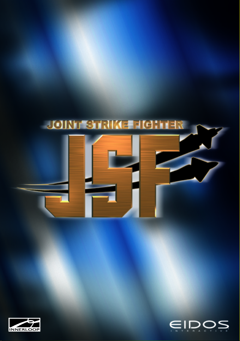
Main Menu
General
After the intro and the title screen, the first
s c reen presented when you run Joint
Strike Fighter is the Main Menu, shown in
the screen below.
The Main Menu
The Dogfight Menu
The Dogfight menu allows you to set up and
fly a combat mission in any of the wa r
t h e a t res included in the Campaign version
of Joint Strike Fighter. If this is your first
time playing the game, we recommend
you use Dogfight to learn how the planes
handle in combat and to become familiar
with the in-flight game commands. Refer to
section 4 for details on how to jump into the
c o ckpit and plunge directly into the action.
The Campaign Menu
Accessing the Campaign menu enables you
to start playing on the war theatres. Here all
your missions are planned using the
s e c retly acquired intelligence data and the
line between success and failure is dra w n .
Experience in Dogfighting is pre f e r re d
b e f o re starting on the campaigns. Refer to
Section 5 for more detailed information on
the workings of the campaign mode of JSF.
The Multiplayer Menu
On the multiplayer menu you can team up
with up to 8 other human players over
various network protocols. Use the
M u l t i p l a ye r > C reate Game menu to
configure your own multiplayer game or
choose an existing game from the
Multiplayer menu. Decide your team colour
and teammates in the Game Lobby and
play the game in any of the 4 war theatres
available in JSF. Please refer to Section 6
for the complete description on how to
configure your multiplayer games.
Quit
This selection will quit the game and return
to Windows. Choosing this will save all
settings and player data.
Select Pilot
This option allows you to create new pilots
or select previously created ones for
play. It also displays the cumulative career
score for each pilot, allowing you to judge
your progress in the campaigns. This is
discussed in detail overleaf.
Options
The Options command provides access to
the game control and viewing options. A
detailed description of these options are
given below.
Select Pilot Menu
General
By pressing Select Pilot on the main menu,y o u
a re taken to the Select Pilot Menu. This menu
13
Page 16

a l l ows you to cre a t e, modify or delete pilots.
The select Pilot screen has been clicked
and the Edit Pilot screen is shown
Creating A New Pilot
Press New on the pilot screen to create a
new pilot. Click on the Name box to
change your name, and the Call Sign box
to change your call sign. Assign the pilot
an aircraft, either the Boeing X-32 or the
Lockheed Martin X-35.
Selecting A Pilot
C l i ck on a call sign on the Duty Roster to
select a pilot. That call sign is highlighted in
ye l l ow and is now considered the active pilot.
Deleting A Pilot
In order to delete a pilot, first select your
choice by clicking on the Duty Roster.After
the selection is made, click the Delete
button at the lower left of the screen.
You will be asked to confirm the deletion;
click on Yes to complete the deletion or No
to return to the Select Pilot menu without
deleting the pilot.
Viewing Pilot History
In addition to name, callsign and pre f e r re d
p l a n e, all pilots have a history where all
a chievements are re c o rded. This is accessed
by selecting Stats on the pilot screen. Use
the arrow buttons to cycle through the
d i f f e rent scenarios to see how the pilot has
p e r f o rmed on the different campaigns.
Resetting Pilot History
If a campaign has turned from bad to wo r s e,
and disaster seems certain, you might feel
l i ke starting ov e r. This can be done by
p ressing Stats in the pilot scre e n ,and then
c l i cking on Reset Scenario. You’ll be aske d
to confirm that you really want to reset the
scenario - click Yes to perform the reset or
No to re t u rn to the Select Pilot scre e n
without clearing the history.
View Information Movies
Details on the JSF program, the weapons
systems and the selected airc raft are
available in FMV format. These movies can
be played by clicking on one of the three
film icons in the lower right of the screen.
The Options Menu
General
The options menu really consists of three
different screens: the game menu, the
graphics menu and the sound menu. From
these three menus,you can use the mouse
to activate or deactiva t e, adjust or
reconfigure various settings of Joint Strike
Fighter. Most elements are also available
from the in-game menus. Each of the
screens are described below.
Tip : Players using slower computers are
encouraged to adjust terrain, object and
14
Page 17

graphical details features of the game to
achieve optimal performance during flight.
The Game Configuration Screen
General
benefit of learning new skills and
maneuvers from the more ex p e r i e n c e d
pilots. As they advance through the skill
l e v e l s ,they learn more maneuvers,d e v e l o p
better gunnery and bombing skills and
become more willing to use both in combat.
Aces are wily, c rafty opponents, t h e
s u rvivors and victors of many aerial
combat missions; they should not be
u n d e restimated. They know all the
standard air combat maneuvers and aren’t
afraid to use them at any time, and have
The Options menu with the Game tab selected
also developed excellent gunnery skills.
The Game Screen is where you are able to
configure how the game behaves during
play.The following items are available:
Input Device
This item simply lets you select whether to
play using keyboard, mouse or joystick.
Further configuration must be done from
the in-game menu, or alternatively (for
basic hard wa re installation) in the W i n d ow s
Control Panel.
Enemy Skill
This option sets the skill rating of the pilots
you and your wingmen will be flying
against. Select one of five (5) settings:
Rookie, Novice, Average, Veteran and Ace.
The default setting is Av e ra g e, with
Rookie the easiest type of enemy pilot to
fight against and Ace the hardest.
Rookies know only basic flight skills;
they’ve been rushed to the front straight
from training school. They haven’t had the
Remember, you may be a match for the
Aces in the game, but your wingmen may
not be so skilled. Think carefully before
selecting the Ace opponent skill, or you
may find yourself going through
wingmen by the bushel. Commanding
officers have been known to take a dim
view of flight leaders who continually
come home as the sole survivor of a
mission. Besides, who wants to write a lot
of letters that begin with the sentence,
“We regret to inform you…”?
Start On Runway
This allows you to start the mission with
your aircraft ready on the runway, without
the need for taxiing.
Easy Aiming
This is a toggle-option. When selected,
your plane’s cannon lead sight will be in
Easy Aiming mode.
You won’t have to think much about
15
Page 18
leading the locked target; the cannon
rounds will actually lead themselves and
try to ‘chase’ the target. This is not a
guaranteed, automatic hit; however, the
closer the locked target is to the centre of
your aiming sight,the better the chance of
a hit with this option selected.
Most pilots would look at you like you
were from another planet if you used
anything else than feet and knots to
m e a s u re distances and speeds
respectively. Check this box, however, if
you are a novice and find the metric
system easier to get the hang of.
When not selected, cannon rounds will
behave using the normal laws of physics.
This will result in a wonderful aerial
display of tracer lights but far fewer
gunnery kills.
Easy Landings
When toggled on, your undercarriage can
t a ke more of a beating, making it
significantly easier to land.
No Wind
Though not obvious when cruising at high
a l t i t u d e s , a strong wind may prov e
problematic during landings and takeoffs.
When this option is checked,your plane is
not affected by wind and weather.
No Fadeouts
When this option is selected, pilots won’t
experience red-outs or black-outs when
pulling extreme G-forces in combat due to
tight turns, dives or climbs.
No Turbulence
Even with no wind, hugging the terrain at
low altitudes makes for a bumpy ride.
Checking this box will disable low-level
turbulence.
Measurement System
Network Protocol
This option allows you to select which
n e t work protocol to use. The most common
protocols are IPX and T C P / I P, but the game
will take advantage of the Mplayer system
and any protocol supported by Direct Play.
Refer to Appendix 3 for details.
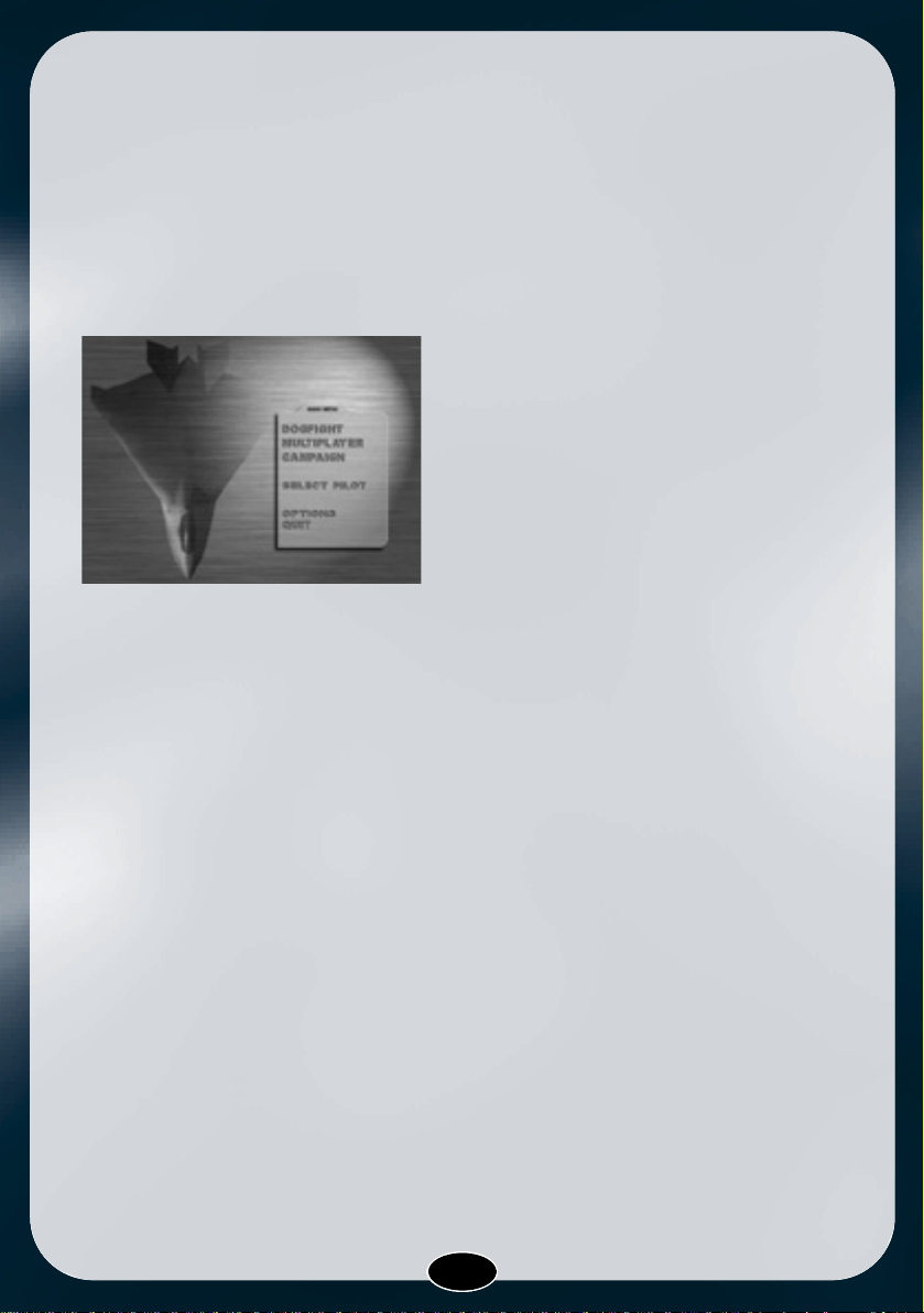
The Graphics Configuration Screen
General
The Options menu
with the Graphics tab selected
This screen allows you to configure how
the game looks during play. Configuring
these options can dramatically change the
performance of the game, so you are
strongly encouraged to play around with
different settings until you determine what
is right for you. The following items
are available:
16
Page 19

Screen Resolution
This option allows the player click left or
right to select screen resolution from the
list available on the computer. T h e
available modes may va ry between
d i f f e rent mach i n e s , from as low as
320x200 pixels (lo-res) to super- h i - re s
(1280x1024 or higher) and everything
in-between. How e v e r, p l a yers using
computers with slower processors may
experience some jerkiness when game
graphics are set at the higher resolutions.
We recommend experimenting with the
lower resolutions until you find the one
that performs best for you.
Big Pixels
If you want to run the game in lowresolution modes, and your gra p h i c s
card/driver does not support this, JSF can
emulate low - resolution by re d ra w i n g
using big pixels. This means that the game
is redrawn in low-resolution internally,and
then doubled to fit the physical screen
resolution. This option is not available in
modes less that 640x400.
Black Lines
If the Big Pixels option is enabled, the
Black Lines option lets you select how the
scaling of the screen is performed. When
checked, every other line is not redrawn,
but left black. This is slightly faster than
the alternative, when all lines are drawn.
Screen Pageflip
(This is one for those familiar with the
inner workings of their PC. You may need
to play around with this option in order to
get the best possible results.)
Internally,the game is able to render both
to System Ram or (if enough memory is
available) to Video Ram. Enabling Page
Flipping may increase your frame rate on
computers with relatively fast graphics
cards; on the other hand, performance
may suffer if your graphics card is
relatively slow.
Object Detail
This slider adjusts the relative amount of
polygons used for rendering the 3D
objects in the game. Moving the slider to
the right increases detail, but possibly at
the expense of performance.
Terrain Detail
This slider works in a similar way as the
object detail slider, only this adjusts the
detail level on the terrain. Moving the
slider to the right will increase the
definition of the landscape and increase
the number of ground objects,but again at
the expense of refresh rate. Keeping this
value around the centre is recommended.
Transparent Smoke
When checked, this option improves the
a p p e a rance of the smoke - t rails in the
17
Page 20

game by using transparency. Performance
may suffer on slower computers.
Transparent Shadows
When this box is checked, shadows are
projected onto the ground with tra n s p a re n cy, rather than as single colour
silhouettes.
Transparent Explosions
Using transparent explosions will improve
realism, but can be a serious performance
hit. Keep this in mind if you are
experiencing slow d own when viewing
large explosions.
Lensflares
L e n s f l a res emulate the optical effect
created by a camera when exposed to
strong light sources, for instance from the
sun or a rocket blast. When checked,these
effects are enabled. Disabling the effects
will, however, improve performance.
Particles
When enabled, a particle system is used
for rendering weather effects like wind
and rain. This may reduce performance on
slower computers.
3Dfx
H a rd wa re rendering is enabled by
ch e cking this box. By default, 3 D f x
acceleration is enabled if a 3Dfx card is
detected in the computer. If no card is
detected,this item is inactive.
The Sound Configuration Screen
The Options menu with the Sound tab selected
Sound Effects
Most actions performed in flight, such as
firing a weapon and raising the landing
gear, have sound effects that play when
the action is performed. This box enables
such sound effects.
Sound Volume
When sound effects are enabled, t h i s
slider adjusts the volume of the sound
effects.
Music
JSF features several original music tracks
that play during flight. This check-box
determines whether music is played.
Music Volume
If music is enabled in the item above, the
music volume can be adjusted here using
the slider.
18
Page 21

Speech
In-game speech is enabled by default, as
this is one of your primary sources of
information. It can, however, be disabled
by unchecking this box. Note that this
makes you totally rely on text messages
for such things as radio communication
and flight computer messages.
Speech Volume
When speech is enabled, this slider
determines the volume of the speech.
Reverse Stereo
On some computers, the placement of the
l o u d s p e a kers are ex changed. Check i n g
this box reverses this.
Mute
When checked, all sound (sound effects,
music and speech) are turned off.
19
Page 22

SECTION FOUR
DOGFIGHT: GETTING STARTED FAST
20
Page 23

General
Selecting Main Menu>Dogfight takes you
to the Dogfight Settings menu. T h e
Dogfight option allows you to hone your
skill in the noble art of dogfighting,
something which will come in handy as
you progress through the campaigns.
You’ll be able to challenge increasingly
more difficult enemies in the different
scenarios in a variety of different settings.
These parameters are described below.
By clicking on this item, you’ll be able to
select in which weather condition you
wish the fight to take place. Different
regions on the globe have differe n t
weather types, w h i ch means that the
available options will vary from scenario
to scenario.
Guns Only
This option disables Air to Air missiles in
the Dogfight session. Though not strictly
realistic, it makes for some interesting
aerial duels in the true spirit of the great
aces of WWI and WWII.
Scenario
H e re you set the theatre in which the dogfight
t a kes place. Not only do the enemy airc ra f t
become increasingly more capable on the
later scenarios, the enemy pilots are also
m o re skillful,a g gressive and lethal.
The Dogfight Menu
In order to customise the Dogfight session
you have a set of four options which
determine the combat conditions:
Time Of Day
This option lets you decide at what time
during the day the dogfight will take place.
While the enemy may be easily seen at
d a y - t i m e, you may have to resort to
systems like night vision and the synthetic
object overlay when battling it out at night.
Weather
Playing
When you start the Dogfight session, you
start out against a wave containing just
one single enemy plane. If you destroy this
first plane, your weapons are replenished
and a new wave appears.
For every wave destroyed another plane is
a d d e d , t h e re by giving an increasing
difficulty level. This is further enhanced by
the fact that, as time progre s s e s , t h e
enemy planes also are of increasingly
better types. The dogfight session ends
when you eventually are killed or when
you decide to leave the session.
21
Page 24
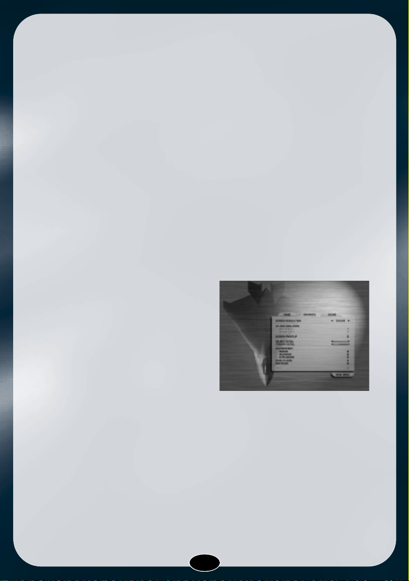
Statistics
When the Dogfight session is ov e r, a
statistics screen appears that lets you
c o m p a re your dogfight performance to
your previous merits and your ow n
personal best. By comparing with old
records, you’ll soon see progress as you
develop the dogfighting skills needed to
succeed when taking on the campaign
game.
Dogfight Statistics
22
Page 25

SECTION FIVE
Flying a Campaign
23
Page 26

General
While an individual mission has specific
tactical goals (the destruction of a convoy
or interdicting airspace over an enemy
t a rg e t , for ex a m p l e ) , a campaign is a
series of individual missions designed to
a chieve one or more long-term or
strategic goals. Take the air battle in the
Gulf War, for instance: One of the major
strategic goals of the campaign was to
hurt Iraq’s air and ground forces badly,
making it easier to drive Iraq’s army out of
Kuwait and, in the process, save Allied
Force’s lives. To this end, thousands of
individual air missions were launched to
bomb ground units, shoot Iraq’s air force
out of the sky and destroy command and
communications links.
In a JSF campaign, you are given similar
strategic goals, based on one of the four
hypothetical campaign scenarios included
with the game. As a wing commander,
your job is to plan and execute a series of
tactical missions to help achieve the
campaign’s strategic goals. You accomplish these goals by destroying all the
primary targets indicated in the mission
planner.The object category is determined
by a higher command.
The Campaign menu.
Select your campaign to start or re-enter
Starting A Campaign
1.To begin a new campaign or enter one in
p r o gre s s , select Campaign from the
Main Menu. The War Theatre selection
screen will appear.At any time you may
select the Back button at the bottom
right of each screen to return to the one
previously displayed.
2.Highlight either one of the four
scenarios using the mouse or the
keyboard. In the box at the bottom of the
screen a brief background story and a
mission summary will appear, relevant
for your current selection. Activate the
scenario by clicking the mouse or hitting
enter.
3.The first time you activate a scenario the
complete mission text will be printed to
the screen. You may speedup the text by
hitting enter, space or by clicking the
m o u s e. After loading, the Mission
Planner will appear.
24
Page 27
The Mission Planner
General
As a wing commander your main objective
is to plan the best possible campaign for
you and your wingmen so the main
s t rategic goal can be re a ched with a
minimum of casualties. This means you
will have to plan your missions carefully
before getting airborne. All planning is
done prior to take-off in the Mission
Planner, which loads automatically when
you select a scenario.
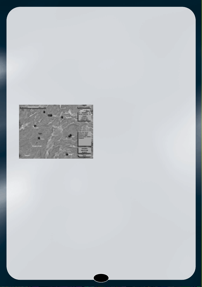
The main Mission Planner screen
The Mission Planner is essentially a
topographical map indicating the position
of anything essential and important for
planning a mission. This includes cities,
factories, airports and roads (in grey), but
most importantly all friendly installations
and enemy targets indicated by the
c o l o u red icons. The icons pinpoint all
enemy, friendly and civilian/non-combat
ground and air units in your area of
operations.
The planner operates in two differe n t
modes: Edit and Map mode. In Editing
mode you can manually or automatically
form a mission by creating waypoints and
selecting targets. Map mode allows you to
manipulate the map information displayed
in the mission planner, this is detailed in
the section entitled Mission Planner Usage
below.
Mission Planner Map
General
The Mission Planner map is a topographical map displaying the curre n t
situation in the activated scenario.
All enemy targets and friendly installations
are displayed using several different icons
and colour codes. The position of each
icon is altered according to the movement
of the unit as the game progresses. If the
unit is destroyed you will be notified and
the icon will be removed from the mission
planner.
Together with the icons marking the
targets you will also see the waypoints
and flight path displayed on the map. A
waypoint is a position used by the flight
computer for navigation placed in the
mission planner prior to take-off. For more
i n f o rmation on how to manipulate
wa y p o i n t s , refer to the section below
entitled Mission Planner Usage.
Icons
Each icon on the map marks an enemy
unit. This means an icon usually
symbolises more then one target. The icon
position is the centre position of all the
objects included in that particular group.
Each icon is colour coded, indicating the
25
Page 28

object category. On the mission map you
may find icons with the following colours:
red, green and blue. Any red icon is an
enemy target and should be considered as
a potential threat. Both the green (neutral)
and the blue (allied) symbolise friendly
icons. Destroying these will have a
negative impact on your statistics.
When you look on the mission map you
may notice a red circle centred on some of
the icons. The red border is a Surface-toAir Missile Engagement Zone (SAM MEZ).
When flying within this zone,you and your
wingmen are subject to being detected
and fired upon by enemy SAM
installations.
Fighter/Bomber
Helicopter
Air Transport
AWAC Aircraft
Airport
Military Base
Military Camp
Factory
Nuclear Facility
Harbour
Radar Installation
SAM/AA Installation
Oil platform
Warship
Cargo Vessel
Submarine
Transport
Infantry Vehicle
SAM/AA Vehicle.
Waypoints
Waypoints are fixed three dimensional
positions (longitude, latitude and altitude)
used by the flight computer for navigation.
They are easily created with the mouse or
automatically with the Suggest option
when in editing mode. Read more about
waypoints and the their usage under the
section Mission Planner Usage.
Mission Planner Windows
General
The Mission Planner Windows contains all
the text, buttons and bars displayed in the
mission planner. They may be hidden by
selecting the button in the upper right
c o rner labelled Mission Planner or by
tapping the spacebar. Use this when
planning a mission if any icons are
concealed by the mission planner
i n f o rmation text and the buttons.
N o t e :While any pop-up window is activa t e d
the Mission Planner W i n d ows will be
disabled and the buttons, bars and tex t -
26
Page 29

boxes will be changed in intensity. to get
focus back to the windows you have to
close the active window.
Planner Manager Window
General
The Planner Manager is the window in the
upper right corn e r, b e l ow the Mission
Planner caption or button. The manager has
t wo tab dialogs which decides which state
or mode the planner currently has active.
Edit Mode
General
To get in Edit Mode you select the Edit tab
dialog from the Manager Window. When
you are in editing mode you can create
and alter your waypoint path by changing
the position and height of your waypoints.
The waypoints are uploaded to the onboard computer upon takeoff and used for
navigation by the autopilot.
Suggest
The Suggest option will automatically
suggest the closest visible primary target.
If no primary icons are displayed the
nearest secondary target will be selected.
If you are not content with the target
selected you may cycle all targets with the
arrows left and right of the Suggest label.
In Map Mode you may select which icons
will appear on screen by checking the
corresponding options, refer to the Map
Mode section below for details.
Terrain following
If you enable the Terrain following option
the suggested waypoints will be forced to
the minimum height for low-level contour
flying, keeping the fighter below radar. If
no waypoint path or target have been
p reviously suggested,enabling or disabling
this option will automatically select a
target and suggest a path.
Clear
Selecting Clear will delete all waypoints
and target selections from the mission
planner.
Statistics Window
From the Edit menu selecting Statistics
will display the current scenario statistics.
Select the Done button to close the
Statistics Window.
Target Info Mode
When you click on this option the Mission
Planner enters Ta rget Info Mode. T h e
change of state is indicated with a
question mark in the lower right of the
mouse pointer. In addition all the icons
with target information visible in the
Mission Planner Map are highlighted.
Selecting a highlighted icon from the map
will display the relevant target information
with the corresponding photos and images
made available by Mission Control. You
may close the window by selecting Done
at the bottom right corner of the window.
At any time you can return to normal
planner operation by clicking the right
27
Page 30

mouse button or just by selecting any
function from the Mission Planner
Windows.
Tip: When in editing mode, pressing and
holding the CTRL key will activate the
Target Info Mode. It will remain active until
the key is released or you exit Target Info
Mode as mentioned above.
Map Mode
General
To get in Map Mode you select the Map tab
on the Manager Window. When this is
selected you will see on the Map menu a
list of options divided into three groups:
Object category, target class and map
settings. Checking any of these settings
will influence the information that appears
on the Mission Map.
Object category
Only the targets that match any of the
checked priorities will be displayed. This
means if you only ch e ck the primary
option, only the primary targets will be
displayed.
Target Class
There are three different target classes
and only the icons containing objects of
the selected class will be displayed.
When you plan a mission you might want
to focus only on airborne targets. To do
this, you would only check the air option
and leave the ground and mobile blank.
Map Settings
General
The Map Settings are useful feature s
when planning a mission. Both the SAM
MEZ and the names option are checked by
default.
SAM MEZ
If the SAM MEZ is checked the missile
engagement zone will be displayed. Use
the MEZ to avoid unnecessary contact
with SAM sites on your way to the
designated target.
Names
When the names option is checked the city
and area names will be plotted on the
Mission Map.
Grid
The grid is useful for calculating distances
when planning a mission, but maybe most
importantly for easier tra cking of the
enemies movements. The grid scale is
5400 NM.
Time Skip Window
In the upper left corner is the Time Skip
bar indicating which scenario has been
activated,the current day and the scenario
time.When selecting this bar a dialog box
will be displaye d , giving you the
opportunity to skip a maximum of eight
hours at once to avoid bad weather and/or
night flying conditions.
28
Page 31

Wingmen Window
In addition to the two JSF contenders, the
F-22 Raptor is also scheduled to be in
active service at the time when the action
in Joint Strike Fighter takes place. Your
wingmen will always have the option to fly
any of the three aircraft,at your discretion.
You’ll need to select which plane your
wingmen will be flying, and whether to
optimize the payload for stealth or mission
effectiveness. This is done from the
Wingmen Menu.
The Wingmen Window
To activate and use the menu:Click on the
Wingmen option in the box at the lower
right hand corner of your screen. The
Wingman menu will be activated.
Click on the arrows next to each wingman
to set his aircraft. Click on the Force Same
Aircraft box if you want all three wingmen
to use the same aircraft at all times.
Under the Weapons Load section,click the
radio button next to either Maximise
Stealth or Maximise Payload. If you choose
Maximise Payload,every hard point on the
aircraft will carry either a bomb or missile.
However,this will make it easier for enemy
radar to detect the aircraft. Selecting
Maximise Stealth reduces the payload,but
makes it much harder for the aircraft to be
detected.
When you’re finished, c l i ck the Done
button.
Now you’re ready to check the aircraft
payload and, if you wish, change the
weapons your airc raft will carry into
battle.
The Arm Plane Window
Arm Plane Window
Beside the cannon, there are a variety of
Air-To-Air (A2A) and Air-To-Ground (A2G)
missiles and bombs that can be carried by
the JSF. Choosing the right payload to
complete the mission is vital; cluster
bombs are effective against mobile units,
but JDAM are more effective against fixed
targets.
The game will automatically select a
payload configuration that includes both
A2A and A2G weapons. However, you may
h ave your own pre f e rences on what
weapon best completes the mission; the
Arm Plane menu allows you to check and
alter this configuration before flight to suit
your needs and preferences.
29
Page 32

In the previous screen, you can see the
A rm Plane W i n d ow with the curre n t
weapon configuration shown on the
graphical re p resentation of the fighter.
There are eight hard points on the JSF;
four of which are internal attach points.
Except for the rocket pod, which may only
be fitted on the wings, most weapons
available can be fixed to any hardpoint on
the aircraft.
The weapons are shown to the right,
divided into Missiles and Bombs. To see a
description of the weapon and its
c a p a b i l i t i e s , simply move the mouse
pointer over the weapon; the description
will appear in the text box at the bottom of
the screen. See also Appendix 5:Weapons,
for full descriptions.
Drag-and-drop Weapon Selection
The Arm Plane Window functions as a drag
and drop editing box. To arm the plane
with a missile, simply select the weapon
with the pointer before draging it and
place it on any of the hardpoint on the
image to the left.
When you drag a weapon to a hardpoint
a l re a dy holding a weapon, the new
selection will replace the former. If you
drop a weapon anywhere other than a
hardpoint, the selection will be discarded.
Changing The Default Weapons
Configuration
You may carry any or all of the weapons
in the game, limited only by the carrying
capacity of the aircraft and its number
of hard points.
To add a weapon to an empty hard point
or swap out the current weapon for a
new one, do one of the following:
• Move the mouse pointer over one of the
weapon icons in the right-hand list;
• Left-click and hold down the mouse
button;
• D rag the weapon to the desire d
hard point;
• Release the left mouse button. The
weapon is now loaded onto the hard
point.
To add or subtract fuel from the aircraft:
Locate the Fuel load gauge, located
under the aircraft silhouette;
• Click on the black arrow icons to the left
and right of the gauge to subtract or add
fuel to the aircraft.
• Removing fuel from the aircraft will not
allow you to put more ordnance on the
a i rc raft. It will, h ow e v e r, m a ke the
aircraft more agile in flight, giving it an
advantage in combat.
• The selected configuration will be
automatically saved for future use. You
can go back to the default configuration
by clicking on the Default button at the
bottom left of the screen.
When you’re re a dy to jump in the
cockpit and fly the mission, click Done.
30
Page 33

Campaign Statistics Window
To view your overall campaign statistics
from the Mission Planner, click on the
Statistics button. When you’re finished
examining the stats,click Done to return to
the Mission Planner.
The Mission Planner Statistics screen
Mission Planner Usage
Planning A MIssion
Planning missions is quick and easy. It
involves a five step process:
1.Decide on one or more targets;
2.Plan and select flight waypoints;
3.Choose which aircraft your wing will fly;
4.Arm the aircraft;
5.Fly the mission.
There are four clickable windows to assist
you in these tasks, accessed from the
Planner Manager Window on the righthand side of the screen. Detailed
i n f o rmation about both these window s
and their functions are given in the section
above entitled Mission Planner Windows.
Selecting A Target
To plan a mission,first locate your take-off
position. Your plane is indicated on the
map by a blue plane icon surrounded by a
green circle.The green circle indicates the
Base or waypoint 0 and cannot be
re m oved. After you have successfully
located your fighter it’s time to select a
target.
Though the primary targets should be your
first concern, any enemy unit should be
c o n s i d e red a threat. All red icons are
hostile, so selecting any of these are fine
for a mission. But if you want to focus on
campaign progress you might want to
select only primary targets. This is easily
done by clicking Suggest from the Edit
menu. A l t e rn a t i v e l y, ch e ck the primary
object category checkbox from the Map
menu. This allows you to locate and
identify just the primary targets for better
mission planning.
When selecting targets you should
consider the target composition. If the
target is only lightly protected, you might
want to leave some wingmen behind.
Getting Information On Enemy Targets
While you may plan a mission to any target
in the Mission Planner, Headquarters will
have designated priority targets that they
wish attacked. You cannot complete the
Campaign until you’ve destroyed all of
primary targets.
With the CTRL key held down or while
selecting Target Info from the Edit menu,
certain targets will be highlighted on the
31
Page 34

Mission Map. Intelligence inform a t i o n
about these targets, including information
on the weapons and installations in the
target area is available by clicking on it’s
icon. This information can be crucial in
planning what payload to carry on an
a t t a ck mission. Rare l y, if ever, w i l l
intelligence information be available on
non-priority targets.
Target Info screen showing
information on a priority target
To see the intelligence information about a
priority target:
1.Click on Target Info, on the Edit Menu;
2.Left click on one of the priority targets
on the Map;
3.The Info screen will appear. When
you’re finished,click on the Done button
to return to the Mission Planner.
4.You may also right-click when no Info
screen is displayed to cancel the Target
Info command and return to the Mission
Planner.
Once you have decided which target you’ll
be attacking for the mission, it’s time to
plan a route to it.
Planning A Route To The Target
General
It’s important to remember that the JSF is
designed to be stealthy. Not only is it built
using stealth technology (which gives it a
greater reduced radar signature ) , it is
designed to be able to sneak into a target
at very low altitudes, using terra i n
features to help hide the aircraft from
enemy radar. To this end, it has a new
version of the terra i n - f o l l owing ra d a r /
autopilot electronics package. When the
aircraft is placed on autopilot, it uses the
o n b o a rd Te r rain Following Radar to
maintain a low altitude and steer itself
around terrain obstacles.
Your objective as a wing commander
should be to plan a route to the target that
takes advantage of the surrounding terrain
as much as possible.
32
The Suggest button has been clicked
Page 35

Generating Waypoints To The Target:
The Suggest Option
The Mission Planner has an option to help
you plan a route to priority targets. Here is
how you take advantage of this option:
On the Edit Menu,find the Suggest option.
There are black arrows to the left and right
of the Suggest button. Click on them to
scroll forwa rd and back through the
current list of priority targets.
As you click to scroll through the targets,
the Mission Planner suggests a route both
to the target and back to your Base. These
routes are denoted with a bright green
line,interspersed with bright green boxes.
The boxes are the actual waypoints which
the plane will fly towards. Each waypoint
includes altitude information. If you want
them to be terrain following you check this
option, if not the altitude will be set to
32000 ft. All targets which have been
selected will be surrounded by a green
circle, in the same way as your own plane.
To get information about each waypoint
move the pointer over it, and the text will
appear in the text box on the right-side of
the screen.
If you wish to accept this route,you need
do nothing else; move on to the Arming
The Fighter and Wingmen sections below.
Manually Editing Waypoints
General
As a general rule you always add wa y p o i n t s
with the left mouse button and delete with
the right mouse button. you can not edit
waypoints in Map Mode.
Usage
To create your own waypoint, just move
the mouse pointer to the point on the map
where you want the waypoint to appear,
then left-click. You can use this method to
plan your own route to a target, without
using the Suggest option.
Note: All waypoint editing features will
work for both your own created waypoints
and those created by the Suggest option.
If you wish to delete a waypoint,centre the
mouse pointer on the waypoint box and
right-click. The waypoint will disappear
and the Mission Planner will fill in the
route line.
If you wish to move a waypoint,centre the
mouse pointer on a waypoint, then click
and hold down the left mouse button. Now
move the mouse; the waypoint and route
line will move with the pointer. Move the
waypoint to your desired location and
release the left mouse button.
If you wish to alter the height of a
waypoint, just left-click on the waypoint
box to toggle through a range of preset
waypoint altitudes. The height will be
displayed in the textbox.
All waypoints currently on the map can be
cleared by clicking on the Clear menu
option, on the Edit Menu.
Tip: If you press and hold the ALT key,
left-clicking on a waypoint will shift the
altitude between terrain following and the
maximum height.
33
Page 36

Zooming: Getting A More
Detailed Look At The Map
General
If you wish to get a more detailed look at
the map this can easily be done with the
mouse. Select Map mode and left-click to
zoom. The map will be centred around the
mouse pointer. If you want to continue
editing waypoints when the map is
zoomed, you just have to switch back to
Edit mode.
Usage
The first thing you need to do is to select
the Map tab dialog in the upper right
corner of the screen. This will activate
Map mode enabling you to manipulate the
Mission Planner Map. When you are in
Map Mode the mouse pointer will change
to a magnifying glass until you go back to
waypoint editing. Move the cursor to the
point on the map you want to examine and
left-click. The map will zoom in for a
closer look.
To re t u rn to the larger map, l e f t - c l i ck
again. Repeat the procedure for each spot
on the map you wish to examine in more
detail.
When you’re finished, click on the Edit
button to return to Edit Mode for creating
and editing waypoints.
The Mission Planner with the Map tab selected
Flying A Mission
When you’re satisfied with your route and
wa y p o i n t s , weapons load and the
wingmen’s aircraft,it’s time to load up and
fly the mission.
To do this,simply click the Take Off button
in the lower right hand corner of your
screen. The flight simulator will load and
you’ll be in the cockpit of your aircraft,
ready to take off.
Ready for Takeoff!
34
Page 37

General
The very first time you start a campaign
and click on Ta ke Off in the Mission
Planner, your aircraft will not be on the
runway, but nearby on a taxiway. You’ll
need to start your engines, add some
power, brake while on the ground and
steer the aircraft to and turn onto the
runway to takeoff. refer to section 8:Flying
the Plane for details.:
1.Request takeoff permission.
2.Turn on engine and increase to taxi
speed (approx. 15 knots).
3.Taxi to the runway.
4.Extend flaps and go into afterburners.
5.Pull the stick back and when airborne
retract the your gear.
How to taxi and take off
Whenever you start a mission there are
several things you may do to facilitate your
takeoff.
One of the first things you should do is to
radio the tower and ask for take o f f
p e rmission. Doing this the tower will
normally grant you permission to takeoff
and turn on the runway lights. This makes
taxing easier as also the taxiway will
be lit. For more information on how the
radio wo r k s , see Appendix 4: R a d i o
c o m m u n ication.
When you have located the corre c t
taxiway you are ready to increase the
thrust and accelerate to taxing speed and
manoeuvre to the runway:
• To add power to your airc raft and
increase speed,press the 1-9 keys.
• To steer your aircraft, use the rudder
keys, the ‘,’ (comma) key to steer left
and the ‘.’ (period) key to steer right;
• To brake your aircraft and slow down,
use the B key;
Tip: Press F11 for satellite view, using
PageUp and PageDown to zoom in/out.
Steer your aircraft forward and turn onto
the runway, using the brake as needed,
and coming as close to facing down the
centreline stripe as possible. Then use the
rudder keys to turn left or right, facing
d own the runwa y, with the centre l i n e
down the middle of your screen.
Press the CTRL + 0 (zero) key to engage
afterburners. When the speed indicator on
the HMD is at 150 mph or greater,lift back
on the joystick to pitch the nose of the
aircraft up and take off.
Tip: To save the time and trouble of taxiing
out onto the runway each time you fly a
campaign mission, use the ESC key to
activate the in-flight menu while in the
cockpit, then press the Right Arrow key
until the Game menu is highlighted and
press Enter. Then use the Down Arrow key
to highlight Start On Runway and press
Enter again. From now on, all campaign
missions will start on the runway,ready to
start engines and fly without the need to
taxi onto the strip. Press ESC again to
return to the cockpit.
35
Page 38

Getting To The Target
General
The general idea is to manoeuvre your
fighter according to the plan you laid
out in the Mission Planner. This can be
done either manually or by activating the
autopilot.
Autopilot
Once in the air, getting to the target is
pretty easy,if you follow these steps:
1.Gain at least 1000 feet of altitude;
2.Press the A key to activate the Autopilot.
The HMD will display the word WAY
a b ove the altimeter tape; when the
autopilot is set to follow waypoints and
it is activated you can read the word
WAY on the upper left side of the HMD.
3.With the Autopilot activated, the aircraft
will automatically move from waypoint
to waypoint.
4.If you wish to bypass a waypoint, press
the W key to instruct the autopilot to
take you to the next one in the route.
Use the CTRL + W key combination to
cycle backwards to a previous waypoint.
5.When you reach the target, press the A
key to deactivate the autopilot and make
your attack.
NOTE: Your autopilot will never turn itself
off, even if you are bounced by enemy
aircraft. If you are bounced by the enemy,
you need to manually deactivate the
autopilot if you wish to turn and fight.
Manual Approach
When you are airborne you can easily
follow the waypoints manually,but for this
to be feasible make sure the HMD is
t u rned on. Press the Del key on the
numeric keypad to toggle the HMD on /off.
You will be manoeuvring using the
heading tape on the top of the HMD
screen. The bearing (compass direction) of
the currently selected waypoint will be
indicated on the tape by the waypoint
carat pointing in the direction you need to
turn. You should direct the nose directly
towards the carat, which means keeping
the carat at the middle of the screen.
When you have reached the waypoint you
will be notified by the on-board computer,
and you need to activate the next waypoint
by pressing the W.
There are three types of waypoints, which
waypoint you are following can be seen in
the lower right corner of the screen,if you
are heading towards a Engage waypoint it
means you are flying towards a selected
target.
When you have reached your target select
the appropriate weapon and attack.
Note:To see the waypoint information you
have to be in navigation mode; press the N
key to activate Nav mode.
To cycle back wa rds between the wa y p o i n t s
press CTRL + W.
36
Page 39

Attacking Ground Targets
1.Deactivate the autopilot;
2.Use the Backspace key (or the proper
button on your joystick, see Appendix B)
to cycle through your A2G weapons,
until the one you want shows as active
on the HMD.
3.Using the radar and arrow information
on your HMD, manoeuvre your aircraft to
line up on the target.
4.When the target reticle is over the
target or you achieve a target lock,
press the Spacebar to drop the bomb.
Remember The Hatch
When you are ready to attack your target,
you have to prepare your weapon. If an
external weapon have been selected, you
need do nothing more. But if the weapon is
carried inside the fuselage, you will need
to open the hatch.
Remember opening the hatch increases
your radar signature,and should therefore
be done as late as possible during the
attack.
Ending The Mission
General
When you have completed your mission
and returned to your airbase, you are
ready to end your mission. When you have
parked on the tarmac it is time to Quit &
Save.
Go Home!
To return to your base:
1.Activate the autopilot by pressing the
A key;
2.The autopilot will follow the waypoints
to your home base. If you haven’t
planned a return waypoint path,activate
waypoint 0 (zero) to get back to base.
3.When you have re a ched the base
de-activate the Autopilot by pressing A
again;
4.Land the plane on the runway.
The Mission Debriefing
General
When you have finished a mission select
Quit & Save from the in-game menu. You
will exit the game and automatically enter
the Mission Debriefing.
The Mission Debriefing screen will give
you a summary of your mission’s success
or failure. It will include the area map,
with points of action during the mission
shown as small explosion-icons.
Mission Debriefing Map
General
This is the same map as you have seen in
the Mission Planner. This includes all the
icons and additional information displayed
on the Mission Map.The only addition is a
explosion-icon pinpointing the position of
any destroyed objects and a blue line that
shows that path you have flown.
37
Page 40

Flight path
When you are in the mission debriefing
you have the option of displaying your
flight path. If you check the option in the
Manager Window you will see a blue line.
This is the distance cov e red by your
fighter during your mission.
Mission Debriefing Windows
General
Note: While any window is activated the
debriefer will be disabled and the buttons,
bars and textboxes will be changed in
i n t e n s i t y. To get focus back to the
debriefer you have to close the Statistics
window,
Scenario Bar
The scenario bar indicates the scenario
progress. If everything is the way it should
be,and your game is progressing normally
the only text printed in the scenario bar
will be Scenario Progress. If you on the
other hand have for some reason failed,
and the scenario is lost you will be notified
in the scenario bar – in addition to the
information screen that will be displayed
when you exit the Mission Debriefing.
Debrief Manager Window
In the Debreif Manager Window you may
select the information you want displayed
on the Mission Map.
The options are similar to the Map menu,
refer to the Mission Planner W i n d ow s
paragraph above,except for the additional
options: Flight Path and Waypoints. To see
your flight path or waypoints, you select
the corresponding checkbox.
Statistics Window
To get the overall statistics of the mission,
click the Statistics button. This window
lists several details regarding your last
mission; such as flying time,the number of
allied and enemy object destroyed and
weapons in percentage.
When you are done reading the statistics
you close the window by selecting the
Done button in the lower right corner of
the statistics screen.
The Mission Debriefing Statistics window
Progress Bar
The progress bar is located in the bottom
left corner of the screen. This is where the
game status will be printed. If you have
failed completing the scenario or you have
successfully finished the campaign the
text will change accordingly.
If everything is normal and no special
cases have occurred the text will read
“Scenario Progress”.
38
Page 41

Mission Debriefing - General
Move the mouse pointer over any of the
explosion icons to see a brief action description of what was destroyed and when
it occurred.
Using The Debrief Manager Window
Exiting Mission Debriefing
After ending a mission the debreifing is
automatically loaded. On the mission map
you will be presented with a mission
summary. When you are done studying it
and you are ready to move on,the mission
planner will be loaded and your plane
prepared for your next mission.
To exit the mission debriefing click the
Mission Planner button in the lower right
corner.
Continuing a Campaign
When you exit the Mission Debriefing your
plane will be pre p a red and the game
p r o gress saved. The campaign will
automatically continue from where you
left off.
Note:The game progress does not include
waypoints or target selections, w h i ch
means all waypoints will be lost when you
quit the Mission Planner.
39
Page 42

SECTION SIX
Multiplayer Dogfight
40
Page 43

General
The JSF Multiplayer Dogfight option allows
you to go head to head with up to eight
players at the same time. In this section
you’ll find out how to start or join a
network game and how the game behaves
when started. A closer description of the
individual network protocols can be found
in Section 3.
Starting your own game
The following steps need to be undertaken
in order to start your own multi-player
game:
1. Choose the protocol you wish to use on
the Options>Game menu, and then
continue to the Multiplayer menu by
selecting the Multiplayer item on the
Main Menu.
Multiplayer Menu
3. The Multiplayer>Create Game menu
contains five options that allows you to
modify the default multiplayer game:
• Time Of Day:Allows you to change the
hour at which the multiplayer game
takes place. Using the late hours of the
day decreases the possibility of visual
detection, which will force players to
fly and tra ck using instruments instead.
• Weather:Switches between the different weather conditions. Note that the
different theatres have different types
of weather e. g. :S n ow, rain and clear.
• Number Of Kills: This options selects
the duration of the game. You can
choose from a list of 5, 10,15, 20, 25,
30 or UNLIMITED. If UNLIMITED is
selected, the game will last until the
last player leaves the game. Otherwise
the game will continue until a player or
a team has re a ched the selected
number of kills.
• Guns Only: Enabling Guns Only will
remove the Air to Air missiles from the
multiplayer game.
• Theatre: Lets you choose the theatre
to use for your multiplayer game.
Choosing between the different
scenarios also changes the weather,
thus increasing the difficulty of flying
on scenarios with demanding weather
conditions.
2. On the Multiplayer menu select the
Create item. This activates the Create
Game menu.
Multiplayer Create Game Menu
41
Page 44

4. After adjusting the multiplayer game to
your needs, select Start to create the
multiplayer game and proceed to the
Game Lobby.
Joining an existing game
1. Choose the protocol you wish to use on
the Options>Game menu, and then
continue to the multiplayer menu by
selecting the Multiplayer item on the
Main Menu.
2. On the Multiplayer menu select the
Refresh item, this will, after a while
display a list of active games in the
Games in progress window. Each
game has its own title (e.g. “JSF Game created by Snapper”) and also
displays the number of free slots for
new players. For more information on
a multiplayer game, highlight a
specific game. This will make a more
specific description (including a
t h e a t re, weather and time of day)
appear in the Game information
window.
3. Now just select the active game you
want to join,and you will automatically
proceed to the Game Lobby menu.
Rules of play
General
When you’re spawned in the game, you
start of with a set amount of weapons and
about two minutes of fuel (at 90% thrust).
The rules of the game are described below.
Team Score
The score of a team is counted as the
average of kills achieved by each team
member. This means that playing in a big
team is not necessarily an advantage, as
players who do not contribute significantly
will lower the team average.
Duration Of The Game
Depending on the settings selected by the
host of a network game, the play may
continue indefinitely (when unlimited kills
a re selected) or until one team has
achieved the selected number of kills. At
this time, the game fre e z e s , and the
statistics screen (described below) is
shown.
Replenishing Fuel And Ammo
When blasting away at your opponents,
you’ll soon find your fuel and ammo
running low. T h e re are two ways to
replenish these:
Fly through a reset point: In each theatre
there is an object suspended in the air
close to your starting position. Flying
through it gives you fuel and weapons,
but leaves you vulnerable while
approaching.
Land at a nearby airbase:Close to the area
where the multiplayer game takes place,
there is an airbase which can be used for
replenishing your plane. This also leaves
you extremely vulnerable while approaching the landing strip, so it should be
42
Page 45

attempted only as a last resort when you
are out of fuel.
player has died.
The Game Lobby
Multiplayer Lobby
When you enter the Game Lobby you’ll
see a window that displays the active
p l a yers in the multiplayer game. T h e
window shows all the information about
you, the highlighted player, and the other
players. The player information is split
into five groups:
• Team: Each player is initially given
their own team displayed as a colourbar in the team colour. Selecting your
own colour-bar will result in a team
ch a n g e, w h e reas selecting another
player’s colour-bar will join the team
of that player. NOTE: The player who’s
team you joined,might change his own
team. So you’ll have to re-select his
colour-bar to rejoin his team.
• P l a ye r : Displays the call-sign
identifying the player.
• K i l l s : Displays the kill count of
the player.
• D e a t h s : Tells how many times the
• S t a t u s : This indicates the players’
states in the game (i.e. Playing, Dead
or Loading).
Just below the Players Window is a status
bar which displays your status in the
m u l t i p l a yer game. T h e re are thre e
different states, as follows:
• Waiting for server re s p o n s e : This
means that you haven’t been accepted
in the game yet. Don’t worry if this
takes a while - if for instance the
G a m e S e rver is busy loading, no
p l a yers will be accepted until it’s
finished loading.
• R e a dy to go: The GameServer has
accepted you as a participant of the
game, and you can now select Go to
start playing.
• Game over: This means that a team or
a player has reached the number of
kills set by the game host. All you can
do is to leave the game and find
another game to join.
After attaining Ready To Go and having
selected your team colour, simply select
Go to start the game.
43
Page 46

Statistics
General
When playing you are able to view the
advancement of the players by using the
statistics screen. JSF has two different
statistics screens that can be used during
a multiplayer game:
Multiplayer Statistics
Simple Statistics
If enabled,this displays a horizontal list of
the different team colours. The team
values are listed so that the team with the
highest average of kills is shown first.
same as on the Game Lobby (i.e. Playing,
Dead and Loading).To toggle between the
statistics modes press the CAPS LOCK key.
Full Statistics
When using the advanced statistics, the
horizontal list from the simple statistics is
moved to middle of the screen. Below the
list is a spreadsheet containing a list of
players. The players are listed so that the
player from the team with the highest
average is first. Within the team, players
are listed so that the player with most kills
and least deaths are first. Each player
listing show the player name, the player
kills, the player deaths and the status of
the player. The status of the player is the
44
Page 47

SECTION SEVEN
THE IN-FLIGHT MENUS
45
Page 48

General
The in-flight menus are accessible at the
top of the screen at all times while you are
flying. It allows you to change, adjust or
reconfigure basic game options, including
resolution mode, sound volumes, graphic
detail of the terrain, buildings and other
aircraft, enemy skill and more. Most of
these options are also available from
Options on the Main Menu, though the inflight menu also includes a few other
features, such as the ability to accelerate
time to reduce Time to Target.
To access the drop-down menu bar, press
the ESC key,located in the upper left-hand
corner of your keyboard. The menu bar will
appear across the top of your game
screen. The game default is set to pause
flight while the In-Flight menus are active.
The menu is navigated using the arrow
keys, and features can be selected by
pressing Enter. To close the in-flight menu
and re t u rn to active flight, p ress ESC
again.
The seven submenu sections of the
Dogfight in-flight menu are:
Mission
Allows you to restart the mission, quit the
mission or save your progress.
Dogfight
Allows you to restart or quit the game
Network
A l l ows you to quit the network game
Game
Set up time compression, Gameplay and
menu options.
Cheats
Allows you to cheat by simplifying certain
aspects of the game.
Difficulty
Allows you to select the skill level of
your opponents
View
Camera and External view options.
Campaign In-Flight Menu bar
Controls
Select plane flight control methods and
alter/adjust options for them.
Mode
Select graphics modes and re s o l u t i o n
options.
46
Page 49

Graphics
Change terrain and transparency details.
Sound
Volume and stereo options.
Help
Display ke y b o a rd commands and game cre d i t s .
Please note that some of these sub-menus
are only available in certain play modes
(dogfight, campaign or network dogfight).
This is described in greater detail below.
mission planner. If you’re flying a campaign and select Quit, you’ll have to plan
your mission again from the start.
Quit & Save
You may select Quit & Save at anytime
from the in-game menu; when you do,you
will enter the Mission Debriefing screen.
When you exit the mission debriefing
s c re e n , one hour will be added for
preparing the aircraft for the next mission.
If the mission is a success and you return
to a friendly base with your aircraft, no
additional penalties of any kind will occur.
Mission
This sub-menu is only available when
playing a campaign. When you select the
Mission menu, you have access to three
options: Restart,Quit and Quit & Save.
Restart
This option cancels the current mission
and reloads it from scratch: your mission
is restarted as if you had just left the
mission planner. All of your mission
waypoints are uploaded to the flight
computer and the scenario time is rolled
back to your current mission’s initial time.
When you select Restart, no penalties of
any kind are imposed, even if you have
c rashed or been killed; you will lose
neither a fighter nor a pilot. It also means
that any targets destroyed during your
current flight will be not be scored.
Quit
Selecting Quit takes you back to the
This is not the case if you quit and save
before reaching a friendly base. In this
case,you’ll lose an aircraft and,unless you
eject and return to a friendly base on foot,
you will lose a pilot, as well. In other
words,try to get as close to a friendly base
as possible before bailing out, in order to
reduce the distance you’ll have to cover on
foot and the chances of losing a pilot.
Mission In-Flight Menu
Dogfight
This menu is only available when you are
playing dogfight. It gives you access to
items: Restart and Quit.
Dogfight In-Flight Menu
Restart
This option quits and restarts a new
dogfight game with your current settings.
47
Page 50

Quit
Selecting Quit takes you back to the
Dogfight main menu screen. You’ll be able
to alter the Dogfight settings and relaunch
into a new set of attack waves.
Network
The network menu is only available when
you are playing multiplayer dogfight.
There’s only one item:
s e t t i n g. This means that every t h i n g
happens at twice its normal speed.
Normal x3
Triple the compression of the Norm a l
setting,thereby making everything happen
at three times normal speed.
Normal x4
Sets four times the compression of the
N o rmal setting, effectively making
everything happen at four times normal
speed.
Network In-Flight Menu
Quit
This selection quits the network game and
returns you to the lobby.
Game
T h e re are three sub-menus you can alter in
this menu,Time Factor,Gameplay and Menus.
Game In-Flight Menu.
Time Factor
This allows you to use time compression to
speed up the action. T h e re are four selections:
Normal
The default, which means that there is no
time compression.
Normal x2
Double the time scale of the norm a l
N o rm a l l y, time compression is only
desired in campaign mode. Please note
that due to the complexity of the
simulation, the processor may not always
be able to run the game internally at the
requested time factor.This may result in a
lower framerate and jerky graphics.
Gameplay
There is one option under Gameplay, Start
On Runway.This toggle option is only used
in the Campaign games, though it can be
t u rned on and off at any time. W h e n
checked, all campaign missions start with
the aircraft out on the runway instead of in
a taxi area. This saves you the time and
trouble of taxing to the runway before
each Campaign mission.
Menus
There is one option under Menus, Pause
Game. When selected, pressing ESC to
a c t i vate the in-flight menus will also
pause the game. When not selected, your
48
Page 51

aircraft continues in flight,even when you
are checking the in-flight menus.
Cheats
These options are intended to make
missions easier to fly and increase your
chances of survival. They are divided into
the following categories:
Cheats In-Flight Menu
View
This has just one customizable item:
No Fadeouts
When selected, pilots won’t experience
red- or blackouts of the field of view when
pulling extreme G-forces in combat due to
tight turns, dives or climbs.
Physics
Here you are able to simplify a few options
w h i ch affect the way physics are
simulated in the game:
problematic during landings and takeoffs.
When this option is checked,your plane is
not affected by wind and weather.
No Turbulence
Even with no wind, hugging the terrain at
low altitudes makes for a bumpy ride.
Checking this box will disable low-level
turbulence.
Cannon
This section determines the behaviour of
your gunshots. It has just one item:
Easy Aiming
This is a toggle-option. When selected,
your plane’s cannon lead sight will be in
Easy Aiming mode. You won’t have to think
much about leading the locked target; the
cannon rounds will actually lead
themselves and try to ‘chase’ the target.
This is not a guaranteed automatic hit
however, the closer the locked target is to
the centre of your aiming sight, the better
the chance of a hit with this option
selected.
When not selected, cannon rounds will
conform to the normal laws of physics.
This will result in a wonderful aerial
display of tracer lights but far fewer
gunnery kills.
Easy Landings
When the checkbox is toggled on, the
undercarriage can take more of a beating,
making it significantly easier to land.
No Wind
Though not obvious when cruising at high
a l t i t u d e s , a strong wind may prov e
Damage Level
This section determines which amount of
damage applied to your plane. There are
t wo selections possible in this menu,
Realistic and Invulnerable. When Realistic
is checked, your aircraft can take only a
certain amount of damage and survive;
modern warfare being what it is,that ain’t
49
Page 52

much.
N o t e : Selecting ‘ I n v u l n e rable’ disables
your ability to save your progress in the
campaigns.
Supplies
This section consist of a single item:
Unlimited Ammo
When this option is selected, you’ll never
run out of missiles, bombs or cannon
rounds.
Note : Unlimited Ammo also disables your
ability to save your progress.
Difficulty
Enemy Skill
This menu is only available in campaign
play. It allows you to set the skill rating of
the pilots you and your wingmen will be
flying against. Select one of five settings:
Rookie, Novice, Average, Veteran and Ace.
The default setting is Average, with Rookie
the easiest type of enemy pilot to fight
against and Ace the hardest.
benefit of learning new skills and
manoeuvres from the more experienced
pilots. As they advance through the skill
l e v e l s , they learn more manoeuvre s ,
develop better gunnery and bombing skills
and become more willing to use both in
combat.
Aces are wily, c rafty opponents, t h e
s u rvivors and victors of many aerial
combat missions; they should not be
u n d e restimated. They know all the
standard air combat maneuvers and aren’t
afraid to use them at any time, and have
also developed excellent gunnery skills.
View
This menu is designed to allow the player
to customize certain view options and has
two sections: Camera and View.
View In-Flight Menu
Camera
There are two options deciding how the
camera in the game behaves:
Difficulty In-Flight Menu
Rookies know only basic flight skills;
they’ve been rushed to the front straight
from training school. They haven’t had the
No Shaking
Normally, the camera shakes slightly at
high velocities and during tight G-turns.
When checked, this options turns such
shaking off.
No Head Tilting
When this option is checked, the camera
won’t show the pilot’s head experiencing
50
Page 53

tilts due to G-forces during maneuvers.
View
This sub-menu allows you to configure
whether or not flight information is superimposed on the screen. It has three sections:
a i rc raft controls are to your ke y b o a rd input.
HMD Radars
When ch e cke d ,the active and passive ra d a r
displays from the MFDs are superimposed
on the lower corners of the HMD.
External HMD
When selected,portions of the HMD will be
available to certain external views.
Enable Messages
When selected, this displays tex t
messages that complement the computer
and radio messages into the cock p i t .
Examples of such messages are “Enemy
Lock-On” and “Shoot”
Controls
This sub-menu is used for configuring the
input to the game. In addition to the basic
choice of whether to use keyboard,mouse
or joystick, it also presents a contextsensitive section that allows you to
configure each device:
Keyboard
When keyboard is selected, the controls
menu also shows the following item:
Keyboard Sensitivity
This slider adjusts how responsive the
Controls In-Flight Menu with keyboard input device selected
Mouse
When playing with a mouse, the controls
menu contains the following items:
Controls In-Flight Menu with mouse input device selected
Pitch Sensitivity
This slider adjusts how responsive the
aircraft controls are to movement along
the y-axis.
Roll Sensitivity
As abov e, but this slider adjusts the
responsiveness along the x-axis.
Inertia
This slider determines how much inertia
there is in the mouse controls.
Button Remapping
Here you have two displays. The upper line
shows which button to edit (left, right or -
51
Page 54

if playing with a three button mouse - the
centre button). The lower line shows what
function is currently assigned to that
button. Selecting the upper line and
pressing Enter changes which button to
edit, doing the same on the lower line
changes the function. Using CTRL toggles
the opposite direction.
to raise it.
Rudder Sensitivity
Works in the same manner as XY
Sensitivity above, with the aircraft rudder
becoming more or less sensitive
to commands.
Joystick
When keyboard is selected, the controls
menu also shows the following items:
Controls In-Flight Menu with joystick input device selected
Centre
When selected and the ENTER ke y
pressed, this option pulls the joystick and
reassigns the centre vector for the stick’s
current position.
XY Sensitivity
This is a gradient bar that raises or low e r s
the XY coordinate sensitivity to flight
m a n o e u v re commands. The higher the sens i t i v i t y, the quicker the airc raft will re s p o n d
to XY coordinate changes during flight.
To alter this setting, highlight the XY
Sensitivity option and press the ENTER
key. Then use the left arrow key to lower
the sensitivity and the right arrow ke y
To alter this setting, highlight the Rudder
Sensitivity option and press the ENTER
key. Then use the left arrow key to lower
the sensitivity and the right arrow key to
raise it.
Slack
On many joy s t i ck s , the input is never
completely zero, even when the
joystick seems to be in the centre position.
Normally, this could cause the aircraft to
pitch and roll slightly, even when no force
is used on the joystick. The slack slider
can be used to define how much tolerance
is to be used around the neutral position.
To alter this setting, highlight the Slack
option and press the ENTER key. Then use
the left arrow key to lower the slack and
the right arrow key to add to it.
Force Feedback
If you have a Force Feedback joystick
attached to your computer, this option
allows you to select whether or not it
should be enabled. Check the box to turn
Force Feedback on.
If no Force Feedback joystick is selected in
the Windows Control Panel, this option is
52
Page 55

greyed out.
Button Mapping
This works exactly like the mouse button
mapping described above, only here you
are able to select the function of each
button on your joystick. The upper line
shows which button to edit (Fire 1, Fire
2 , e t c.). The lower line shows what
function is currently assigned to that
button. Selecting the upper line and
pressing Enter changes which button to
edit, doing the same on the lower line
changes the function. Using CTRL toggles
the opposite direction.
Mode
This menu allows you to select which
screen resolution to use when playing the
game. It contains three items:
H ow e v e r, p l a yers using computers with
s l ower processors may experience some
jerkiness when game graphics are set at the
higher resolutions. We recommend ex p e rimenting with the lower resolutions until
you find the one that performs best for you.
Lo-Res Emulation
This is short for Low Resolution Emulation,
and features two options:
Big Pixels
If you want to run the game in lowresolution modes, and your gra p h i c s
card/driver does not support this, JSF can
emulate low - resolution by re d ra w i n g
using big pixels. This means that the game
is redrawn in low-resolution internally ,and
then doubled to fit the physical screen
resolution. This option is not available in
modes less that 640x400.
Mode In-Flight Menu
Screen Resolution
This option allows the player to select
screen resolution from the list available on
the computer. This may va ry between
d i f f e rent mach i n e s , from as low as
320x200 pixels (lo-res) to super- h i - re s
(1280x1024 or higher) and everything in
between. To select a new screen resol u t i o n , use the Up/Down arrows to
highlight the desired resolution,then press
the ENTER key.
Black lines
If the Big Pixels option is enabled, the
Black Lines option lets you select how the
scaling of the screen is performed. When
checked, every other line is not redrawn,
but left black. This is slightly faster than
the alternative, when all lines are drawn.
Graphics
This menu offers submenus which allow
you to change object and terrain complex i t y
Graphics In-Flight Menu
53
Page 56

to enhance performance, select certain
graphics features in the game and add or
remove some transparency effects during
flight. Note that subtracting detail and
features will enhance performance at the
expense of visual appearance.
Detail
This section lets you add to or subtracts
from the graphic detail of objects, such as
a i rc ra f t , and terrain feature s , s u ch as
buildings and roads. It is divided in two:
Object Complexity
A gradient bar that adds or subtracts detail
from objects you see during flight,such as
other aircraft. To alter the current setting,
use the Up/Down arrow keys to highlight
the selection and press Enter. Then use the
Left/Right arrow keys to va ry the
gradient bar setting. Moving the bar to the
right will add complexity; move it to the
left to subtract detail.
Terrain Complexity
This slider works in the same manner as
Object Complex i t y. Use the Left/Right arrow
keys to add or subtract from terrain detail.
Terrain Objects
This slider detemines how many terrain
objects should be drawn-none, only the
trees,or all terrain objects.
Features
The graphics engine of Joint Strike Fighter
contains a number of effects and features
which enhance the graphics, yet are not
vital to the gameplay. These can be
enabled or disabled in this and the
following sub-menu.
Enable Lens Flares
Lens flares emulate the optical effect
created by a camera when exposed to
strong light sources, for instance from the
sun or a rocket blast. When checked,these
effects are enabled. Disabling the effects
will improve performance.
Enable Particles
When enabled, a particle system is used
for rendering weather effects like wind
and rain. This may reduce performance on
slower computers.
Transparency
Certain special effects in the game can be
rendered with or without transparency.
Though tra n s p a re n cy may reduce the
performance of the game, it may add to
the visual appearance of the game. The
following effects are handled separately:
Smoke
When checked, this option improves the
a p p e a rance of the smoke - t rails in the
game by using transparency. Performance
may suffer on slower computers.
Shadows
When this box is checked, shadows are
projected onto the ground with tra n s p a re n cy, rather than as single colour
54
Page 57

silhouettes.
Explosions
Using tra n s p a rent explosions will improv e
re a l i s m , but can be a serious perform a n c e
hit. Keep this in mind if you are ex p e - r i e n c i n g
s l ow d own when viewing large ex p l o s i o n s .
N OT E : We highly recommend you ex p e riment with the options in the in-flight
d r o p d own menu, especially those playing
JSF on computers with pro-cessors slow e r
than a 166 megahertz Pentium. A d j u s t i n g
the options in Graphics and Mode to display
less object and terrain detail at lower re s o l u tions can dramatically increase the perf o rmance of the game on these computers.
highlighting the option, pressing Enter to
activate it, then using the Left/Right arrow
keys to decrease or increase the volume.
Sound Effects
Most actions performed in flight, such as
firing a weapon and raising the landing
gear, have sound effects that play when
the action is performed. Set your desired
volume level of the in-game sound effects
by highlighting the option, pressing Enter
to active it,then using the Left/Right arrow
keys to decrease or increase the volume.
Speech
This slider raises or lowers the volume on
speech messages to you during flight. This
applies both to radio messages and the
VOCOM.
Sound
The sound menu allows you to configure
how music, sound effects and speech are
played back through your loudspeakers. It
contains the following sections:
Sound In-Flight Menu
Volume Control
Music Track
JSF features several original music tracks
that play during flight. Set your desired
volume level of the in-game music by
Stereo
Reverse Channels
On some computers, the placement of the
l o u d s p e a kers are ex changed. Check i n g
this box reverses this.
Enable Messages
In-game speech is enabled by default, as
this is one of your primary sources of
information. It can, however, be disabled
be unchecking this box. Note that this
makes you totally reliant on text messages
for such things as radio communication
and flight computer messages.
Master Volume
This submenu has only one item:
Mute
55
Page 58

When checked, all sound in the game is
disabled.
Help
This menu is intended to offer you
keyboard help, as well as give access to
the About Box and the credits list. It
contains the following commands:
Help In-Flight Menu
Keys
Activating this option will display a screen
listing the flight keyboard commands. Use
[Up] and [Down] to scroll between pages.
To return to the in-flight menu, press ESC.
About
Activating this option will display a screen
with information on the developer and
publisher. Pressing ESC will return you to
the in-flight menu.
Credits
A c t i vating this option will display a
series of scrolling screens showing who
contributed during the development of
Joint Strike Fighter. Press ESC to return to
the in-flight menu.
56
Page 59

SECTION EIGHT
Flying the Plane
57
Page 60

General
This section is intended to teach you the
ins and outs of the Joint Strike Fighter
planes. By reading this part you’ll not only
get familiar with the flight behaviour of the
JSF planes; you’ll also get a deeper
understanding of the underlying systems
of the aircraft. This includes the Flight
Assistance Systems, Avionics Suites,
Automated Defence Systems and your
virtual cockpit environment.
If you find this too much information to
digest in one go, you can always refer to
this section later for technical details of
the aircraft. Still, it’s well worth the effort
try to get an overview of what’s going on
“behind the scenes” as you ride through
the sky.
Flight Handling
Operating the Engine
To start your engines and power up the
aircraft, press the [~] key, located in the
upper left of your keyboard, directly below
ESC (or next to return).
Taxing on the Ground
A speed of about 15 knots is usually
convenient when taxiing on the airport.
This is most easily achieved by applying a
short burst of power to the engines, and
then using the inertia of the plane to keep
you rolling. The B key can be used to slow
down your airplane if you go too fast.
To steer your aircraft, use the rudder keys
[<] and [>] to steer left and right. Steer
your aircraft forward and turn onto the
runway, using the brake as needed, and
coming as close to facing down the
centreline stripe as possible. Then use the
rudder keys to turn left or right, facing
d own the runwa y, with the centre l i n e
down the middle of your screen.
TIP 1: To save the time and trouble of
taxing out onto the runway each time you
fly a campaign mission,check the Start On
Runway option on the in-flight menu. From
now on, all campaign missions will start
on the runway, ready to start engines and
fly without the need to taxi onto the strip.
To add power to your aircraft and increase
speed, press the 1-0 keys, with 0 being
100% power and 1 being 64% power. To
turn the engine off press CTRL and [~].
See also Appendix 1 for a complete list of
all keyboard commands, and Appendix 2
for a description of joystick and gamepad
configuration.
TIP 2:Throttle control is the key to taxing.
Be careful to not go too fast during turns.
Takeoff
Press the zero, 0, key to push your thrust
to 100%. When the speed indicator on the
HMD is at approximately 150 mph or
greater, pull the joystick back to tilt the
nose of the aircraft and take off. Once
in the air,press G to retract the gear.
58
Page 61

In-Flight Operations Hatch
To use the weapons in the intern a l
weapons stations, you’ll need to open the
h a t ch. This is done with the H ke y.
Remember that having the hatch open
increases your radar cross section - so
don’t forget to close it after you have
delivered your weapon load.
Airbrake
The air brake or speed brake slows the
plane down by increasing drag. Holding
the B key down while you are in the air
achieves this by elevating a moveable
surface on the top rear of the aircraft.
Flaps
Use the flaps to gain extra lift during
takeoffs. They are turned on and off with
the F key. Remember that having the flaps
out increases drag, so retract them once
you have gained your desired speed.
Gear
Be sure to retract your gear after take-off
so you don’t damage your undercarriage.
Having the gear down while airborne also
increases drag on the plane.Take the gear
in and out with the G key.
keys and W at the same time. T h i s
command will first jettison ex t e rn a l
weapons, and if you invoke it a second
time it will jettison your internal weapons.
You can also jettison fuel - this is activated
by pressing both CTRL keys and J at the
same time. Fuel jettison is turned off again
by pressing the key combination once
m o re. Note: A l ways ch e ck your fuel
storage,fuel consumption and distance to
nearest friendly airport before invoking
this command.
Eject
When all hope of returning to base is lost,
you may want to consider ejecting from
the plane. This is done by pressing both
CTRL keys and E at the same times. Note,
however,that this is not without risk.
Landing
Landing should be performed at
approximately 135 kt (250 km/h),
depending on weapons load. Fully loaded,
you may have to land slightly faster,while
a virtually empty plane will allow you to
land with reduced air speed.
Jettison
If you for some reason need to reduce your
weight during flight you have two options:
Jettison Fuel or Jettison Weapons.
If you need to reduce your radar signature
or reduce your weight press both CTRL
HMD with correct landing angle
59
Page 62

The key to a successful landing is
achieving the correct speed and Angle Of
Attack (AOA). The AOA display is intended
to help you judge your AOA at any time. It
shows angles from 11° - 15°, and for
ideal landing the velocity vector should be
placed in the centre of this (i.e. at 13°). In
addition, the velocity vector should be
placed approximately 4° below the horizon
for a perfect in-flight landing path.
TIP: If you are a rookie pilot be sure to
enable Easy Landings on the in-flight
menu. This will make it harder to get
wheel damage when touching down
Flight Assistance Systems
General
Autopilot
Almost all modern aircraft are equipped
with an autopilot (a computer able to fly
the aircraft). To activate the JSF’s autopilot, press A. To deactivate its autopilot,
p ress A again. The complete autopilot
system is available on the Control MFD /
AUT, and operates in 4 different modes.
You can alter the data used by the
autopilot, such as heading, height, speed,
according to the situation requirements.
Mode 1: Waypoint
In waypoint mode, the autopilot directs
your aircraft to the active waypoint, with
the selected height and speed. Useful
when you want to study the MFDs,fly with
accelerated time or just to enjoy the view.
Mode 2: Heading
When selecting heading mode, t h e
autopilot maintains the selected heading,
at the selected height and speed.
Aircraft systems overview.
In today’s combat environments, p i l o t s
experience enormous pressure and huge
workloads. They must at all times
maintain high situational awareness while
c o m m u n i c a t i n g, monitoring airc ra f t
systems,monitoring and evading missiles,
positioning their aircraft, etc. Research on
easing pilot workload has resulted in a
number of sophisticated Flight Assistance
Systems, all present in the JSF aircraft.
Mode 3: Tracking
The tracking mode maintains the speed of
the active air target. Perfect for lining up a
cannon kill, or if you want to maintain a
constant distance from a target.
Mode 4: Auto-Throttle
The auto-throttle mode helps the aircraft
maintain a constant speed. This is
selected by the pilot on Control MFD / AUT.
Perfect for situations requiring constant
speed, like landing and dogfights.
60
Page 63

Terrain Avoidance System
Too many deaths of fighter pilots are not
the cause of an enemy missile,but of their
own inattention leading to an encounter
with a hard surface - like the ground. This
has especially been the case when flying
at low altitudes. The designers of the X-32
and the X-35 therefore decided to include
a Te r rain Avoidance System in their
planes. This system continually monitors
the state of the aircraft, and adjusts the
direction of the plane if there is a Crash
Situation.
While using the autopilot in wa y p o i n t
mode,the avoidance system is always on.
This ensures that you will not crash while
s t u dying your MFD’s. In all the other
autopilot modes and when the autopilot is
off the terrain avoidance state can be set
in the Control MFD / AUT / TRA.
Note: The Terrain Avoidance System is
automatically turned off when you extend
the landing gear.
Terrain Following Box
Sometimes it is preferable to fly terrain
hogging without using the autopilot. In
such a case you should take your gear in,
turn off the terrain avoidance system, and
a small box, called terrain following box,
will appear on the HMD. If you keep your
velocity vector inside this box you will fly
safe at low altitude.
You can adjust the height of the terrain
following box on the Control MFD / AUT /
TRA up and down, as you can for terrain
following waypoints. The recommended
terrain following height depends on what
kind of mission you are on,the terrain and
how many wingmen who join your flight.
Level Function
If you lose control over your plane, press
the level button to recover your flight. Your
flight computer will then level your plane,
and ensure that you gain speed if
n e c e s s a ry. Level operation will cancel
when you touch the throttle or stick. You
can also cancel the operation by pressing
the level button again. The level function is
invoked with the L-button.
Terrain following box
Avionics
General
JSF features a very sophisticated avionics
suite; all combined into an internal suite of
sensors and processors performing a wide
range of different tasks. These tasks
include the active radar, FLIR, SLS, GPS,
IFDL amongst others.
61
Page 64

Active Radar
The JSF aircraft features a long-range
doppler radar able to detect and track
multiple air targets simultaneously. On the
Attack MFD / RAD, you will find a wide
range of functions for operating the radar,
like turning the radar on/off, changing
targets, ranging, target information, view
modes etc.
Ranging
You can select among four different radar
settings:
Range: Cone:
54nm 20º
22nm 40º
13nm 80º
6.7nm 160º
Radar in plan view mode
The Normal Plan View
The normal plan view is the conventional,
easy to interpret view. You will normally
want to use this view mode.
Radar ranges.
View Modes
The radar cone can sometimes be difficult
to interpret; there f o re the JSF airc ra f t
features three different view modes to
select from on the Attack MFD / RAD:
Radar in side elevation view mode
Side Elevation View
The side elevation view is useful for
checking relative altitudes of different air
targets.
62
Page 65

Radar in cross-section view mode
Cross Section View
If you want to determine enemy altitude
and movement across your flight path,you
should select this view mode.
Forward Looking Infra-Red (FLIR)
The JSF aircraft is capable of detecting
and tracking vehicles and other moving
objects from which it can obtain an IRsignature. The FLIR is based on the thirdgeneration of ptronic devices, giving it a
360˚ coverage and a range about 20nm. All
FLIR targets are projected onto HMD for
easy detection and identification. You can
cycle through all available FLIR targets
and view information about the active FLIR
target on the Offensive MFD / ATG. See the
HMD chapter for more information about
FLIR targets on the HMD.
Global Positioning System (GPS)
The Global Positioning System uses three
or more satellites to calculate the exact
position of the receiver. In this case, the
receiver is the JSF airc ra f t , and it uses the
GPS to pre-designate targets for use with
GPS guided weapons, s u ch as the JDAM
and JSOW. All pre-designated targets are
projected onto the HMD, and the pilot can
a c q u i re information about each GPS targ e t
( I D,ra n g e,E . T. A , e t c.) through the Offensive
MFD / AT G. See the HMD chapter for more
i n f o rmation about GPS targets on the HMD.
Anti-Radiation Targeting System (ARTS)
The Anti-Radiation Target System is able to
mark the position of radiating systems
within detection range, primarily for use
with the AGM88c HARM weapon. The ARST
works in conjunction with the Radar
Warning Receiver (RWR - see the chapter
Systems for more information). T h e
positions of the radiating systems are
projected onto the HMD for easy
localisation and targ e t i n g. To acquire
information about the Anti-Radiation (AR)
targets, you follow the same procedure as
with FLIR and GPS targets.
In-Flight Data Link (IFDL)
The In-Flight Data Link is a communication
system primarily used to re c e i v e
information about the threat-picture from
a nearby AWACS or your wingmen. This
allows the JSF to minimise the use of its
own active radar, and therefore operate
more stealthily. You establish the IFDL by
communicating with the AWACS (see the
Radio Communications chapter for more
information). The status of your IFDL can
be viewed on the Offensive MFD.
63
Page 66

Satellite Landing System (SLS)
HMD with SLSactive
The SLS can be activated by setting the
HMD in SLS mode (by pressing S) when in
the vicinity of an airport. A landing path is
then projected in 3D onto the HMD. The SLS
is completely passive; it relies only on pre d e t e rmined coordinates that have been
g a t h e red from satellite data in adva n c e.
This means that an airport may be
controlled by the enemy, even if SLS data is
ava i l a b l e. When an airport has not been
verified as safe, the SLS path is displayed in
re d ,rather than the normal gre e n .
Altimeter
Up to altitudes of 5,000ft above the
gr o u n d , the altimeter displays ra d a r
altitude. Basically it uses a small radar to
calculate your real altitude above the
ground. The altimeter automatically
switches to barometric altitude when the
altitude above ground exceeds 5,000ft.
Barometric altitude means the aircraft’s
altitude above sea level. The altimeter is
located on the HMD.
Automated Defence Systems
General
The Joint Strike Fighter is equipped with
sophisticated automated defence systems.
The purpose of the systems are to take care
of the defensive parts - detecting and av o i d ing enemy fire - as far as possible, w h i l e
l e aving the pilot free for offensive opera t i o n s .
Decoys
A decoy is a false target created to fool an
enemy tracking the plane. The decoys
h ave similar reflectivity to the targ e t ,
though usually a bit stronger and more
attractive. Decoys come in two flavours:
Radar decoys
Your plane is equipped with radar decoys
called chaff. Chaff, also known as duppel
or window, are small metallised plastic
strips, which reflects one half of the radar
wavelength. The best moment to release
chaff is when the radar is trying to
establish a lock on the target.
Infra-Red decoys
Flares are pyrotechnical packages that
emit intense heat designed to confuse
Infra-Red missiles.
64
Plane releasing flares
Page 67

Radar Warning Receiver (RWR)
The Radar Wa rning Receiver (RWR)
detects signals from enemy and friendly
radar’s. Its reading is displayed on the
sensor radar (Offensive MFD). The receiver
in the JFS aircraft compares the signals it
receives with a database of know n
signals, and decides if the emitter is an
aircraft,missile or ground unit.
Infra-Red Warning Receiver (IRWR)
The Infra-Red Warning Receiver (IRWR)
works similarly to the RWR but it detects
IR emitting sources instead of ra d a r
emitting sources.
The core of the IRWR is an Advanced
Distributed Aperture System (ADAS). This
system consists of multiple sensors under
the skin of the JSF, designed to detect
short range ground-to-air missiles, longrange A2A targets and long range
A2G missiles.
Identification Friend or Foe (IFF)
The radar depends on the IFF system to
determine if an aircraft is enemy, friendly
or neutral. The system has two phases;
first the IFF interrogator unit sends a radio
message containing a coded enquiry that
essentially requests friendly planes to
identify themselves. Equipment carried by
the friendly plane,called IFF transponders,
automatically responds to this re q u e s t
with a coded message, which in turn is
picked up by your plane and fed into
your onboard computer. A positive reply
allows your onboard computer to classify
the plane as friendly or civilian.
Electronic Counter Measures (ECM)
ECM is a wide description, defined as
methods to confuse the enemy’s usage of
the electromagnetic spectrum. In this
context ECM is a device that receives
enemy radar signals (ECM receiver unit),
and then retransmits them with a slight
delay (ECM transmitter unit). The result is
that the enemy pick up false signals and
are unable to track you reliably.
Defence Subsystem (DSS)
To ease the stress on the pilot during
d o g f i g h t , the Defence Sub-System (DSS)
was developed. This system automates the
release of chaff and flares. It monitors tra ck ing data and calculates the right re l e a s e
moment. You should normally have the DSS
a c t i vated at all times,as it is effective and
economical in terms of chaff and flare
u s a g e. The pilot can still release chaff and
f l a res manually when the DSS is on.
Cockpit Environment
Multi-Function Displays (MFD)
Cockpit view of all MFDs
65
Page 68

General
The cockpit is fitted with six (6) different
MFD panels; each designed to display
easily and coherently information about
the current state of your airc raft and
mission. They also allow you to alter some
of that information to meet the dynamic
needs of an ever- changing combat
environment.
You can make selections and alter data on
the MFD panels by holding down the Alt
key to activate the mouse pointer. Then
click on the green buttons next to the
selections,around the edge of each panel.
Tip: The MFD panels can be viewed while
the game is paused. However, you cannot
m a ke button selections or alter any
information until you the game is out of
pause mode.
current damage (displayed in a range of
colours from green to red), information
about payload (including jettison controls
and fuel consumption), RCS (radar crosssection) and IRCS (infra - red crosssection),(including a list of conditions that
affect the RCS and IRCS).
Information MFD
The Information MFD includes information
and functions for navigation (including
waypoint selection, time to next waypoint,
range,etc.) and activating/deactivating the
Satellite Landing System (SLS).
Attack MFD
The Attack MFD is mainly the active radar
panel where you can sort through and
select from local, close-in threats and
targets. See the Radar chapter for more
details.
B e l ow are some general explanations
of the various panels and functions of
the MFD.
Control MFD
The Control MFD provides the means to
operate your HMD, including turning on
and off night vision, a c t i vating and
deactivating the HMD and altering autopilot data.
Status MFD
The Status MFD displays a host of critical
i n f o rmation about the status of your
aircraft. This includes general avionics,
Strategic MFD
Navigating by map is mainly done from the
Strategic MFD, which can also overlay the
Offensive MFD display (including wa y points and targets).
Offensive MFD
The Offensive MFD is mainly a display of
the information from the differe n t
defensive systems, the IFDL and the
navigation system. It also allows cycling
through and selecting A i r- To - G r o u n d
targets obtained by the FLIR, RWR and the
GPS.
66
Page 69

MFD Functions
General
E a ch MFD has an on/off button located in
the top left corn e r, labelled “MFD”. Next to
the “ M F D ” button (top row) there may be
one or several Mode Buttons. A c t i vating a
mode button will activate the rest of the
buttons associated with that mode.
Note:In all cases of On or Off toggles while
viewing an option in the MFD panels, the
On position is indicated by a white-lined
border around the option.
Control MFD “HMD” (HMD mode)
Control MFD
“HMD”: Toggles HMD on/off.
“IR”: Toggles night vision on/off.
“STO”: Toggles Synthetic Terrain
Overlay on/off.
“SOO”: Toggles Synthetic Object
Overlay on/off.
“LCK”: Toggles lock of heading
tape and pitch ladder.
When locked, the heading
tape and pitch ladder show
the aircraft’s heading
and pitch,not the pilots
view heading and pitch.
“LAD”: Toggles Tapes and Ladders
on/off.
“
HMD COLOUR
” : Toggles HMD colour
upwards/downwards.
“AVI”: Overlays an artificial
horizon with current speed,
heading and height.
Control MFD “AUT” (Auto pilot mode)
Control MFD in Autopilot mode
“AUT” (Autopilot/Flight assistance
systems mode)
“ECM”: Toggles ECM on/off.
“DSS”: Toggles DSS on/off.
“LEV”: Levels the plane
(recovery button).
“TRA HEIGHT”: Increases/decreases terrain
avoidance height.
“TRA”: Toggles terrain avoidance
on/off.
“AVI”: Overlays an artificial horizon
with current speed, heading
and height.
“AUT”: Toggles autopilot on/off.
“AM”: Toggles autopilot mode
(waypoint, heading, tracking,
throttle).
“SEL”: Selects data-entry
(highlighted in white).
“ ”: Increases selected data-entry.
“ ”: D e c reases selected data-entry.
67
Page 70

Status MFD
“AVI”(Avionics mode)
Status MFD Status MFD in Damage mode
““Dam”
(Damage Mode)
“AVI”: Overlays an artificial horizon
with current speed, heading
and height.
“STO”
(Stores mode)
Status MFD in Storage mode
“JFV”: Toggles Emergency
Jettison Fuel on/off.
“JWE”: Emergency Jettison Weapons.
Jettisons first external
weapons and if activated again,
jettisons internal weapons.
“AVI”: Overlays an artificial horizon
with current speed, heading
and height.
“AVI”: Overlays an artificial horizon
with current speed, heading
and height.
“SIG”
(Signature mode)
Status MFD in Signature mode
“AVI”: Overlays an artificial horizon
with current speed,heading
and height.
68
Page 71

Information MFD
“NAV”(Navigation mode)
Attack MFD
“RAD”(Radar mode)
Info MFD
“WAYPOINT”: Increases/decreases active
waypoint.
“NAV”: Selects NAV mode for the HMD.
“SLS”: Selects SLS mode for the HMD
(activates SLS).
“LGT”: Toggles external aircraft
lights on/off.
“AVI”: Overlays an artificial horizon
with current speed, heading
and height.
“ENV”
(Environment mode)
Attack MFD
“RANGE”: Increase/decreases active
radar range.
“TARGET”: Toggle target
upwards/downwards.
“RAD”: Turns active radar on/off.
“ZOOM”: Zooms display in/out.
“VMD”: Toggles radar view mode.
“AVI”: Overlays an artificial horizon
with current speed, heading
and height.
Strategic MFD
“MAP” (Map mode)
“AVI”:
Info MFD in Environment mode
Overlays an artificial horizon
with current speed, heading
and height.
Strategic MFD
“OVL”: Toggles overlay of
Offensive MFD on/off.
69
Page 72

“AVI”: Overlays an artificial
horizon with current speed,
heading and height.
Offensive MFD
“RAD”(Offensive mode)
Offensive MFD
“EWR”: Toggles display of
information from
the IFDL on/off.
“RWR”: Toggles display of RWR
lines on/off.
“GPS”: Toggles display of GPS
targets on/off.
“IR”: Toggles display of FLIR
targets on/off.
“AR”: Toggles display of AR
targets on/off.
“ZOOM”: Zooms display in/out.
“WAY”: Toggles display of
waypoint route on/off.
“AVI”: Overlays an artificial horizon
with current speed, heading
and height.
“ATG”
(Air-To-Ground mode)
Offensive MFD in ATG mode
“ATG”: Toggles ATG-Discriminator
upwards/downwards.
“TARGET”: Toggles ATG target
upwards/downwards.
“GPS RANGE”: Increases/decreases operating
range of GPS targets.
“AVI”: Overlays an artificial horizon
with current speed,heading
and height.
MFD Colour Codes
General
The Attack MFD and the Offensive HMD uses
colour codes for different types of targets
and target categories. The colour code for each
target each target is determined by the IFF
system (see Defensive Systems chapter).
An active target has a yellow outline in addition
to a colour coded square.
Air Targets
Enemy: RED
Friendly: BLUE
Civilian: GREEN
Ground Targets
GPS: PURPLE
FLIR: ORANGE
AR: WHITE
Neutral: GREEN
Missile: YELLOW
Unidentified: WHITE
70
Page 73

Head Mounted Display (HMD)
Tapes and symbols
Heading Tape
The heading tape shows your aircraft’s
current heading and the heading to the
current selected waypoint. If the waypoint
is outside the limits of the heading tape,a
carat will appear either to the left or right
of the HMD marking the direction of the
waypoint.
Forward view from the cockpit in flight,HMD active.
General
Like all modern fighter aircraft, the JSF
features a Head Mounted Display (HMD)
that projects information directly onto the
forward view of the pilot. It provides the
pilot with critical information about his
flight path, speed, altitude, nearby enemy
targets and which of his weapons are
currently active and ready to shoot. This
information is configurable by the pilot; he
can tailor the display to suit his personal
needs and the needs of the mission.
The HMD is perhaps the single most
important source of information you have
available. It can tell you where the threats
are, how many of them there are, the
current state of your aircraft in flight,
weapons status; you name it - it’s there.
You also have the option to superimpose
the Attack MFD and the Offensive MFD on
the HMD for convenience.
Speed Tape
The speed tape shows your airc ra f t ’s
current speed,and the rate of acceleration
is shown by the speed of the tape.
Above the speed tape,the amount of G you
are pulling and the actual thrust of your
engines is displayed.
Altitude Tape
The altitude tape shows your aircraft’s
c u r rent barometric or radar altitude
(indicated by an ‘R’ to the left of the
altitude number).See the Altimeter chapter
for a more thorough description.
The rate of climbing/descending is shown
by the speed of the tape. Displayed above
the altitude tape, are the autopilot mode,
status of brakes, status of flap and the
status of gear.
Pitch Ladder
The pitch ladder shows the pitch (in
degrees) and roll of your aircraft relative to
the horizon.
71
Page 74

Other Symbols
The nose marker marks your current pitch
on the pitch ladder. The velocity vector
s h ows your airc ra f t ’s direction of mov e m e n t .
between you and your target changes. A
positive number means the target is
closing,and a negative number means the
target is moving away from you.
Modes Of Operation
The HMD operates in four different
modes:
NAV (navigation),
SLS (Satellite Landing System),
A2A (Air-To-Air),
A2G (Air-To-Ground).
The current mode is displayed below the
speed tape.
NAV Mode
The NAV mode is used for navigation and it
displays your current waypoint, including
range and estimated time to reach the
waypoint below the altitude tape.
SLS Mode
When in SLS mode, the HMD will display a
secure in-flight corridor as a range of
boxes.
A2A Mode
Below the altitude tape, you can view
information about your current air target,
such as target ID, range and speed.
All targets on your active radar are
projected onto the HMD as bra cke t s
around each target. The active target is
projected as a square with a number under
it. The number indicates Velocity Of
Closure. VOC indicates how fast the gap
Using the target toggle key ([TAB>) in this
mode will cycle through air targ e t s .
Using the target view key ([F12>) in this
mode will view the active air target.
A2G Mode
The A2G mode can operate on three differe n t
types of targ e t s :FLIR (Infra - R e d ) ,GPS (Global
Position System) and AR (Anti-Radiation).
You select the type of targets to operate
with the A2G-Discriminator and it is
displayed to the right of the HMD mode
(only in A2G mode).
All these targets are projected onto the
HMD as different symbols.
All GPS targets are projected as two
carats. The active GPS target is projected
as four carats (forming a marker).
All FLIR targets are projected as brackets
around each target. The active FLIR target
is projected as a rectangle.
All AR targets are projected as crosshairs.
The active AR target is projected as a
crosshair with a square.
Again, below the altitude tape, you can
view information about the current target
determined by the ATG-Discriminator.
72
Page 75

Using the target toggle key ([TAB>) in A2G
mode will cycle through targ e t s
determined by the A2G-Discriminator type.
Using the target view key ([F12>) in A2G
mode will view the active targ e t
determined by the A2G-Discriminator type.
Weapon Sights
Aspect Angle Indicator
The aspect angle indicator is visible on
both the missile and cannon sight circles
as a carat.
The symbology shows the targ e t ’s
HEADING relative to your POSITION. It
indicates what orientation (or side) of the
target aircraft you would see if you were
close enough. The following table
simplifies the situation:
Position of aspect carat on circle:
Aspect of enemy:
weapon you need to open the hatch by
pressing H.
Note: Keep the hatch closed as much as
possible to minimise your radar signature!
Top of the circle Nose
Bottom of the circle Tail
Left side of circle Left wing
Right side of circle Right wing
Hatch Closed Indicator
If you have selected an internal weapon
(i.e. you have no external weapons left),
and the weapons hatch is closed, a hatch
closed indicator as an “X” will appear on
top of the appropriate weapon sight.
B e f o re you can launch / release any
73
Page 76

Cannon Sight
Historical gunsight
The missile sight consists of three parts:
1. A missile boresight circle.
2. An aspect angle indicator.
3. A range indicator,located to the left of
the missile boresight circle, with a
carat indicating range to target relative
to the missiles maximum and minimum
range.
Note: If no carat is visible on the range
indicator, don’t waste your ammo!
The historical cannon sight consists of
three parts:
1. A continuously simulated
bullet trajectory.
2. A range circle positioned at the targets
range along the
simulated trajectory.
3. An aspect angle indicator.
The range circle indicates the range to the
active target. 1 hour equals 1000 feet,so a
full range circle means range to target is
12000 feet.
Missile Sight
Missile sight with target lock indicator
Bomb Sight
Bomb sight
The bombing system is a standard
CCIP (Continuously Calculated Impact
Point) displayed as a straight line from
the velocity vector to the impact-point
(indicated by a small circle at the end
of the line).
If you have the ATG-Discriminator in GPS
mode,and you have an active GPS target,
the weapon system will simulate a glide
trajectory towards the GPS target. If the
glide bomb is able to glide to the target,
the impact point will “snap” to the target
and the probability of a direct hit is
very high.
74
Page 77

Synthetic Overlays
Object Overlay
Synthetic object overlay
The HMD is able to add colour coded
velocity vectors to all targets registered by
the airc ra f t ’s weapon systems (active
radar, FLIR, GPS, AR). In effect, this will
show the movement direction of all targets
in true 3D space. The colour codes are the
same as those used by the Attack MFD and
the Offensive MFD.
Terrain Overlay
synthetic terrain overlay on the HMD.
Basically,the terrain overlay is a computer
generated 3D image of the terrain that
helps the pilot fly the airc raft in
poor visibility.
Night Vision
The HMD has a built-in electro-optical
device that intensifies (amplify) existing
light making it possible for the pilot to see
objects he would not normally see under
poor light conditions (e.g. night). You can
toggle night vision on/off using the Control
MFD.
VOCOM
General
When the on-board computer detects a
situation that is of great importance to the
pilot, it can call attention to the pilot by
displaying text on the HMD or activating
wa rning lights. This is sometimes not
enough to get the pilot’s attention. The
designers therefore put in an another way
of notifying the pilot, called automated
voice computer messages or VOCOM.
The VOCOM is a female voice that tells the
pilot about certain incidents. The VOCOM
is female because research has shown
that this is the voice pilots focus on
easiest.
Synthetic terrain overlay
The JSF carries an onboard terra i n
database; together with information
from other platforms, it can generate a
Warning Tones
When your cockpit is filled with an
annoying “alarm clock” noise, you are in
trouble. The on-board computer uses this
method to get your full attention in an
75
Page 78

emergency situation like when an enemy
is tracking your plane or you are close to
crashing the plane.
Radio Communications
General
The air pioneers in World War I did not
have a radio and had to use hand signals
to communicate. In a modern jet fighter a
UHF radio is taken for granted, and many
o p e rations depend heavily upon it.
The radio com-munications menu is
i n v o ked by holding down Shift.
The menu disappears when Shift is
released. A numbered menu is displayed
in the lower left corner of your screen.
Make selections by continuing to hold
d own the Shift key and pressing the
keyboard number corresponding to the
proper menu item (e.g. Hold the Shift key
down and press 1 to issue orders to All
Wingmen…).
If the menu item is followed by three
periods (…), selecting that item will
display an additional menu of numbered
items.
You have three available radio channels,
one for wingmen, one for AWACS and one
for tower communications. If you issue
many commands at different ra d i o
channels simultaneously, the voice
messages you receive may overlap.
The messages you send will appear on top
of the screen (if text messages are
enabled), and if you have speech enabled
they will be spoken. You will also receive
messages in the same manner. You enable
or disable messages and speech from the
JSF in-game menu.
Tower
The airfield towers are vital to modern air
traffic; so be sure to use it to get safe
takeoff’s and landings.
Use the menu choices Request Landing
Permission, Request Emergency Landing
Permission, Request Takeoff Permission
during takeoffs and landings.
When your plane is damaged, be sure to
use the request emerg e n cy landing
permission. The tower will then reroute
other planes landing,and you will be given
landing permission immediately.
AWACS
The Airborne Warning And Control System
(AWACS) aircraft monitors the battlefield
and reports relevant information to you if
you have an In Flight Data Link (IFDL)
established with the AWACS.This consists
of an encrypted binary data link that feeds
radar information directly into your flight
c o m p u t e r, as well as radio messages
informing you about enemy air activity.
The link is established with the menu
choices Request IFDL and disconnected
with Disconnect IFDL.Giving Orders To Your
Wingmen You can issue a wide variety of
o rders to your three wingmen, e i t h e r
76
Page 79

individually or as a group. Wingmen are
often crucial to your mission, and it takes
a skilled pilot to communicate with them
c o r re c t l y. Be sure to listen to them
carefully,and give the correct response to
their messages and status reports. For a
full explanation of all radio commands
you can issue, see Appendix 4.
For now, we will take you through how to
order them to attack air targets.
Radio communications menu
Ordering The Wingmen To
Attack Air Targets
If you are attacked in flight or the AWACS
gives you a vector to enemy air targets,
you can order your wingmen to attack
them.
4. Select Engage At Will by pressing
the 3 key;
5. Each wingman will now engage any
enemies that come into radar range.
Ordering The Wingmen To
Return To Formation
1. Hold down the Shift key; a numbered
menu will appear in the lower left
corner of the HMD;
2. Continuing to hold down the Shift key,
press the 1 key,All Wingmen…;
3. Select Engage… by pressing the
2 key;
4. Select Disengage by pressing the
4 key;
5. Each wingman will acknowledge the
order and return to formation.
1. Hold down the Shift key; a numbered
menu will appear in the lower left
corner of the HMD;
2. Continuing to hold down the Shift key,
press the 1 key,All Wingmen…;
3. Select Engage… by pressing the
2 key;
77
Page 80

SECTION NINE
Plane Physics
78
Page 81

Plane Physics
General
Despite the complexities of modern day
aircraft, the concept of flying is really
deceivingly simple. The positional
b e h av i o u r of a plane can really be broken
d own into four separate forc e s , e a ch
usually working in different directions.
Induced dra g, on the other hand, i s
introduced by the lift created by the wings.
This means that whenever you increase
your speed and/or lift, induced drag will
also increase.
Lift
As wind flows across your wings, lift is
induced because of the difference in air
pressure above and below your wings.
When this force equals the force of gravity,
you are able to maintain level flight
without neither gaining nor losing altitude.
When pitching up or down, however, the
net result also depends on the thrust of
your engines.
Aircraft Forces.
Gravity
Like death and taxes, gravity is one of
those things you cannot easily get around.
It is,naturally, the number one obstacle to
flight,as it has to be overcome one way or
the other.There are two ways of achieving
this, aircraft lift and engine thrust.
Drag
D rag can be divided into two types;
parasitic drag and induced drag.
P a rasitic drag consists of the forc e s
c reated between the airflow and the
airplane structure,such as gear and flaps.
C a r rying ex t e rnal weapons will, f o r
instance,increase the parasitic drag.
Thrust
Eventually, your gain in altitude and speed
must come from somewhere. T h i s
‘ s o m e w h e re’ is obviously your engine,
delivering the thrust that propels your
plane forwa rd. For this re a s o n , t h e
performance of your engine relative to
your mass and drag is of vital importance
as far as acceleration and max speed is
concerned. In level flight, when the forces
of drag and thrust are equal, your speed
will be constant.
79
Page 82

SECTION TEN
Aerial Manouveres
80
Page 83

This section of the manual is intended to
acquaint you with certain aspects of multiaircraft fighter combat. In JSF, you take
the role of a flight leaderable to make
tactical decisions for a strike package of
up to four aircraft. This means you will
often be re q u i red to determine the
formation and spread of your flight. The
first two sections of this appendix outline
the various formations and separa t i o n
distances at your disposal.
Dogfighting Introduction
Definitions
Track Crossing Angle.
Closure
The term indicates how fast two aircraft
are closing. This is also referred to as the
closure rate.
Angle Of Tail (AOT)
The Angle Of Tail says how many degrees off
an enemy’s tail your plane is. If you are on
tail you have zero degrees A OT; if an enemy
is on your tail you have 180 degrees A OT.
Angle off tail.
Track Crossing Angle (TCA)
This is the difference (in degrees) between
two planes’ velocity vectors. If the two
velocity vectors are parallel, the TCA is 0.
Manoeuvres.
Pure pursuit
When employing this manoeuvre, you're
pointing your aircraft nose directly at the
t a rget. Ideally this would bring you
towards 0 degrees AOT, but - as the figure
below shows - more often than not, the
plane parameters do not allow it. The
greatest advantage of this manoeuvre is
that the frontal area of the plane is
re d u c e d , t h e re f o re making the airc ra f t
hard to spot.
Pure Pursuit.
81
Page 84

Lead pursuit
In Lead pursuit, you are pointing the nose
of your aircraft in front of the aircraft you
are attacking.This can be used to increase
the closure rate.
Lead Pursuit.
Lag pursuit
Lag pursuit means you are pointing the
nose of your aircraft behind the aircraft
you are attacking.The result is a reduction
in closure rate.
Break Manouvre.
Scissors manoeuvre
The scissors is really a series of break
maneuvers. The goal is to get on the
attackers tail and/or deny him a lockon.
Lag Pursuit.
Break
A break is one of the most basic fighter
maneuvers. Perform this manoeuvre to
reduce A OT. The manoeuvre can be
performed in any direction with varying
degrees of turn rate. A tight turn will
reduce AOT most, but also reduce in a
significant speed loss.
Scissors manouvre.
Immelmann manoeuvre
This famous manoeuvre, developed by
Max Immelmann during World War I, is
heavily dependent on the plane paramers
of the plane performing the manoeuvre. A
high turn rate is necessary to perform this
manoeuvre successfully.
82
Page 85

Immelman manouvre.
High Yo-Yo
Use this manoeuvre to reduce AOT and/or
avoid overshoot.
Terrain Masking
One of the main applications of the Joint
Strike Fighter is low-level attack missions.
In order to avoid detection both visually,
from radars and from IR sensors, terrain
masking is often crucial. Routing is one
important factor in achieving this, a s
described in Section 5. When a route is
found, it is also a great advantage to fully
master the techniques re q u i red for
nap-of-the-earth flying.
The obvious way of crossing a ridge is
approaching low on the forward face. As
shown below,this can result in your plane
being thrown high on the rear face.
High Yo-Yo.
Low Yo-Yo
This manoeuvre can be used if you don’t
have enough energy to reach your target.
Dive across the circle to gain speed, and
catch up on the enemy.
Low Yo-Yo.
Low on forward face.
When accepting some exposure on the
forward face, however, the amount of exposure on the rear face can be reduced.
There will, however,still be a penalty.
83
Page 86

Reduced exposure.
Taking advantage of your plane’s ability to
pull more positive than negative G’s is the
key to a perfect pass. By rolling inverted,
the contour of the ridge can be maintained
by pulling G. Obviously, you do not want to
try this before you are very confident with
your flying skills, as this requires you to
return to normal flight at the exact right
time to avoid crashing into the ground.
Wing Co-Operation
General
Since the start of air combat during World
War I, aircraft formations and tactics have
been heavily developed. New developments in weapons, planes and radar have
a l ways resulted in new tactics and
formations. During World War II,the typical
f o rmation had a wingman 45 degre e s
behind the leader with a separation of
around 500 ft. The introduction of the
missile during the Korean War forced the
planes apart because a safety range is
needed when the wingman fires a missile,
so that he doesn’t hit his leader. Today a
separation of as much as 15,000 ft can be
used.
The best separation and formation may
vary during a mission depending on the
dangers you meet. You should try to plan
in advance what kind of formations you
will use during your mission, but be ready
to change if something unex p e c t e d
happens.
Positive G capability utilised.
Tight formations can be used with great
success if you are trying to fool an enemy
radar. Several close planes may show up
as a single point on the enemy radar, and
the enemy will respond too lightly to the
threat. During combat, wide formations
should be used.
84
Page 87

Formation layout
General
The following formations are available:
• Arrow
• Card
• Four ship
• Decoy down
• Decoy front
• Vertical
As the flight leader, you should position
your wingmen so that, in case of
emergencies, you know where they are at
all times. The best way to accomplish this
is through the use of standard i z e d
formations.
T h e re are several classic fighter form a t i o n s
in JSF that you can choose from. These are :
Four Ship,A r r ow, C a rd , and Vertical. T h e s e
f o rmations are based on a “ f o u r- s h i p ”
c o n f i g u ration consisting of yourself and up
to three additional airc raft flown by your
wingmen. Each has specific advantages as
well as disadvantages that you should be
a wa re of.
(wingman) aircraft is positioned out in
front. The trailing section,consisting of the
#3 (section leader) and #4 (wingman)
aircraft is positioned astern of the lead
section. Each section leader has his
wingman flying tight cover.
The A r r ow is useful as a traveling form a t i o n
over enemy air space. By advancing one
s e c t i o n ,the chances of both pairs becoming
engaged simultaneously is decre a s e d .
U s u a l l y,one section will go unnoticed and/or
unengaged. This leaves it free to manouvre
and assist the engaged section as
n e c e s s a ry.
The Arrow is an attack formation best
suited for engaging ground targets. As the
lead section sweeps through the target
area and executes its attack, it passes
along pertinent information to the trailing
pair of aircraft- in effect, acting as a
forward spotter. This allows the formation
to keep its speed high in the vicinity of the
target thus reducing its risk to ground fire.
2. Card
1. Arrow
The Arrow formation divides your four
aircraft into two distinct operational pairs
or sections. The lead “ t wo - s h i p ” p a i r,
consisting of the #1 (flight leader) and #2
The Card (or Box) formation arranges the
f o u r-ship into a square or re c t a n g u l a r
p a t t e rn with all four airc raft flying at
roughly the same altitude. The Card is a
basic formation practiced by pilots of every
nationality and a favourite among flight
85
Page 88

leaders because it takes some command
responsibility off their shoulders. The boxl i ke arrangement is easily managed, e v e n
by inexperienced pilots.
A to point B. A Four-Ship formation will
quickly dissolve once in combat as the
individual pairs break off an engage
separate enemy aircraft.
The two section leaders, aircraft #1 and
#3, take the two forward positions in the
f o rmation. Their respective wingmen,
aircraft #2 and #4, position themselves
directly behind. Station keeping within this
f o rmation is kept simple because the
trailing aircraft have two reference points
to go by. For long admin flights,the Card is
the formation of choice.
In combat, h ow e v e r, the Card is less
desirable.This two-dimensional formation
is vulnerable on all four sides and the
trailing aircraft have their forward firing
arc masked by the presence of friendly
aircraft. By all means, use the Card when
necessary but in situations where enemy
contact is likely,switch to either the Arrow
or a Decoy formation.
3. Four-Ship
In a Four-Ship formation, the #2 and #4
a i rc raft are flared outwa rd from their
respective flight leader. This gives the
f o rmation greater visibility forwa rd but
makes it more vulnerable to attacks from
the flanks and rear. Essentially, a FourShip is nothing more than two aircraft
pairs flying in a line-abreast arrangement.
4. Vertical
The Vertical (or Ladder) formation is
simply a vertical stack of aircraft. Each
member of the formation is positioned a
little below the aircraft directly in front.
One advantage of this formation is that
enemy pilots will have trouble judging how
high (or low) it extends. It can easily be
mistaken for a two-ship formation.
The Four-Ship formation consists of two
pairs of f l i gh t lea d wingmen
combinations. It is a traveling formation
used to keep the two“two-ship”elements
in visual range while in transit from point
From a tactical standpoint and reasons of
energy management, it’s always best to
take on aircraft at higher altitudes first.
For this reason, locating and identifying
the lead aircraft in a Vertical is extremely
important to the attacke r. If the lead
elements of this formation go undetected,
the enemy winds up going after the lower
86
Page 89

a i rc raft. If this happens, i t ’s a simple
matter for the free fighters to come to
the rescue.
5. Decoy Formations
In addition to the three standard
formations mentioned above, there are
also two special flight configura t i o n s
designed to lure an enemy force out into
the open. They are the Decoy Down and
the Decoy Front formations.
The Decoy Front formation places a single
fighter (once again, the #3 aircraft) out in
front of the main formation at roughly the
same altitude. The premise of this formation is to once again, spook an enemy
into prematurely committing itself. If the
Decoy is attacked, the remaining three
fighters of the formation are in position to
engage.Attackers seeking to take up a tail
chase pursuit on the Decoy are themselves caught from behind.
• Decoy Down
The Decoy Down formation places a single
fighter, the Decoy, (usually the #3 aircraft)
out in front of the other three aircraft at a
lower altitude. The premise of the Decoy
D own is to trick enemy fighters into
a t t a cking the Decoy. Once the enemy
fighters are committed, the re m a i n i n g
three fighters in your formation move in to
engage them. In cases where the Decoy is
ov e r l o o ked and the main formation is
spotted, the Decoy fighter is then free to
reverse direction and engage the
attackers.
• Decoy Front
B. Combat Spreads
Another aspect of formation flying is
maintenance of safe separation distances
or combat spreads between aircraft. Tight
formations are more difficult to spot both
visually and on radar. (Two tightly packed
a i rc raft may appear as one to enemy
radar.)
The trade-off is that close formation flying
re q u i res intense concentration. It is
physically demanding on pilots and cannot
be continued over extended periods of
time.As flight leader, you may select from
four different separation distances.
These are:
• Separation Wide:maintains 2000
meters between aircraft.
• Separation Normal: maintains 150
meters between aircraft.
• Separation Close: maintains 50
meters between aircraft.
• Separation Display: maintains 15
meters between aircraft.
87
Page 90

Formation separation
As well as formation, you can also order
your wingmen to keep a certain separation
between the planes. The follow i n g
commands are used.
Wide
The separation between the planes are
approximately 6000 feet. This separation
is often the best in modern air warfare.
Normal
The separation between the planes are
approximately 500 feet. Though not as
compact as Separation Close, it keeps
your wingmen within viewing distance.
Close
The separation between the planes are
approximately 150 feet. Use this formation
if you want your formation to keep tight
together,without tiring out your wingmen.
Display
The separation between the planes are
approximately 50 feet. Several planes may
melt together to a single radar echo when
t raveling close enough. Note, h ow e v e r,
that Separation Display wears out your
pilots quickly and should only be used for
a short period of time.
88
Page 91

APPENDIX ONE
Keyboard Quick Reference
89
Page 92

Basic flight controls
[Left] [Right] Roll plane
[Up] [Down] Pitch up/down
[>] [<] Rudder pedals
H Toggle Hatch
G When grounded : toggle nose wheel lock
F Toggle flap
B Airbrake/wheel brake
O When grounded: Back up with plane
Engine
[CTRL] [ ` ] Engine off
[ ` ] Engine idle 60%
1 64% thrust
2 68% thrust
3 72% thrust
4 76% thrust
5 80% thrust
6 84% thrust
7 88% thrust
8 92% thrust
9 96% thrust
0 100% thrust
[CTRL] 0 Afterburner thrust
[-] Increase thrust
[CTRL] [-] Increase thrust slow
[=] Decrease thrust
[CTRL] [=] Decrease thrust slow
When airborne: toggle gear
Emergency Controls
[BothCTRL] [E] Eject
[BothCTRL] [W] Jettison first external weapons, then internal
[BothCTRL] [J] Toggle fuel jettison
90
Page 93

[BothCTRL] [Arrow] Adjust trim. This needs only be done under
Camera Views
External Camera Views
[F1] Player internal: Forward
[F2] Player internal: Player virtual cockpit
[F3] Player views: Player external
[F4] Player action views: Player chase
[F5] Wingman views: Wingman external
[F6] Plane views: Plane external
[F7] Vehicle views: Vehicle external
[F8] Generic object views: Object external
[F9] Incoming missile views:
[F10] Outgoing missile views:
extreme situations (i.e. your aircraft
suffers serious structure damage)
Player virtual target padlock
Player air flyby
Player ground flyby
Player back view
Player, below left wing
Player, below right wing
Player ➝ Wingman
Wingman ➝ Player
Wingman air flyby
Player ➝ Plane
Plane ➝ Player
Plane air flyby
Player ➝ Vehicle
Vehicle ➝ Player
Vehicle ground flyby
Player ➝ Object
Object ➝ Player
Player ➝ Incoming missile
Incoming missile ➝ Player
Incoming missile external
Incoming missile air flyby
Outgoing missile external
Outgoing missile internal view
Outgoing missile air flyby
91
Page 94

[F11] Secondary player views: Player satellite view
[F12] Player target views: Player target external
When applicable,these additional commands are available:
[Ins] Next object in category
[Del] Previous object in category
[CTRL] [Right] Rotate camera right
[CTRL] [Left] Rotate camera left
[CTRL] [Up] Rotate camera up
[CTRL] [Down] Rotate camera down
[PageUp] Move camera closer to object
[PageDn] Move camera farther from object
Normal Views
[CTRL] [Arrow] Move head in virtual cockpit. Note that when doing
this, the aircraft radar is connected to the motion
sensor and rotates with your head.
[NumPad7] Virtual cockpit look left
[NumPad8] Virtual cockpit look back
[NumPad9] Virtual cockpit look right
Tower ➝ Player
Wind Indicator view
Player ➝ Player target
Player target ➝ Player
Player target air flyby
By default,transitions between these positions happen smoothly. By pressing [CTRL],
however,the view snaps immediately.
MFD Views
[NumPad1] Control MFD
[NumPad2] Status MFD
[NumPad3] Info MFD
[NumPad4] Attack MFD
[NumPad5] Strategic MFD
[NumPad6] Offensive MFD
92
Page 95

By default, the camera slides smoothly from one MFD to another.As above, however, an
immediate change can be forced by keeping [CTRL] pressed while selecting the view.
Radio communication
[Shift] Activate communications menu. The following
commands only apply when shift is pressed:
1..9 Select message 1..9. Greyed out messages are
inactive and therefore not selectable.
[BackSpace] Go back one level
[ ` ] Go back one level
Weapons Controls
[Space] Fire active weapon
[CTRL] [Space] Fire gun
[Enter] Next A2A weapon
[CTRL] [Enter] Previous A2A weapon
[BackSpace] Next A2G
[CTRL] [BackSpace] Previous A2G weapon
D Next A2G discriminator. The available modes are:
None No ground target display
IR Operate FLIR targets
GPS Operate GPS targets
AR Operate AR targets
[CTRL]D Previous A2G discriminator
[Tab] Next target
[CTRL] [Tab] Previous target
Defence Controls
E Toggle ECM
C Chaff
Z Flare
MFD Controls
[Alt] Enable mouse pointer
[Alt] [NumPad1] Active MFD set to Control MFD
[Alt] [NumPad2] Active MFD set to Status MFD
[Alt] [NumPad3] Active MFD set to Info MFD
93
Page 96

[Alt] [NumPad4] Active MFD set to Attack MFD
[Alt] [NumPad5] Active MFD set to Strategic MFD
[Alt] [NumPad6] Active MFD set to Offensive MFD
[Alt] 12345 Active MFD top row buttons
[Alt] QWERT Active MFD left row buttons
[Alt] ASDFG Active MFD right row buttons
[Alt] ZXCVB Active MFD bottom row buttons
The active MFD is always a little brighter than the other MFDs.
HMD
[Numpad Decimal] Toggle HMD on/off
S Set HMD mode to SLS
N Set HMD mode to NAV
[Enter] Set HMD mode to A2G
[BackSpace] Set HMD mode to A2G
[CTRL] T Toggle synthetic terrain overlay
[CTRL] O Toggle synthetic object overlay
[CTRL] N Toggle night vision
Dropdown Menu
[Esc] Toggle dropdown menu
[Arrow ] Navigate dropdown menus/Operate sliders
[Space] / [Enter] Select dropdown item
Radar
Autopilot
X Increase radar range
[CTRL] X Decrease radar range
R Radar on/off
[CTRL]R Toggle radar view mode
A Toggle autopilot on/off
W Next waypoint
[CTRL] W Previous waypoint
M Match target speed
T Autothrottle
L Level plane
94
Page 97

APPENDIX TWO
Joystick and GamePad Buttons
95
Page 98

Input Device Configuration
General
Select your preferred input device from
the JSF Main Menu > Options > Game >
Input Device or the In-Flight menu
(revealed by pressing ESC while playing
the game) Controls / Input Device.
The ke y b o a rd commands are alwa y s
enabled,independent of what input device
you choose.
Configuring The Keyboard
The arrow keys are used for pitch and roll,
and sensitivity can be adjusted through
the In-Flight menu Controls / Settings /
S e n s i t i v i t y. The game is fully playable
through the arrow keys, but for the best
control we recommend that you use a
joystick.
Default button mappings:
Button Function
1 Fire
2 Toggle A2A weapon
3 Toggle target
Note:If you want to use a 3-button mouse,
be sure to have a 3-button mouse driver
selected in Windows95‘ Control Panel /
Mouse / General. Configuring Joysticks,
G a m e p a d s , throttles and rudders A
joystick is the best way to control your
a i rc raft. Joy s t i ck s , G a m e p a d s , T h r o t t l e s
and Rudders are configured in the
Windows 95 Control Panel / Joystick , the
JSF In-Flight menu and when required
c o n f i g u ration through a manufacture r
p r o gram. See the listings below for
information on your joystick.
Configuring The Mouse
Vertical movement of the mouse
corresponds to a pitch movement on the
s t i ck , while a horizontal mov e m e n t
corresponds to roll. Pitch Sensitivity, Roll
Sensitivity and Inertia can be adjusted
under Controls > Settings in the In-Flight
menu.
You can also map your mouse buttons to
keyboard commands. This is done under
the In-Flight menu Controls / Button
Mapping. Select the button you want to
map, then select the function you want to
map the button to.
For more information on controller specific
configuration and controller capabilities,
see your controller and W i n d ow s 9 5 ‘
manuals.
XY Sensitivity, Rudder Sensitivity and
Slack can be configured in the In-Flight
menu under Controls / Settings. Rudder
sensitivity only applies if you hav e
selected rudder in Windows95‘ Control
Panel.
The Centre command under Controls in the
JSF In-Flight menu reads the controller
position and uses this as controller centre
96
Page 99

position. This is done every time you start JSF, but if you for some reason you need to
re-centre the controller invoke this command.
Joystick buttons and a POV-button supported by your selected joystick driver can be
mapped to keyboard commands. This is done under the In-Flight menu Controls>Button
Mapping. Select the button or POV direction you want to map with Enter and the up/down
arrow keys to select the function you want to map the button to.
Default button mappings:
Button Function
POV up Look up
POV left Look left
POV down Look down
POV right Look right
1 Fire
2 Toggle ATA weapon
Note: If you have a controller with thrust control (third axis),and you want to disable it, do
so in the Windows 95 Control Panel.
Throttles
Controller name Keyboard mapping file Configuration
CH throttle controls\ch_th.key Manufacturer program
ThrustMaster F16 TQS Manufacturer program.
Must be used with
ThrustMaster F16 FLCS
or ThrustMaster F22.
ThrustMaster MARK II WCS Manufacturer program
97
Page 100

Gamepads
Controller name Keyboard mapping file Configuration
ACT Labs Powerramp MITE
PHASE 9 Phantom 2
PRIMAX Firestorm gamepad
ThrustMaster Phazer Pad
Joysticks
Controller name Keyboard mapping file Configuration Misc.
ACT Labs Eaglemax Windows95 control panel, Thrust
ingame menu,manufacturer prog ram
CH F16 Fighter Stick controls\ch_fight.fsc Windows95 control panel, Thrust
ingame menu,manufacturer prog ram
CH F16 Flight Stick Windows95 control panel,ingame menu Thrust
CH Force FX Windows95 control panel,
ingame menu,manufacturer program
Logitec Wingman Extreme Windows95 control panel,ingame menu
Microsoft Sidewinder Professional Windows95 control panel,ingame menu Thrust,rudder
Microsoft Sidewinder Standard Windows95 control panel,ingame menu Thrust
ThrustMaster F16 FLCS controls\f16tqs.m50 Windows95 control panel,
controls\f16tqs.b50 ingame menu,manufacturer prog ram
controls\f16wcs.m50
controls\f16wcs.b50
ThrustMaster F22 Pro controls\f22tqs.f22 Windows 95 control panel,ingame menu,
controls\f22tqs.m22 manufacturer program
controls\f22wcs.f22
controls\f22wcs.m22
W i n d ows 95 control panel,ingame menu
W i n d ows 95 control panel,ingame menu
W i n d ows 95 control panel,ingame menu
W i n d ows 95 control panel,ingame menu,
m a n u f a c t u rer progra m
ThrustMaster Pro FCS Windows 95 control panel,ingame menu
98
 Loading...