

Page 1

WORLD WAR II FIGHTERS
CONTENTS
Air War in Western Europe . . . . . . . . . . . . . . . . . . . . . . . . . . . . . . . 3
Museum Map . . . . . . . . . . . . . . . . . . . . . . . . . . . . . . . . . . . . . . . . . . . 16
The Exhibitions . . . . . . . . . . . . . . . . . . . . . . . . . . . . . . . . . . . . . . . . 17
Welcome Desk . . . . . . . . . . . . . . . . . . . . . . . . . . . . . . . . . . . . . . . 19
Info Room . . . . . . . . . . . . . . . . . . . . . . . . . . . . . . . . . . . . . . . . . . 20
Hanger . . . . . . . . . . . . . . . . . . . . . . . . . . . . . . . . . . . . . . . . . . . . . 20
War Room . . . . . . . . . . . . . . . . . . . . . . . . . . . . . . . . . . . . . . . . . . 21
Jane’s WW II Fighters Museum Collection . . . . . . . . . . . . . . . . . 22
Other Aircraft on the Western Front . . . . . . . . . . . . . . . . . . . . . . 41
Basics of Flight . . . . . . . . . . . . . . . . . . . . . . . . . . . . . . . . . . . . . . . . . 52
Physics. . . . . . . . . . . . . . . . . . . . . . . . . . . . . . . . . . . . . . . . . . . . . 52
Movement Vectors. . . . . . . . . . . . . . . . . . . . . . . . . . . . . . . . . . . . 54
Control Surfaces. . . . . . . . . . . . . . . . . . . . . . . . . . . . . . . . . . . . . . 55
Basic Flight Maneuvers . . . . . . . . . . . . . . . . . . . . . . . . . . . . . . . . 57
Combat . . . . . . . . . . . . . . . . . . . . . . . . . . . . . . . . . . . . . . . . . . . . . . . . 61
Air-to-Air Combat . . . . . . . . . . . . . . . . . . . . . . . . . . . . . . . . . . . . 62
Air-to-Ground Combat. . . . . . . . . . . . . . . . . . . . . . . . . . . . . . . . . 86
Credits . . . . . . . . . . . . . . . . . . . . . . . . . . . . . . . . . . . . . . . . . . . . . . . . 90
2
Page 2
AIR WAR IN WESTERN EUROPE
AIR WAR
in Western Europe
AIR WAR COMES OF AGE
In the First World War, air power emerged as a dramatic new dimension of
combat. German dirigibles had bombed London, causing panic. Biplanes
and triplanes soared, locked in dogfights over the trenches of France. The
men flying the fragile airplanes cut a romantic figure as they rose into the
sky. In an era full of fear at the regimentation and mass movement of man,
they were a welcome throwback to the knights of old, charging into
enemy lines either single-handedly or in small squadrons. Among even the
most bitter opponents, there was an almost medieval code of chivalry.
Aces such as Baron Manfred von Richthofen (the legendary Red Baron)
and his successor Hermann Goering became worldwide celebrities.
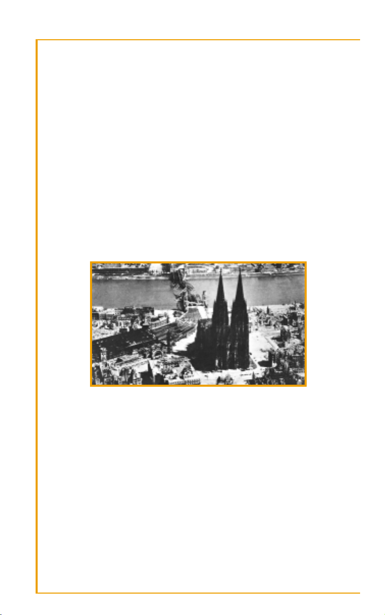
Urban devastation: the dream of Douhet and other prophets of air power.
While capturing the imagination, these initial air ventures had little effect
on the course of the war. Soon after the conflict ended, however, hints of
the future began to emerge. Stronger engines and better designs made new
strategies possible. The planes became bigger and faster, and were able to
carry heavier loads. The implications of these advances were set forth with
chilling vision by Italian Guilio Douhet, in his 1921 book Command of the
Air. He declared the era of ground war over; from now on war could be
fought and won in the air. Douhet proposed huge flying bombers that
could penetrate far behind lines of battle—bypassing the trench warfare
that had slowly eaten the morale of First World War armies—and pulverize enemy cities. The resulting panic and destruction would demoralize
one’s opponent and bring any war to a speedy conclusion.
3
Page 3
WORLD WAR II FIGHTERS
British and American designers read Douhet’s theories closely. Both began
designing large, long-range bombers with the intent, should war come, of
taking combat deep inside enemy lines. Both met strong internal
resistance to such a strategy: the thought of slaughtering huge numbers of
civilians was repugnant to the leadership, especially the American government of Roosevelt. It would be an ironic twist that those most reluctant
would be the ones most successful at wholesale urban destruction,
culminating in the atomic annihilation of Hiroshima and Nagasaki.
Equally ironic was that those who would goad the Allies into such devastation never put much stock in Douhet’s book. Germany’s rebuilt air power
concentrated on the bomber as battlefield support, and their planes were
accordingly smaller and with much shorter range. In the initial sweep of
war, this would be highly successful. When the time came for attempts at
behind-the-lines civilian assault, those most eager to decimate populations
would find their air power poorly equipped to help in the project.
AIR POWER AND THE SECOND WORLD WAR
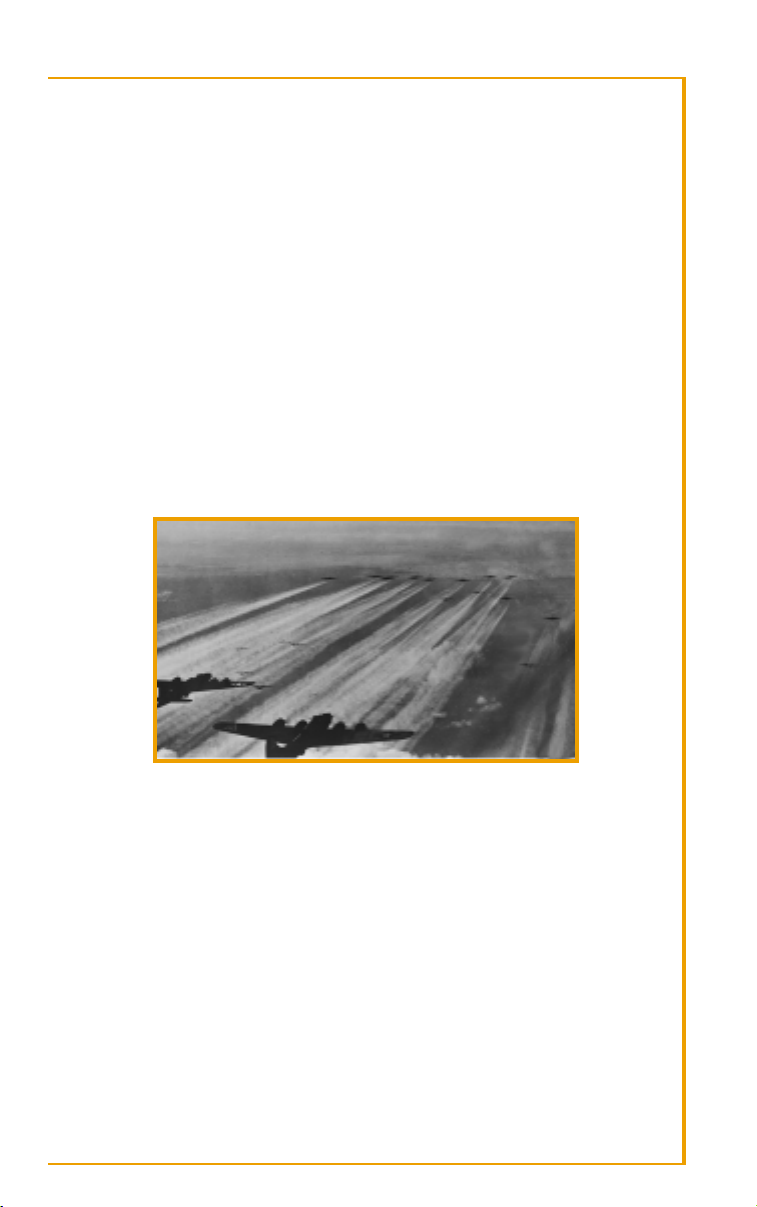
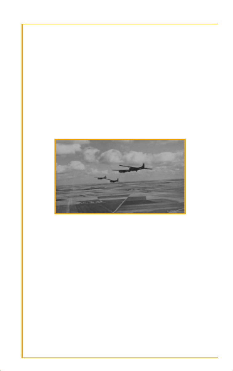
A vast Allied bomber armada heads for Hitler’s Reich.
As the Second World War progressed, the theories of Douhet and another
early champion of air combat potential, American William “Billy”
Mitchell, would be tested to their utmost. Some ideas proved accurate;
others had results far different than those envisioned. Douhet’s belief that
urban bombing would demoralize a nation proved quite incorrect when
Germany attempted to level British cities in the Battle of Britain. In fact, it
united the British people and hardened their resolve to see the war
through to its conclusion. Oddly enough, the British leadership failed to
learn its own lesson and followed the exhortations of another air power
devotee, Arthur “Bomber” Harris, perhaps the war’s most zealous advocate
of massive civilian bombing. He was convinced that the German people,
unlike his own island’s residents, would crumble and blame their leaders
for disaster if subjected to horrific raids. While the economic and strategic
results of the massive Allied bombing effort can be argued, the German
civilians, like their British counterparts, simply dug in and endured.
4
Page 4

AIR WAR IN WESTERN EUROPE
If civil collapse was not achieved, Britain alone could not accomplish the
other goals of large-scale bombing. It took the entry of the United States
into the war for the two nations to combine efforts and strategies and
impact the German military machine in a decisive manner. Britain favored
night time raids; America confidently chose daylight. Together this roundthe-clock bombing strategy aimed to pummel German industry into the
ground, and force the Luftwaffe into a defensive position, thus depriving
German forces on the front lines of air support.
A burden to bombing strategy was the distance which the planes had to
travel. Though equipped with some gun turrets, the bombers were easy
targets for fast-moving fighter planes which rose to meet the attack. For
raids along the nearby fringes of enemy territory, friendly fighters could fly
as escort to the larger planes and fly out to engage enemy fighters. As Allied
raids aimed deeper and deeper into German territory, however, the fuel
capacity of their fighters forced the tiny planes to turn back often well
before the bombers were over their prime targets. Left on their own, the
bomber losses were staggering. Champions of heavy bombing such as Harris and American General Carl Spaatz found themselves hard-pressed to
justify the losses against the questionable levels of damage inflicted to German military potential.
One result of the Allied bombing offensive that was an unqualified success
was its effect on the Luftwaffe. At a time when the tides of battle were turning against Germany, an air force designed for offense and ground support
in the field of battle was instead forced to stay on home turf and defend
industry and urban sites against an ever-growing enemy swarm. The
attrition rate for Allied flyers was horrifying, but the sheer manpower
available to the Allies meant losses could be replaced. Germany’s losses
were crippling. Skilled pilots were replaced by men who, due to time
constraints and scarcity of fuel, had little training. No matter what
“miracle weapons” Hitler’s weaponers might design, the skills of those
flying them ensured the impact of those wonders would be minimal.
AIR WAR: 1943–44
All across the western front in 1943, air power was playing a critical role.
The early mistake Hermann Goering, architect of German air power, made
in emphasizing smaller bombers for troop support was now apparent as
the four-engine long range bombers of the Allies roared over Germany. At
the war’s start, it was the Luftwaffe inspiring terror while screaming over
foreign skies. Now, over its own territory, Goering’s air force fought a desperate battle with an enemy growing in strength and confidence.
5
Page 5
WORLD WAR II FIGHTERS
In late 1942, the Allies escalated saturation bombing to round-the-clock
bombing. The British would fly over German cities by night and do their
best to utterly destroy them. By day, American bombers would attempt to
pinpoint more strategic targets and cripple German industry. American
faith in its bombing sights was misplaced, however: the height their planes
had to fly to avoid anti-aircraft artillery often negated any accuracy those
sights might provide. Bombs often fell miles from their target.
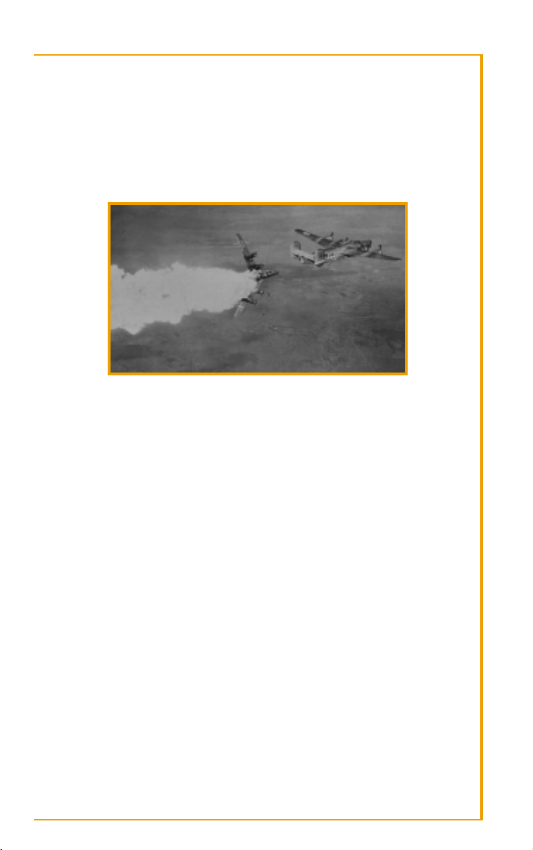
An American Liberator succumbs to German air defenses.
In summer 1943 the Allies bombed Hamburg for four consecutive nights,
taking 40,000 lives and creating a huge firestorm. The citizens—those who
survived—were stunned and numbed, but did not turn on their leaders. In
August, American planes from Libyan bases reached Ploesti, Romania’s
huge oil facility. As they flew over the Balkans, wave after wave of Luftwaffe fighters rose and hammered them. A quarter of the men on the mission died. Slightly more than one-sixth of the planes survived or were able
to be flown again. The facilities were soon repaired and operational.
For both sides, losses were terrible. The Luftwaffe were losing pilots at a
speed too great to replace. By late 1943, most planes rising to meet the
huge fleets of Allied bombers with their swarms of fighter support were
piloted by men with much less training, let alone battle experience. As for
the Allies, their fighter planes could not make the longer journeys to support the bombers. As better fighters were built and their range increased,
more German targets could be reached, but at a certain point, they had to
turn back—and then the Luftwaffe and its speedy planes could tear the
bombers to pieces. It would not be until 1944 that additional gas tanks
called ‘drop tanks’ would enable Allied fighters such as the P-51 Mustang
to penetrate deep into Nazi territory and destroy the Luftwaffe.
Equally dreaded was the 88 mm antiaircraft gun. Closely concentrated,
dug in near vital industrial areas and other targets sure to attract Allied air
raids, Flak guns may have taken out more bombers than the Luftwaffe
throughout the course of the war.
6
Page 6
AIR WAR IN WESTERN EUROPE
Amazingly, though fuel and pilots were scarce, fighter production continued
to rise in Germany. Hitler’s new minister of production, Albert Speer, had
reorganized the economy and cut as best he could through the multiple
layers of squabbling bureaucracies to actually increase all-around military
production. This in the face of round-the-clock bombing raises questions
as to the strategic, as opposed to propagandistic, value of the constant raids.
One definite result of round-the-clock bombing was that the Luftwaffe was
being slowly bled dry. While not destroying German industry, the bombing strategy had pinned Goering’s forces down on the home front. While
more planes were being built, they couldn’t keep pace with the losses
sustained against the Allies. Hitler began putting more and more hope—
and more and more resources—into a host of experimental weapons he
believed would turn the tide again to his favor. Goering, desperate to
regain favor, encouraged his Führer in those dreams. And in the East, the
loss of air support to defense over Germany left the Wehrmacht open to
the grinding, inexorable advance of the Red Army.
COUNTDOWN TO INVASION
By now the path of the war had become plain, like a hideous ballet whose
choreography had been planned and now must be followed through. German High Command knew that eventually the Western Allies were going
to strike across the English Channel and fortifications were accordingly
built. Generalfeldmarschall Erwin Rommel, considered one of Germany’s
best generals, was brought north from overseeing the occupation of what
was left of Mussolini’s regime to supervise the anticipated defense of the
beaches. He immediately began construction of an elaborate series of
defenses. If invasion came, he thought, and the Allies could be repelled on
the beaches, it would be years before they could muster another assault.
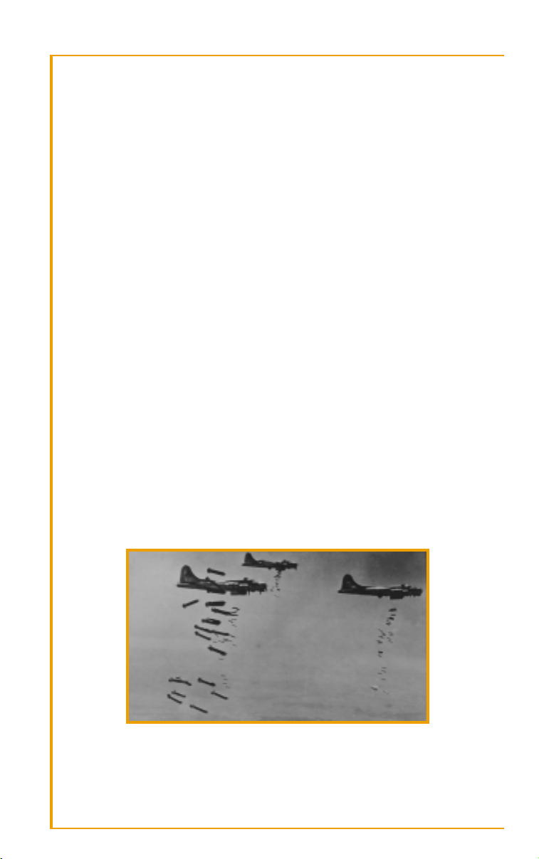
B-17s unload their “sticks” on the target.
7
Page 7

WORLD WAR II FIGHTERS
Hitler too hoped for a decisive blow on the beaches. In the face of the
crushing defeats being dealt the Wehrmacht in the East, he was still
convinced he could triumph over his enemies. He moved many of his best
divisions to France and the Low Countries to wait for the invaders and
smash them on the beaches. From there, holding them in the Italian
bottleneck would be easy. Full force could be concentrated on the Soviets,
who would then crumble. Hitler could then choose the time and place for
his victorious attack against the West.
Unfortunately for the Führer, his visions of destiny combined poorly with
faulty Nazi intelligence gathering. Allied diversions led German High
Command to grossly overestimate the size of the invasion force gathering
in England. Thus, more German divisions were held down in France, just
as the Red Army was hitting high gear in its most brutal offensives yet. Further Allied deception tricked Rommel into positioning most of the finest
armor and best troops far away from the actual landing point. As newlyappointed Supreme Allied Commander Dwight D. Eisenhower polished
plans for a Normandy landing, the best Germany could throw against an
attacker was waiting to the east, convinced the Allies would make a straight
line from Dover to Pas de Calais. Any landings to the west, thought Rommel, were diversionary attacks to be disregarded and dealt with later.
Meanwhile, Allied round-the-clock bombing continued its relentless pounding of the German landscape. The Luftwaffe was slowly being whittled away.
Though Albert Speer was achieving sinister miracles in keeping armaments
production high, damage to transportation infrastructure and the massive
consumption of fuel by units engaged to the south and east meant that
poorly trained pilots were rising to meet Allied flyers. The few skilled German pilots left were busy testing the secret weapons Hitler was always
boasting of, the weapons that in his wild inner world would turn the tide
of war. Allied bombs had hindered development of his V-2, the world’s first
rocket weapon, with which he hoped to bring the Blitz back to London.
With their debut put off by a year, the Führer instead demanded a renewed
conventional bombing assault on England at the start of 1944. The Luftwaffe
thus squandered precious planes on a futile “Baby Blitz”, as Londoners
called it. Until May 1944, a force of 500 bombers inflicted minimal damage
as Allied air defenses blasted more than half of them out of the sky.
In the East, the Red Army continued slowly steamrolling over the
Wehrmacht. Their 1943–44 winter offensive gave the Germans no rest. By
spring 1944, Germany was in full retreat in the East. The Soviets had their
choice of where to strike first. Reinforcements poured into the Red Army;
its Ural industrial base, untouched by Axis assault, sent a steady stream of
weaponry toward the front. The Germans in the East, on the other hand,
were increasingly desperate. Reinforcements and new weaponry were
being sent westward, to guard the beaches of France. Partisans roamed
behind the lines freely, pinning down Nazi troops, destroying supply lines
8
Page 8
AIR WAR IN WESTERN EUROPE
and communications. Years of slaughtering Soviet officers and starving
prisoners of war had made their enemy a merciless, furious foe. No German wanted to be taken prisoner by the Red Army. It was a virtual death
sentence.
In Italy, the first of the Axis nations to be invaded, the Allies saw a much
slower advance. Given terrain, climate, and the proximity to the Reich
itself, the German defense was more tenacious, despite the Italian populace’s
eager embrace of the Allied assault. The fighting was slow, torturous, and
bloody, with only more devastation likely as the Allies would slug their
way up the narrow peninsula. But as Italy and her liberators looked ahead,
the only thing that could shorten the bloodshed was on the horizon: the
attack from the west. The time had come at last for D-Day.
D-DAY
Gliders carrying troops into Normandy.
Operation Overlord, the largest amphibious assault ever undertaken,
began on June 5, 1944, during a break in an unexpected storm which nearly forced Supreme Allied Commander Dwight D. Eisenhower to call off the
invasion. Due to amazingly successful Allied deception as well as the
bureaucratic stupidities and inept intelligence-gathering of the Germans,
the landings were a surprise.
Massive air power had been called in. For weeks, bombing runs had been
softening up the coastal defenses, and surveillance flights had pinpointed
the major installations. Even Arthur “Bomber” Harris put aside his usual
obsession with terror bombing and committed his forces to aiding the
invasion, devastating the rail lines and infrastructure Germany needed if it
was to respond quickly to the assault. Allied fighters and bombers ruled the
skies: the Luftwaffe’s ill-advised “Baby Blitz” had left it even weaker than
it already was, and the landing sites were all within range of fighters based
in England.
9
Page 9
WORLD WAR II FIGHTERS
The Germans were taken in by almost every Allied diversion. Dummy
parachutists convinced Rommel that his instincts were correct: the forces
landing at Normandy were simply a diversionary attack. He refused to be
fooled; his main forces, including prized panzer divisions which might
have blown the landing troops to pieces, remained to the east, and would
stay there for crucial days to come. Surely the main landing would come
at one of the strategic harbors the Germans held, and had built impenetrable defenses around. What Rommel didn’t know was that the Allies had
built two floating harbors of their own, and that these huge devices were
on their way across the channel.
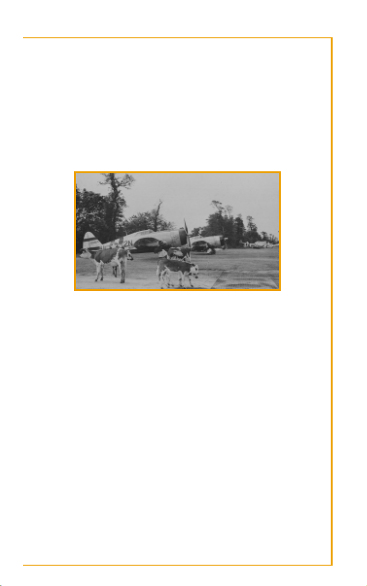
American Thunderbolts meet French livestock on a temporary runway.
The key to victory was landing as many forces as fast as possible, and the
Allies succeeded brilliantly. Before the Germans realized the main invasion
really was happening and could get reinforcements to contain the beachheads, the floating harbors had unloaded artillery, armor, and thousands
of men. Even a terrific storm’s destruction of one of the artificial harbors
on June 19 couldn’t help the Germans. The first day’s hesitations cost
them the battle. Their numerical superiority in troops and armor was too
slowly deployed, and their air defenses had been shattered by wave after
wave of Allied planes.
Still, the destruction was terrible. The defenders gave ground grudgingly,
fighting field by field, inflicting heavy losses on Americans in the west and
the British further east. But after bitter initial fighting, by the 14th the
Americans, under the colorful General George Patton, had broken through
German lines and drove toward Cherbourg, which fell on the 26th. The
Allies now had a true harbor through which they could pour weaponry
and supplies. The Nazis had done their best to destroy the city and its harbor, but within three weeks Cherbourg was beginning to unload further
invasion forces.
10
Page 10

AIR WAR IN WESTERN EUROPE
The Allies had firmly established themselves on the continent, though
progress was slower than initially anticipated. Field Marshal Bernard
Montgomery, the hero of El Alamein, the crucial battle which turned the
tide against Germany in North Africa, was unwilling to take the heavy losses a major British push would entail. The Americans to the west found
themselves in terrain which hindered the advance of their heavy armor.
Once they attached gigantic spikes to the front of their tanks, however,
they could go off road again, punching through the hedgerows of northern France and into the face of the ferociously-resisting Germans.
As American armor hammered in the west, to their east, Nazi armor was
doing its best to push the British back to the beaches. But from the air
came swarms of Allied fighters and bombers, pinning the tanks in their
positions, making movement slow and deadly. Round-the-clock air attacks
from Allied planes and futile offensives had left the Luftwaffe, in the hour
it was most needed, outnumbered and outgunned.
From Berlin, Hitler made a confusing situation worse, issuing contradictory orders, berating, ignoring, and overruling his generals. He refused calls
for a counterattack against the menacing American armor which threatened to buckle the entire defensive line in France. He didn’t want to risk
the army; instead it began to be whittled and chipped away as it was slowly pushed back, with no reserves to replace the losses.
Meanwhile, his fervent belief in his secret weapons program finally bore
fruit in mid-June. The first V-1’s, pilotless jet planes loaded with explosives,
began falling on London. Although the appearance of these odd bombs
were a blow to British morale—Churchill even demanded retaliatory poison gas attacks, but was overruled by the Americans—actual damage was
nowhere near as great as Hitler envisioned. The V-1’s were easily shot
down, and many others missed their London target. Panic did not set in;
London was not evacuated; the Allied war effort continued unhindered.
Once again Douhet’s predictions failed to come true. The weapons
designed to suddenly win the war only hurried the Allies to break out of
the Normandy beach heads to reach the V-1 launch sites.
Nazi generals finally got the hint that Normandy was, indeed, the big landing by late July and began moving their long-sidelined armor from Pas de
Calais to intercept American tanks. By then the difficult terrain was behind
Patton’s forces, however, and open country well-suited for armor was now
before the audacious general. Hitler finally agreed to a counterattack at
Mortain, and issued orders to strike—orders which were intercepted and
decoded by the Allies, who had broken almost all the German codes and
knew exactly when and where the attack was to come. Allied air power,
combined effectively with the ground troops, stopped the assault in its
tracks. As the Americans pummeled their attackers, the British and Canadians previously pinned down by those German troops moved south. Had
Montgomery not once again been too cautious and held back his best
11
Page 11

WORLD WAR II FIGHTERS
troops, the Germans would have been trapped and annihilated in another
Stalingrad. As it was, many of them escaped, although with huge losses in
life and equipment. By late August, the British were clearing Belgium and
capturing the V-1 launch sites, and to the south, defying Hitler’s orders to
level the city, Gen. von Choltitz pulled out of Paris. On August 25, advancing American troops held back and let Charles de Gaulle’s Free French
forces liberate their long-suffering capital. Ten days earlier, more Allied
troops had struck from the south, landing on the French Mediterranean
coast. Churchill had heatedly opposed this operation, pushing instead for
continued pressure in Italy. Given the choice of advancing slowly to an
Alps range filled with Nazis armed to the teeth or seizing the ports of Marseilles and Toulon, Eisenhower understandably overruled the British prime
minister’s strategy.
The German lines were crumbling. From the Low Countries to the Swiss
frontier, Allied troops were racing toward the borders of the Reich. Hitler
grudgingly allowed the troops in the south of France to pull back and
avoid encirclement. Almost all of France had been taken in two months’
fighting. With the Nazi armies went the wartime French government based
in Vichy. Coming to power through French defeat, they now faced disaster of their own as France was freed, having tied themselves to the fate of
their conquerors. From southwest Germany, they watched as the Wehrmacht abandoned France and regrouped along the border, holding as many
Low Country ports as it could.
That holding of ports became ever more troublesome for the Allies as 1944
progressed. While Cherbourg was slowly being cleared, other liberated
ports such as Brest had been so badly wrecked by the retreating Germans
that they were unusable. As Germany’s supply lines shortened, lessening
the strain on its battered infrastructure, the Allied lines stretched forward,
with huge levels of troops, planes, tanks, and artillery to maintain. The
damage they had done to infrastructure to cripple Nazi supply lines now
haunted them. The only thing that helped them get as far as they did
before supply became a major issue was the valiant drivers of a massive
convoy of trucks laden with fuel and weapons which came to be called the
Red Ball Express. A round-the-clock substitute for the ruined rails ran nearly 90,000 tons of supplies from the landing beaches of Normandy deep
into France in the space of a few weeks.
By the time the Allies were closing in on the Reich, even that fuel was running low. Patton and Montgomery bickered over who should get the last
fuel reserves and push ahead. Eisenhower sided with the difficult British
general, who planned to force his way across the Rhine into Holland,
allowing the Allies to exploit the great harbor of Antwerp, which the
British had seized virtually intact. Montgomery swung from his usual toocautious approach to overconfidence. Ignoring warnings of strong German
armor nearby, he ordered a parachute brigade dropped behind enemy
12
Page 12
AIR WAR IN WESTERN EUROPE
lines—and on the other side of town from the Arnhem bridge the paratroopers were to seize. The Germans cut them off, drove them away from
the bridge, and shot them to pieces. Only a fifth of them survived to
become prisoners or escape back across the Rhine.
Surprised by the stiffening German resistance, stunned by Montgomery’s
defeat, and above all, desperately low on fuel, the Allied advance slowed as
autumn progressed. Eisenhower had hoped for an end to war in Europe by
autumn; an obstinate Reich had held out. The Allies would have to wait
until spring—winter was coming, and conditions would be too poor for
any major offensive on the Western front. Eisenhower’s only solace was
that, given the weather and the continuous beating Germany was taking
in the East, at least Hitler couldn’t launch any counterattacks either.
THE ARDENNES OFFENSIVE
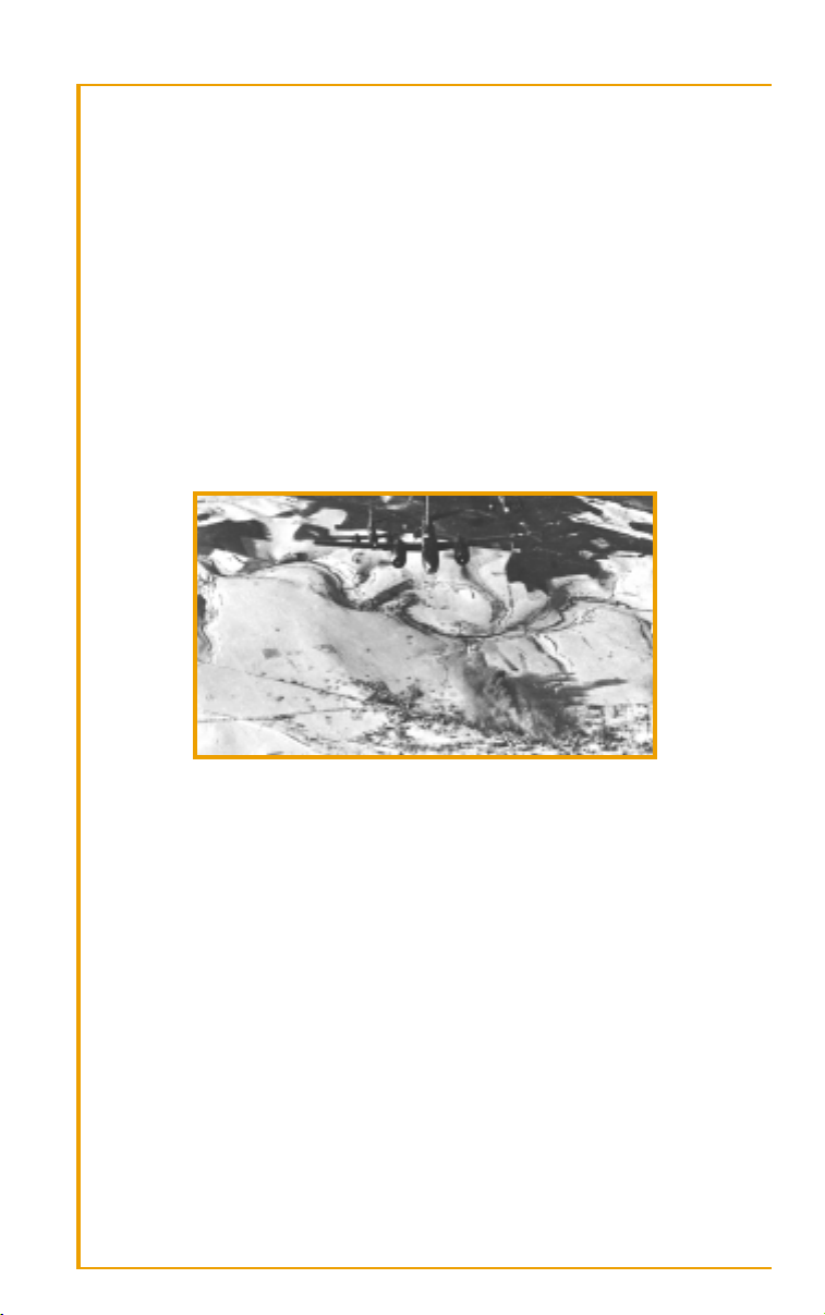
Allied medium bombers over “The Bulge.”
Hitler counterattacked on December 16, 1944, stunning the Allies by sending forth troops and armor under cover of fog and cold. Now, with the
Eastern front in collapse and his final attempts at terror bombing London
out of the war proven futile, he decided on a final, furious offensive that
might change the course of the war.
While on the Eastern front the amount of territory between Germany and
the Soviets was ample, in the West the front was uncomfortably close to
the Reich’s industrial base. While there might be time to stall and regroup
against the Soviets, there was little time to waste before the Allies would be
in the vital Ruhr region. Thus, as entire armies were being annihilated on
the Polish frontier, Hitler massed more than twenty divisions of new
troops and equipment in the West, augmenting it with the last reserves of
manpower he could find within the Reich. Total mobilization had finally
been declared by Speer. Now 16-year-old boys sat in the cockpits of the
Luftwaffe’s fighters and filled the ranks of German rifle companies.
13
Page 13
WORLD WAR II FIGHTERS
Hitler planned to deliver a stunning, crushing blow, pushing the Allies
across the Channel in a second Dunkirk. This new Blitzkrieg would
undoubtedly be so successful that it would end in time to switch the forces
back to the East before the Soviet winter offensive would begin. Hitler’s
estimation of the Allies, especially the Americans who now made up the
bulk of the force in the West, was that they were a weak-willed assembly,
ready to crack with the first serious defeat. For the third time in less than
fifty years, Germany planned a sudden attack through the Low Countries.
Allied intelligence summed up the Wehrmacht as a spent force, unable to
muster anything beyond a tenacious but doomed defense. Over the skies
of Germany, Allied bombers flew virtually unopposed, pulverizing cities
with impunity. The vast resources of Ukraine and Romania were in Soviet
hands; only the oil fields of Hungary remained for Hitler to draw upon.
The Allied lines were drawn thin across the Ardennes forest, but could
hold firm until supplies arrived and a spring offensive could begin.
It was with this mutual underestimation that the last Nazi offensive began.
In cold and snow, through the heavy woods of Luxembourg and Belgium,
a 400,000 man German force slammed into a front guarded by 80,000
Americans who were outnumbered in tanks and (by a more than four-toone ratio) artillery. In the long-gone days of 1940, the attack would have
waited for a clear day, so that the mighty Luftwaffe could first bludgeon
the enemy from the air. In 1944, the Germans instead counted on poor
weather to keep the Allied air forces’ far superior strength on the ground.
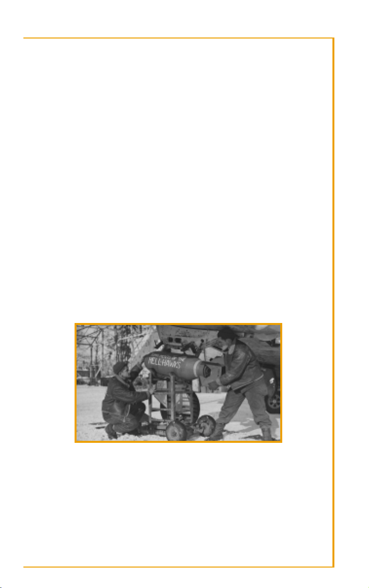
American ground crewmen prepare a holiday gift for the enemy.
The Americans were caught totally off-guard. Eisenhower scrambled to move
forces to the Ardennes as two divisions were destroyed and others were
pushed back toward the strategic town of Bastogne. A division of US paratroopers secured the town just in time; the Germans surrounded it but
failed to take it. This slowed the advance toward the Meuse River, giving
American armor time to regroup and stop the attack on the water’s east side.
14
Page 14

AIR WAR IN WESTERN EUROPE
To the south sat the American 3rd Army. Patton had been waiting for the
fuel to take his attack east into Germany. When the sudden offensive
began, Allied command was alarmed at the sparse defenses in the German
path, and the time it would take distant reinforcements to arrive. To everyone’s astonishment, Patton promised them he could disengage in the Saar,
change direction, and swing north to relieve Bastogne in 48 hours. To
everyone’s further astonishment, he did just that, not only getting his
forces to the front but hurling them into combat against the German
armor besieging the city. He smashed his way through in the face of brutal
panzer counterattacks, breaking the iron ring around Bastogne and freeing
the pinned 101st Airborne Division.
Despite the help Montgomery’s timidity gave them, the Germans’ bout of
good luck came to an end on Christmas Eve 1944, when the bad weather
which kept the Allied air forces grounded gave way. In the cold, clear skies
over the Ardennes, over 3,000 planes took to the air, and aimed for the
slowly stalling German advance. To the east, the Luftwaffe had orders to
attempt yet another air offensive against the enemy. Untrained pilots with
little ammunition and less fuel climbed into what was left of the Luftwaffe
with visions of chasing the Allied planes (by now outnumbering them
ten-to-one) from the sky.
So the Allies and Nazi Germany found themselves, on the Western Front,
in desperate battle. Hitler was flinging his last reserves in a final assault,
convinced he could sweep his enemies into the Atlantic and buy time to
win in the East. Both sides prepared to throw all they had into this showdown for control of the war’s direction, and perhaps its outcome. At the
end of 1944, the future of the planet was being decided on the ground and
in the skies above the dense forests of the Ardennes. The West had to get
reinforcements to the lines before they were overwhelmed, and hope for
the weather to clear so their superior air power could be deployed.
15
Page 15
WORLD WAR II FIGHTERS
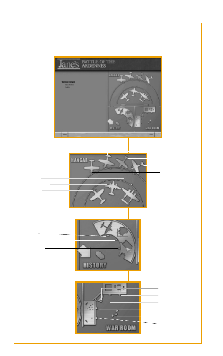
MUSEUM MAP
P-38J
ME 262A-1A
P-47D
P-51D
BF 109G-6
SPITFIRE F. IX
FW 190A-8
AIR FORCES
HISTORICAL OVERVIEW
GROUND FORCES
WELCOME DESK
16
MULTIPLAYER
QUICK MISSION
MISSION BUILDER
CAMPAIGN
ACES
SINGLE MISSION
Page 16
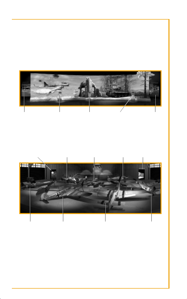
THE EXHIBITIONS
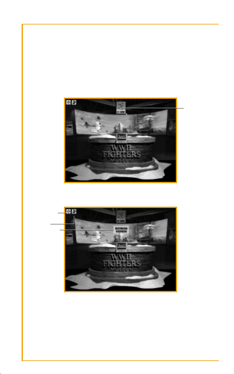
THE EXHIBITIONS
Upon entering the museum, you see the Welcome Kiosk. If you want to
jump right into flight, click the Fly Now! poster hanging in the top center
of the screen. You immediately begin a quick mission without configuring
your flight.
JUMP DIRECTLY
INTO A MISSION
NAVIGATING THE MUSEUM
QUICK NAVIGATION
BUTTON
BACK BUTTON
CLICK ON AN ACTIVE
LABEL TO MOVE
FORWARD
To go to the previous screen, left-click the BACK button in the top left
corner of the screen.
Use the QUICK NAVIGATION button to jump to another part of the
museum. Click to bring up a screen listing the various locations in the
museum. Select a location to be instantly transported there.
17
Page 17
WORLD WAR II FIGHTERS
PANNING YOUR VIEW
At some locations, you may need to pan your view in order to see everything before you. To pan your view, move the mouse cursor to the left or
right side of the screen.
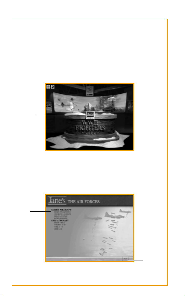
VIEWING KIOSKS
Each museum room has a number of kiosks. When you move the mouse over
a kiosk, it lights up. Click on a kiosk to view the content at that station.
CLICK ON KIOSK
TO VIEW CONTENT
The content you see on a kiosk monitor varies. Some kiosks display information on vehicles or historical subjects. Others select a mission.
INFORMATION KIOSKS
All Information Kiosks have a contents page. Here you choose the subject
about which you want to learn.
CONTENTS
BACK
18
Page 18
THE EXHIBITIONS
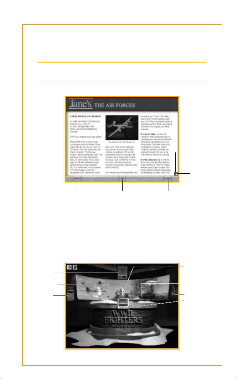
When you move your mouse over the contents page, the option under the
mouse turns white. Click to view detailed information on the subject.
Select the BACK button to exit the kiosk screen.
Video Button: Many kiosks have an additional Video button. Use
this to watch video reference material on the current subject.
Viewing Information
GO TO THE
PREVIOUS
PAGE OF
INFORMATION
GO TO THE
NEXT PAGE OF
INFORMATION
DISPLAY THE PREVIOUS
SUBJECT IN THE CONTENTS
DISPLAY THE NEXT
SUBJECT IN THE CONTENTS
RETURN TO THE
CONTENTS PAGE
Mission Kiosks
The Mission Kiosks are found only in the War Room. The controls in the
mission kiosks vary depending on the type of mission. See the Gameplay
Guide included in your Jane’s
®
WW II Fighters box for information on
selecting missions and building your own missions.
WELCOME DESK
JUMP DIRECTLY
INTO A MISSION
GO TO AIR FORCES
KIOSK
GO TO HANGAR
GO TO HISTORICAL
BACKGROUND
KIOSK
GO TO GROUND
FORCES KIOSK
GO TO WAR ROOM
SET GAME OPTIONS,
VIEW CREDITS, OR
WATCH THE GAME
INTRO ANIMATION
19
Page 19
WORLD WAR II FIGHTERS
INFO ROOM
In the Info Room, you can learn about bombers and other aircraft that
operated over Europe, as well as the types of ground vehicles and weapons
that operated on the Western Front in late 1944. Also, the Historical Background Kiosk provides you with information on the Ardennes Offensive,
known in the US as the Battle of the Bulge.
GO TO HANGAR VIEW INFORMATION
ON ALLIED AND
AXIS BOMBERS
AND TRANSPORTS
VIEW HISTORICAL
BACKGROUND ON
THE ARDENNES
OFFENSIVE
VIEW INFORMATION
ON ALLIED AND AXIS
GROUND VEHICLES
GO TO WAR ROOM
HANGAR
In the Hangar, you can learn about the museum’s featured aircraft.
GO TO P-38JGO TO INFO ROOM GO TO ME 262A–1A GO TO P-47D GO TO INFO ROOM
GO TO SPITFIRE F. IX GO TO BF 109G-6 GO TO P51D GO TO FW 190A-8
VIEWING THE AIRCRAFT
When viewing an airplane, you can go take a closer look at the cockpit,
armament, and powerplant. The curator provides commentary on each
aspect of the airplane.
20
Page 20

GO TO THE COCKPIT
THE EXHIBITIONS
GO TO THE
ARMAMENT
VIEW INFORMATION
ABOUT THE AIRPLANE
GO TO THE ENGINE
COMPARTMENT
Special Test Flight Buttons: Each of the Airplane Kiosks in the
Hangar has a Test Flight button. Click this to fly the airplane of your
choice in a non-hostile environment. Here you can test your flying
and gunnery skills.
WAR ROOM
In the War Room, you can select a single mission, build a custom mission
of your own, start or continue a campaign, or join a muliplayer game. In
addition, a special Aces Kiosk has video interviews with the aces who flew
the actual planes.
GO TO SINGLE MISSIONS KIOSK
GO TO CAMPAIGNS
KIOSK
GO TO MULTIPLAYER
KIOSK
GO TO MISSION
BUILDER KIOSK
GO TO QUICK MISSION KIOSK
SELECTING MISSIONS
The controls in the mission kiosks vary depending on the type of mission.
See the Gameplay Guide included in your Jane’s WW II Fighters box for
information on selecting missions and building your own missions.
21
Page 21

WORLD WAR II FIGHTERS
JANE’S®WW II FIGHTERS
Museum Collection
In the 1930s, the antiquated, wooden biplanes of WW I were replaced by
a new generation of sleek, metallic monoplanes that would redefine combat. Improvements in the engines, airframes, and firepower of these new
aircraft fostered the great race of the decade—which country could create
the fastest, most destructive flying machine in the world.
FOCKE-WULF FW 190A-8
Germany prepared for war with the expectation that mobile warfare and
combined arms would make any future conflict a brief if violent affair. It
was widely believed that a successor to the Luftwaffe’s frontline fighter, the
Messerschmitt Bf 109, would hardly be necessary in the age of Blitzkrieg
warfare. Thus it was with unusual foresight that the Reichsluftfahrtminis-
terium (RLM), or Air Transport Ministry, chose to fund the development of
an air superiority fighter in 1938, just as the Luftwaffe was standardizing
on Messerschmitt’s outstanding fighter. Who would have guessed then
that a particularly compact airplane—designed by Kurt Tank and his team
at Focke-Wulf—would become one of the most successful propeller-driven
fighters ever produced in great numbers?
Certainly the officials at the RLM did not expect much from Tank’s machine.
True, the airplane was small and sleek, with an attractively thin fuselage,
extremely low-drag profile, and excellent structure. But the fact that it was
built around a bulky radial engine instead of a narrow inline engine did
not bode well for its future. Three prototypes powered by 18-cylinder BMW
139 radial engines were ordered and built, the first flight occurring in early
June 1939. The engines were found to be wanting and were replaced by the
heavier but more powerful 1,192 kW (1,600 hp) BMW 801C. The added
weight forced some changes in the airframe, including moving the cockpit
further aft in order to shift the center of gravity; combined with a now
larger engine cowling, the pilot’s view was diminished slightly. The wing
was also lengthened, though this was more beneficial than detrimental.
Trials with pre-production aircraft revealed teething trouble with the airplane’s ten-blade cooling fan, but the overall impression of the fighter was
that it was a delight to fly. Orders were delivered for a hundred Fw 190A-1
aircraft armed with four 7.7 mm MG 17 machine guns—two in the cowling
and another pair in the wing roots—all firing through the propeller. To
increase firepower, 20 mm MG FF cannons were added to points outboard
of the landing gear. By the time the A-2 arrived, the wing root guns were
being replaced by the new 20 mm MG 151/20, necessitating the bulged
plates on the upper wing surfaces.
22
Page 22

MUSEUM COLLECTION
It was the Fw 190A-3 powered by the 1,268 kW (1,700 hp) BMW 801D-2
that became a menace to the RAF in the summer of 1942. Flying against
Spitfire Vs, the Fw 190s proved themselves in every category of performance save turning ability. Able to initiate or break off combat at will, the
Fw 190s dominated the skies over northwest Europe. The power of the new
fighter was such that the English would have to scramble to wrest air
superiority from a smaller Luftwaffe force facing them across the channel.
A number of Fw 190A sub-variants followed to fulfill an ever-widening
number of roles. Originally intended to be an air superiority fighter, the
Würger (“butcher bird”) quickly became a jack-of-all-trades, armed with
cameras for reconnaissance; external fuel tanks for long-range missions;
bombs for use as a fighter-bomber; tropical equipment for desert-fighting;
wing pods for use as a bomber-destroyer; additional armor for bomberramming; radar equipment for use as a night-fighter; bomb racks for
carrying torpedoes; and various combinations of the above.
As the war progressed, the Fw 190 assumed roles earlier held by such
esteemed German aircraft as the Ju 87 Stuka and other close support
aircraft. Beginning in late 1942, the heavily-armored Fw 190F—which also
featured an incredible number of sub-variants—was developed for use in
the ground attack role. This was followed by the 190G series, a close
support version with additional fuel for increased combat range.
As the radial engine Fw 190 was being perfected, Focke-Wulf simultaneously developed versions of the fighter (190B and C series) with inverted-V
liquid-cooled inline engines. The radial engine 190s performed poorly at
high-altitude, and as defense of the Reich took on importance, the need
for a heavily-armed high-altitude fighter became greater. The result was the
famous 190D or “Dora” series of fighters, which began to see service only
in late 1944. Powered by a 1,323 kW (1,776 hp) Junkers Jumo 213A-1
engine, the Fw 190D was considered on a competitive footing with the P51 or Spitfire IX.
In total, just over 20,000 Fw 190s of all types would be produced by war’s end.
FW 190A-8 DATA
Engines One 1,268 kw (1,700 hp) BMW 801D-2
Wing Span 10.5 m (34 ft 5.5 in)
Length 8.96 m (29 ft 4.75 in)
Max T-O Weight 4,900 kg (10,802 lb)
Max Level Speed 657 km/h (408 mph)
Range 800 km (497 mi)
Armament Two 12.7 mm machine guns, two 20 mm cannon,
and either two-four 20 mm or two 30 mm cannon
23
Page 23

WORLD WAR II FIGHTERS
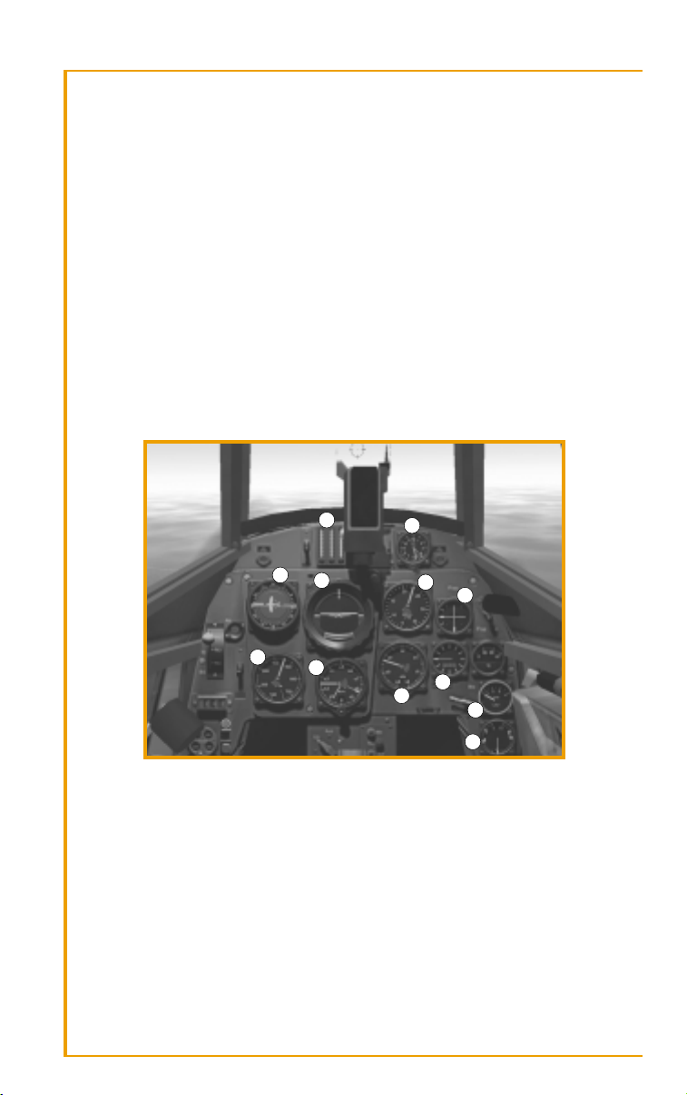
FW 190A-8 COCKPIT
1 2
3
4 5 6 7
8
1. AMMUNITION COUNTER
2. RADIO DIRECTION FINDER
3. AIRSPEED INDICATOR
4. ARTIFICIAL HORIZON
5. RATE OF CLIMB INDICATOR
6. COMPASS
7. BOOST
10
14
11 12
8. ALTIMETER
9. TACHOMETER
10. FUEL AND LUBRICANT PRESSURE GAUGE
11. FUEL GAUGE
12. CLOCK
13. OXYGEN PRESSURE INDICATOR
14. ENGINE TEMPERATURE
9
13
FW 190A-8 GAME LOADOUTS
Clean Fuel Gun Pods Gun Pods 500 kg 250 kg
Primary Guns Type/Number 20 mm x 4 20 mm x 4 20 mm x 2 20 mm x 2 20 mm x 4 20 mm x 4
Location Wing/ Wing/ Wingroot Wingroot Wing/ Wing/
Wingroot Wingroot Wingroof Wingroof
Rounds/Gun 200 200 200 200 200 200
Secondary Guns Type/Number 13 mm x 2 13 mm x 2 13 mm x 2 13 mm x 2 13 mm x 2 13 mm x 2
Location Cowling Cowling Cowling Cowling Cowling Cowling
Rounds/Gun 475 475 475 475 475 475
Secondary Guns Type/Number – – 30 mm x 2 30 mm x 2 – –
Location – – Wing Pods Wing Pods – –
Rounds/Gun – – 55 55 – –
Bomb Load Type ––––500 kg250 kg
Location ––––Centerline Centerline
Number ––––1 1
Drop Tank Type – 300 ltr – 300 ltr – –
Location – Centerline – Centerline – –
Number – 1 – 1 – –
Fuel,
24
Page 24

MUSEUM COLLECTION
LOCKHEED P-38 LIGHTNING
Developed before the war for use as a long-range, high-altitude fighter, the
P-38 took on a wide variety of additional combat roles, including escort,
fighter-bomber, photo-reconnaissance, torpedo-bomber, light transport,
and even an airborne ambulance. The adaptable Lightning served until the
end of the war—the only fighter to precede the war and remain in production until Japan surrendered. With its unusual twin-engine twin-boom
design, it was certainly the most recognizable airplane in the entire Allied
inventory—the Germans called it der Gabelschwanz Teufel or “the ForkTailed Devil”, while the Japanese term translated as “one pilot, two fighters.”
The P-38 was a credit to Lockheed, who in the early ’30s had never developed a purely military airplane. It was designed to meet a 1936 US Army
Air Corps specification for a pursuit fighter capable of 360 mph (576 km/h)
at 20,000 ft (6,100 m). A proposal was accepted the following year, and the
prototype XP-38 flew for the first time on 27 January 1939. In many respects
it was a truly revolutionary airplane. At the time of its introduction, it was
the fastest fighter in the world, and it also had the longest range. It had an
all-metal flush-riveted skin and turbo-supercharger for solid high-altitude
performance. And it was the first fighter to employ a tricycle landing gear.
The USAAC was pleased enough to issue a Limited Procurement order for
13 YP-38 fighters. These were fitted with two 1,150 hp (858 kW) Allison
V-1710-27/29 engines and carried a powerful array of guns in the nose: one
37 mm cannon, two .30 caliber machine guns, and two .50 caliber
machine guns.
An additional thirty production fighters designated P-38 were delivered in
July 1941. The .30 caliber guns were replaced by additional .50 caliber
guns, and pilot armor was added. These aircraft were turned over to training duties when the first combat-ready version, the P-38D, arrived in
August 1941. This version featured self-sealing fuel tanks as well as a redistribution of the elevator balance weights, which improved dive recovery
and eliminated problems associated with tail-buffeting.
The P-38E introduced what would become the fighter’s standard gun armament: four .50 caliber machine guns in the nose forming an arc over one
20 mm cannon. This was followed by the P-38F, which was fitted with two
1,325 hp (988 kW) V-1710-49/53 engines and underwing racks for up to two
1,000 lb bombs or long-range drop tanks. The latter increased the airplane’s
combat range to an astonishing 1,750 miles (2,816 km).
The P-38G and H each saw increases in engine performance. The P-38J,
which entered service in August 1943, was powered by two 1,425 hp
(1,063 kW) V-1710-89/91 engines and introduced powered ailerons and a
better cooling system. This was followed by the P-38L, the most numerous
version built and the first to carry underwing rockets. Some P-38Js and Ls
25
Page 25

WORLD WAR II FIGHTERS
were later adapted as pathfinders, complete with a bombardier and Norden
bombsight in a transparent nose. The P-38M, which arrived too late to
serve in the European theater, was a two-seat night-fighter carrying a radar
in a chin pod.
P-38J DATA
Engines Two 1,425 hp (1,062 kW) Allison V-1710-89/91
Wing Span 52 ft 0 in (15.85 m)
Length 37 ft 10 in (11.53 m)
Max T-O Weight 21,600 lb (9,798 kg)
Max Level Speed 414 mph (666 km/h)
Range 450 mi (724 km)
Armament One 20 mm cannon and four .50 caliber machine
guns, plus up to 2,000 lb of external stores
P-38J COCKPIT
3
2
1
5 6
7
10
1. COMPASS
2. SUCTION GAUGE
3. CLOCK
4. DIRECTIONAL GYRO
5. ARTIFICIAL HORIZON
6. MANIFOLD PRESSURE GAUGE
7. TACHOMETER
26
4
11 12 13
16
17
8. ENGINE GAUGE CLUSTER:
FUEL & OIL PRESSURE,
TEMPERATURE (LEFT ENGINE)
9. ENGINE GAUGE CLUSTER:
FUEL & OIL PRESSURE,
TEMPERATURE (RIGHT ENGINE)
10. FRONT (RESERVE) FUEL TANKS
GAUGE
11. ALTIMETER
8 9
14
15
12. AIRSPEED INDICATOR
13. BANK AND TURN INDICATOR
14. RATE OF CLIMB INDICATOR
15. CARBURETOR AIR TEMPERATURE
GAUGE
16. REAR (MAIN) FUEL TANKS GAUGE
17. HYDRAULIC PRESSURE GAUGE
Page 26

MUSEUM COLLECTION
P-38J GAME LOADOUTS
Clean Fuel HVAR HVAR 500 lb 500 lb 1000 lb
Primary Guns Type/Number .50 cal x 4 .50 cal x 4 .50 cal x 4 .50 cal x 4 .50 cal x 4 .50 cal x 4 .50 cal x 4
Location Fuselage Fuselage Fuselage Fuselage Fuselage Fuselage Fuselage
Rounds/Gun 500 500 500 500 500 500 500
Secondary Guns Type/Number 20 mm x 1 20 mm x 1 20 mm x 1 20 mm x 1 20 mm x 1 20 mm x 1 20 mm x 1
Location Fuselage Fuselage Fuselage Fuselage Fuselage Fuselage Fuselage
Rounds/Gun 150 150 150 150 150 150 150
Bombs Type – – – – 500 lb 500 lb 1,000 lb
Location – – – – Wing Wing Wing
Number – – – – 2 2 2
Rockets Type – – HVAR HVAR – HVAR –
Location – – Wing Racks Wing Racks – Wing Racks –
Number/Rack – – 5 5 – 5 –
Drop Tanks Type – 165 US gal – 165 US gal – – –
Location – Wing – Wing – – –
Number – 2 – 2 – – –
Fuel, HVAR
MESSERSCHMITT BF 109
Perhaps the most famous German fighter ever built, the Bf 109 earned a
place in the annals of all-time great warplanes by virtue of its early-war
performance alone—to say nothing of the fact that it faithfully served as
the mainstay of the Luftwaffe from before hostilities commenced in 1939
until the capitulation of Germany in May 1945. A fundamentally good
design allowed it to be employed in an incredibly wide variety of tasks, and
the fact that some 35,000 were built speaks volumes of the airplane’s
usefulness.
In 1933 the Reichsluftfahrtministerium (Air Transport Ministry), or RLM,
issued a specification for a monoplane fighter to replace the biplane fighters (Arado Ar 68 and Heinkel He 51) then available to the still-clandestine
Luftwaffe. Contracts for prototypes were awarded to Arado, Bayerische
Flugzeugwerke, Focke-Wulf, and Heinkel. Few expected Willy Messerschmitt and Bayerische Flugzeugwerke to produce a winning design in the
area of high speed fighters, whatever the success of their earlier Bf 108 Taifun touring airplane. When it came time for competitive trials, however,
Messerschmitt’s Bf 109 V1 performed admirably against the Ar 80 V1, Fw
159 V1, and He 112 V1. A low wing monoplane with retractable landing
gear, the 109 was clearly a breed apart from the open cockpit designs proposed by Arado and Focke-Wulf, or Heinkel’s high-wing fighter. The RLM
ordered an additional 10 experimental Bf 109s, but—hedging their bets
perhaps—ordered 10 of the Heinkel design as well. This led to further trials in late 1935, during which the Bf 109 proved its superiority.
27
Page 27

WORLD WAR II FIGHTERS
Ironically, the 109 first flew under the power of imported Rolls-Royce
Kestrel VI engine, since the Jumo 210 engine intended for it was not
finished.
The proposed Bf 109A was cancelled when its armament of just two 7.9
mm MG 17 machine guns in the upper cowling was deemed inadequate.
Provision was made for a possible third gun firing through the airscrew,
and a number of Bf 109B-1, B-2, and C fighters were delivered to Luftwaffe
units operating with the Condor Legion in Spain. Pilots gained considerable experience while participating in the Spanish Civil War, formulating
tactics and suggesting improvements to the 109, which already was
proving capable of going head-to-head with the best Republican fighter,
the Russian-built Polikarpov I-16.
The Bf 109D powered by the Daimler-Benz DB 600 engine was produced
in limited quantities, but by the time the war broke out in 1939, the Bf 109E
with the more powerful 820 kW (1,100 hp) DB 601A engine was taking the
place of the ‘Dora’ on the production lines. The 109E or ‘Emil’ housed
additional MG 17 machine guns or 20 mm MG FF cannon in the wings,
and some variants housed a fifth MG FF cannon in the propeller hub. The
Emil was produced in great numbers—it was the primary fighter used in
the Battle of France and the Battle of Britain—and many were exported to
foreign clients in return for hard cash. The airplane’s tremendous speed
advantage was its greatest asset in the first few years of the war. It suffered
against early RAF Spitfires in the area of turning performance, and its fuel
capacity was small (a serious liability, as the Germans discovered, during
the Battle of Britain), but otherwise the Bf 109E was the superior machine.
The ‘Emil’ began to take on additional roles: fighter-bomber, reconnaissance airplane, high-altitude interceptor with power-boosting, and a
modified version for fighting in the Mediterranean.
By the time Germany invaded the Soviet Union in 1941, the Bf 109F was
being introduced. This airplane—now powered by an 894.2 kW (1,200 hp)
DB 601N or 969 kW (1,300 hp) DB 601E engine—eliminated the aerodynamically unattractive braces under the tailplane while introducing a
retractable tailwheel. The wing guns were eliminated entirely—pilots
would now rely on a pair of MG 17s in the upper nose deck, and a single
high-velocity MG 151/20 cannon firing through the airscrew.
In the summer of 1942, the Luftwaffe introduced the Bf 109G into service.
This model was powered by the 1,100 kW (1,475 hp) DB 605 series of
engines, the intention being to increase the airplane’s speed performance
at the expense of maneuverability. The ‘Gustav’ was built in larger numbers
than any other variant of the 109—despite the fact that it was no longer the
equal of the newest Allied fighters—and G models would continue to roll
off the production line until the end of the war. A few other other versions
were also developed, including the high-altitude Bf 109H (with increased
wing span) and the Bf 109K, which was basically an improved 109G.
28
Page 28
MUSEUM COLLECTION
BF 109G-6 DATA
Engines One 1,099-1,490.4 kW (1,475-2,000 hp) Daimler-Benz
DB 605
Wing Span 9.92 m (32 ft 6.5 in)
Length 8.84 m (29 ft .5 in)
Max T-O Weight 3,150-3,678 kg (6,945-8,109 lb)
Max Level Speed 621 km/h (386 mph)
Range 563 km (350 mi)
Armament One 30 mm MK 108 cannon, two 12.7 mm MG 131
machine guns, and (optional) two 20 mm MG 151
cannon. One 250 kg bomb or 500 kg bomb with
release take-off carriage.
BF 109G-6 COCKPIT
7
1. AMMUNITION COUNTERS
2. CLOCK
3. COMPASS
4. TURN AND BANK INDICATOR/
ARTIFICIAL HORIZON
5. MANIFOLD PRESSURE GAUGE
6. RADIO DIRECTION FINDER
1
3
4
8
2
5
6
10
9
7. ALTIMETER
8. AIRSPEED INDICATOR
9. TACHOMETER
10. PROPELLER PITCH INDICATOR
11. FUEL GAUGE
12. OIL AND PRESSURE GAUGE
11
12
29
Page 29

WORLD WAR II FIGHTERS
BF 109 GAME LOADOUTS
Clean Fuel Gun Pods Gun Pods 500 kg 250 kg
Primary Gun Type/Number 30 mm x 1 30 mm x 1 30 mm x 1 30 mm x 1 30 mm x 1 30 mm x 1
Location Airscrew Airscrew Airscrew Airscrew Airscrew Airscrew
Rounds/Gun 60 60 60 60 60 60
Secondary Guns Type/Number 13 mm x 2 13 mm x 2 13 mm x 2 13 mm x 2 13 mm x 2 13 mm x 2
Location Cowling Cowling Cowling Cowling Cowling Cowling
Rounds/Gun 300 300 300 300 300 300
Secondary Guns Type/Number – – 20 mm x 2 20 mm x 2 – –
Location – – Wing Pods Wing Pods – –
Rounds/Gun – – 120 120 – –
Bomb Load Type ––––500 kg250 kg
Location ––––Centerline Centerline
Number ––––1 1
Drop Tank Type – 300 ltr – 300 ltr – –
Location – Centerline – Centerline – –
Number – 1 – 1 – –
Fuel,
MESSERSCHMITT ME 262
In early 1939, the Reichsluftfahrtministerium (Air Transport Ministry), or
RLM, requested that Messerschmitt AG design a fighter powered by a pair
of the new reaction-turbine engines then under development. Surely no
one imagined that a war launched in that same year would see the development, production, and combat deployment of an airplane propelled by
such revolutionary—and still experimental—means. However, it is difficult
to understand why, once the war got underway, German procurement officers did not give top priority to the development of Messerschmitt’s P 1065
V1 project, or for that matter the equally promising turbojet-powered
Heinkel He 280 V2 prototype. Germany’s overwhelming successes in the
first few years of the war certainly contributed to a general feeling of complacency concerning the next generation of fighters, and at any rate, German manufacturers had their hands full just trying improve the aircraft
already streaming out of the factories. Nonetheless, it’s fascinating to
speculate what the outcome of the European war would have been had
German jet-powered fighters been available as early as 1943, when American strategic bombing forces were beginning to tie up large numbers of
Luftwaffe resources.
Whatever one’s opinion, Messerschmitt’s project was not a priority when
the P 1065 V1 was fitted with a Junkers Jumo 210G propeller engine in the
spring of 1941 in order to test the airplane in powered flight. The Me 262
V1, as it was now known, showed promise in this and subsequent flights.
By December 1941, experimental BMW 003 engines arrived and were
installed on the airplane. These proved unreliable when both engines
30
Page 30

MUSEUM COLLECTION
experienced a flame-out shortly after takeoff on their maiden flight. Fortunately, an alternate power plant was to be found in the equally experimental 5.88 kN (1,323 pounds static thrust) Junkers Jumo 004. The Junkers
engines were fitted to the Me 262 V3, and these took the airplane on its
first successful jet-powered flight on 18 July 1942.
Contracts for further prototypes were awarded, and the jet earned critical
support when Adolf Galland, in his position as General der Jagdflieger (General of Fighter Pilots), recommended that the airplane be developed at the
expense of less-promising projects. The Luftwaffe ordered 100 production
aircraft, but a particularly destructive raid by the US Eighth Air Force forced
Messerschmitt to relocate its jet center south to Oberammergau in Bavaria.
This caused an unfortunate delay in production, which was exasperated by
a shortage of skilled personnel needed to produce the sophisticated airplanes. It wasn’t until October 1943 that the Me 262 V6 prototype—with
retractable tricycle landing gear, trailing-edge flaps, leading-edge slats, and
provision for four 30 mm MK 108 cannon—was tested and approved.
Pre-production Me 262A-0s were delivered to operational fighter-bomber
units in December 1943. These were tested in France in the early summer
of 1944. The first production version, the Me 262A-1a, arrived shortly
thereafter. Configured as a fighter/interceptor, it was powered by two 8.825
kN (1,984 static thrust) Junkers Jumo 109-004B-1 eight-stage axial-flow
turbojets and was armed with four 30 mm MK 108 cannons. A fighterbomber version—the Me 262A-2a—was armed with two 30 mm cannons
and could carry two 250 kg bombs. Other versions included a reconnaissance airplane, a night fighter, and a number of trial models.
ME 262A-1a DATA
Engines Two 8.825 kN (1,984 lb st) Junkers Jumo 109-004B-1
or 004B-4 turbojets
Wing Span 12.5 m (41 ft 1/8 in)
Length 10.61 m (34 ft 9.75 in)
Max T-O Weight 7,045 kg (15,531 lb)
Max Level Speed 868 km/h (539 mph)
Range 1,050 km (652 mi)
Armament Four 30 mm cannon
31
Page 31

WORLD WAR II FIGHTERS
ME 262A-1a COCKPIT
1
4 5 6
8
79
1. AIRSPEED INDICATOR
2. TURN AND BANK INDICATOR/
ARTIFICIAL HORIZON
3. RATE OF CLIMB INDICATOR
4. ALTIMETER
5. COMPASS
6. RADIO DIRECTION FINDER
7. CLOCK
8. OXYGEN PRESSURE GAUGE
9. OXYGEN FLOW INDICATOR
10. AMMUNITION COUNTER
11. TACHOMETER (LEFT ENGINE)
12. TACHOMETER (RIGHT ENGINE)
2
3
11 12
13 17 14
10
15 19 16 20
21 22
13. GAS PRESSURE INDICATOR (LEFT ENGINE)
14. GAS PRESSURE INDICATOR (RIGHT ENGINE)
15. INJECTION PRESSURE INDICATOR
(LEFT ENGINE)
16. INJECTION PRESSURE INDICATOR
(RIGHT ENGINE)
17. GAS TEMPERATURE INDICATOR
(LEFT ENGINE)
18. GAS TEMPERATURE INDICATOR
(RIGHT ENGINE)
19. OIL PRESSURE INDICATOR (LEFT ENGINE)
20. OIL PRESSURE INDICATOR (RIGHT ENGINE)
21. FUEL SUPPLY (LEFT ENGINE)
22. FUEL SUPPLY (RIGHT ENGINE)
18
32
Page 32

MUSEUM COLLECTION
ME 262A-1a GAME LOADOUTS
Clean R4M 250 kg
Main Guns Type/Number 30 mm x 2 30 mm x 2 30 mm x 2
2nd Guns Type/Number 30 mm x 2 – –
3rd Guns Type/Number – – –
Bomb 1 Type – – 250 kg
Bomb 2 Type – – –
Rockets Type – R4M –
Drop Tanks Type – – –
Location Fuselage (top ports) Fuselage (top ports) Fuselage (top ports)
Rounds/Gun 100 100 100
Location Fuselage – –
Rounds/Gun 80 – –
Location – – –
Rounds/Gun – – –
Location – – Centerline
Number – – 2
Location – – –
Number – – –
Location – Wing Racks –
Number/Rack – 12 –
Location – – –
Number – – –
NORTH AMERICAN P-51 MUSTANG
Measured by the standards of pure performance and its influence upon the
course of the war, the P-51 was the best US fighter of the war and arguably
the finest produced by any nation. Incredibly, the airplane that would be
become the renowned Mustang was designed and developed in a threemonth crash program by a young company with no experience making
fighter airplanes, North American Aviation. This was in the summer of
1940, and North American designers Raymond Rice and Edgar Schmued
could take full advantage of technological advances not available to European and Japanese airplane manufacturers just a half a decade earlier. The
most important advances incorporated by Rice and Schmued was a laminar-flow wing section—in which the thickest part of the wing is pushed
further back, the effect being an overall lower drag quotient—and the positioning of the radiator duct. Referencing promising work done on prototypes of the P-40, the designers positioned the coolant system and radiator duct aft of the pilot and wing, which reduced drag and under certain
conditions created a slight amount of positive thrust. This resulted in an
extremely efficient airplane that could reach high speeds even while carrying an enormous amount of fuel—a long-range fighter of superlative performance had been born.
33
Page 33

WORLD WAR II FIGHTERS
The prototype NA-73X flew on 26 October, 1940. A year later, the RAF
began to receive the first of 320 Mustang I fighters. Evaluations proved the
fighter was outstanding in all respects except high-altitude performance.
The fault lay in the chosen power plant, the 1,150 hp (857 kW) Allison
V-1710-F3R engine. The Mustang I fighters were assigned to ground attack
duties and armed with four .50 caliber guns (two below the engine cowling
and one in each wing) and four .303 inch guns. Three hundred Mustang
IA fighters followed with an armament of four 20 mm cannon and
provision for bombs.
By 1942, the USAAF began to take note of the airplane’s potential and
ordered a number of the fighters as low-altitude fighters (P-51 and P-51A),
ground attack aircraft (A-36A), and reconnaissance airplanes (F-6As).
Meanwhile, both sides began testing Mustangs with Rolls-Royce Merlin
engines driving four-bladed propellers. The results were impressive—a
maximum speed of 440 mph (710 km/h) was possible. In 1943 North
American began delivering the P-51B and C (Mustang III), most of which
were powered by a Packard-built 1,520 hp (1,133 kW) V-1650-3 engine.
Armament consisted of four .50 caliber machine guns installed in the
wings, with hard points for bombs or drop tanks. Photo-reconnaissance
versions (F-6B and F-6C) were also produced.
In 1944, the definitive P-51D (Mustang IV) version was introduced, and it
was this fighter that would be produced in greater numbers than all other
versions combined. It featured numerous improvements: a new 1,590 hp
(1,186 kW) Packard V-1650-7 engine, an armament increase to six .50
caliber machine guns, and a teardrop-shaped clear ‘bubble’ canopy
replacing the flush framed canopy. Later D models would also add an 85
US gallon (322 ltr) fuel cell behind the pilot’s seat, and an extra rudder fin
to relieve directional stability problems. A number of F-6D reconnaissance
Mustangs were also produced.
By the close of the war, only minor improvements were possible. The
P-51K and F-6K differed only in having an Aeroproducts propeller. North
American also sought to improve performance by creating lightweight
Mustangs, which resulted in the P-51H, L, and M.
P-51D DATA
Engines One 1,590 hp (1,186 kW) Packard V-1650-7
Wing Span 37 ft .5 in (11.29 m)
Length 32 ft 2.5 in (9.81 m)
Max T-O Weight 11,600 lb (5,206 kg)
Max Level Speed 437 mph (703 km/h)
Range 950-2,080 mi (1,529-3,347 km)
Armament Six .50 caliber machine guns, plus up to 2,000 lb of
external stores
34
Page 34

P-51D COCKPIT
1
2 3 4
MUSEUM COLLECTION
5 7 8
6
1. RADIO DIRECTION FINDER
2. CLOCK
3. SUCTION GAUGE
4. MANIFOLD PRESSURE GAUGE
5. AIRSPEED INDICATOR
6. ALTIMETER
7. COMPASS
8. ARTIFICIAL HORIZON
10
14
9. COOLANT TEMPERATURE GAUGE
10. CARBURETOR AIR TEMPERATURE GAUGE
11. TACHOMETER
12. ENGINE GAUGE CLUSTER:
FUEL & OIL PRESSURE, TEMPERATURE
13. TURN INDICATOR
14. VERTICAL SPEED INDICATOR
11
1213
9
P-51D GAME LOADOUTS
Clean Fuel HVAR 500 lb 500 lb, HVAR
Primary Guns Type/Number .50 cal x 6 .50 cal x 6 .50 cal x 6 .50 cal x 6 .50 cal x 6
Bombs Type – – – 500 lb 500 lb
Rockets Type – – HVAR – HVAR
Drop Tanks Type – 75 US gal – – –
* The two inner guns carry 500/gun
Location Wing Wing Wing Wing Wing
Rounds/Gun 270* 270* 270* 270* 270*
Location –––WingWing
Number –––2 2
Location – – Wing Racks – Wing Racks
Number/Rack – – 3 – 3
Location – Wing – – –
Number – 2 – – –
35
Page 35

WORLD WAR II FIGHTERS
REPUBLIC P-47 THUNDERBOLT
To anybody viewing Republic’s P-47 during the war years, the airplane’s
most obvious characteristics were its monstrous size in comparison to
other fighters and its resemblance to an oversized milk jug. But while the
Thunderbolt was the largest and heaviest single-engine fighter of the war,
it more than proved its effectiveness in virtually every theatre in which the
US fought.
An experimental XP-47 project was begun in 1940, but events showed that
greater performance, self-sealing fuel tanks, pilot armor, weapon pylons,
and heavy armament were needed if the airplane was to compete in
Europe. A totally new XP-47B was designed around a new power plant: the
turbocharged Pratt & Whitney XR-2800 Double Wasp engine. The turbocharger was mounted in the underside of the rear fuselage. The engine
exhaust passed under the wing to the turbocharger, where it was fed
through a ‘waste gate’ valve system that controlled the amount of hot gas
that, depending on altitude, drove a turbine. This powered a compressor
that fed air via ducts and intercoolers to the engine, which increased
power. The elaborate gas-exchange system took up a lot of space and gave
the P-47 its particularly bottle-like appearance.
A massive 12 ft 2 in (3.7 m) tall propeller was required to utilize the power,
which in turn required long landing gear. This left little room for the eight
.50 caliber machine guns and their 425 rounds each of ammunition.
Designer Alexander Kartveli solved the problem brilliantly by designing
landing gear that shortened nine inches in length while retracting. The
XP-47B flew on 6 May 1941, with the first production P-47Bs being delivered in June 1942 to the 56th Fighter Group at Mitchell Field in New York.
The B models had fabric covered ailerons and rudders which proved problematical. The P-47C replaced the faulty surfaces with ones covered in
metal sheets, and incorporated other minor improvements. The P-47Cs
were rushed off to England to fight in the European theater. At first the
huge, ungainly birds were regarded with skepticism by the pilots, but
opinions changed once its virtues were displayed: devastating firepower,
an ability to turn altitude into speed (due to the aircraft’s great weight),
and unequaled toughness in the face of extreme battle damage.
The P-47D introduced a large number of improvements: new and more
powerful versions of the R-2800 Double Wasp, increased internal fuel
capacity, provision for jettisonable underwing drop tanks, the ability to
carry weapon loads up to 2,500 lb (1,134 kg), and a new, wider Hamilton
Standard Hydramatic propeller. With the D model, Thunderbolts carrying
drop tanks could escort bombers deep into Germany.
The other full-production versions were the P-47M and N. The M was a
stripped-down version capable of 505 mph (811 km/h) and was intended
36
Page 36

MUSEUM COLLECTION
for use against Germany’s flying bombs. The N model was a long-range
variant for use in the Pacific. It had an increased wingspan and internal
wing tanks that could carry 93 US gallons (352 ltr) of fuel in each wing.
P-47D DATA
Engines One 2,535 hp (1,889 kW) Pratt & Whitney R-2800-59
Double Wasp
Wing Span 40 ft 9.25 in (12.4 m)
Length 36 ft 1.25 in (11.03 m)
Max T-O Weight 19,400 lb (8,800 kg)
Max Level Speed 428 mph (690 km/h)
Range 590 mi (950 km)
Armament Eight .50 caliber machine guns, plus up to 2,500 lb of
external stores
P-47D COCKPIT
2
16
8
109
7
12 15
1. ARTIFICIAL HORIZON
2. LANDING GEAR AND FLAP POSITION
INDICATOR
3. SUCTION GAUGE
4. CARBURETOR AIR TEMPERATURE GAUGE
5. TURBO TACHOMETER
6. FUEL GAUGE
7. ALTIMETER
8. AIRSPEED INDICATOR
9. BANK AND TURN INDICATOR
1
1317
10. RATE OF CLIMB INDICATOR
11. TACHOMETER
12. HYDRAULIC PRESSURE GAUGE
13. MANIFOLD PRESSURE GAUGE
14. ENGINE GAUGE CLUSTER: FUEL & OIL
PRESSURE, TEMPERATURE
15. CYLINDER HEAD TEMPERATURE GAUGE
16. COMPASS
17. RADIO DIRECTION FINDER
4
5
11
14
63
37
Page 37

WORLD WAR II FIGHTERS
P-47D GAME LOADOUTS
Clean Fuel HVAR HVAR 500 lb HVAR 1000 lb
Primary Guns Type/Number .50 cal x 8 .50 cal x 8 .50 cal x 8 .50 cal x 8 .50 cal x 8 .50 cal x 8 .50 cal x 8
Location Wing Wing Wing Wing Wing Wing Wing
Rounds/Gun 425 425 425 425 425 425 425
Bombs Type – – – – 500 lb 500 lb 1,000 lb
Location – – – – Wing Wing Wing
Number – – – – 2 2 2
Rockets Type – – HVAR HVAR – HVAR –
Location – – Wing Racks Wing Racks – Wing Racks –
Number/Rack – – 5 5 – 5 –
Drop Tanks Type – 75 US gal – 75 US gal – – –
Location – Wing – Wing – – –
Number – 2 – 2 – – –
Fuel, 500 lb
SUPERMARINE SPITFIRE
Though its numerical contribution to the Battle of Britain was not as great
as that of the Hurricane, the Spitfire’s psychological contribution was enormous. The airplane became a proud symbol of England’s resolute defiance
of Hitler, defending the kingdom from the German bomber armadas and
thereby denying Hitler the critical precondition he would need in order to
launch an invasion of the British Isles. But the Spitfire was more than a
potent symbol—the strength of its design was proven in six years of war,
during which (through numerous modifications) it remained a frontline
fighter that could challenge the best that Germany had to offer.
The Spitfire originated with a 1931 Air Ministry specification calling for a
single seat fighter to replace the British Bulldog. Supermarine’s prototype
was not accepted, but it prompted Supermarine’s brilliant designer, R.J.
Mitchell, to begin private work on a new prototype. Known as the Type
300, Mitchell’s new airplane would incorporate the new 1,000 hp (745.7
kW) Rolls-Royce PV-12 engine, which only later would be known as the
Merlin. The airplane clearly had great potential, and the Air Ministry subsequently funded a prototype, followed closely by an order for over 300
Spitfires in July 1936 (later increased by an additional 500).
The Spitfire Mk I was a conventional low-wing monoplane of all-metal
stressed skin and fabric-covered control surfaces, powered by a 1,030 hp
(767.5 kW) Rolls-Royce Merlin II or III engine. Armament consisted of
either eight .303 inch machine guns or two 20 mm cannons and four .303
inch guns. Production of the Mk I proceeded until 1939, during which the
aircraft underwent numerous modifications: the flat canopy panels were
replaced by curved canopy; armor plating was added behind the pilot; and
38
Page 38

MUSEUM COLLECTION
electric power was added to the undercarriage controls. Additionally, the
fixed-pitch two-bladed wooden propeller was replaced by a two-speed
three-bladed propeller.
The Spitfire II was powered by the 1,175 hp (876.1 kW) Merlin XII and
used 100 (rather than 87) octane fuel. Other additions were bulletproof
windscreens, self-sealing fuel tanks, and a jettisonable ‘slipper’ drop tank
fitted under the fuselage. Following the Battle of Britain, the RAF began
phasing out the Hurricane while introducing the Spitfire V, initially fitted
with a Merlin 45 engine. This airplane was the first Spitfire to be deployed
in large numbers overseas, and thus the first to be fitted with tropical
equipment. It would become the most numerous of all Spitfire models.
Sub-variants were also developed to carry drop tanks or bombs.
By 1941, the Germans unleashed the Focke-Wulf 190 on the Channel
Front, and it took a devastating toll on the Spitfire V. The Spitfire VII
powered by the 1,565 hp (1,167 kW) Merlin 61 engine was already on the
drawing boards, but before this version could be fully developed an interim solution to the Focke-Wulf threat would need to be found. This arrived
in the form of the Spitfire IX, an excellent fighter considered by many to
be the finest Spitfire of all. It was eventually produced as a standard fighter
in great numbers (second only to the Mk V itself). There were three subvariants: standard (F.IX), low-altitude (LF.IX), and high-altitude (HF.IX).
Two variants with Griffon engines, the Mk XII and Mk XIV, were also produced. Of these, the Mk XIV was the one used in quantity during and after
the war. Featuring a Griffon 65 or 66 engine and a five-bladed propeller, it
was intended for combat at all altitudes. The Spitfire XVI was powered by
a Packard-built Merlin 266 engine. The final versions of the Spitfire were
the Mks 21, 22, and 24, fitted with Merlin 61, Griffon 85 or other engines.
The total number of Spitfires built was well over 20,000.
SPITFIRE F. IX DATA
Engines One 1,290 hp (962 kW) Rolls-Royce Merlin 63
Wing Span 36 ft 10 in (11.2 m)
Length 31 ft 3.5 in (9.5 m)
Max T-O Weight 9,500 lb (4,309 kg))
Max Level Speed 408 mph (656 km/h)
Range 435 mi (700 km)
Armament Two 20mm cannons and four .303 in. machine guns
39
Page 39

WORLD WAR II FIGHTERS
SPITFIRE F. IX COCKPIT
1
7
2 3
8
4
9 10
5
6
11 12
13
1. OXYGEN REGULATOR
2. AIRSPEED INDICATOR
3. ARTIFICIAL HORIZON
4. RATE OF CLIMB INDICATOR
5. TACHOMETER
6. BOOST PRESSURE GAUGE
7. ELEVATOR TABS POSITION
8. ALTIMETER
9. COMPASS
10. TURN AND BANK INDICATOR
11. OIL TEMPERATURE GAUGE
12. RADIATOR TEMPERATURE GAUGE
13. FUEL GAUGE
SPITFIRE F. IX GAME LOADOUTS
Clean Fuel 250 lb Fuel, 250 lb 250 lb, 500 lb
Primary Guns Type/Number .303 in x 4 .303 in x 4 .303 in x 4 .303 in x 4 .303 in x 4
Secondary Guns Type/Number 20 mm x 2 20 mm x 2 20 mm x 2 20 mm x 2 20 mm x 2
Bomb Load Type – – 250 lb 250 lb 250 lb
Bomb Load Type ––––500 lb
Drop Tanks Type – 50 Imp gal – 50 Imp gal –
Location Wing Wing Wing Wing Wing
Rounds/Gun 350 350 350 350 350
Location Wing Wing Wing Wing Wing
Rounds/Gun 120 120 120 120 120
Location – – Wing Wing Wing
Number – – 2 2 2
Location ––––Centerline
Number ––––1
Location – Centerline – Centerline –
Number – 1 – 1 –
40
Page 40

OTHER AIRCRAFT ON THE WESTERN FRONT
OTHER AIRCRAFT
On The Western Front
ARADO AR 234 BLITZ
In October of 1944 the German staff squadron of KG 76 received the first
new Arado Ar 234 Blitz “Lightnings,” becoming the first air force in the
world with operational turbojet bombers. Two earlier prototypes had
arrived in France in July, and in early October operational reconnaissance
missions were being flown over Allied areas of northwest Europe and even
the British Isles. By November II, Gruppe/KG 76 had converted to the new
aircraft, just in time to join the Ardennes counter-offensive in December. I
Gruppe started its work-up in January, with III Gruppe following soon after.
The arrival of the B-1 reconnaissance Arados changed the situation for the
Germans, providing good photo coverage of areas previously almost
impossible to observe. Bombing missions began during the push through
the Ardennes using B-2 bombers. But by March of 1945 these Ar 234 units
had virtually ceased operations, after their vital opposition to the Allied
crossing of the Rhine.
Despite its brief history above the battlefield, the Ar 234 began development in 1941, when the Arado Flugzeugwerke proposed and the Air Ministry
accepted the E.370. The first prototype Ar 234 flew on 15 June 1943, and
this design was to provide the Luftwaffe with a medium-range turbojetpowered reconnaissance aircraft which explored a number of advanced
concepts.
The Ar 234 was an aerodynamically clean aircraft of all-metal stressed-skin
construction with a tapered wing mounted on top of a slender fuselage.
Two Junkers 004A turbojet engines were underslung below the wings. Powered by two Junkers Jumo 004A turbojets, it featured a pressurized cockpit
and rocket-assisted takeoff (RATO) units to reduce its takeoff run.
The cockpit was roomy, comfortable and well laid out, the only drawback
being the pilot’s only escape via a roof hatch, since the entire nose was
glazed in Plexiglas and no ejection seat was provided. Nonetheless, every
pilot who flew the 234 had nothing but praise for its handling, although
the take-off/landing gear provided endless trouble until early experiments
with wheeled trolleys and skids gave way to a narrow-track (but conventional) landing gear by removing the center fuselage tank and making the
front and rear tanks bigger.
41
Page 41

WORLD WAR II FIGHTERS
Armament consisted of two rear-firing 20 mm MG 151 cannons, each fed
with 200 rounds from an overhead magazine and aimed by the periscope
over the cockpit. Since the 234 had ample speed to elude all attempts at
interception by the RAF in its first reconnaissance operations over Britain,
the inclusion of this extra weight is a curiosity. The 234 was most vulnerable in the vicinity of its airfield but handling was beautiful at all speeds
and pilots would use speed rather than maneuvers to escape if intercepted.
Crosswinds proved not to be a problem, but brakes did tend to burn out
after two or three landings and engine failures were common.
For attack missions one 1,000 kg bomb could be carried under the fuselage
and one 500 kg bomb under each jet nacelle, but since a heavy bomb load
made the aircraft sluggish and reduced speed by 96 km/h (60 mph), 1,000
kg loads were normal.
Over two hundred Arado B-1 and B-2s were produced, and Ar 234C V6 and
V8 prototypes with four engines were also tested in 1944. Other experiments such as the V16 with a crescent-shaped wing, the Deichselschlepp
method of towing an auxiliary fuel tank, or the scheme of launching a flying bomb from the back of a 234C never got properly into production.
AR 234B-2 DATA
Engines Two 8.81 kN (1,980 lb st) Junkers Jumo 004B turbojets
Wing Span 14.11 m (46 ft 3.5 in)
Length 12.64 m (41 ft 5.5 in)
Max T-O Weight 9,850 kg (21,715 lb)
Max Level Speed 690-742 km/h (430-461 mph)
Range 1,630 km (1,015 mi)
Armament Two rear-firing 20 mm cannon and up to 2,000 kg
(4,410 lb) of bombs
BOEING B-17 FLYING FORTRESS
Despite horrific losses, vast armadas of B-17s of the US 8th Air Force ranged
far and wide over Germany and occupied Europe for three grueling years.
Engaged in some of the largest and bloodiest air battles in all history, thousands of these bombers would blanket the sky in ribbons a mile wide and
ten miles long. Bombing factories and strategic targets while whittling
away at the fighter strength of the Luftwaffe, the Flying Fortress became
the most well-known American bomber of World War II.
Ironically, this aircraft—which came to epitomize General ‘Billy’ Mitchell’s
concept of strategic bombing—was conceived of in 1934 as a defensive
weapon, intended by the Army as a multi-engined anti-ship bomber and
‘Flying Fortress’ to protect American shores against invading fleets. When
42
Page 42

OTHER AIRCRAFT ON THE WESTERN FRONT
Boeing engineers interpreted ‘multi-engined’ as meaning four and not two
engines, they achieved both greater height over their bombing targets and
a significant advantage over rival design firms.
Boeing Model 299 was a prototype gamble which crashed during its first
trial on 30 August 1935, but when investigations revealed someone had
forgotten to remove the elevator locks, Boeing was given an order for 13
V1B-17 prototypes on 17 January 1936. Ultimately in 1938 the US Army
ordered 39 production B-17Bs, the last ones entering service in March
1940. This immediately became the fastest, highest-flying bomber in the
world, using the massed firepower of a large formation to render interception dangerous.
The B-17B—the first aircraft to enter service with turbocharged engines—
also provided a higher maximum speed and much increased service ceiling.
The RAF received 20 subsequent B-17Cs, and with the designation Fortress
Mk I they were used operationally in Europe for evaluation. A disastrous
initial career (nine survived) led to the improved B-17D and B-17E with
revised armor, self-sealing tanks, and heavier defensive armament.
The B-17E added a much larger tail with a giant dorsal fin for better control
and stability at high altitude, and armament was completely redesigned to
give a powered turret behind the cockpit, a new turret in the tail, a pair of
guns for the roof, and single guns at each waist position. With 10 heavy
machine guns and two .30 caliber (7.62-mm) nose guns, 45 of this version
were sent to the RAF as Fortress Mk IIAs.
The B-17F incorporated additional changes, allowing a potential bomb
load for short ranges of 20,800 lb (9,435 kg), although a normal load
seldom surpassed 5,000 lb (2,268 kg). But by far the most numerous model
of B-17 was the B-17G (8,680), evolved from bitter combat experience to
include a chin turret with twin .50 caliber (12.7-mm) guns and two more
cheek guns to deter head-on attacks by German fighters. Operating by now
at upwards of 35,000 ft (10,670 m), these bombers were so heavy their
cruising speed fell to 182 mph (293 km/h), exposing gigantic Allied
formations to even greater levels of German rocket and cannon fire.
Experimental variants included the B-40 with up to 30 guns/cannons, BQ-7
radio controlled pilotless aircraft packed with explosives, CB-17 and C-108
transports, and F-9 long range B-17s, equipped to serve as air-sea rescue
aircraft and carrying a lifeboat beneath the fuselage.
In all a total of 12,731 Fortresses were built by the Boeing, Douglas, and
Lockheed team, with captured B-17Gs even used by the clandestine
Gruppe of the Luftwaffe to carry out daring operations throughout Europe
and the Western Desert. They were not used for special covert operations;
they were just better than any aircraft the Germans possessed.
43
Page 43

WORLD WAR II FIGHTERS
B-17G DATA
Engines Four 1,200 hp (894 kW) Pratt & Whitney R-1820-97
Wing Span 103 ft 9 in (31.62 m)
Length 74 ft 4 in (22.66 m)
Max T-O Weight 65,500 lb (29,710 kg)
Max Level Speed 287 mph (462 km/h)
Range 2,000 mi (3,219 km)
Armament Thirteen .50 caliber machine guns, plus bombs
CONSOLIDATED B-24 LIBERATOR
Although the Flying Fortress was the better known American aircraft, the
B-24 Liberator was the more versatile bomber. By war’s end more of this
aircraft had been built (18,188 versus 12,731 B-17s), flew longer ranges,
carried more aircrew, attacked more shipping, and shot down more enemy
fighters (2,600) than any other bomber in the Allied arsenal.
The Liberator became the Allies’ best long-range bomber, making North
Atlantic crossings routine, as Liberator I to IX versions were sent to the RAF
Coastal and Bomber Command. 1942 versions attacked German U-boats
who operated beyond the range of RAF fighters. And in Europe, Liberator
formations attacked targets that could be reached no other way.
Consolidated Aircraft Corporation was given the go ahead by the US Army
Air Corp in 1939 to push its superior wing design instead of merely becoming a second-source for B-17s. The design team had already achieved a
better load/range performance than that of the B-17, creating a wide-span
narrow-chord cantilever wing, mounted high on a deep-section fuselage.
Several additional innovations enhanced the conventional all-metal
construction of the Liberator. A retractable tricycle-type landing gear was
introduced for the first time. Bombs were stowed vertically in a two deep
bomb bays—each carrying 4,000 lbs (1814 kg) of bombs—separated by a
catwalk for crew access to the rear fuselage. Finally, instead of conventional
bomb doors which affect flight characteristics, innovative doors rolled up
the outside of the fuselage like a roll-top desk.
Prototype XB-24 first flew on 29 December 1939, by which time the US
Army Air Corps had ordered seven for service trials, with others on order
by Great Britain and France. The original prototype was re-engined with
turbocharged Pratt & Whitney R-1830-41s, also having their oil coolers
mounted on each side of the engine. These unusual elliptical cowlings
combined with a stumpy fuselage and large twin oval endplate fins gave
the Liberator an easily identifiable shape.
44
Page 44

OTHER AIRCRAFT ON THE WESTERN FRONT
The first production B-24As were delivered to the USAAF in 1941. But these
bombers did not come without a price. The B-24 was a complicated
machine. It required extensive pilot training and was demanding to fly,
even for fully qualified pilots. Liberators operated at such weights that
takeoff became hazardous, even at full power. And in contrast with the
durable B-17, Liberators were not able to take much punishment. In addition to vulnerability to head-on attack, the wing was relatively weak due
to its complex construction, and could give way completely if hit in crucial places. Flight stability was also marginal, and escape from a crippled
machine was difficult for the crew of seven once the pilot left the controls.
The majority of the first major production version of 2,700 B-24Ds,
powered by R-1830-43 engines, went to the USAAF as bombers, with the
US Navy taking many for anti-submarine warfare. 382 went to the RAF
Bomber and Coastal Command as Liberator III/IIIAs and Vs. More than
one-third of the total Liberator production, however, was the B-24J with
R-1830-65 engines, supplied to US, British, Canadian, and other air forces.
The B-24 was best remembered in Europe for bombing Rome on 19 July
1943, and for their low-level attack by 177 aircraft on Romania’s Ploesti oil
refineries on 1 August 1943, a 2,700 mi (4,343 km) round-trip from Benghazi, Libya. The B-24 also flew in Africa and the Middle East, but its major
contribution to America’s wartime effort was in the Pacific, where in three
years it dropped 635,000 tons of bombs and shot down 4,189 enemy aircraft.
B-24D DATA
Engines Four 1,200 hp (894 kW) Pratt & Whitney R-1830-65
Wing Span 110 ft 0 in (33.53 m)
Length 66 ft 4 in (20.22 m)
Max T-O Weight 60,000 lb (27,216 kg)
Max Level Speed 297 mph (478 km/h)
Range 1,540 mi (2,478 km)
Armament Ten .50 caliber machine guns, plus up to 8,000 lb
(3,629 kg) of bombs
DOUGLAS C-47 SKYTRAIN
C-47s were so important to the US war effort that General Eisenhower considered them one of the four most significant weapons of World War II. This
ubiquitous aircraft went by many names, from Skytrain and Skytrooper
Dakota to Gooney Bird, but whatever it was nicknamed, the almost 11,000
C-47s that were manufactured by 1945 were always called dependable.
45
Page 45

WORLD WAR II FIGHTERS
The first flight of the prototype DST, with 850-1,000 hp (633.4-745 kW)
Wright Cyclone SGR-1820 engines, was made on 17 December 1935. It
entered service with American Airlines on 25 June 1936, and transcontinental sleeper services started on 18 September. Orders for the DC-3/DST
grew rapidly, with KLM becoming the first operator outside the US. In all,
800 DC-3s were produced before the war for the commercial airlines of the
world.
In August 1936, while DC-3s were entering service for US domestic airlines, the US Army requested that changes in configuration be made to
render it suitable for operation in a variety of military roles. In addition to
more powerful engines, military requirements called for a strengthened
rear fuselage, large cargo doors, and reinforcement of the cabin floor to
enable it to carry heavy cargo loads.
When originally designed in 1934-35, many of the technical advances in
landing gear, flaps, radial cowlings, propellers, and de-icer boots on the
leading edges were all available off the shelf. The resulting C-47 had such
versatility that the US armed forces ordered very large numbers, resulting
in Douglas having built 10,654 civil and military variants by the time production ceased in 1947.
A C-47’s exceptional service longevity was due to a fatigue-resistant structure, entirely of stressed skin and with a multi-spar wing. Its three man
crew consisted of a pilot and co-pilot/navigator situated side by side with
dual controls in a forward compartment, with a radio operator in a separate compartment. An automatic pilot control system was standard. But it
was the all-important cabin which carried much of the Skytrain’s potential. The C-47 Skytrain added large side doors, a reinforced floor with tiedown fittings, a glider tow attachment, folding wooden seats along the
sides of the cabin, and racks and release mechanism for six parachute pack
containers which were fitted under the fuselage.
The cargo compartment carried a maximum load of 6,000 lb (2722 kg),
with pulley blocks for cargo handling, but alternative layouts could provide for the transport of 28 fully-armed paratroopers, or for 18 stretchers
and a medical team of three. In the troop transport role, Skytroopers—also
redesignated as Dakota Mk I by the RAF—served during such operations as
the airborne invasion of Burma and the D-Day invasion where more than
1,000 Allied C-47s were involved, carrying paratroops and towing gliders
laden with paratroops and supplies. In fewer than 60 hours, these workhorses airlifted more than 60,000 paratroops and their equipment to Normandy.
46
Page 46

OTHER AIRCRAFT ON THE WESTERN FRONT
C-47A DATA
Engines two 1,050 hp(782 kW) Pratt and Whitney R-1830-92
Wing Span 95 ft 0 in (28.96 m)
Length 64 ft 5 in (19.63 m)
Max T-O Weight 28,000 lb (12,701 kg)
Cruising Speed 170 mph (274 km/h)
Range 1,025 mi (1,650 km)
HEINKEL HE 111
At the time of the Luftwaffe’s secret birth in the 1930s, many German
aircraft were being designed which could be rapidly adapted from civilian
to military roles. Bombers assumed great importance in this massive
expansion program, with the twin-engine He 111 designed to be a fast
airliner which could be easily converted to carry bombs.
The first prototype of this dual-purpose aircraft—a low-wing, all-metal
monoplane powered by two 447 kW (600 hp) BMW VI inline engines—
first flew on 24 February 1935. This clean-looking prototype featured semielliptical wings fitted with hydraulically operated trailing-edge flaps and
hydraulically actuated retractable landing gear. In a bomber configuration,
it was armed with three machine guns in the nose, dorsal, and ventral
positions, and was able to accommodate an internal bomb load of 1,000
kg (2,205 lb).
Six He 111C-0s, introduced as civil airliners with accommodation for ten
passengers, entered service with Lufthansa during 1936, and were given the
full glare of press publicity. They were evaluated, but, because of inadequate
engine power, were rejected, and all 10 original versions were sold to China.
By the third prototype—which was a genuine forerunner of the He 111A
series bomber—the aircraft showed itself to possess a performance better
than many then-current fighters. Subsequently, the Luftwaffe used this aircraft for secret high-altitude reconnaissance missions, many occurring
prior to the outbreak of war, by both military and civilian aircraft. These
flights gave the Luftwaffe detailed information about a vast number of
targets before the first wartime missions were flown.
While the first He 111B-1 production bombers were entering Luftwaffe
service in late 1936, thirty were also shipped to Spain to be tested in the
Civil War. Their superior performance against opposing fighters allowed
these early Heinkels to operate unescorted. Such tactics were to prove costly
over Britain against Hurricanes and Spitfires, relegating He 111s to the
safer but less accurate role of a night bomber, and leading to more heavily
armed versions, many with a 20mm cannon and as many as seven
machine guns.
47
Page 47

WORLD WAR II FIGHTERS
705 Heinkel bombers were launched against Poland in the war’s first
campaign, first raiding far beyond the front line and ultimately launching
devastating raids on Warsaw. Eight months later, Heinkels were employed
in the Norwegian campaign and also in attacks on Rotterdam. At the
beginning of the Battle of Britain, He 111Hs, with a top speed of 435-km/h
(270-mph), proved difficult to shoot down. But despite being capable of
withstanding heavy battle damage, they needed large numbers of escorting fighters to withstand the RAF. The 17 Gruppen, which operated 500
Henkels during that battle, lost 246 of their number in air combat over a
four month period. This battle marked the decline of the Heinkel as a
strategic weapon.
The He 111H was the most extensively built version with more than 5,000
constructed before production ended in 1944. It was powered by two
Junkers Jumo engines, with power ranging from 752.6 kW (1,010 hp) for
the Jumo 221A to 1,323.5 kW (1,776 hp) in the Jumo 213A-1s, which were
installed in the He 111H-23 paratroop carrier. These latter versions carried
16 paratroops such as dropped behind American lines at the beginning of
the Ardennes campaign.
Continually modified throughout World War II, various versions of the He
111 included torpedo-bombers, pathfinders, transports for cargo, glider
tugs, launch platforms for Hs 293 and Frieseler Fe 103 flying-bombs, and
even in a ‘twinned’ version as a five-engined He 111Z Zwilling, designed
to tow huge Messerschmitt Me 321 Gigant (“Giant”) gliders or carry four
Henschel Hs 293A rocket bombs over long distances.
HE 111H-16 DATA
Engines Two 1,006 kW (1,350 hp) Junkers Jumo 211F-2s
Wing Span 22.6 m (74 ft 1.75 in)
Length 16.4 m (53 ft 9.75 in)
Max T-O Weight 14,000 kg (30,865 lb)
Max Level Speed 435 km/h (270 mph)
Range 1,950 km (1,212 mi)
Armament One 13 mm MG 131, one MG 81 twin-gun,
one MG FF cannon, plus a bomb load of up to 2,000
kg (4,409 lb)
48
Page 48

OTHER AIRCRAFT ON THE WESTERN FRONT
JUNKERS JU 88
The Ju 88 was a distinctive aircraft, with a large ‘insect-eye’ nose and the
ability to adapt to virtually every role Germany demanded. With the
exception of close dogfighting, the Ju 88 excelled in a variety of roles: dive
bomber, night fighter, tank buster, anti-shipping platform, and pathfinder.
Eventually production of the Luftwaffe’s workhorse totaled 14,980 aircraft.
According to the requirements of the German air ministry, they needed a fast
bomber which could fly at 500 km/h (311 mph) and carry a bomb load of
800 kg (1,765 lb). Junkers aggressively took the challenge, even hiring two
American designers who pioneered advanced stressed-skin structures in the
USA. The Ju 88 V1 prototype was first flown on 21 December 1936 and by
1939 approximately 50 were in service. The Americans were never credited.
The engine of the Ju 88A-1 was the 895-kW (1,200-hp) Jumo 211B-1, one of
the classic Junkers series of inverted-Vee 12-cylinder powerplants with direct
fuel injection. The engines hung on two giant magnesium alloy forging
beams, resulting in unusually long nacelles and causing the Ju 88 to be known
as die Dreifinger (the three-finger). Designed for tactical warfare, normal
fuel capacity was only 1,677 litres (369 Imp gal), although the bomb bays
often held extra tanks, bringing the total up to 3,575 litres (786.4 Imp gal).
The number of Ju 88 prototypes and development aircraft were in excess
of 100, about ten times the production run of modern aircraft. The Ju 88A-1
was armed with four 7.9 mm MG 15 machine guns and carried 2,500 kg
(5,511 lb) of bombs. The A-2 was specially fitted for catapult-assisted takeoff; the A-3 trainer had dual controls; the A-4 had an increased wing span
of 20 m (65 ft 8 in), and was typically armed with one 13 mm MG 131, five
7.9 mm MG 81 machine guns and 3,000 kg (6,614 lb) of bombs.
From mid-1940, all Ju 88 bombers were based on the long-span JU 88A-4,
which provided better handling, no structural limitations, a streamlined
four man crew compartment, and powerful Jumo 211J engines. During the
Battle of Britain Ju 88s were able to evade even a Spitfire by diving.
Nonetheless they suffered heavy losses to RAF fighters, though incurring
significantly lower attrition than other German bombers. Ju 88s were
armed with at least 40 different schemes, but most later bombers used the
light and fast-firing 7.92-mm (0.31-in) MG 81, often used in pairs, and
combined with 13-mm (0.51-in) MG 131s.
The Ju 88G was produced as a night fighter with SN-2 radar and the distinctive Hirschgeweih (Stag’s Antlers) radar array, able to operate even in the
face of chaff. In the spring of 1944 RAF heavy bombers, which emitted up
to three sets of radar signals, were being cut down in droves by these German night fighters. Had they appeared earlier in the war they would have
posed a serious threat, but they arrived in mid-1944 as output was falling,
never to exceed 800.
49
Page 49

WORLD WAR II FIGHTERS
As the war progressed, early Ju 88 variants were relegated to second-line
duties, such as providing a testbed for the BMW 003 jet engine, and by
war’s end the Ju 88A-4 was combined with a Messerschmitt Bf 109f or
Fw 190 to create a Mistel (mistletoe) conversion, using the fighter to
remotely guide the Ju 88 carrying a massive 3800-kg (8,378-lb) warhead
toward Allied shipping. Unfortunately, these excessive loads burst tires and
caused a number of disastrous take-off accidents.
JU 88A-4 DATA
Engines Two 998.5 kW (1,340 hp) Junkers Jumo 211Js
Wing Span 20 m (65 ft 8 in)
Length 14.3 m (47 ft 1.5 in)
Max T-O Weight 14,000 kg (30,865 lb)
Max Level Speed 470 km/h (292 mph)
Range 2,500 km (1,553 mi)
MARTIN B-26 MARAUDER
In May 1943, the Marauder began its career as the primary medium
bomber in the European theater. It was boldly selected for its wing design
which was optimized for high-speed cruise efficiency. Rushed into service
without prototypes, the Marauder still achieved the lowest loss rate of any
US Army bomber in Europe.
With the US Army Air Corp poorly equipped with medium bombers,
design data for the Model 179 Medium Bomber was accepted by the US
Army Air Corps on 5 July 1939 and the first Marauder flew sixteen months
later. By 25 February 1941, the Marauder was in production, and by the
end of 1944, more than 5,150 had been delivered. A total of 139 B-26As
were moved to Australia immediately after Pearl Harbor in December 1941.
In June of 1942, torpedo-carrying Marauders went into action during the
Battle of Midway.
Two 1,850 hp (1,378.6 kW) Pratt & Whitney R-2800-5 radial engines powered
the sleek production version which carried a defensive armament of five .50
caliber machine guns in nose, dorsal, and tail turrets. The wing was mounted
shoulder-high, leaving almost the whole mid-fuselage as a bomb bay. Tandem bays held 2,000 lb (907 kg) of bombs, but up to 5,800 lb (2,631 kg)
could be accommodated in the relatively large, unpressurized fuselage.
In May 1942 the B-26B first appeared, becoming the most-produced version
with 1,883 units built. The B-26B-1 provided increased armor protection,
a ventral gun position, and tail armament increased to two guns. As weight
increased, later B-2 through B-4 versions were upgraded to 2,000 hp
(1490.4 kW) Rk-2800-41/-43 engines.
50
Page 50

OTHER AIRCRAFT ON THE WESTERN FRONT
All of this rapid innovation did not come without a price, however. Upon
its entry into service the Marauder had the highest wing loading of any
aircraft then designed for the USAAF. With this wing loading came a high
landing speed, the B-2 having a normal touch-down speed of 103 mph
(166 km/h). Maintaining crew confidence was difficult because of the dangerous landing speeds, and conversion training was lengthy. Eventually
the wing and vertical tail were extended to make it easier to fly.
To reduce the wing loading, in the B-10 version (Marauder II) the wing
span was increased from 65 ft (19.81 m) to 71 ft (21.64 m) and the area of
the vertical tail surfaces was also increased to improve lateral stability and
limit touchdown speed. In addition, four 0.5-in (12.7-mm) ‘package’
machine-guns and a Martin-Bell power-operated tail turret was included,
and crew was increased from five to seven. The B-26C (Marauder II) was
the same as the B-26B-10 block. These 1,235 bombers were built at the
Martin plant in Omaha, Nebraska.
Early wartime operations in northern Europe by the B-26 were disappointing. An attack in May 1943 resulted in the loss of an entire formation to
flak, German fighters and collision. Operations moved to medium and
high altitudes, and by the end of 1943, the newly formed 9th Air Force was
providing the Marauders with fighter escort and using them effectively in
the role of medium-altitude strategic attack bombers in preparation for the
upcoming invasion of Europe.
Despite problems stemming from the relatively advanced design, the B-26
had an impressive record, providing 129,943 operational sorties in the
European and Mediterranean theaters alone, and dropping 169,382 tons of
bombs. Their crews destroyed 402 enemy aircraft while losing 91 aircraft
themselves, to represent an overall loss rate of less than one per cent.
B-26B/C DATA
Engines Two 1,920 hp (1,432 kW) Pratt and Whitney R-2800-43
Wing Span 71 ft 0 in (21.64 m)
Length 58 ft 3 in (17.75 m)
Max T-O Weight 38,200 lb (17,327 kg)
Max Level Speed 287 mph (462 km/h)
Range 1,200 mi (1,931 km)
51
Page 51

WORLD WAR II FIGHTERS
THE BASICS OF
Flight
All maneuvers make use of one or more vectors of movement—pitch, yaw
and roll. To initiate these movements, you use the aircraft’s control surfaces.
The rudder, elevators and ailerons cause the actions listed below.
This section discusses the forces at work behind flight and describes how
to use the aircraft’s flight controls to create movement.
PHYSICS
The miracle of flight exists because
man has the technology to oppose
natural forces that keep all objects on
the ground. Four forces affect an aircraft—two assist flight (thrust and
lift), and two resist flight (gravity and drag). The important thing to note
here is that when an aircraft is flying straight and level, all four of these
forces are balanced, or in equilibrium.
Thrust Drag
Lift
Gravity
Forces
THRUST
Thrust is created by the engines. As propeller blades push air through the
engine (or as jet fuel is combusted to accomplish the same end), the aircraft moves forward. As the wings cut through the air in front of the aircraft,
lift is created. This is the force that pushes an aircraft up into the air.
LIFT
Lift occurs because air flows both
over and under the surface of the
wing. The wing is designed so that
the top surface is “longer” than the
bottom surface in any given crosssection. In other words, the distance
between points A to B is greater along
the top of the wing than under it. The air moving over the wing must travel from A to B in the same amount of time. Therefore, the air is moving
faster along the top of the wing.
This creates a difference in air pressure above and below—a phenomenon
called the Bernoulli effect. The pressure pushing up is greater than the downward pressure, and lift is created. If you’re banking, lift occurs in a slightly
sideways direction. If you’re inverted, lift actually pulls you downward
A
Point of Impact
Airfoil
Diagram of Lift
B
52
Page 52

THE BASICS OF FLIGHT
toward the ground. Note that lift occurs perpendicular to a line drawn
parallel to the centerline of the wing and occurs at a slightly backward
angle.
Several factors determine how much lift is created. First, consider the angle
at which the wing hits the air. This is called the angle of attack, which is
independent of the aircraft’s flight path vector. The steeper this angle, the
more lift occurs. At angles steeper than 30° or so, however, airflow is
disrupted, and an aircraft stall occurs. During a stall, no lift is created. The
aircraft falls into a dive and can recover lift only after gaining airspeed.
DRAG
Drag opposes thrust. Although it
Airfoil
Angle of Attack
mainly occurs because of air resistance as air flows around the wing,
several different types of drag exist.
Angle of Attack
Path of Airflow
Drag is mainly created by simple skin
friction as air molecules “stick” to the wing’s surface. Smoother surfaces
incur less drag, while bulky structures create additional drag.
Some drag has nothing to do with air resistance and is actually a secondary
result of lift. Because lift angles backward slightly, it is has both an upward,
vertical force and a horizontal, rearward force. The rearward component is
drag. Another type of drag is induced at speeds near Mach 1, when a pressure differential starts building up between the front and rear surface of the
airfoil. The pressure in front of the wing is greater than the pressure behind
the wing, which creates a net force that opposes thrust. In WW II aircraft,
this last type of drag occurred only during prolonged dives.
GRAVITY
Gravity is actually a force of acceleration on an object. The Earth exerts this
natural force on all objects. Being a constant force, it always acts in the
same direction: downward. Thrust creates lift to counteract gravity. In
order for an aircraft to take off, enough lift must be created to overcome
the force of gravity pushing down on the aircraft.
Related to gravity are G-forces—artificially created forces that are measured
in units equivalent to the force of gravity. See G-Forces for details.
G-Force
A “G” is a measurement of force that is equal to the force of gravity pushing down on a stationary object on the earth’s surface. Gravitational force
actually refers to an object’s weight (Force equals Mass times Acceleration,
or F = ma.). An aircraft flying level at low altitudes experiences 1G. Extra
G-forces in any direction can be artificially created by sudden changes in
velocity or in the direction of motion. Good examples are a takeoff, a tight
turn in an aircraft at moderate to high speed or a loop maneuver.
53
Page 53

WORLD WAR II FIGHTERS
G-forces can be either positive or negative. Positive Gs make you feel heavier because they act in a relative downward direction. They push you back
into your seat and primarily occur during sharp turns or steep climbs. Neg-
ative Gs make you feel lighter because they’re pulling in a relative upward
direction. When you’re in a steep dive, they pull you out of your seat. The
direction of G-forces is always relative to the position of the aircraft—if
you’re flying upside-down, upward Gs actually pull in a downward direction.
Apparent Weight
Apparent weight refers to how heavy something seems considering the
current direction and magnitude of G-forces acting on it. In level flight, 1G
is acting on the aircraft and the pilot—both weigh the same as they do
when stationary. If the pilot makes a steep climb, the positive G-force
temporarily acts on both the pilot and the aircraft, making them in essence
heavier throughout the climb. Any sudden increase or decrease in acceleration brings about a change in apparent weight of an object.
Physical Effects of G-Forces
Human bodies can withstand approximately 9 or 10 positive Gs or 2 to 3
three negative Gs for several seconds at a time. Exceeding positive G limits
for longer than that causes blood to collect in the lower part of the body
and torso. The brain and retinas
receive less blood, and therefore less
oxygen. Eventually, vision turns gray,
Pitch
followed by tunnel vision and pilot
blackout. Excessive negative Gs have
a similar effect, except that blood
pools in the brain and upper torso.
This causes the small capillaries in the
eyes to swell, creating a redout effect.
Roll
MOVEMENT VECTORS
Pitch is the up and down movement
of the aircraft’s nose around an axis
line drawn from wingtip to wingtip.
When you apply pitch by pulling back
on the stick, you angle the aircraft’s
elevators up, causing the nose to rise.
Yaw is the side-to-side rotation of the
aircraft’s nose around a vertical axis
through the center of the aircraft. It
changes the direction of horizontal
flight, but does not affect altitude.
54
The ailerons
control the roll.
Move the stick to
the left to roll to the left.
Ya w
The yaw is
controlled by the
rudder. To yaw to the
left, move the stick
to the left.
The elevators
control the pitch.
To pitch down, push
the stick forward.
Page 54

THE BASICS OF FLIGHT
You use the rudder to angle the aircraft’s rudder left or right, which creates
yaw.
Roll is the tipping of the wings up or down. The aircraft maintains its
current direction of flight, but the wings spin around an imaginary line
drawn from the nose through the tail. Roll occurs when you push the stick
left or right, causing one aileron to angle down and the other to angle up.
This increases lift under one wingtip while decreasing lift under the other,
creating roll.
BANK
You can combine pitch and roll movements to make a banking turn. By
pitching the nose up and applying right stick, you cause the aircraft to
bank to the right. You can accomplish a left bank by pitching up and
applying left stick. A banking turn changes both the angle of the nose and
the direction of flight.
One side-effect of a banked turn is that you lose both lift and airspeed. If
you want to preserve your altitude and energy, it’s always a good idea to
apply a bit of extra throttle preceding a bank turn.
CONTROL SURFACES
All control surfaces utilize the principle of lift, but they apply lift forces in
Rudder
Elevator
Control Surfaces
different directions. These forces act
either independently or in conjunc-
Tail Plane
Flaps
tion with one another to produce
various maneuvers. Each maneuver is
Aileron
the net resultant force of all individual forces. (A resultant force is the
average force that results when two
forces are combined. For example, a pure vertical force and a pure horizontal force create an angled force.)
ELEVATORS
Elevators are flat, hinged surfaces on the tailplane (the horizontal part of
the tail assembly). While the entire tailplane surface helps stabilize the aircraft during flight, the elevators apply pitch by angling the trailing (rear)
edge of the tailplane up or down.
To create pitch, gently pull the flight stick back or push it forward. Take
care not to perform pitch maneuvers too quickly. If the angle of attack
(angle that the air meets the wing) becomes too steep, the flow of air
around the wings can become disrupted. Air no longer flows smoothly
over the wing; instead, it buffets in several different directions and disrupts
the air pressure around the wing’s surface. This situation is called a stall.
55
Page 55

WORLD WAR II FIGHTERS
Stalls can also occur from lack of airspeed, when not enough air flows over
the wings to create lift. This is commonly encountered in propeller-powered
aircraft, especially during steep climbs in which gravity reduces airspeed.
Note that climbing steeply is not the same thing as pitching up too quickly.
The former type of stall is caused by lack of airspeed, while the second type
is due to disrupted airflow around the wing. See Stalls for more information.
RUDDERS
The rudder is the vertical component of the tail assembly. The rear half of
the vertical tail section is hinged, allowing it to angle left or right. When
you apply rudder, you redirect the aircraft’s nose either left or right.
Applying left rudder yaws the nose to the left, while applying right rudder
veers the nose to the right. Note that applying rudder also produces a very
slight rolling movement, which can be negated by pushing the stick in the
opposite direction.
AILERONS
Ailerons are thin, hinged surfaces on the outer, trailing edge of each wing.
They angle in opposite directions to waggle the wings up and down or roll
the aircraft about its nose-tail axis. If you apply stick left or right, one
wing’s aileron angles down and the other angles up. This rolls one wing up
and forces the other wing down, effectively rolling the airplane.
When you apply left stick, the left aileron raises and the right one drops,
and the aircraft rolls to the left. The opposite occurs if you push the stick
in the opposite direction.
FLAPS
Similar to ailerons, flaps are thin, hinged surfaces on the trailing edge of
the wing. However, they are located nearer to the wing root than ailerons
and operate in tandem. (If one flap is lowered or raised, so is the other.) A
raised flap conforms to the wing’s natural shape. A lowered flap alters the
airflow around the wing, effectively changing the wing’s aerodynamic
shape and increasing the amount of available lift.
You extend flaps during takeoff to gain additional lift, then retract them
during flight to maximize your airspeed. While flaps increase your aircraft’s
angle of attack, they also increase drag. In a pinch, you can use flaps while
chopping the throttle to quickly reduce your airspeed.
One point to note is that flaps can only be extended at low to medium
speeds. If the aircraft is traveling too fast, air flows too fast over the flaps,
and they cause drag. In high-speed dives, flaps and other control surfaces
may become unusable—air travels so fast over them that you can’t move
them until you slow down the aircraft.
56
Page 56

THE BASICS OF FLIGHT
COMPRESSIBILITY
Compressibility is a condition that renders an aircraft’s control surfaces
inoperable. It occurs at very high speeds, such as those attained during a
long, steep dive. Air that flows around the airfoil surface separates into two
directions at some point in front of each wing. This is called the point of
impact. At higher speeds, this point moves further and further in front of
the wing and creates pressure disturbances on and around the wing. As an
aircraft’s speed approaches Mach 1, the speed of the air flowing over the
wings reaches the speed of sound before the aircraft does. Remember, air
flows faster over the top of the wing and is actually traveling faster than
the aircraft at any given point in time.
Pressure waves generated by the movement of wings through the air act
much like ripples on a pond. They radiate outward and “warn” the yet
undisturbed air molecules in the path of the approaching wing. As the aircraft’s speed approaches Mach 1, these pressure waves pile up in front of the
wing. (The Mach number is the aircraft’s speed divided by the speed of
sound for the current altitude and temperature.)
At some point, the wing is traveling so fast that the waves no longer
radiate ahead of the wing. This creates shock waves and causes the aircraft
to buffet. Aileron and elevator controls mounted on the wing and tail
surfaces freeze up due to excessive pressure, or act in directions opposite than
normal. The phenomenon of compressibility occurs only at very high speeds.
The only remedy in WW II aircraft is to chop the throttle and attempt to
pull out before it’s too late. If you don’t react quickly enough, your control
surfaces may freeze and you could crash.
BASIC FLIGHT MANEUVERS
This section covers the basics of flight—takeoff, climbing, descending and
landing—and outlines basic recovery procedures for stalls, a common
occurrence.
TAKEOFF
Taking off from an airfield is a fairly straightforward procedure. First, lower
the flaps to change the aerodynamic shape of the wing, and then apply full
throttle.
Once you generate enough forward airspeed and lift, the tailwheel (if the
aircraft has one) rises off of the runway surface. Gently apply rear stick to
pitch the nose up approximately 10°. Be careful not to climb too steeply—
if your airspeed starts falling, you’ll need to reduce the pitch angle to avoid
stalling. (For corresponding keyboard commands, see the accompanying
Gameplay Guide or Keyboard Reference.)
57
Page 57

WORLD WAR II FIGHTERS
1. Lower flaps
2. Increase throttle to 100%
3. Wait until your speed is over 100 mph (160 km/h). (Exact airspeeds for
takeoff vary by airplane). Gently apply pitch (pull back on flight stick)
so that your climb attitude is around 5°
4. Keep pitch steady (if airspeed drops, reduce pitch)
Note: You can take off automatically by using the game’s autopilot
feature. See the Gameplay Guide for details.
CLIMBING
After you take off, the next step is to retract the landing gear—it creates
unnecessary drag, and once you’re airborne it’s important that you reduce
drag in order to build up speed.
Keep your throttle on its full setting, and pitch the nose slightly upward
until it’s at about a 20° angle. If you start to lose airspeed or if the STALL
warning appears onscreen, dip the nose down until you’re again flying
level. Then, resume climbing at a gentler angle.
As long as no approaching aircraft are in your flight path, you can maintain
this climbing position until you reach the desired altitude. You can also
angle gently toward your first waypoint, although turning will sacrifice
some airspeed and lift.
Once you decide you’re ready to level out, reduce the throttle until you
slow down to the desired cruising speed (flying on full throttle quickly
consumes fuel, and you might not have enough to make the return trip
home). Make slight adjustments to the throttle setting until you’re flying
at a constant speed and altitude.
1. Retract landing gear
2. Maintain full throttle
3. Pitch upward at a 20-degree angle
4. Level out
5. Reduce throttle to desired airspeed
6. Make slight throttle adjustments until you have a constant speed and
altitude
58
Page 58

THE BASICS OF FLIGHT
DESCENDING/DIVING
There are two methods by which you can reduce your altitude. First, you
can reduce your throttle setting, which creates less lift and therefore drops
your altitude. If you aren’t particularly concerned with getting down in a
hurry, this method is fine. You maintain level flight without losing noticeable airspeed (although you reduce the throttle, your aircraft gains some
speed while descending due to gravity).
The second method is to redirect the nose by pitching down. This is the
more drastic method—you bleed off altitude in a hurry and gain airspeed.
The dive is often used to attack a lower-flying aircraft or as a recovery
procedure following a stall.
Be wary of prolonged dives or extremely steep dives at low altitude—your
aircraft’s controls may “freeze” due to compressibility (air moves so quickly
over the control surfaces that they’re rendered useless).
✯ Decrease throttle to slowly lose altitude at the current airspeed
✯ Alternatively, pitch down to descend quickly and gain airspeed
BANKED TURNS
Turning is also know as banking, or
combining pitch and roll maneuvers
to alter your heading. By pulling the
Side Slip
Lift
Turning Plane
Effective
Lift
stick back and either left or right, you
make a banked turn. You can also
apply rudder in the intended direction of the turn to make the turn
more quickly.
If you enter a banked turn without
adjusting the throttle, you lose alti-
An airplane turns,
(changes its heading,)
when it is banked.
Part of its lift will
cause it to side slip.
When side slipping,
the vertical stabilizer
will cause the plane
to turn.
Bank Angle
tude, airspeed, or both by the time
you finish turning. This occurs for
two reasons. First, you change the angle of attack (angle of the wings as
they meet the airflow). This creates drag that slows down the aircraft. Secondly, lift acts nearly perpendicular to your aircraft’s wings. If the wings
are angled, so is the lift vector. You have less pure vertical force, so you
drop in altitude.
If you want to maintain altitude and speed, apply extra throttle before you
start banking.
✯ Push stick left or right to bank the airplane.
✯ Pull back on the stick to begin the turn.
59
Page 59

WORLD WAR II FIGHTERS
LANDING
Landing sounds simple—you reorient your aircraft’s nose so that it’s pointing
in the general direction of the airfield, bleed off some speed and altitude,
lower the gear, and touch down. But in reality, many factors affect whether
you land an aircraft safely or convert it into a junk pile.
Landing takes a steady hand and a smooth series of changes in throttle and
pitch. When you’re ready to land, you need a range of at least 3 miles from
the airfield. Make sure you are flying level at about 500 ft of altitude and
that your throttle is set to about three-quarter speed. Drop the gear and
lower the flaps—with flaps, you have more lift and can slow down without
going into a stall. Gently pitch down to start your descent, striving for a
maximum airspeed of about 120 mph (193 km/h).
Once the aircraft reaches the edge of the runway, you should have between
20 and 30 feet (6 to 9 meters) of altitude. Pull the stick back firmly to raise
the nose up past the horizon and chop the throttle to zero. The main
wheels will touch down. As your skills progress, you may even touch down
all of the aircraft’s tires simultaneously.
1. Line up with the runway 3 miles out
2. Fly level at 500 ft (152 meters) of altitude
3. Reduce speed until you’re below 120 mph (193 km/h)
4. Lower the landing flaps
5. Lower the landing gear
6. Gently pitch down
7. Reduce airspeed even further
8. At the edge of the runway, with 20 to 30 feet (6 to 9 meters) of altitude,
pitch the nose up 15°
9. Cut the throttle to zero
STALLS
A stall is the loss of lift. They occur because your aircraft’s speed has
dropped below the airspeed required to maintain lift. Without lift, your
aircraft falls toward the ground and your control surfaces are useless, much
like a sail without a breeze to propel it. Stalls are most commonly experienced during tight turns, steep climbs, loops, or takeoffs and landings.
To solve a stall situation, let the aircraft fall and try to keep the nose oriented toward the ground (most aircraft nose down automatically). Make
sure the throttle is set at 100%. Eventually, this buys enough airspeed to
restore airflow over the control surfaces and let you regain control of your
aircraft.
60
Page 60

THE BASICS OF FLIGHT
✯ Let the aircraft fall to regain airspeed, then slowly level out when con-
trols respond
✯ Increase throttle to 100% if it is currently lower
✯ Alternatively, increase throttle to regain airspeed
SPINS
A spin is a special type of stall that happens when one wing loses lift, but
the other does not. More often than not, a spin occurs when you make a
hard turn and have the nose pitched too steeply. Lift fails on one wing,
and it begins to drop toward the ground. Meanwhile, the opposing wing
keeps producing lift and rising. If the rudder is engaged, it rotates the aircraft about its yaw axis. The result is a spinning corkscrew motion.
All aircraft have a critical angle of attack, or a maximum angle at which
the wings can still provide lift. If you nose up drastically at high speeds,
you may surpass this angle and initiate a stall or spin.
To recover from a spin, you have to neutralize the aircraft’s rotating
motion. The best way to accomplish this is to center the stick and apply
rudder in the opposite direction of the spin. Then, nose the plane downward. Hopefully, you’ll have enough altitude to recover and break out of
the spin.
✯ Restore stick to center position
✯ Apply rudder opposite the spin (if you’re spinning left, apply right rudder)
✯ Pitch down
✯ When you stop spinning, level out
COMBAT
Fighters and bombers exist for one, simple reason—to destroy other enemy
aircraft and ground targets. Over the last half-century, the evolution of
aircraft and weapons built to accomplish this purpose has been swift and
effectual. Even before the start of the Second World War, it became evident
that the outcome of all future conflicts would be largely determined by
who could maintain air superiority. Each side’s goal was to ensure that
friendly aircraft could freely patrol the skies over critical areas, while
denying that same privilege to the enemy. Whoever controlled the skies
had a distinct advantage—that power could wage strategic bombing
attacks, supply and support front-line forces, conduct reconnaissance
efforts and suppress enemy advances.
61
Page 61

WORLD WAR II FIGHTERS
With aircraft now a primary tool of war, World War II became a deadly
laboratory for aerial combat technique. The fighters built in the 1930s and
1940s were faster, tougher and more threatening than the biplanes of the
past and necessitated new combat techniques. Pilots developed distinct
methods of fighting built upon experience instead of theory, and many of
their time-tested strategies survive today in combat aviation schools
around the world.
Combat can be offensive or defensive in nature, thoroughly planned or
spontaneous, victorious or unsuccessful. Much of what occurs in the air
has to do with training, but just as often, depends upon a pilot’s instincts.
To be an outstanding combat pilot, you must have a good understanding
of the basics and possess inherent talent. Know every trick in the book,
and then keep a few extra ones up your sleeve for moments when unconventional tactics could very well save your life.
AIR-TO-AIR COMBAT
Most people think of combat as simply trading shots with an enemy, but
the actual process involves much more than that. First, you must travel
safely to the sphere of action. Then, you must detect the enemy and assess
the situation. What kind of aircraft is he flying? What are his weapons
capabilities? Performance characteristics? Will this be a speed fight, a turning
fight, or should you save combat for another day and return to base? All
things considered, you must then maneuver into the most advantageous
position possible before actually firing your weapons.
Combat has several distinct phases. These phases do not necessary occur
linearly. In fact, combat is most often an ever-changing mix of the five:
1. Detecting an enemy
2. Positioning for an attack
3. Maneuvering during combat
4. Firing weapons
5. Defending during an attack
Oswald Boelcke, an outstanding WW I fighter pilot and perhaps the best
unit leader of the war, neatly summarized the fundamental tactical rules
for dogfighting. His eight commandments for fighter pilots, known as
Boelcke’s Dicta, are rephrased here:
✯ Take any advantages you can before you start an attack. Gain altitude
and keep the sun behind you to blind your target.
✯ After you commit to starting an attack, make sure you finish it.
62
Page 62

COMBAT
✯ Stick to close-range shots, and don’t fire until you have the enemy well-
lined up in your sights.
✯ Constantly know where your opponent is. Don’t glance away and let
him fool you with his maneuvers.
✯ Make your attack from behind if you can.
✯ If an enemy is making a diving attack on you, don’t evade it. Instead,
trying climbing up to meet him.
✯ When flying over enemy territory, remain aware of your escape route
toward friendly lines.
✯ Attack in numbers. If all pilots separate into individual battles, com-
municate and make sure no one is making a duplicate attack.
DETECTING THE ENEMY
Before you can fire on a foe, you must use all the methods at your disposal
to detect him. Conversely, you don’t want him to detect you first. It’s much
harder to keep an eye on all 360 degrees when you’re flying alone, so keep
your wingman close by until it’s time to break formation and enter combat.
Vision
Successful fighter pilots all have two traits in common—good eyesight and
a keen sense of awareness of the combat environment. Before the advent
of modern radar, the only real tool that a pilot had to work with was his
own eyesight. Midway through World War II, radar was in still in its infant
stages. Few aircraft had access to radar, so the key to winning an aerial bout
was to gain a good visual mark on your target.
Later in an encounter, eyesight also plays an important role in tracking a
target with your guns and in training bullets so that they cross your
enemy’s flight path.
The detection phase is perhaps the most critical element of combat. If you
exercise every means of detection and find the enemy before the enemy
finds you, you’ll have the element of surprise on your side.
Alter Your Viewpoint
Keep in mind that the cockpits of some aircraft obscure your vision (e.g.,
the Bf 109). The best way to surmount this problem is to constantly alter
your flight path so you have a full view of your surroundings. If you suspect
the enemy is lurking in the area, try weaving left to right. Check the area
over your left shoulder as you weave left, over the right shoulder and you
weave right. Then, invert your aircraft by rolling over and flying upside
momentarily to scan the lower hemisphere of your view. You can also
pitch slightly upward or downward to check above and below for enemies.
63
Page 63

WORLD WAR II FIGHTERS
You can use these tactics while flying alone, or while flying with a wingman.
In an ideal situation, you’ll have at least one additional body in the air.
You can use the buddy system to watch out for one another.
Although these methods may not always prevent an attack on your aircraft,
they can help keep you aware of the combat environment.
Use Your Wingman
In combat expeditions, your wingman is an invaluable resource. By sharing
the duty of scanning the skies, you both are able to watch out for one
another. During multiplayer play, one of the best skywatching methods
you can use is for you and your wingman to both occasionally fly an
alternate weave patterns—just avoid colliding with him.
The advantage of this system is that you can constantly cover each other’s
blind spots.
POSITIONING
Two tenets of combat should be ingrained so thoroughly in your mind
that you can recite them instantaneously and under any condition:
Surprise is your supreme advantage: If your enemy hasn’t seen you,
you can carefully maneuver into a good firing position.
Altitude is energy: The higher you are, the more energy (and speed) you
have to work with.
Any successful pilot knows these by heart and practices them constantly.
Most of the successful attacks made by WW II fighters were attacks that caught
the enemy off-guard. Of these, most were made from the rear quarters.
Use the Sun
Tested both by the trials of time and thousands of pilots, the age-old trick
of hiding in the sun works. If you position yourself along an imaginary
line between the sun and the aircraft you’re attacking, chances are you
won’t be spotted. The technological development of radar has rendered
this tactic practically obsolete for today’s jet fighters, but with WW II
aircraft, you can still put bright, sunny days to good use.
In the game, use your aircraft’s external views to find the sun, and place
yourself between the sun and your enemy. Then, make a beeline attack
for him.
Use the Clouds
You can also use clouds to cover your approach or make your exit. Of
course, the disadvantage of cloud cover is that you may be the victim of
an enemy attack from the clouds above.
64
Page 64

COMBAT
Approach High
Altitude takes advantage of the fundamental rules of energy. Potential energy
(stored in the form of altitude) can easily be converted into kinetic energy
(airspeed) by diving. Whichever pilot has the most speed holds the initiative.
He can choose to press the attack or break it off it the situation is unfavorable.
Attack from the Rear
Whether or not you’ve been spotted, if you’re behind the aircraft you’re
attacking, you have a positional advantage. The pilot in front of you must
look forward while flying and rely on quick, rearward glances to keep track
of your approach. He’ll likely spend most of his time trying to evade your
fire. Meanwhile, your tailing position allows you to keep a keen eye on
your target.
KNOWING YOUR GUNS
Prior to WW II, fighter armament was still in its infancy. Mere decades
earlier, pilots had dropped bricks, fired shotguns and shoved bombs overboard; even the machine guns they carried were small caliber and had low
rates of fire. By the time of the Second World War, however, all combat
aircraft were equipped with potent guns of some sort. Guns were either
fixed (hard-mounted with a fixed aim point) or flexible (mounted on a
rotating turret). While fixed guns were well-suited to small, maneuverable
aircraft, flexible guns required a full-time gunner and were used mostly on
the heavy bombers.
As maximum aircraft speeds increased and manufacturing materials
became stronger, designers realized that more destructive gun power was
needed to overcome heavier armor and ever-shrinking windows of shot
opportunities. Research centered around creating better, faster and more
powerful guns, and WW II became the golden age of gun combat.
GUN LIMITATIONS
WW II warplanes normally had from two to six to eight guns that fired either
bullets or cannon rounds. (The distinction between the two is fine, but
important: cannon rounds deliver an explosive charge upon impact, bullets
don’t.) Cannon rounds obviously pack more punch and cause greater damage;
however, cannons have a lower rate of fire, so the chances of getting a
round on the target are lower than when you’re firing a machine gun.
Perhaps more than any other factor, the weight of the round type affected
overall gun performance. High projectile weights ensured a more devastating hit, but a lower rate of fire. Lightweight projectiles delivered less
damage, but had a faster rate of fire, increasing the chance for multiple
hits. During WW II, American fighters favored a high rate of fire, while
their German equivalents were designed mainly for projectile potency.
65
Page 65

WORLD WAR II FIGHTERS
A second factor affecting gun performance was the physical location of the
gun. Some aircraft used nose-mounted guns that fired synchronized
rounds intermittently through the nose propeller blades. Nose-mounted
guns favored the enemy’s odds of avoiding a hit. Because of the built-in
delay between rounds in a nose-mounted gun, aircraft could often fly
through a path of bullets without being stricken. Even if they were hit,
WW II warbirds had relatively few systems that were susceptible to bullet
damage. The fuel tanks, an engine, and the pilot himself were the most
vulnerable components, while the exterior sheet metal could take damage
from many rounds.
WWII aircraft had guns mounted on, in or under the wing, or somewhere
on the fuselage. Wing-mounted guns fired at a slight angle toward the nose
of the aircraft, and the two streams of bullets from each wing converged at
some defined point in front of the aircraft. The alignment of such guns was
accomplished either through point harmonization, in which the convergence
point was optimally 700 to 800 feet, or by pattern harmonization, in which
each gun was adjusted slightly off the point of convergence to cover a
greater area of effect. In either case, the pilot had to know where this point
was, and how to judge how far away his enemy was. Striking the enemy
exactly at this point of convergence gave pilots the greatest lethal firepower.
The accuracy of warplane guns, however, left much to be desired. Mounted guns caused recoil problems, distributed bullets unevenly and altered
the aircraft’s center of gravity. Firing at a moving aircraft presented its own
problems—the pilot had to estimate where to aim in order to score a hit.
Eventually, lead-computing gunsights helped alleviate the latter problem,
but didn’t see use until the middle of World War II. These semi-automatic
sights, with the help of a few manual pilot adjustments to measure a target’s
wingspan, could calculate range to the target and figure the necessary
firing angle. It then displayed a floating “pipper” on a transparent piece of
glass to assist the pilot in aiming.
GUN TYPES
MG 131 Gun—GER
Despite the fact that cannons were commonly used on aircraft, the Rheinmetall MG 131 12.7 mm machine gun was produced through 1942 and
was the standard gun for many German aircraft during the war. It was a
lightweight weapon that used an electrically driven firing mechanism, a
feature that would later be adopted by most large-caliber aircraft guns.
Five different belt-fed types of ammunition could be loaded in this versatile
gun. It fired linked rounds at a speed of 15 rounds per second. The Rheinmetall MG 131 was relatively slow as compared to faster American
machine guns with a muzzle velocity around 760 m/sec (2,493 ft/sec), but
had a faster velocity than the MK 108 cannon.
66
Page 66

COMBAT
MK 108 Cannon—GER
A 30mm cannon, the MK 108 was used in no fewer than four of Germany’s
top-line fighters. It was originally designed to boost the firepower of existing aircraft and was hurried into service. Due to a lack of proper testing,
the gun tended to jam frequently. When in operation, however, pilots held
it in high esteem—it was rumored to split an aircraft in half at close range
with as few as two hits.
Although the MK 108’s rate of fire was slow (only about 10 rounds per
second), the gun itself was lightweight, and several could be mounted on
the same aircraft. It used pneumatic force to fire large, explosive rounds at
a muzzle velocity just over 505 m/sec (1,657 ft/sec), slower than that of the
MG 131 machine gun.
MG 151/20 Cannon—GER
This Mauser gun ousted the MG FF series previously used in the Luftwaffe
and was adopted as the standard 20mm cannon.
Its 20mm caliber cannon rounds were heavy, but used less propellant than
their 15mm predecessors. The gun made an excellent air-to-air weapon
and could fire either 115g or 92g projectiles at a rate of about 13 rounds
per second. Although it was slower than traditional machine guns and
lacked the punch of the MK 108 cannon, the rounds had a faster speed
(near 720 m/s, or 2,362 ft/s) and it was quite reliable and effective against
fighters and lumbering bombers alike. It was perhaps the most important
German gun of the war and saw action until 1944 in most combat aircraft,
notably the Bf 109 and Fw 190.
Hispano 20mm Cannon
Originating from Hispano-Suiza, this well-known WWII cannon compiled
all the best traits of other guns in existence at the time. The exception was
the firing mechanism, which consisted of a gas piston, two metal plates
and a breechblock that worked together to fire each round. Later versions,
such as the Mk V Hispano, incorporated belt-fed ammunition. The resulting
gun was dependable, and the fastest variant had a firing rate just over 10
rounds/second. Although the rate of fire was slow compared to machine
gun, these cannon had much more powerful rounds. The Hispano 20mm
cannon was developed under license during WWII as the American M1
and M2 cannon.
.30 cal Machine Gun
The .30 caliber machine gun was the lightest of the two most popular Colt
Browning machine guns in service during WWII. The basic construction
was traditionally in line with other Browning guns, with a recoil providing
the force to move the barrel and breechblock. Early versions of this gun
used fabric-linked ammunition belts, which were later replaced with
67
Page 67

WORLD WAR II FIGHTERS
metal-linked belts. Ammunition for most Browning guns also eventually
incorporated tracer ammunition (flare-type rounds interspersed into
normal rounds) to help pilots gain an accurate idea of they were aiming.
This sturdy .30-caliber Colt Browning machine gun was used as early as
WWI and saw service early during WW II. It was versatile and could be
adapted to use as a fixed, synchronized, turreted or hand-aimed gun. The
.30 machine gun was capable of firing 20 rounds per second and good at a
range of nearly 2000 feet (609 m). Because aircraft became more resistant
to gunfire, it was slowly demoted to a rear-firing tailgun as the.50-caliber
version came about.
.50 cal Machine Gun
A larger version of the .30 caliber machine gun, the Colt-Browning .50caliber weapon displaced the .30 caliber gun and became the standard
forward-firing gun on US fighters. It was also an integral part of most
bombers’ defensive armament (such as the B-24 Liberator). Part of the
reason for this gun’s success was that it was easy to manufacture and it had
good ballistic qualities.
The .50 caliber gun was typically mounted in the wings, where plenty of
room was available for mounting and no synchronization was necessary
(synchronized firing tended to lower a gun’s rate of fire). Although slower
than the .30 caliber model, the gun’s extremely long range let attackers fire
from a great distance and, according to some pilots, this weapon was more
accurate than the 20mm cannon. It released approximately 13 rounds per
second (upped to 20 per second post-WWII) and had a muzzle velocity of
887 m/s (2,910 ft/s) that rivaled that of the German MG 131 machine gun.
GUN SPECIFICATIONS
The following table lists information about the machine guns available
on each aircraft in the game. Each gun type has its advantages and disadvantages.
Guns (# x Type) The number and type of guns carried by that aircraft.
For instance, “6 x .50 cal” means that the aircraft
carried six separate .50-caliber guns.
Rounds The number of bullets or cannon rounds carried for a
single gun of that type.
Location The physical positioning of the gun on the aircraft.
Muzzle Velocity The speed of the round (in meters/second and
feet/second) the bullet or cannon round as it leaves
the muzzle.
Rate of Fire The number of rounds per minute fired by the
weapon.
68
Page 68

COMBAT
GUN SPECIFICATIONS
Aircraft (# x Type) Rounds Location (m/sec, ft/sec) Rate of Fire
ALLIED
P-38J 4 x .50 cal 500 fuselage 887m/s / 2,910 ft/s 800 rds/m
P-47D 8 x .50 cal 200 wing 887 m/s / 2,910 ft/s 800 rds/m
P-51D 6 x .50 cal 500* wing 887 m/s / 2,910 ft/s 800 rds/m
Spitfire Mk IX 4 x .303 in 350 wing 731 m/s / 2,398 ft/s 1,200 rds/m
* for each inner wing gun
GERMAN
Bf 109G-6 1 x 30mm 60 airscrew 505 m/s / 1,657 ft/s 600 rds/m
Fw 190A-8 4 x 20mm 200 wing (root) 720 m/s / 2,362 ft/s 700 rds/m
Me 262A 2 x 30mm 80 fuselage (top) 505 m/s / 1,657 ft/s 600 rds/m
Guns Muzzle Velocity
1 x 20mm 150 fuselage 880m/s / 2,890 ft/s 600 rds/m
2 x 20mm 120 wing 844 m/s / 2,769 ft/s 600 rds/m
2 x 12.7mm 300 cowling 760 m/s / 2,493 ft/s 1,000 rds/m
2 x 20mm 120 wing (pod) 720 m/s / 2,362 ft/s 700 rds/m
2 x 12.7mm 475 cowling 760 m/s / 2,493 ft/s 1,000 rds/m
2 x 30mm 55 wing (pod) 505 m/s / 1,657 ft/s 600 rds/m
2 x 30mm 100 fuselage 505 m/s / 1,657 ft/s 600 rds/m
TAKING THE SHOT
Once you’ve moved into an advantageous position, the next logical step is
to set up for a shot at your opponent. You’ll need to take many things into
consideration: your flight path and airspeed relative to your opponent’s,
the separation distance, the angle of approach, etc. Apart from all this,
consider that the bullet itself is subjected to many factors after being fired.
You’re firing while moving, and trying to hit a moving target with a bullet
that’s following a curved path. Add to that wind resistance, gravity and
acceleration, and queuing up a successful gun shot becomes an even more
complicated issue.
The following diagram illustrates, from the cockpit viewpoint, the best
angles for each type of shot. The remainder of this section covers the
specific tactics and considerations associated with gun-based combat. By
keeping several factors in mind, you can increase your chances of a
successful shot.
Gunsight
The earliest gunsights (present in WWI) were fixed “ring and bead” sights,
which consisted of a simple ring with horizontal and vertical cross braces
mounted on the cockpit dash. A vertical rod with a small bead at the top
was set back several inches.
69
Page 69

WORLD WAR II FIGHTERS
The pilot moved his head until he lined up the offset bead with the center
of the ring, aimed the gun accordingly by pointing the aircraft in that
direction, then fired. The size of the target as compared to the ring gave
pilots an instant approximation of how far away the enemy was. If the
wings of the target spanned half the distance of the ring, for instance, the
pilot was operating at close to his maximum gun range. The biggest
drawback to the ring and bead sight was that if the pilot’s head were not
positioned correctly, large margins of error were introduced.
Prior to WW II, most ring and bead sights had been replaced by a more
accurate telescopic sight that required the pilot to place his eye on the
scope in order to aim correctly. Combining glasses (concentric reflector
sights mounted on the cockpit dash) were common by the time the war
began. These sights were made of transparent glass upon which an illuminated circle was projected. As long as the pilot could see the circle, his head
was in the correct position for aiming. The center of the sight was called
the pipper. Many sights also incorporated settings that increased the
pipper width to match the wingspans of different target aircraft. Later in
the war, gyroscopic lead-computing optical sights (LCOS) were invented.
These systems were capable of automatically computing the lead angle and
altering the pipper position on the sight accordingly.
Target Speed
Another important factor to
Turn Radius
take into account is your
opponent’s current airspeed,
or target speed. Unfortunately, there’s no easy way to
determine this given the
equipment available in WW
4g at
200 mph
4g at
300 mph
II aircraft. You’ll have to rely
on your vision and good
judgement.
Here’s an important note—at higher airspeeds, turns are looser (the radius
of a turn increases). At slower speeds, turns are tighter (the radius of the
turn decreases). If you’re traveling at high speed in an aircraft with a large
turn radius and low turn rate, it’s significantly more difficult to alter TAA
(target aspect angle—see below). At slower speeds, or in an aircraft with a
small turn radius, you can alter the aspect angle much more easily.
Target Aspect Angle
More important than your target’s speed is the target aspect angle (TAA),
or the angle of the target’s flight path relative to your line of sight (LOS).
Why is this important? TAA affects several aspects of combat. First, your
guns have a certain cone of effect, and you must maneuver so that your
current aspect angle overlaps with the gun’s effective area. To get an
70
4g at
400 mph
Page 70

COMBAT
effective hit, you’re going to want to
minimize this angle at all times. If
you’re defending against an attack,
the objective is to increase this angle
(and thus decrease your chance of
getting shot).
Aspect angle can range from 0 to
180°. If you’re tailing an opponent
Shooter
Target
Line of sig
ht
Lead
Angle
Target
Aspect
Angle
Boresight
Target Aspect Angle
and Lead Angle
(the most desirable angle), you have
an aspect angle of 0°. If you’re flying
head-on or directly away from each other, you have an aspect angle of
180°. Approaching from any other direction, your aspect angle falls
between these two values.
Keep in mind that airspeed and inertia affect how quickly you can change
the target aspect angle.
Deflection Shooting
Deflection shooting refers to anticipating your target’s movement and
firing your shots slightly ahead of his
flight path. The objective is to “lead”
the target into your stream of bullets
without wasting your entire store of
ammo.
The angle between the center of your
boresight and the point at which
3/4 Deflection
1/2 Deflection
1/4
Deflection
0˚
No Deflection
Deflection
Shot Angles
Full Deflection
30˚
20˚
90˚
60˚
45˚
Target
Plane
Flight
Path
you’re aiming is called the deflection
angle. Shots taken at that angle are called deflection shots.
To estimate this angle, you must consider the aspect angle, your target’s
speed, and his range. A small lead angle shot is called a low-deflection shot.
If the target is flying faster than you are, perpendicular to you, or making
a breaking turn away from you, the lead angle will be larger. This is called
a high-deflection shot. Finally, firing a shot straight into an opponent in
front of you has no lead angle and is called a zero deflection shot.
Snapshots
A snapshot is a quick burst of rounds, approximately the amount delivered
by a single, half-second pull of the trigger. You’ll be forced to take lessaccurate snapshots when you have limited shot opportunities, and the
deflection angle is very high (as a defensive move, you can force your
attacker to take snapshots by turning into a side attack instead of away
from it).
71
Page 71

WORLD WAR II FIGHTERS
This type of shot is common in a quick, turning dogfight, when you may not
have time or room to line up for an extended leading shot. If you ever hear
a pilot refer to “raking” his opponent, he’s referring to taking snapshots.
Good timing is essential with a snapshot. You want to fire rounds so that
they strike in the brief window of opportunity you possess as the target
crosses your forward flight path.
Tracking Shots
Tracking shots are much more accurate than snapshots, and are taken at
low deflection angles between 0 and 30° off the tail. The goal of this shot
is to keep the target centered in your sights for an extended period of time
to verify aim and increase accuracy.
If an opportunity is afforded, always choose a tracking shot over a snapshot. This is not always possible under combat circumstances, since
maneuvering into and maintaining a good tracking shot position can take
considerable time and effort. It’s not a good idea to try this against
bombers with rear gunners, or if the air is filled with bandits.
Gravity Effects on Projectiles
Gravity has just as much of an effect on gun rounds as it does on your
aircraft. Bullets will start out level, then make a slow, arc drop toward the
ground. Unless you’re firing from point-blank range, you’ll always need to
compensate for gravity by firing slightly above your opponent.
The Sure-Shot Technique
The absolute best shot you can take is one on your opponent’s tail, at very
close range. Once your opponent fills up your windscreen, many factors
that could lessen your chances of a hit effectively disappear (leading angle,
range, gravity, and target speed).
Whatever firing method you choose, you must ultimately have patience.
Don’t fire prematurely or in desperation. Instead, wait until you’re within
weapons range and in position for a good shot. Remember, ammunition is
precious. You only have a finite number of rounds with which to accomplish your mission.
COMBAT MANEUVERS
After the element of surprise is gone, combat becomes a battle of wits and
endurance. Before you commit to a fight, consider your aircraft’s strengths
and weaknesses as compared to your enemy’s aircraft.
With slower top speeds and short-range weapons, WW II aircraft were not
capable of combat beyond visual range. However, close-in, guns-only
combat is a unique scenario that pushes a pilot’s skills to the limit.
72
Page 72

COMBAT
ENERGY
You should have a practical understanding of energy to know when to use
different maneuvers. In terms of aircraft, energy is the amount of current
or stored directional force your plane has available. It is commonly used as
a combat term, referring to how much mechanical energy your aircraft has
versus your opponent’s aircraft. In the air, energy relates directly to
maneuverability.
Energy is classified into two types. Energy that is currently in use is called
kinetic energy, and is determined by the aircraft’s mass and current speed. If
you climb, you’re consuming more kinetic energy. Potential energy is stored
energy in the form of altitude. If you dive, you convert altitude (potential
energy) into speed (usable energy).
Choosing Your Fight
The terms “energy fight” and “turning fight” convey two different approaches
to combat based on who has more speed and/or the faster airplane. In an
energy fight, an aircraft climbs, accelerates and lays heavy on the throttle
as the pilot struggles to outmaneuver his opponent by using his speed
advantage. He makes a series of slashing attacks, sharp hit-and-run attacks
punctuated by dives, climbs and speedy breakaways.
In a turning fight, an aircraft with superior turning abilities tries to outfly
the other pilot using short, quick turns. This is the traditional aerial dogfighting battle depicted in most old WW II movies—two opposing pilots
zoom through the skies, wrestling to acquire a positional advantage. Each
turn draws away precious airspeed, and eventually, one pilot must conquer
or disengage.
Before going into battle, it’s important to decide what kind of fight you want
to pursue. Either kind of fight can work in the right situation, but not unless
it takes advantage of the dominant flight characteristics of your fighter.
TURN RATE/RADIUS
All aircraft have two basic turn-related
performance characteristics, known
as turn rate and turn radius. The first
describes how fast the aircraft can
turn in degrees per second, and the
second indicates the size of the turn
arc. In general terms, faster airspeeds
translate into faster turn rates, but
create large, relaxed turn radii. The
converse is true as well: slower
airspeeds give slower turn rates but
tighter turn radii.
Turn Radius
Tighter turning
aircraft has a
smaller turn radius
Wider turning aircraft
loses shot opportunity
Turn Radius
73
Page 73

WORLD WAR II FIGHTERS
Defeating a Better Turn Radius
If you’re chasing an aircraft with a tighter turn
radius and your aircraft has a quick roll rate,
rolling away during a turn can help you
increase closure. As the aircraft you’re tailing
starts his tight turn, roll away from the direction
of the turn and then throw the stick forward
(in a normal turn, you pull back on the stick
without rolling). The end result is that you
swing under or over your opponent and push
the nose toward the completion point of his
turn.
DEFENSIVE MEASURES
Vector Roll
Attack
AGAINST GUNS
In close-in combat, the goal of the fight is to see who can maneuver into
the best gun position and achieve a gun solution. If you’re on the attacking end of the fight, the job is much easier. From the defensive perspective,
however, your task is to shake off what could very well be a fatal attack.
Any time you’re staving off a gun attack, your immediate reaction should
be to assess your aircraft’s performance against that of your enemy. The
second reaction should be to apply any advantageous maneuvers you can
perform with your aircraft.
EXTENDING
✯ Use to gain separation from an attacker
✯ Use only if your aircraft has a speed or climb/dive rate advantage
Extending is basically an all-out run to put distance between you and your
attacker. It is only useful, however, if your aircraft has a faster maximum
speed or dive/climb rate. This method is often referred to as gaining
separation. To achieve separation and extend the distance between you and
your attacker, avoid turning if at all possible. Each time you turn, you
provide your opponent with the opportunity to shave off distance.
The premise is simple: if you can fly faster than your opponent, fly level
toward safety. If you can climb faster, climb to put distance between you
and your attacker. If you have altitude and think you can out-dive him,
drop the nose.
Don’t try an extension maneuver against an aircraft with comparable
flight performance characteristics unless you have a safe lead (beyond gun
range) and enough fuel to make it into safe territory.
74
Page 74

COMBAT
DEFENSIVE BREAK
✯ Use to shake off a tailing enemy
Break Turn
Top View
✯ Follow up with a reverse break turn in the
opposite direction
A break turn can be either an offensive or
Defender
defensive maneuver, depending upon the
situation, but becomes especially useful when
someone’s on your six. It involves making a
hard, banking turn to bring about a quick
change in direction.
Breaking
Toward
Top View
If a tailing enemy is approaching you from a
side angle, follow the often preached and more
often practiced tenet of battle: “turn toward
your attacker.” The goal is to turn toward the
attacker (e.g., if he’s off your left side, turn left)
Attacker
in order to increase the deflection angle as
much as possible. Although it makes instinctual
sense to want to make a break turn away from
the attack, that actually keeps you in the
enemy’s line of fire for a longer period of time.
Breaking
Away
Top View
If you turn toward your attacker, you’re affording him only a snapshot opportunity. You’ll
pass him by and make it harder for him to
Defender Attacker
maneuver back onto your tail.
To conduct a break turn, apply strong left or right stick to go into a hard
roll. Simultaneously, pull the stick back to pitch up the nose to initiate a
sharp turn.
If you really want to shake him off, try making a break turn and then follow
it up with a break turn in the reverse direction. Keep in mind, however,
that each turn bleeds off some of your airspeed. If your opponent appears
to be matching you turn for turn, you can easily find yourself in a scissors
situation. At that point, it’s a slugging match to see who can sustain enough
speed to remain scissoring longer than the other. Eventually, one fighter is
forced to break off the attack.
THACH WEAVE
Defender
Thach Weave
Top View
The Thach Weave, contrived by
veteran WW II pilot Jimmy Thach,
allowed two aircraft to cooperate
Attacker
using a break turn in a 2 vs. 1 situation
in which the enemy is tailing two
friendlies. In this maneuver, the
friendly pilots break away from one
Defender
75
Page 75

WORLD WAR II FIGHTERS
another. Logically, the enemy will choose to follow one of them. The
pursued friendly aircraft then immediately breaks inward to lead the
opponent into the other friendly aircraft’s path of bullets.
CHANDELLE
✯ Use to gain altitude and reverse
direction
✯ Use when you can afford to make
a wide-radius reversing turn
✯ Use to engage an enemy attacking
from your rear
A chandelle is a wide, 180° sweeping
turn and is one of the less extreme
combat maneuvers you can make.
It’s not a strategy you want to take
in close quarters, but it’s a good
preparatory move if you’ve spotted an enemy behind you and want to turn
to face him.
To make a chandelle turn, start out in level flight. Gear up the throttle,
then commence a gentle quarter-roll in one direction and apply soft pitch.
Don’t use too much pitch, or you give up too much airspeed and cause a
stall. If you maintain these control settings, you eventually reverse direction, at which point you can level out or dive down on the attacker below.
Chandelle
Top View
WING OVER
✯ Use to reverse direction without
changing altitude
✯ Use to initiate multiple dive
attacks on slow targets
The wing over is a risky maneuver
you can use to reverse direction and
return to your pre-turn altitude and
heading. As with the chandelle, you
turn around, but this time you’re using pitch and rudder. You’ll find this
maneuver conducive to multiple diving attacks on slow-moving targets
that can’t easily alter their flight paths (such as bombers).
To carry out a wing over, apply pitch and throttle. Go into a steep climb
(much steeper than a chandelle climb). Once you feel the aircraft begin to
stall, sharply kick the rudder either left or right. This causes the nose to
yaw through 180 degrees, essentially swinging it up and over the topmost
76
Wing Over
Page 76

COMBAT
point of your turn and then dropping it toward the ground. Imagine that
the aircraft is on a ramp — as you approach the top, the nose is pointing
nearly vertical. As you slow down, you pivot the nose sideways so that it
points down, and then the aircraft “rolls” down the ramp.
IMMELMANN
Immelman
✯ Use to quickly gain altitude and reverse
direction
✯ Use when you want to make a tight-radius
reversing turn
✯ Use to engage high-flying enemies going in
the opposite direction
An Immelmann was a popular maneuver
perfected by German pilots, but adopted by
many who realized its success. It reverses your
direction and puts you at a higher altitude, but
reduces your overall airspeed. Use this maneuver when an enemy aircraft passes overhead
and you want to engage him, or you suspect
that he’s going to engage you.
Before making an Immelmann turn, raise your airspeed—the first part of
the maneuver is an extreme vertical pitch-up that uses a lot of your
aircraft’s energy. Apply heavy back pressure on the stick and hold it until
you’ve completed a half-loop. As you come into level, inverted flight,
release the back pressure and instead push the stick left or right to make a
half-roll. If you perform this move correctly, you’ll be reversed and flying
at a higher altitude.
If you have a lot of airspeed up front, you can experiment with the Immelmann by making a banked turn as you start to come out of the half-loop.
This allows you to come out of the loop with a slightly different heading.
Or, you can apply enough extra pitch to extend the loop into a dive. Either
variation can be useful if the enemy you’re pursuing makes an early break
to one side or goes low.
SPLIT-S
✯ Use to quickly lose altitude and reverse direction
✯ Use when you want to make a tight-radius reversing turn
✯ Use to engage low-flying enemies traveling in the opposite direction
✯ Use to disengage from a battle
77
Page 77

WORLD WAR II FIGHTERS
This maneuver is popular among all pilots and
holds no cultural barriers—British pilots call it
a half-roll, Americans call it the split-S, and the
Germans refer to it as the Abschwung. Almost
an exact reversal of the Immelmann, a split-S
Split-S
Attacker
Defender
maneuver changes your direction and places
you at a lower altitude. And since you’re
essentially making a dive, you’ll gain some
airspeed coming out of the turn. You can apply
the split-S to many situations: to drop altitude
and change direction, to engage a low enemy
or to duck out of battle entirely.
Start a split-S turn from a level altitude of several thousand feet or more. The first step is to
invert the aircraft by pushing the stick left or
right and making a half-roll. Once you’re
upside down, pull the stick back into your lap and dive into a half-loop.
After you have the horizon in your sights, level out. Good judgment is of
the essence here if you’re using this maneuver as an attack procedure: you
must be able to estimate where to begin the turn. If you don’t have enough
separation between you the enemy aircraft, you may approach him too
quickly and overshoot or pass him by.
You should avoid using this against opponents with superior diving
abilities. And as an added cautionary note, make sure there’s room for error
between you and the ground when you make a split-S turn. In some cases,
your increased airspeed can cause the control surfaces to freeze up. If that
happens, you’ll have to let the aircraft fall and try opening your dive
brakes or flaps to slow down.
SKID
✯ Use to force an aircraft to pass you
✯ Use to throw off a tailing attacker’s gun bead
✯ Use to lose altitude without affecting airspeed or heading
A skid is nothing more than laterally “braking” in mid-air by using your
rudders and ailerons. This maneuver is aptly named, as it causes the
aircraft to skid sideways. You can use it to shake off gunfire and disrupt
your attacker’s aim on you.
To perform a skid, push the stick gently left or right to drop one wing, and
then turn the rudder in the opposite direction (if you move the stick right,
use left rudder, and vice-versa). You’ll start bleeding off some altitude, and
the aircraft will slide in the direction of the lower wing. Sometimes, your
enemy will mistake this maneuver for a turn and will attempt to follow it.
78
Page 78

COMBAT
UPSETTING THE ATTACKER’S AIM
If all else fails and you find yourself in someone’s sights as they tail you,
you want to minimize their shot opportunity in every way possible. The
best way to do this is to create as much of a deflection angle as you can
under the circumstances. The greater the angle between your attacker’s
guns and your flight path, the larger the margin for error.
Jinking
✯ Use when you’re being tailed
Attacker
Jinking/Scissors
inside or close to gun range
✯ Use to force a faster-flying attacker
Defender
into passing you
Jinking, sometimes called scissoring, is
a series of quick, alternating break
turns. You push the stick left, then right, then left, then right again… and
so on. You can make loose turns, or tighten up the turn radius with the aid
of your rudders. The goal is to avoid approaching gun or cannon rounds
and disrupt your attacker’s bead on you.
Jinking is especially beneficial if you know that your opponent has a faster
airspeed. He’s trying to cut distance, so his airspeed is higher and he’ll have
a hard time holding his nose far enough into the turn. The most likely
outcome is that he’ll pass you and overshoot.
With each successive turn, you force him to cut the distance separating
you. This goes back to concept that “the shortest distance between two
points is a straight line.” In this case, the line is a slight curve, and the
aircraft are points, but the same principle applies. To follow your turn and
maintain you in his sights, he must cut your turn short.
Violent Maneuvering
The key to successfully avoiding a tailing attack is to be as unpredictable
as possible. The more you thrash your aircraft around, the harder it is for
your opponent to train his weapons on you. Try combining maneuvers—
for example, a loop interrupted by a break turn, or a quick break turn after
any maneuver.
Make sure that whatever you do, you have enough altitude to do it in, and
that you aren’t flying into worse trouble. There’s nothing more disheartening than successfully shaking an attacker with a series of jinks
followed up with a split-S, only to find yourself staring down the sights of
an approaching enemy wing.
Perhaps one of the best-known violent maneuvers belonged to Luftwaffe
pilot Erich Hartmann. A believer in the hit-and-run slash attack, he avoiding dogfighting if at all possible. In the few times that he did find an
79
Page 79

WORLD WAR II FIGHTERS
enemy chasing him with a stern attack from behind, he would wait coolly
and wait for his opponent to commit to an attack. When that happened,
Hartmann would throw his stick forward full force and drop down into an
uninverted, negative-G loop. This drew him below the attacker’s line of
sight and placed him in a near-weightless state. Most pilots were
completely taken aback by this bold maneuver and failed to follow.
An American pilot by the name “Killer” Caldwell took Hartman’s concept
one step further, adding rudder to kick his aircraft to one side and throttle
to speed up the uninverted loop. This last move coined the phrase
“stuffing it all into the corner.”
Peter Brothers used a highly unconventional and subtle method to fool his
would-be attackers. He purposefully trimmed his aircraft so that it flew
with constant sideslip, figuring that opponents would misjudge his direction of flight. Brothers felt that his slightly lilted aircraft gave him a better
view to a subtle advantage in battle. The trick succeeded in its own right,
evident in his 16 victories in battle.
BOMBER ESCORT/INTERCEPTION TACTICS
Most bombers prior to 1930 were simple monoplanes and capable of
carrying small bomb loads under a thousand pounds. But as engines and
airframes grew more powerful and reliable, it became possible to build
airplanes dedicated to hauling bombs over long distances. The resulting
heavy bombers could carry thousands of pounds of bombs and enough
fuel to travel deep behind enemy lines.
The concept of long-range, level bombing introduced undreamt-of mass
destruction and also brought about a new era of military planning and
attack theory: the age of bomber escort and interception. Despite the
addition of a number of machine guns, large, lumbering bombers made
easy targets for a fighter squadron bent on breaking up the attack. Many
fighters were tasked with doing just this, and a number of pilots spent a
good portion of their time either protecting or attacking bombers en route
to a target area.
Bomber escort and bomber interception missions became a vital part of
war—after all, one of the deciding factors in the outcome of WW II was the
near-obliteration of Germany’s rail system by bomb attacks.
ESCORT MISSIONS
Strategic bombing was an offensive action, but it called for defensive action
as well in order to protect the bombers themselves. Initially, bombers flew
in a mutually supportive boxed formation at staggered altitudes, using
their mounted guns to protect one another. This failed to be very effective,
however, as losses mounted to unacceptable levels. Escort fighters became
80
Page 80

COMBAT
a vital necessity for the survival of a strike force. American bombers came
to rely heavily on fighter escorts, which would accompany the bombers to
(or at least near) the target area. Spitfires, P-47Ds, P-38s and ultimately the
more maneuverable and longer-ranged P-51Ds were used as escort craft.
Range was the most critical problem for these escort flights, since the
smaller fighters weren’t equipped with adequate fuel supplies to complete
the entire journey. Fuel tanks mounted on the underbelly later alleviated
this problem to some extent.
There were tactical issues to resolve as well. Escort aircraft were assigned to
stay with the bomber group, but had much faster cruising speeds. This
meant that they often had to fly left-right weave patterns to avoid flying
too far ahead the bombers. If the squadron was bounced by enemy aircraft,
the escort pilots had to leave their bombers unattended to fend off a
particular attacker, and then rush back to the formation to resume their
protective duties. As Allied air forces grew in size, strategists began assigning free-ranging aircraft to the flight in addition to the escorts. These pilots
had full freedom to roam in front of or to the side of the formation, and
they would often sweep a 100-mile radius around the formation.
INTERCEPTION MISSIONS
Once fighters were tasked with interception missions against bombers,
traditional dogfighting maneuvers failed to apply. Bombers presented a
more dangerous challenge. The combined firepower of bomber formations
accounted for many downed fighters that dared to approach too closely,
and pilots learned to make their attacks from above or from the side. Each
new enemy bomber that entered the battle arena fell under scrutiny by
enemy pilots, who sought to find its Achilles’ heel. Bombing strategies
were examined as well, and it was there that Germany first exploited a hole
in the US bombing strategy.
Most of the time, escort aircraft flew several hundred feet astern or above
the bomber. Sometimes, if free-ranging fighters were assigned to the flight,
a few fighters would break off and scout out the area ahead of the bomber
for Luftwaffe aircraft. The idea behind doing this was to split up any
approaching squadrons before they approached the bombers. The Germans, however, soon realized this intent and reversed its advantage—aircraft would intentionally meet the free-ranging American pilots, who
would promptly discard their drop fuel tanks to engage in combat. After
the escort craft consumed their fuel and were forced to turn back, the Germans would strike the bombers.
81
Page 81

WORLD WAR II FIGHTERS
BOMBER ATTACK COUNTERMEASURES
As with all countermeasures, there soon came a counter-countermeasure
to Germany’s new attack tactic. American strategists starting sending out
multiple squadrons—one to scout ahead and engage the initial wave of
fighters, and a second to remain tied to the bomber formation. German
fighters were then forced to fly at high speeds and try to break through the
ranging fighters to make their attacks.
When they did attack, Germans tended to take on US bombers (especially
the B-17) from the front, with the entire flight approaching in a highclosure V-formation. The point of the “V” varied—sometimes leading the
formation, and sometimes trailing it. U.S. gunners found this tactic
disconcerting and had difficulty determining the flight’s actual range. To
counter this, large formations began tightening up horizontal and vertical
spacing to present a smaller target for the approaching fighters. Most
often, six bombers would travel together at only 150 feet (45 meters) of
vertical separation and total horizontal spacing of less than 800 feet (244
meters).
As German pilots continued to attack bombers from the front, bombers
were equipped with more forward-firing guns. A new variety of attacks
were created, one of which was to fly at the bomber from below and
behind. Once again, the gun mountings were adjusted to compensate for
this, and rear, low-firing guns were adopted. Then, as fighters grew more
powerful, dive-bomb attacks from above and the front became prevalent.
The dive would originate about 5500 feet (1676 meters) above the bomber,
where the only protection was a top fuselage turret gunner. If you examine
the armament changes on bombers during WW II, you’ll see that defensive
front and rear gun positions were sparse at first, but eventually migrated to
cover other vulnerable areas of attack.
ATTACKING BOMBERS IN THE GAME
In the game, attacking a bomber is one of the more difficult missions you’ll
face. Although the bombers themselves present large, barely maneuverable
targets, many are equipped with tail, top or belly gunners, and escort aircraft are bound to be present. Before you can make a successful attack on
a bomber, you must overcome both obstacles.
The rest of this section covers the basic maneuvers you can use to take
down bombers. In general, you want to make your attack either high or
low and off to one side to avoid gunner fire. If you’re tasked with attacking
a specific type of bomber, it’s always a good idea to study up on your
opponent’s armament ahead of time.
82
Page 82

COMBAT
High/Low Side Attack
Most bombers have rear tailguns;
therefore, you aren’t going to want to
High/Low
Side Attack
1. From a higher
altitude, dive
toward the
target.
close in on them from behind. A high
and/or low side attack allows you to
stay out the gunner’s sights for the
most part and affords you a series of
shots at the rear left and right quadrants of the bomber. You need to be
3. Climb up and
bank toward
the bomber.
2. Fire when in
gun range.
an accomplished deflection shooter
for this maneuver—each time you
take a shot, you’ll be approximately
35 to 45° off the rear of the bomber.
To make a high side pass, position
your aircraft about 1500 feet (457
meters) above and ever-so-slightly
ahead of the intended bomber target.
Laterally, you should have several
4. Repeat the
attack, but from the
opposite side and
while climbing
wingspans worth of separation
between you. Start a steep dive and
bank toward the rear of the aircraft at
approximately 45 lateral degrees. As you move within gun range, open fire
with leading shots. Let loose a good volley, and then break off the attack
as you dive underneath the bomber.
Once you’ve cleared the aircraft, pull up out of the dive and give yourself
some lateral space. This time, you’ll make a low pass. Pitch the nose up and
bank back toward the bomber, reversing the strike and attacking the opposite rear quadrant. Fire off another long burst of shots, then pull up and
over the bomber. Keep climbing, and repeat another high side attack.
This maneuver resembles a weave pattern, except that you’re switching
between high and low attacks. You’re essentially flying an alternating high
and low ribbon pattern around the bomber. The longer you can hold the
bomber in your sights before diving or climbing, the more you’ll have
banked, and the smaller the angle of deflection.
If you don’t have sufficient time to achieve a 1500-foot (457-meter)
altitude advantage but you’re approximately 500 feet above the enemy,
you can implement a low side pass. This involves essentially the same
methodology, except that your initial dive is shallower, and you won’t
have much power when you reach the climbing portion of the maneuver.
A low pass is good if you think you can take out an already-damaged
bomber, or you’re only interested in taking a single swipe at it.
83
Page 83

WORLD WAR II FIGHTERS
✯ Fly about 1500 feet (457 meters) above, to the side and just ahead of the
bomber
✯ Pitch down and bank toward the rear quadrant of the bomber
✯ As you move into gun range, shoot
✯ Break off the attack and dive below the bomber
✯ After you emerge from below the bomber, pull out of the dive
✯ Use your acquired dive speed to climb, banking away from the bomber
✯ Bank inward and up toward the bomber’s other rear quadrant
✯ Repeat the attack, this time climbing instead of diving
Opposite Attack
Hectic combat situations
Opposite Attack
won’t always give you time
to position yourself correctly
for a tracking shot. Opposite
attacks are a practical solution in these cases, as they
allow you to take passing
snapshots without worrying about lead angles.
You can make an opposite attack while flying higher, lower or head-on
against an opponent. If you’re attacking high, you need at 2000 feet (610
meters) above and below your intended target—the maneuver requires
space both for the dive and the recovery. Pitch down make a gentle (but
expedient) dive in front and under your victim. In the brief moment that
you have him centered in your sights, let loose a spray of bullets. A low
attack is similar, except that you’re climbing up and in front of the enemy.
The most dangerous option is a level, head-on attack. Although it doesn’t
involve diving or climbing, it places you directly in front of the bomber for
an extended period of time.
✯ Fly above, below, or level with the bomber as you approach it
✯ (High attack only) make sure you have ample room for dive recovery
✯ As you move within gun range, make your diving (or climbing)
approach
✯ Fire as the target crosses through the center of your sight
✯ Dive below (or climb above) the target before you reach it
84
Page 84

COMBAT
Overhead Pass
Some defensive maneuvers
Overhead Pass
Same Approach
can be converted into offensive attacks against bombers.
A variation on the split-S is
useful if the bomber is flying
toward you, and you can
use back-to-back split-S and
Immelmann turns to make
attacks on a bomber flying
the same direction.
For an overhead pass on
Overhead Pass
Opposite Approach
bomber with a similar flight
path to yours, maneuver so
that you’re flying ahead,
above and well off to one
side of your opponent. Start
a wide, banking descent
toward the bomber, applying
some rudder in the process
to assist the turn. After you complete the 180°, banking turn, make a halfroll to invert your aircraft. Then, yank back on the stick to pull a half-loop.
Toward the end of the loop, take your shots at the bomber. You’ll then
need to immediately bank left or right to break out of the tailgunner’s
firing range.
You can make a head-on version of this attack against an approaching
bomber. Fly slightly above your opponent as you close. Once you pass
overhead, invert the aircraft and pull back on the stick to fly a half-loop.
As you come out of the loop, start firing. Make sure you bank hard in one
direction to set up for another attack approach.
✯ Fly ahead, above and to one side of the target
✯ Make a wide, banking descent toward the bomber
✯ Continue the descending turn for 180 degrees
✯ Roll to invert your aircraft
✯ Pull back on the stick to perform a half-loop
✯ Shoot as the bomber crosses your sight
✯ Bank left or right to avoid tailgun fire
Note: For a pass against a bomber flying the same direction, skip the
first three steps.
85
Page 85

WORLD WAR II FIGHTERS
AIR-TO-GROUND COMBAT
The history of air-to-ground attacks dates back to pre-WWI, when methods
of striking from the air were first conceived and tested. Prior to this, battles
occurred on the ground, and troops fought against one another. The first
documented bomb attack occurred in 1911, when a young Italian
lieutenant named Giulio Gavotti tossed several small objects over Turkish
troops. The earliest “bombs” ranged from large rocks to flechettes to
grenades that pilots dropped by hand over the edge of an aircraft’s cockpit.
Soon, pilots were stringing small 2kg bombs over the edge of the aircraft
and pulling pins with their teeth before dropping them on the enemy.
On a large-scale basis, the Germans were the first to use bombing as a true
convention of combat. Their infamous Zeppelin raids of WWI were but a
foreshadowing of what would follow in the next few decades. These early
strategic bombing attacks lacked accuracy, raising the controversial issue of
area attacks near cities and other civilian population centers. These attacks
were psychologically damaging for the victim side, whether the enemy
was dropping bombs or leaflets designed to lower moral support.
It didn’t take long for military strategists to begin devising ways to defeat
the enemy through bomb strikes aimed at strategic targets. By WW II, the
terms “carpet-bombing,” “skip-bombing” and “dive-bombing” were commonplace vocabulary. Aircraft were built specifically to serve this purpose,
and countermeasure aircraft and ground guns were built to oppose them.
DIVE-BOMBING
Dive-bombing is a successive attack that consists of four distinct phases: a
level approach, the dive itself, the weapon release, and the escape. You
should ensure that you’ve got at least 10,000 feet (3048 meters) of altitude.
The diving portion of the attack will consume a good chunk of your
altitude, and you’ll need room to pull out of it.
Dive-bombing generally refers to all attacks between 70° (near vertical) and
90 ° (pure vertical). At smaller angles, it’s usually called skip-bombing. A
vertical dive usually results in the best aim because you’re flying straight
down at the target. However, the bomb must be released earlier in order to
pull out of the dive in time.
To dive bomb:
1. Approach. Once you’ve spotted your ground target, line up with its
longest side. This gives you more room for error, and you may score
multiple hits.
86
Page 86

COMBAT
2. Dive. Drop the nose down by pushing forward on the stick. Ideally,
you want your dive angle to be between 60 and 70 degrees below the
horizon, and you want the target to be just in front of you when you
start the dive. Chop the throttle completely. Keep diving down toward
the target and align your nose with the edge of the target closest to you.
3. Release. Somewhere between 2000 and 1500 feet of altitude (610 to
457 meters), release the weapons. You should be aiming near the front
edge of the target—the bomb will always travel further forward due to
momentum, so this increases your chance of one or more hits.
4. Pull out. Immediately apply heavy back pressure on the stick to level
out, and then fly full throttle away. The best escape route is a low one—
the lower your altitude, the harder it is for enemy ground guns to get a
good shot off at you.
SKIP-BOMBING
A skip-bombing attack (sometimes referred to as glide-bombing) is a gently
diving bomb attack in which the pilot “lobs” the bomb at a target. It is
normally made at altitudes below 5000 feet and at a dive angle less than
30°. This is perhaps the least accurate bombing method, short of closing
your eyes as you approach the target area.
In a skip-bombing attack, you drop the nose down into a 30° dive. When
you’re at an appropriate distance from the target (“appropriate” referring
to your best guess), release the bomb and pull out. Alternatively, pull up
and then release the bomb. This in effect tosses the bomb off the rail at a
slightly upward trajectory and increases its forward distance.
In effect, a skip-bombing attack is similar to a forward throw in baseball—
the projectile travels forward, then drops due to gravity. The inaccuracy of
this type of attack derives from the difficulty of estimating the correct
release point.
ROCKETS
Rockets are large, unguided, rocket-powered warheads intended for ground
targets or air targets. Early rocket research can be credited to the Soviet
Union, which started developing rockets as far back as 1920. Rockets would
remain subsonic (slower than the speed of sound) until midway through
WWII and see extended use as an air-to-air and air-to-ground weapon. Not
terribly expensive by military standards, they were highly effective and
adopted by ground, naval and air forces alike throughout WW II.
By 1942, the 3-inch RP (rocket projectile) had been adapted to British
aircraft and multiple rockets could be fired from rail launchers under the
wings. The typical rocket in use had a 60-pound explosive charge warhead,
while a smaller-pound version was used to “spear” U-boats.
87
Page 87

WORLD WAR II FIGHTERS
US rockets copied British designs and came into use in 1943, when the
USAAF adopted the M8 4.5-inch rockets for aircraft use. By mid-1944, the
five-inch wide, 69-inch long rocket had become the American rocket of
choice—with 50 pounds of explosive material in the head of the rocket, a
single aircraft could launch a devastating attack. One of the most
successful rockets of the war it came to be called the American HVAR (highvelocity aircraft rocket), a supersonic air-to-ground rocket unofficially
coined “Holy Moses.” The P-51D Mustang could carry only three HVAR
rockets under each wing, and the P-38 and P-47 five rockets under each
wing. Though they required difficult precision aiming, HVAR rockets were
capable of penetrating heavy armor and were thus more effective against
the formidable German panzers than gun rounds.
Germany’s first air-to-air rocket was a derivative of the spin-stabilized 210
mm projectile used in ground artillery. A single rocket housed in a large
tube launcher, it was used to attack heavy bombers at stand-off range.
However, the weight of the launcher and rocket downgraded the aircraft’s
performance. Germany began engineering a new rocket (designated R4M)
specifically intended for multiple-launch attacks against bombers. (Later,
the R4M was applied in air-to-ground attacks as well, but none were fielded in large numbers.) These were especially effective when all 24 rockets
were launched at once, the effect being similar to that of a shotgun.
Despite the fact that Germany had developed a very promising weapon in
the R4M, the Luftwaffe’s attempts to outfit the Me 262A with rockets came
late in the war, so few ever saw combat.
USING ROCKETS
In an air-to-air rocket attack, aim exactly as you would while firing a gun.
For ground attacks with rockets, the principles of aiming are similar to
those described for glide-bombing ground targets — make a 30° or less
dive, orient the nose toward the target, release the weapon, and pull out
of the dive. The closer you are, the more likely your aim is to be true. The
best approach, if you’re facing little or no flak fire, is to fly low and level,
then make a gentle dive at a lower altitude when you’re ready to launch
rockets.
✯ Drop to below 1,000 feet (305 meters)
✯ Fly near the intended target
✯ Aim the nose toward the target and pitch down into a 30-degree or less
dive
✯ Fly straight toward the target and release the rockets
✯ Pull out of dive
88
Page 88

COMBAT
STRAFING
Strafing is nothing more than a volley of bullets aimed specifically at
ground targets. Machine gun and cannon rounds have difficulty penetrating heavily armored vehicles; strafing should realistically be preserved for
use against transport vehicles and light personnel carriers.
You can strafe while diving, or while flying level at a very low altitude. If
you choose to go low, take the extremely low road—the less altitude you
have, the less time you’ll spend in some ground gunner’s sights. Dive strafing attacks are best applied to long targets, while low strafing attacks work
well against smaller targets that are equally wide and long. Of course,
you’ll want to use whichever best suits your current position and combat
situation.
To make a strafing attack from a dive, start your attack at about 5,000 feet
(1525 meters), well to one side of the target and aligned along its length.
Pitch the stick down to commence the dive. Keep an eye on the gunsight,
and once you have the target in sight, let loose the bullets and start pulling
out of the dive. Your inertia will disperse the stream bullets along the
length of the target.
For a low strafing attack, go in below 300 feet (90 meters) of altitude and
again position yourself off to one side of the target. You should be slightly
beyond your gun’s maximum range before you start the strafing run. Set
the throttle to full speed and start firing as soon as you fly within your
gun’s maximum range. To spray your bullets slightly to either side, turn
the rudder left and right as you’re firing.
DIVE STRAFING ATTACK
✯ Drop to 5,000 feet (1525 meters) of altitude
✯ Position yourself to one side of the target, aligned with its longest side
✯ Pitch the nose down
✯ When target is in your sights, fire
✯ Pull out of the dive
LOW STRAFING ATTACK
✯ Start the approach below 300 feet (90 meters) and beyond maximum
gun range
✯ Throttle up to full speed
✯ Fire as you come into gun range
✯ Apply rudder to spray bullets from side to side
89
Page 89

WORLD WAR II FIGHTERS
CREDITS
ENGINEERING
Lead Engineer: Ken Allen
Engineering: Cleve Cheng,
Nicholas Fullager, Scott Gallardo,
Yuji Higaki, Al Khorasani,
Jason Micklewright, Brian Morgan,
Dennis Ortiz, James Patrick
Engineering Interns: Kristin Higaki,
Joe Kwan, Andy Taylor
Additional Engineering:
Kirk MacLean, Ted Nguyen,
Clay Welch, Steve Coallier
ART
Lead Artists: Nick Corea, Chuck Eyler
Aircraft: Dave Mosher, Gary Martin,
Ian House
Terrain: Steve Peterson, Ian House,
Kent Brisley, Adrianne Cantfil,
Brian Steffel, Richard Wong,
Terry Fowler
Ground Vehicles: Ian House,
Kent Brisley, John Brown
User Interface: Gary Martin,
Steve Peterson
Structures: Steve Peterson,
John Brown
Museum: Chuck Eyler, Jem Geylani
Art Special Effects: Chuck Eyler
Illustrations: Adrian Bourne
DESIGN
Campaign Design: David Luoto
Mission Design Lead:
Nathan Cummins
Mission Designers: Chris Bennett,
Ron Lauron, Martin Johnson,
Phil Engstrom
PRODUCTION TEAM AND MANAGEMENT
Project Management:
Beth Comstock
Assistant Producers: Phil Engstrom,
John Williams
Producer: Steve Matulac
Art Manager: Terry Fowler
Technical Director: Nana Chambers
V.P. of Technology and Program-
ming: Scott Cronce
Executive in Charge of Produc-
tion: Paul Grace
AUDIO PRODUCTION
Audio Engineering: Jim Sproul
Audio Director: Rob Hubbard
Authentic Aviation Sounds Pro-
vided By: Aircraft Records—Sonoma
California, The Air Museum—Chino,
California
Music: Don Veca
Sound Effects: Charles Stockley,
Marc Foley
Museum Curator Voice:
Jarion Monroe
US Character Voices: Tim Glenn,
Toby Gleason, Michael Singer,
Joe Shackel, Terry McGovern
British Character Voices:
John Champion, Jarion Monroe,
Roger L. Jackson, Toby Gleason
German Character Voices (Eng-
lish): Toby Gleason, Tim Glenn, Jari-
on Monroe, Roger L. Jackson,
Terry McGovern
German Character Voices (Ger-
man): Frank Röth, Kai Taschner, Nico
Macoulis, Jacob Riedl,
Manfred Trilling, Tobias Lelle
90
Page 90

CREDITS
VIDEO AND MEDIA PRODUCTION
Production Studio: Digital Ranch
Video Producer: Rob Lihani
Narrator: Bill Ratner
Media Content Manager:
David Luoto
Aircraft Images Provided By:
Ghosts–Philip Makanna, Martinelli
Photography, Smithsonian Institution
Additional Images Provided By:
National Archives
Consultation: C.E. Bud Anderson
WWII FIGHTERS AND JANE’S
INTRODUCTION SEQUENCES
Animation: Chuck Eyler,
Jem Geylani
Editing: Michael Marsh
Sound: Ken Felton
Music: Don Veca
Jane’s Intro: Joel Symmes
Original Jane’s Intro: Paul Stankie
MARKETING/GAME MATERIALS
Product Marketing Manager:
Patrick O’Laughlin
Product Manager: Jonathan Harris
Marketing Assistant: David Bonacci
Media Relations: Kirsten McEntire,
Jean Wong
Manual: Incan Monkey Gods Produc-
tions—Tuesday Frase
Play Guide: Yuri Hospodar
Documentation QA: Jay Miller
Documentation Design/Layout:
Corinne Mah
TRANSLATIONS
Localization Manager:
Atsuko Matsumoto
Translation Liason: David Luoto
German Translation: Frank Dietz
TESTING
Testing Manager: Kurt Hsu
Testing Lead: Nathan Cummins
Testers: Stormy Strong, Greg Garman,
James Grandt, Robert Walker,
Scott Parker
QUALITY ASSURANCE
QA Supervisor: Joel Knutson
QA Testers: Jay Miller, Todd Manning,
Benjamin Crick, Jamil Dawsari,
Bobby Joe, Gabriel Gils Carbo
Hardware Lab: David Koerner,
Brian Winslow, Doug Chin
SPECIAL THANKS
Linda Smith–Jane’s Information Group
Ltd., Brent Iverson, Richard Clark,
Norman Wong, Pat Silva, Mike
McCoy, 209th VFS Delta Hawks,
ToGo! Restaurant Delivery Service
91
Page 91

WORLD WAR II FIGHTERS
NEED TECHNICAL SUPPORT?
Please see the enclosed Reference Card for technical support information.
LIMITED WARRANTY
Electronic Arts (“EA”) warrants to the original purchaser of the computer software product,
for a period of ninety (90) days from the date of original purchase (the “Warranty Period”),
that under normal use, the media and the user documentation are free from defects in
materials and workmanship.
WARRANTY CLAIMS
To make a warranty claim under this limited warranty, please return the product to the
point of purchase, accompanied by proof of purchase (i.e., purchase receipt), your name,
your return address, and a statement of the defect. OR send the compact disc(s) to us at
the address below within 90 days of purchase. Include a copy of the dated purchase receipt,
your name, your return address, and a statement of the defect. EA or its authorized dealer
will replace the product and return it to you (postage prepaid) or issue you with a credit
equal to the purchase price.
RETURNS WITHIN 90 DAY WARRANTY PERIOD—To replace defective media within
the 90-day warranty period, send the defective media, a copy of the original sales receipt,
a return address, and a small note describing the difficulties you are experiencing to the
address below. If the software media was damaged through misuse or accident, you will
need to follow the returns after warranty policy detailed below.
RETURNS AFTER WARRANTY—To replace defective media after the 90-day warranty
period has expired, send the original disc(s) to the address below. Enclose a statement of
the defect, your name, your return address, and a check or money order for $7.50 per
replacement compact disc.
The foregoing states the purchaser’s sole and exclusive remedy for any breach of warranty
with respect to the software product.
Electronic Arts Customer Warranty
P.O. Box 9025
Redwood City, California 94065-9025
If you have warranty questions, you can also contact Customer Warranty via e-mail at
cswarranty@ea.com or by phone at (650) 628-1900.
LIMITATIONS
This warranty is in lieu of all other warranties and no other representations or claims of
any nature shall be binding on or obligate Electronic Arts. Any implied warranties
applicable to this software product, including warranties of merchantability and fitness for
a particular purpose, are limited to the ninety (90) day period described above. In no event
will Electronic Arts be liable for any special, incidental, or consequential damages resulting
from possession, use, or malfunction of this Electronic Arts software product.
Some states do not allow limitations as to how long an implied warranty lasts and/or
exclusions or limitations of incidental or consequential damages so the above limitations
and/or exclusions of liability may not apply to you. This warranty gives you specific rights,
and you may also have other rights that vary from state to state.
92
Page 92

LEGAL
NOTICE
Electronic Arts reserves the right to make improvements in the product described in this
manual at any time and without notice.
This manual and the software described in this manual are copyrighted. All rights are
reserved. No part of this manual or the described software may be copied, reproduced,
translated, or reduced to any electronic medium or machine-readable form without the
prior written consent of Electronic Arts, P.O. Box 9025, Redwood City, California 940659025, Attn: Customer Support.
Jane’s is a registered trademark of Jane’s Information Group Ltd. Reference work from
Jane’s Library © 1998 Jane’s Information Group Ltd. All other trademarks are the property
of their respective owners.
Janes’s Combat Simulations is an Electronic Arts brand.
Electronic Arts and the Electronic Arts logo are trademarks or registered trademarks of Electronic Arts in the U.S. and/or other countries. All rights reserved.
Software and documentation © 1998 Electronic Arts. All rights reserved.
Page 93

GET THE GUIDE,
WIN THE WAR
The Official Guide to WWII Fighters
It’s 1944, and World War II is closing in on its do-or-die
conclusion. For some, it’s a last-ditch effort to keep the enemy
from overwhelming their
forces. For others, it’s
their best chance to end
the war and reclaim all
they’ve lost.
For you, it’s climbing into
the cockpit and flying
into the face of death. You
know the odds are
stacked against you.
You need all the help you
can get if you’re going to
come back alive.
TACTICS AND TIPS —
✪
what to do and when to do it.
GAME MECHANICS AND STATISTICS —
✪
who you’re up against … and flying with.
MISSION ANALYSES —
✪
where the dangers are and how to deal with them.
Available at your favorite software or book retailer
or call 1-800-245-4525
Electronic Arts and ORIGIN are registered trademarks of Electronic Arts or its wholly-owned subsidiaries. All rights
reserved. Jane’s is a registered trademark of Jane’s Information Group Ltd.
Jane’s®Combat Simulations is
an Electronic Arts®brand
 Loading...