

Page 1
1
INTERFACE
Page 2

Previous page: USAF photo by Senior Master Sgt. Rose Reynolds
Chapter 1
General Instructions ......1.1
Getting Started ..........................1.1
Drop-Down Pilot Window..........1.2
Menu Button..............................1.2
Main Menu Screen ........1.3
Show Main Menu Option ...........1.3
Information Window ..................1.3
Fly Now .....................................1.4
Links to Other Screens ...............1.4
Flight Screens..................1.5
Quick Mission Editor Screen ......1.5
Mission Settings......................1.6
Revivals ..............................1.7
Mission Forces ........................1.7
Training Screen...........................1.8
Choosing a Course..................1.8
Flying a Mission ......................1.8
Single Missions Screen................1.9
Listing Available Missions........1.9
Choosing a Mission.................1.10
Campaign Screen........................1.10
Starting or Rejoining
a Historical Campaign...........1.11
Winning Historical
Campaigns .....................1.11
Starting or Rejoining
a Future Campaign ...............1.12
Campaign Info Box ................1.12
About Mission Box ................1.12
Campaign Control Window ....1.13
Winning a Futuristic
Campaign.......................1.14
Jane’s USAF
Mission Screens .............1.15
Tactical Display Screen...............1.15
Before a Mission .....................1.16
Map and Map Tools ...........1.16
Briefing Window .................1.16
Map Navigator Window......1.19
Map Icon Buttons...............1.19
Flight/Aircraft Buttons ........1.20
Record Mission Button .......1.20
In-Flight..................................1.20
Real-Time Map Display .......1.20
Visit....................................1.21
Switching Aircraft/ Flights ...1.21
Loadout Screen ..........................1.22
Customizing a Loadout ...........1.23
Choosing a Flight................1.23
Viewing Available
Weapons/Equipment .........1.23
Loading and Unloading.......1.24
Debrief Screen............................1.25
Tools Screens ..................1.26
Pilot Records Screen...................1.26
Pilot Dossier ...........................1.26
Changing Your Current Pilot.1.26
Creating a New Pilot ...........1.26
Deleting a Pilot ...................1.26
Current Pilot Information ....1.27
Mission Status ........................1.27
Kill Tally, USAF Losses.............1.28
Pilot, Weapon Statistics ..........1.29
Mission Statistics ....................1.30
Rank ......................................1.31
Medals ...................................1.32
Mission Recorder Screen ............1.33
Recorder Control Panel ...........1.33
Playback and
Tactical Display Tabs.............1.34
Visiting ...................................1.34
Reference Screen ........................1.35
Object List, Viewing Box......1.35
Web Screen................................1.36
Page 3
INTERFACE
GENERAL INSTRUCTIONS
This chapter provides an overview of the USAF interface. This section gets
you started and explains a few general features. The other major sections
cover the following:
Main Menu Screen (p. 1.3) details all of the features of the Main Menu screen,
including Fly Now.
Flight Screens (p. 1.5) covers all of the screens where you can choose or create a mission to fly immediately.
Mission Screens (p. 1.15) describes all of the interface screens you see after
you have loaded a mission.
Tools Screens (p. 1.26) talks about the Pilot Records, Mission Recorder,
Reference and Web screens.
For information on setting up multiplayer games, see Multiplayer, p. 5.1.
For Preference screen options, see Appendix D: Preferences Window, p. 8.8.
Note: Jane’s USAF®has a primarily cursor-driven interface. Unless specified other-
wise, “click” always refers to left-clicking the mouse.
Getting Started
There are two ways to begin playing Jane’s USAF, once you’ve installed the
game. (For installation instructions, please see your Jane’s USAF Install Guide.)
Jump directly into flight. If you want to jump directly into a random, computer-generated air-to-air battle, you will want to choose the Fly Now option.
• Click the USAF Fly Now icon on your desktop.
• You will begin the mission in the cockpit. (For more information on Fly
Now, see Fly Now, p. 1.4.)
Begin at an interface screen. If you want to begin at an interface screen,
where you can choose missions, view your pilot records, etc. before you fly,
you will want to choose the Jane’s USAF option.
• Double-click the Jane’s USAF shortcut icon on your desktop to start the game.
— OR —
• Click Start on the Windows 95/98 taskbar menu and then select Programs
> Jane’s Combat Simulations > USAF > Play USAF to start the game.
• You can bypass the introduction by pressing any key.
• You begin every USAF game from a Main Menu screen. You can disable the
Main Menu by de-selecting the
you do so, the opening screen defaults to the last screen you visited.
SHOW MAIN MENU checkbox on that screen. If
1. INTERFACE
1.1
Page 4
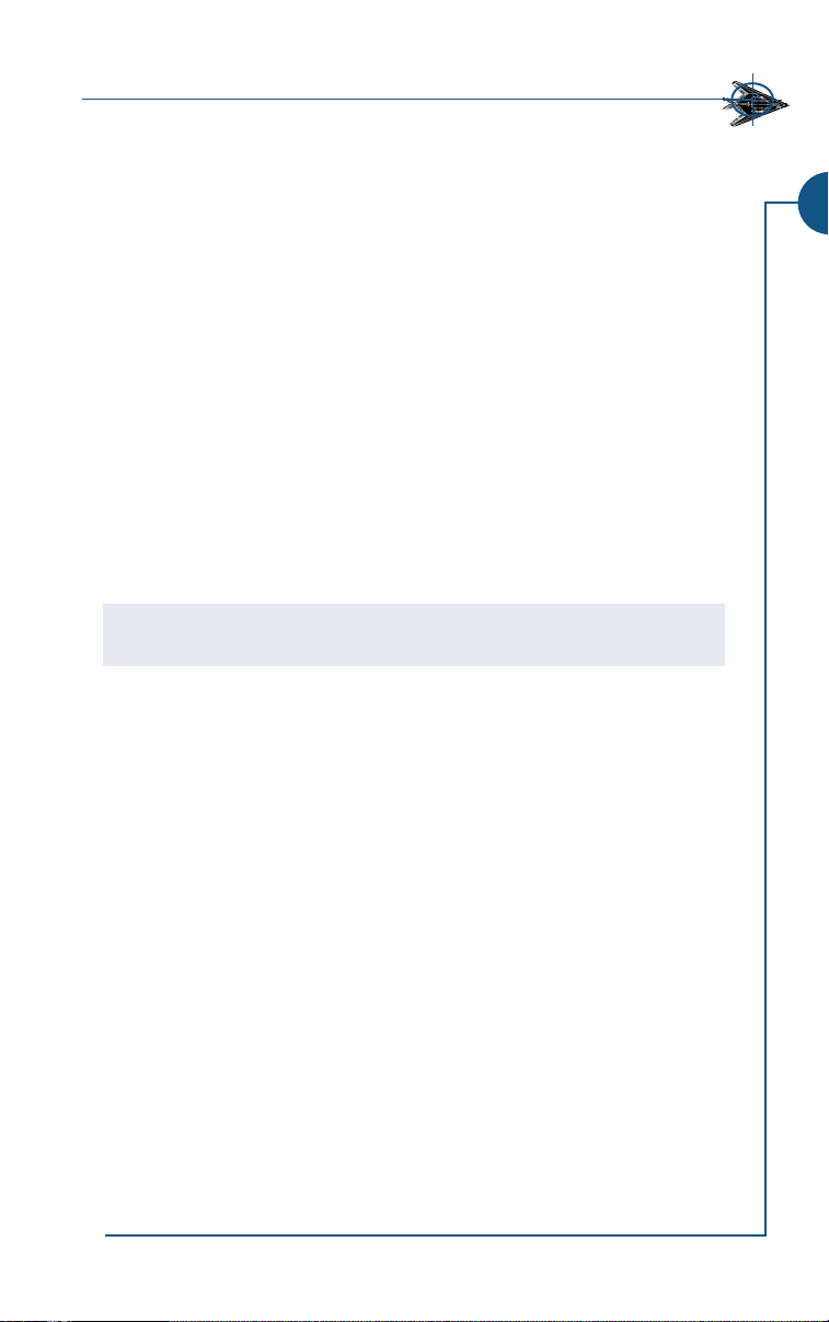
Drop-Down Pilot Window
In the top right-hand corner of each screen is a button
for a drop-down pilot window. The name displayed
on the button is your currently selected pilot. Click on
the button to view this pilot’s current stats. Click
again to close the window.
Go to the Pilot Records screen to view more in-depth
information about the currently selected pilot, change
his photo, select a different saved pilot or create a new
pilot. See Pilot Records Screen, p. 1.26.
Menu Button
At the bottom of nearly every screen is a MENU button
which gives you access to all of the interface screens.
Click on an option to go to that screen.
Instant Action
Fly Now Jump straight into flight. See p. 1.4.
Flights
Quick Mission Create and fly a customized mission. See p. 1.5.
Training Fly a training mission. See p. 1. 8.
Single Mission Fly a pre-scripted, single mission, a mission you created, or
a future campaign mission you’ve already won. See p. 1.9.
Campaigns Start or rejoin a campaign. See p. 1.10.
Multiplayer Start a multiplayer game. See 5: Multiplayer, p. 5.1.
Tools
Pilot Records View pilot statistics and change pilots. See p. 1.26.
Mission Recorder Review recorded missions. See p. 1.33.
Reference Prepare with Jane’s reference information. See p. 1.35.
Web Check out relevant web sites. See p. 1.36.
Preferences
Set graphics, sound, game controls, keyboard, and gameplay options. See
Appendix D: Preferences, p.8.8, for full documentation of these features.
Jane’s USAF
Main Menu
Return to the Main Menu. See p. 1.3.
Quit
Exit the game.
1.2
Page 5
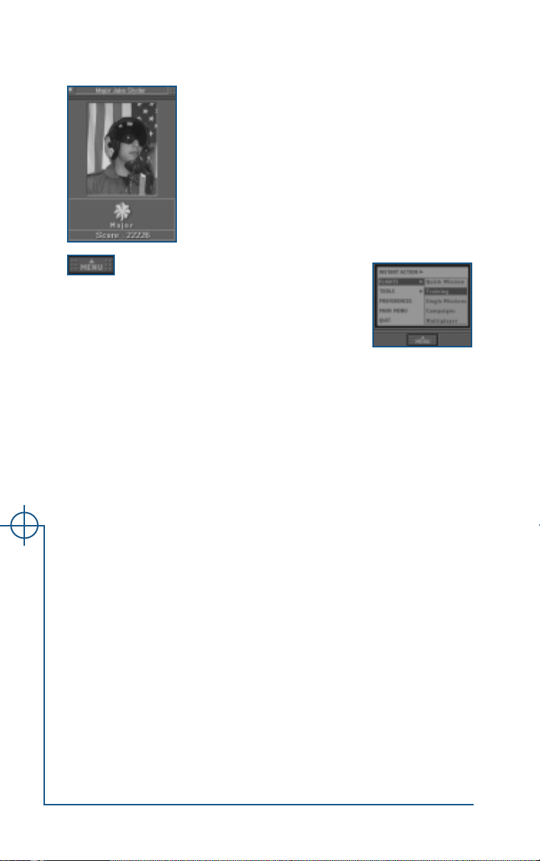
MAIN MENU SCREEN
From the Main Menu screen, you can access all other interface screens and
view data for your currently selected pilot.
To return to this menu from any other interface screen, click on the
button at the bottom of the screen and choose MAIN MENU. Or, click the link
at the top of any pre-flight screen.
Link back to this screen
(appears in all screens)
MENU
1. INTERFACE
Fly Now,
p. 1.4
Information
window
Show main
menu option
Drop-down
pilot window,
p. 1.2
Links to
other
screens,
p. 1.4
Show Main Menu Option
When the box marked SHOW MAIN MENU WHEN STARTING USAF at the bottom of
the Main Menu screen is checked, you will begin at the Main Menu screen. This
happens whenever you start the game using the Jane’s USAF shortcut or
choose Play USAF from the Windows 95/98 Start menu. If this box is
unchecked and you enter in one of the ways listed above, you will begin the
game where you left off. (You will always begin the game in the cockpit of a
randomly generated mission when you click the Fly Now shortcut icon on
your desktop.)
Information Window
When you run Jane’s USAF for the first time, a customized welcome message
appears in this box in the lower center of the screen. It recommends an initial
mission type based on the gameplay level you selected during installation.
When you subsequently return to this screen, your current pilot’s stats
appear in this window.
Whenever you position the cursor over a link on the screen, information
about that link replaces the information in this window.
1.3
Page 6

Fly Now
The large FLY NOW button in the center of the Main Menu screen takes you
directly to the cockpit of one of the eight flyable aircraft, in the middle of an
air-to-air scramble.
To get an idea of your situation, you can of course use all of the instruments
normally available to you in the cockpit — such as your radar, RWR, etc. For
a brush-up on instrumentation, see the Cockpit chapter, p. 2.1-2.48.
You can also take a look at the real-time Tactical Display screen by pressing q.
This screen shows the movement of all friendly and enemy aircraft in each area,
as well as relevant ground objects. You can zoom in on areas, object and
flights, and click
Display screen, p. 1.15, for more details.
Note: Fly Now missions do not count toward your currently selected pilot’s kill tally,
statistics, score and rank (see Pilot Records Screen, p. 1.26).
VISIT for a camera’s-eye view of some objects. See Tactical
Links to Other Screens
Move the mouse over a link to highlight it. A short description of the link
appears in the information window in the lower center of the screen. Leftclick on the link to go to the corresponding screen.
The page references below indicate where to turn in this manual for more
information on each link.
Quick Mission p. 1.5
FLIGHT
SCREENS
TOOL
SCREENS
Jane’s USAF
Training p. 1.8
Single Missions p. 1.9
Campaigns p. 1.10
Multiplayer Multiplayer, p. 5.1
Pilot Records p. 1.26
Mission Recorder p. 1.33
Reference p. 1.35
Web p. 1.36
Preferences Appendix D,p. 8.8
Quit Exit the game.
1.4
Page 7
FLIGHT SCREENS
The flight screens allow you to choose or create a mission to load and fly. All
are available from both the Main Menu screen and the
bottom of all preflight screens (see Main Menu Screen, p. 1.3 and MENU
Button, p. 1.2). Flight screens include:
Quick Mission Editor Set basic mission parameters to create a custom
mission that you can fly immediately.
Training (p. 1.8) Fly a pre-scripted mission designed to teach you
flight skills, weapons use or combat tactics.
Single Missions (p. 1.9) Fly a pre-scripted, single mission, a mission you creat-
ed, or a future campaign mission you’ve already won.
Campaigns (p. 1.10) Fly a series of related missions.
You can also jump directly into a randomly generated air-to-air battle by click-
FLY NOW button on the Main Menu Screen. See Fly Now, p. 1.4.
ing the
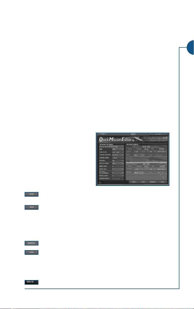
Quick Mission Editor Screen
The Quick Mission Editor allows
you to quickly design a customized
mission. You determine what goes
into the mission, and the computer
places all of the objects for you.
Quick Missions will not count
toward your currently selected
pilot’s kill tally, statistics, score, and
rank (see Pilot Records Screen, p.
1.26).
Open a Quick Mission that you have previously created and saved
using the Quick Mission Editor.
Save the current Quick Mission. You can later open this mission.
Quick Mission files are saved by default in Program Files\Jane’s
Combat Simulations\USAF\Resource\Missions\Qme. (You can
move these missions to any other computer, as long you copy them
into this same directory.) Finally, you can access your Quick
Mission by selecting My Missions from the Single Mission screen.
Have the computer generate Quick Mission Editor settings for you.
Load the Quick Mission you have created. A pop-up window
appears, tracking the progress of the load; if you wish to cancel,
click the
screen. Once the mission is loaded, you will begin it from the
Tactical Display screen (see p. 1.15).
Go back to the previous screen.
CANCEL button to go back to the Quick Mission Editor
MENU button at the
1. INTERFACE
1.5
Page 8

Mission Settings
You will set general parameters for your mission in the
box on the left side of the screen. Note that Quick
Missions are modeled on USAF Red Flag missions in that
USAF pilots fly against each other on “red” and “blue”
sides. You always start out on the blue side, leading the
Austin flight.
Note: In multiplayer games, you can switch sides before you fly by jumping into a red
side flight. (Click the CORVETTE or DODGE flight button at the bottom Tactical
Display screen — see Switching Aircraft/Flights, p. 1.21, for details.) Once you
are in flight, however, you can’t switch sides.
Mission Name Type in a name for the mission. This name will appear
under My Missions in the Single Mission screen.
For the following options, choose a setting from the pull-down menu:
Area
Time of Day DAWN
Starting Position HEAD-ON (both sides begin the mission facing each other)
Starting Range
Weapons GUNS ONLY (loadouts limited to guns)
VIETNAM, IRAQ, GRAND CANYON or GERMANY
(determines the terrain you will fly over)
, DAY, DUSK or NIGHT
TAIL-ON-BLUE (red begins the mission on blue’s tail)
TAIL-ON-RED (blue begins the mission on red’s tail)
5
MILES,10MILES, 20MILES, OR30MILES
(Determines how far apart the red and blue forces are)
AA (default loadout consists of air-to-air weapons)
AG (default loadout consists of air-to-ground weapons)
AA & AG (default loadouts consist of air-to-air and air-
to-ground weapons)
Note: Guns are available in every loadout selection. Additionally, you can always use
guns for either air-to-air or air-to-ground attacks. The options above limit only the
missile and bomb ordnance loaded on aircraft.
USAF A/G Target
Jane’s USAF
Enemy SAMs
CONVOY, SAM SITE, RUNWAYS or NONE
(Establishes a ground target for the blue side)
0, 1, 2or3
(Sets the number of SAM sites on the red side)
Enemy AAAs
0, 1, 2or3
(Sets the number of AAA sites on the red side)
1.6
Page 9
Revivals
This sets the number of times aircraft on both the red and blue sides can
regenerate. If you fly the blue side, the settings below apply to the red side.
If you jump to the red side, the settings below apply to blue.
No. of Revivals
Revival Delay
0, 1, 2, 3
0, 10
, or UNLIMITED
SECONDS, 20SECONDS or1MINUTE
Weapon Reload CURRENT LOAD (plane regenerates with whatever weapons
it had left when it was destroyed)
RELOAD ALL
(plane regenerates with full, original loadout)
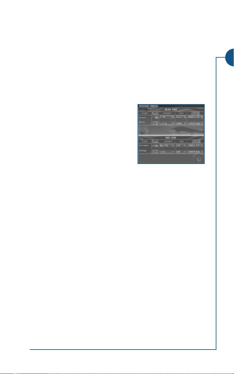
Mission Forces
In the box on the right side of the screen you
will configure the flights for the blue and red
sides. Each side has a maximum of two flights
— Austin and Buick flights are always blue and
Corvette and Dodge are always red.
You can set the following for each flight:
0 / 1
No. of Planes Click the menu to select the number of aircraft —
2/ 3/4
. The Austin flight must contain at least 1 air-
craft. All other flights have a minimum of 0.
Aircraft F-16, F-
16
C, F-15C, F-15E, F-
F-105D and MIG-16 through MIG-
117
A, F-4E, F-22A, A-10A,
29
.
(Scroll down the menu to see all available options. The
blue side can fly any player-controllable aircraft, while
the red side can fly any aircraft.)
, CAS or STRIKE
Task
CAP
(See Tasking Section, p. 1.18, for definitions.)
Starting Altitude RUNWAY,
1000
FT. AGL,
5000
FT. AGL, or
15000
FT. AGL.
/
1. INTERFACE
1.7
Page 10
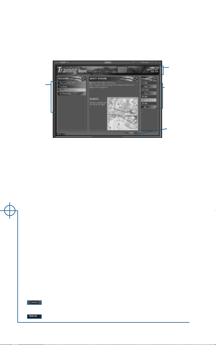
Training Screen
Jane’s USAF has a variety of training missions covering the basics of flying, airto-air combat and air-to-ground combat. Training missions count toward
your currently selected pilot’s kill tally, statistics, score, and rank (see Pilot
Records Screen, p. 1.26).
Choose a
course
Choose a
mission
Choosing a Course
The training series is made up of three courses: Basic, Weapons School and Red
Flag. Click on a training course in the upper right corner of the screen to
select it. The currently selected course is highlighted.
BASIC. Covers basic flight skills — taking off, landing, refueling, and training.
WEAPONS SCHOOL. Provides hands-on experience with various weapons sys-
tems in different environments. These missions are based on the actual USAF
Weapons School curriculum, and have been enhanced for this game.
RED FLAG. Red Flag is the Air Force’s air combat training program. These train-
ing missions feature more advanced scenarios designed to prepare fighter pilots
for grueling air-to-air combat. They are only available to pilots who have
reached the rank of 1st Lieutenant. For more information on USAF’s Red Flag
program and its history, see Background: Operation Red Arrow, p. 6.24.
Flying a Mission
The Missions box on the left of the Training screen lists the missions available
in the currently selected course. Click on a mission to select it. Information
about the mission — including the mission objective, the flights participating in the mission and a map of the mission area — appears in the About
Mission window in the center of the screen.
Jane’s USAF
The Planes box on the right of the screen lists the aircraft that you can fly for
the selected mission. Click on an aircraft to select it.
Once you have selected your mission and plane, click
the mission and display the Tactical Display Screen (see p. 1. 15).
Go back to the previous screen.
Choose an
aircraft
Load the
mission
LOAD to load
1.8
Page 11

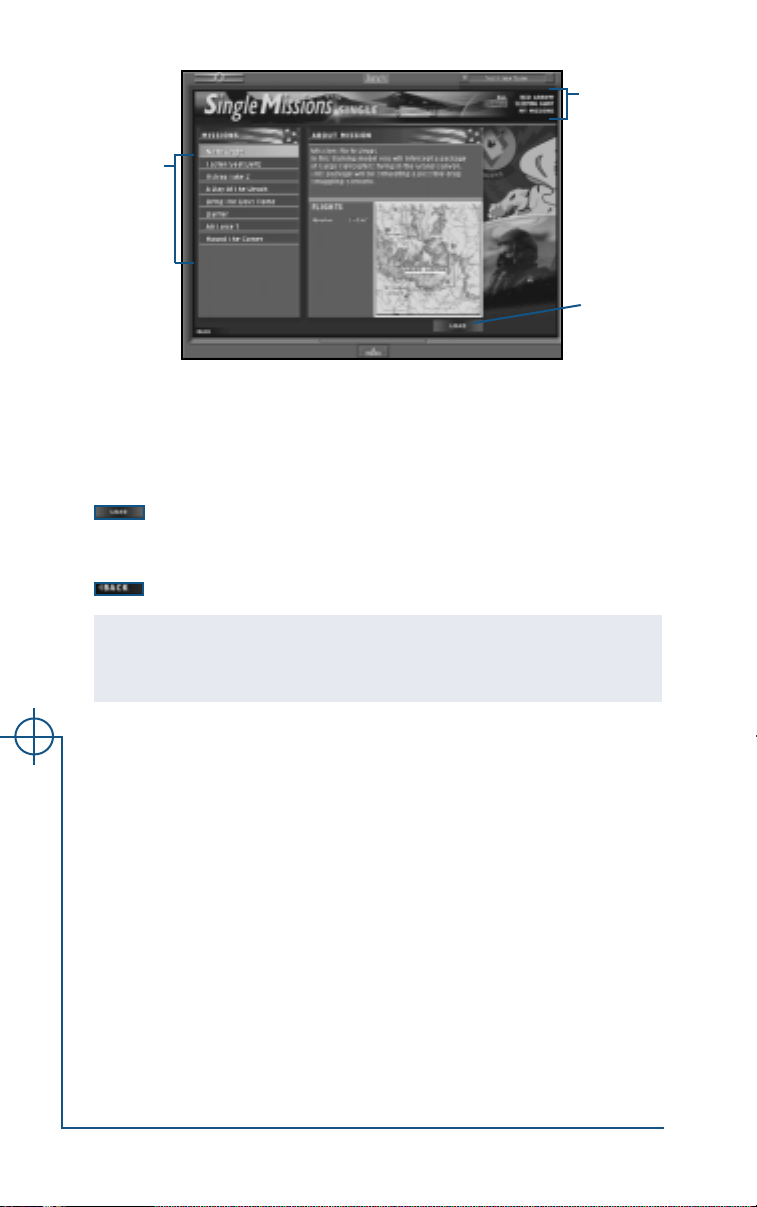
Single Missions Screen
Single missions include:
• Several pre-scripted single missions that are not part of any campaign
• Missions you have already completed in one of the futuristic campaigns
(Operation Red Arrow and Operation Sleeping Giant)
• Missions you’ve created and saved with the Quick Mission Editor
( p. 1.5) or User Mission Editor (UME). (See Start > Program > User
Mission Editor (UME) Manual.)
Listing Available Missions
The text options in the top right corner of the screen control which missions
are displayed in the Missions box on the left. The currently selected option
is highlighted in light blue.
ALL. List all available single missions. (None count toward campaign out-
comes, some count toward currently selected pilot’s record — see SINGLE
below.)
SINGLE. List single missions that are not part of any campaign. These are the
only missions that count toward your currently selected pilot’s record (i.e.,
kill tally, statistics, score and rank).
OPERATION RED ARROW. As you complete missions in this campaign, they
become available on this screen so that you can refly them. (None count
toward campaign outcome or pilot’s record.)
OPERATION SLEEPING GIANT. As you complete missions in this campaign, they
become available on this screen so that you can refly them. (None count
toward campaign outcome or pilot’s record.)
MY MISSIONS. List of missions you designed and saved using the Quick
Mission Editor (see p 1.5) or User Mission Editor (see Start > Program >
User Mission Editor (UME) Manual). None count toward pilot’s record.
1. INTERFACE
Important Note: Most single missions flown from this screen do not count toward
your currently selected pilot’s record (i.e., kill tally, statistics, score and rank). The
exceptions are standalone single missions that are not also a part of any campaign
(see notes above). Likewise, missions that are also part of campaigns do not count
toward the outcome of the campaign when flown from this screen as single missions.
Missions you’ve created with the Quick Mission Editor or User Mission Editor will not
affect pilot statistics.
For more information on what counts toward a pilot’s record, see Pilot Records
Screen, p. 1.26.
1.9
Page 12
List
available
missions
Choose a
mission
Load the
mission
Choosing a Mission
Click on a mission in the Missions box on the left side of the screen to select
it. (Use the scroll bar on the right edge to scroll the list.) The currently selected mission is yellow. Information about that mission appears in the About
Mission box on the right.
Load the currently selected mission. A pop-up window will show
the progress of the load; click the
you want to stop loading and return to the Single Missions screen.
Go back to the previous screen.
Note: Once you click FLY at the bottom of the Tactical Display screen, you’ve begun the
mission. If you quit without successfully completing your mission objectives, you will have
failed the mission. (You can refly missions as often as you like.)
CANCEL button on this pop-up if
Once the mission has loaded, you will begin the mission pre-flight, at the
Tactical Display screen (see Tactical Display Screen, p. 1.15).
Campaign Screen
Jane’s USAF offers four campaigns. Two historical campaigns are taken
directly from the conflict in Vietnam and Operation Desert Storm. One
futuristic campaign (Sleeping Giant) is a fictional conflict set in Germany.
The other futuristic campaign (Red Arrow) consists of dogfighting with MiG
fighters, air-to-air operations, and air-to-ground operations in the continental US.
Jane’s USAF
In the historical campaigns you can access all missions at any time. In the
future campaigns, you must successfully complete each mission to advance
to the next. Campaign missions count toward your currently selected pilot’s
kill tally, statistics, score, and rank (see Pilot Records Screen, p. 1.26).
For background reference information on the campaign scenarios, see the
Background: Campaigns, pp 6.10-6.28.
1.10
Page 13
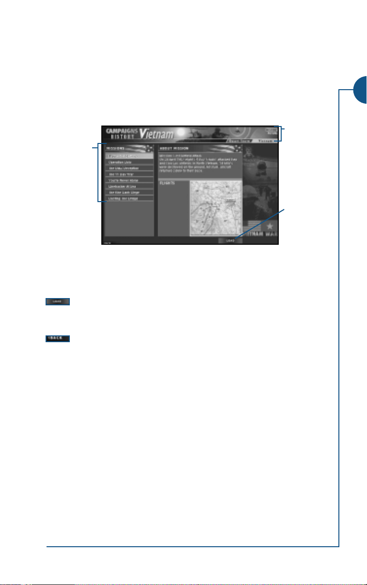
Starting or Rejoining a Historical Campaign
The text options in the top right corner of the screen control which missions
are displayed in the Missions box on the left side of the screen. The currently
selected option is highlighted in gold.
HISTORY Display the DESERT STORM
DESERT STORM Display Desert Storm campaign missions in the Missions box.
VIETNAM Display Vietnam campaign missions in the Missions box.
Choose a
mission
Click on a mission in the Missions box on the left side of the screen to select it.
(The currently selected mission is yellow.) Information about that mission
appears in the About Mission box on the right. All missions are available at all
times, and you can fly missions in any order.
Load the currently selected mission. A pop-up window will show
the progress of the load; click the
you want to stop loading and return to the Campaigns screen.
Go back to the previous screen.
You begin the mission pre-flight, at the Tactical Display screen (see p. 1.15.)
and VIETNAM tabs.
Select
campaign
Load
mission
CANCEL button on this pop-up if
1. INTERFACE
Winning Historical Campaigns
To win the campaign, you must successfully complete every mission in that campaign. When you do, you will be awarded the Vietnam Service Medal (for Vietnam
campaign) and the Kuwait Liberation Medal (for Desert Storm campaign).
• To pass a mission, you must achieve all of your mission objectives and either
quit when prompted, or (if you choose to continue flying) land safely.
• If you quit out before completing your objectives, you will fail the mission.
This won’t affect your pilot’s score, but the mission’s status will be “Failed.”
• You can re-fly historical campaign missions as often as you like from the
Campaign screen. You can win the campaign by passing missions that
you’ve previously failed.
• Once you have passed a mission, its status will remain “Passed.” This is
true even if you fly it later and fail it.
1.11
Page 14
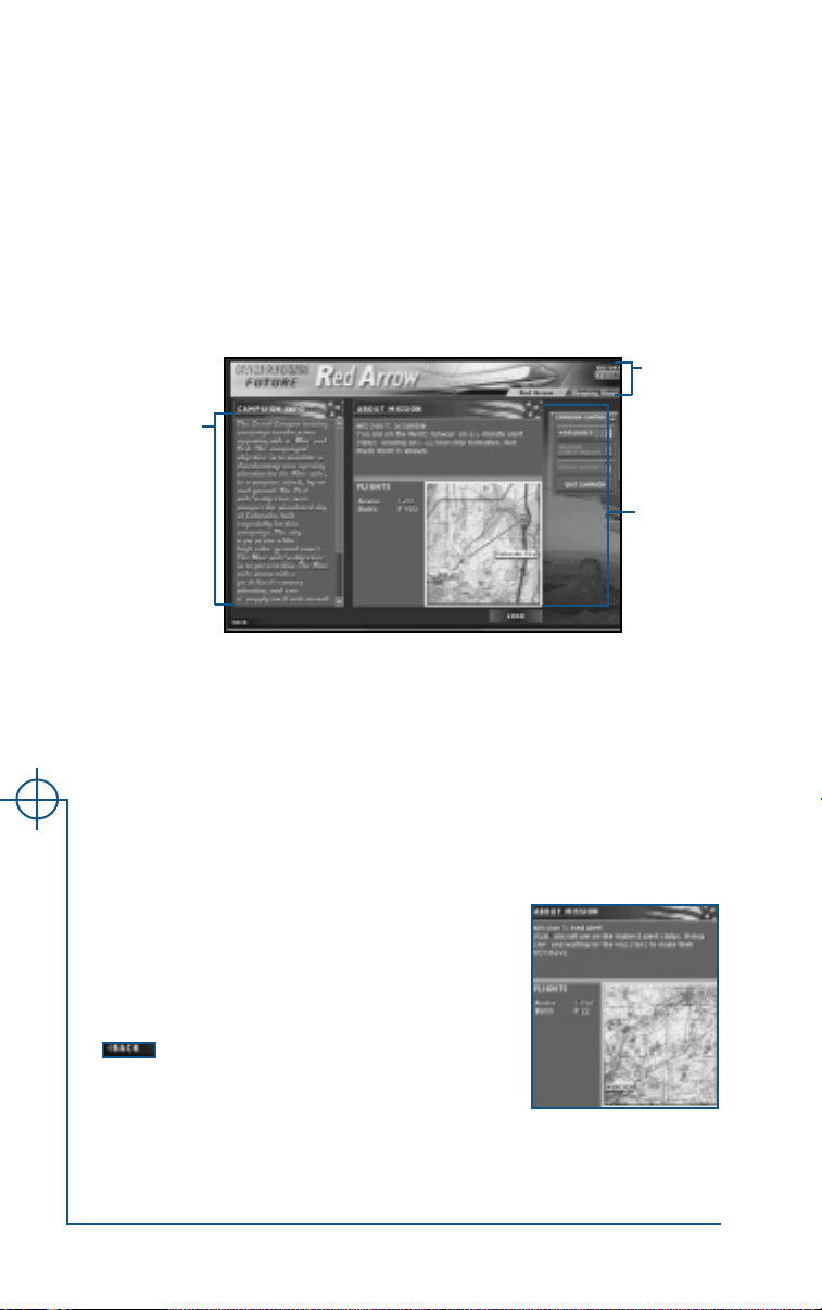
Starting or Rejoining a Future Campaign
The text options in the top right corner of the screen control what is displayed in the box on the left side of the screen. The currently selected option
is highlighted in gold.
FUTURE Display SLEEPING GIANT and RED ARROW tabs.
OPERATION
RED ARROW
OPERATION
SLEEPING
GIANT
Campaign
Info box
In both futuristic campaigns, you must closely manage your pilots, aircraft
and weapons. At least one time (possibly two times) during each campaign,
you’ll need to fly weapon and supply missions (see facing page).
Display information about the current state of the futuristic
Grand Canyon campaign.
Display information about the current state of the futuristic
Germany campaign.
Select
campaign
About
Mission box
Campaign Info Box
The Campaign Info box on the left side of the screen displays information about
the overall state of the campaign. A text box explains overall goals and summarizes the situation; use the scroll bar to the right to scroll through this text.
About Mission Box
The About Mission box displays information about
the mission you are about to undertake, including a
brief textual explanation of the situation, a list of the
flights assigned to the mission, and a map of the
overall mission area.
Jane’s USAF
Go back to the previous screen.
1.12
Page 15
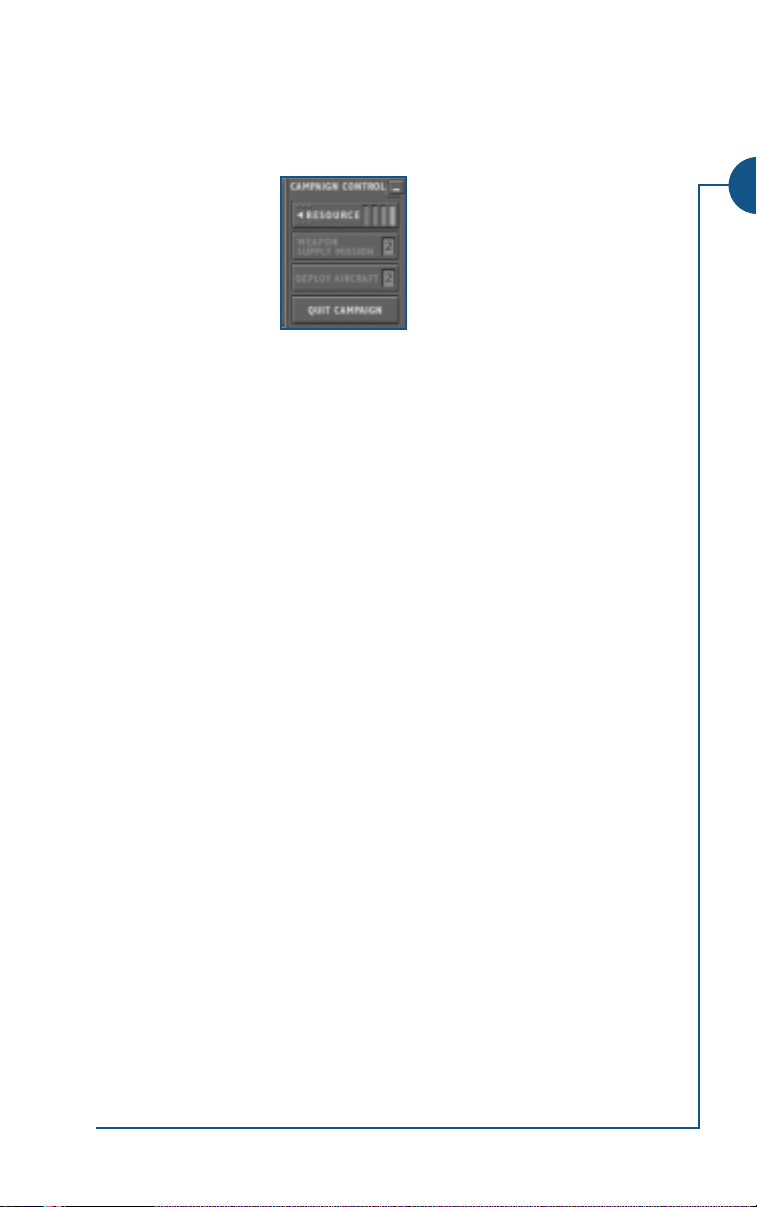
Campaign Control Window
When you start a future campaign, a small window appears onscreen. The
Campaign Control window has four buttons that let you view information
about your remaining aircraft and weapon resources.
RESOURCE Open the Resource Status window.
WEAPON
SUPPLY
MISSION
DEPLOY
AIRCRAFT
QUIT
CAMPAIGN
The
you’re running low on aircraft, pilots or weapons and can’t finish the campaign without restocking. You can fly up to two missions of each type. If either
option is grayed-out, you’ve either used up all available missions of that type,
or you’re not running low yet.
Click to fly a Supply mission. Becomes available when you do
not have enough ordnance to complete the campaign. The number remaining is the number of Supply missions you have left.
Click to fly a Deploy mission. Becomes available when you do
not have enough planes and pilots to complete the campaign.
The number remaining is the number of Deploy missions you
have left.
Quit the campaign and return to the Main Menu screen.
WEAPON SUPPLY MISSION and DEPLOY AIRCRAFT options are only available if
1. INTERFACE
Deploy Aircraft/Weapon Supply Mission
Over the course of the campaign, your resources will dwindle as you expend
ordnance, lose aircraft and possibly lose pilots. When your resource levels
are too limiting, you may need to fly a Deploy Aircraft or Weapons Supply
mission.
You can fly each of these missions only twice. (This is true for both the futuristic Sleeping Giant and Red Arrow campaigns.)
1.13
Page 16
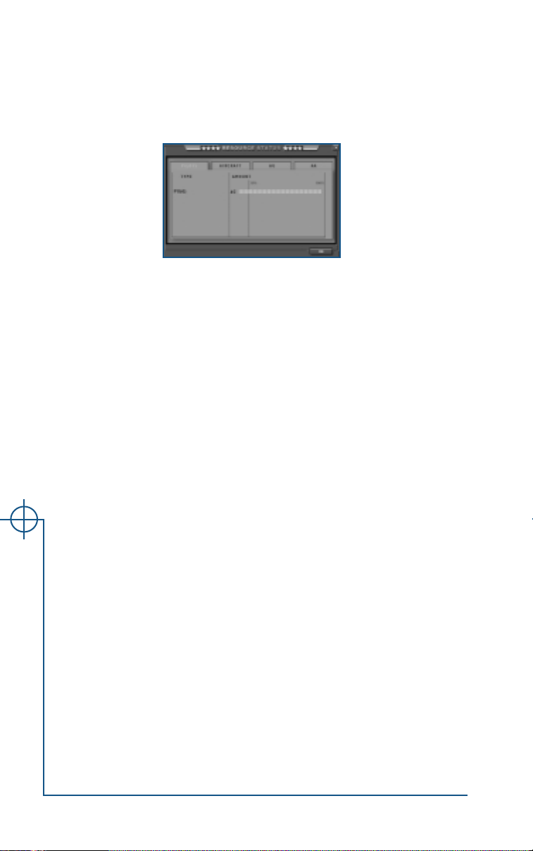
Resource Status Window
This window charts the resources available to you at the current state of the
campaign. Click on the tabs at the top of the window to view the current status of the corresponding resource(s):
nance) and AA(air-to-air ordnance).
For each resource, the following is listed:
Type. Breaks down resources by designation (i.e., AGM-65, MK-82, etc. for
AG ordnance)
Amount. Lists the number of this resource type currently available to you.
The green bar beside the number illustrates the amount remaining as a percentage of the amount you started with.
PILOTS, AIRCRAFT, AG (air-to-ground ord-
Winning a Futuristic Campaign
You will win a futuristic campaign when you have successfully completed all
of the missions in that campaign.
• You must successfully complete each mission to advance to next one.
• To pass a mission, you must achieve all of your mission objectives and either
quit when prompted, or (if you choose to continue flying) land safely.
• If you quit out of a mission before completing your mission objectives, you
will fail the mission. This won’t affect your pilot’s score, but you will have
to refly the mission successfully before you can advance to the next one.
• Once you’ve passed a mission, it will be available from the Single Missions
screen. When flown as single missions, they will not count toward the outcome of the campaign.
Jane’s USAF
1.14
Page 17
MISSION SCREENS
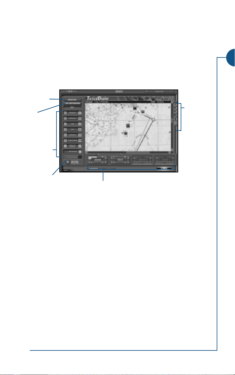
Tactical Display Screen
The Tactical Display screen is available within every mission — both before the
mission, when it displays your mission briefing and the target area, and during the mission, when it displays a real-time aerial view of mission events. All
functionality described in this chapter is available both before and during
flight unless otherwise indicated.
Briefing,
p. 1.16
Map
Navigator,
p. 1.19
Map icon
buttons,
p. 1.19
Record
button,
p. 1.33
MENU Click the gray MENU button at the bottom of the screen to return
Flight/aircraft buttons, p. 1.20
to any other screen.
(If you are in flight, you will see a prompt asking if you want to end
the mission. Click NO if you want to continue your current mission.
YES to end the mission and continue to the interface screen
Click
you’ve selected.)
LOADOUT (Not available during flight.) Click the blue LOADOUT button to go
to the Loadout screen. Use this screen to adjust your weapons load.
See Loadout Screen, p. 1.22.
VISIT (Not available before flight.) Click this button to jump to a close-
up camera view of a selected object. See Visit, p. 1.21 for details.
FLY When you are ready to fly (or return to the cockpit view if you are in
flight) click the FLY button in the bottom right corner of the screen.
BACK Click this button to return to the previous screen (the last one you
visited).
Map tools,
p. 1.16
1. INTERFACE
1.15
Page 18
Before a Mission
After your Quick, Single, Campaign or special Multiplayer mission has loaded,
the Tactical Display screen displays your briefing for that mission, including a mis-
sion area map and information about waypoints, threats and flight selection.
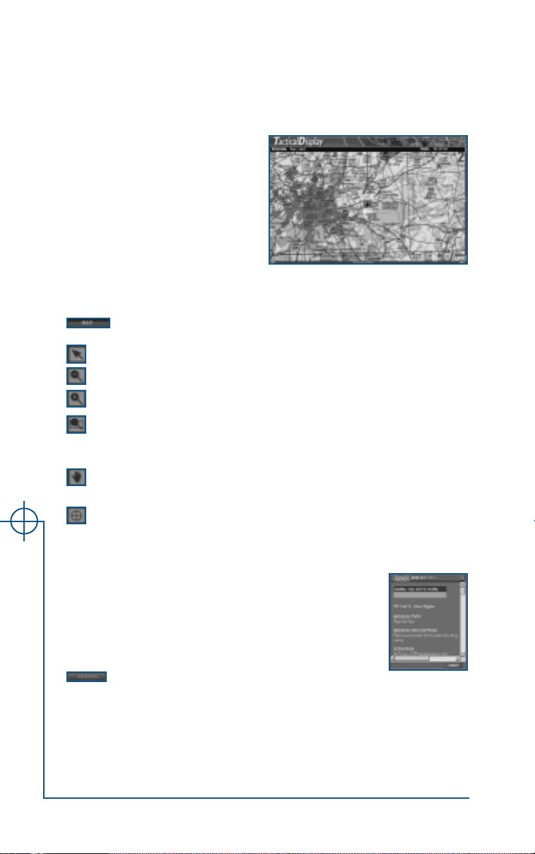
Map and Map Tools
The largest frame on the Tactical
Display Window displays a map of the
mission area, along with the name of
the mission and the mission time.
You can scroll the map using the
scroll bars on the bottom and right
edges of the map. You can also move
the map with the Map Tools.
By default these tools appear at the right of the map; however, you can click
and drag them anywhere on the screen.
Toggle map display. (Map is visible by default.)
Changes your cursor back to normal function (an arrow-shaped cursor)
Click this icon to zoom the map out
Click this icon to zoom the map in
Click this icon to change the cursor to a cross hair with a box
attached. Use the cursor to draw a box around an area of the map to
zoom in to that area.
Click this icon to change the cursor to a hand. Use the hand cursor
to click and drag the map, moving it around.
Click this icon to change the cursor to a cross hair. Click on the map
with the cross hair to center the map where you’ve clicked.
Briefing Window
The briefing lists the mission name and type, with a brief
description of the situation, weather, available intelligence,
flight tasking, objectives, safety concerns and helpful tips.
You will want to pay particular attention to the
Intelligence, Flight Tasking and Mission Objectives sections.
Click the
Jane’s USAF
• Click the
• Click the X button at the top of the window to close the window.
the Tactical Display Screen to open a gray Briefing
window on top of the map.
1.16
BRIEFING button in the top left corner of
PRINT button at the bottom of the window to print your briefing.
Page 19
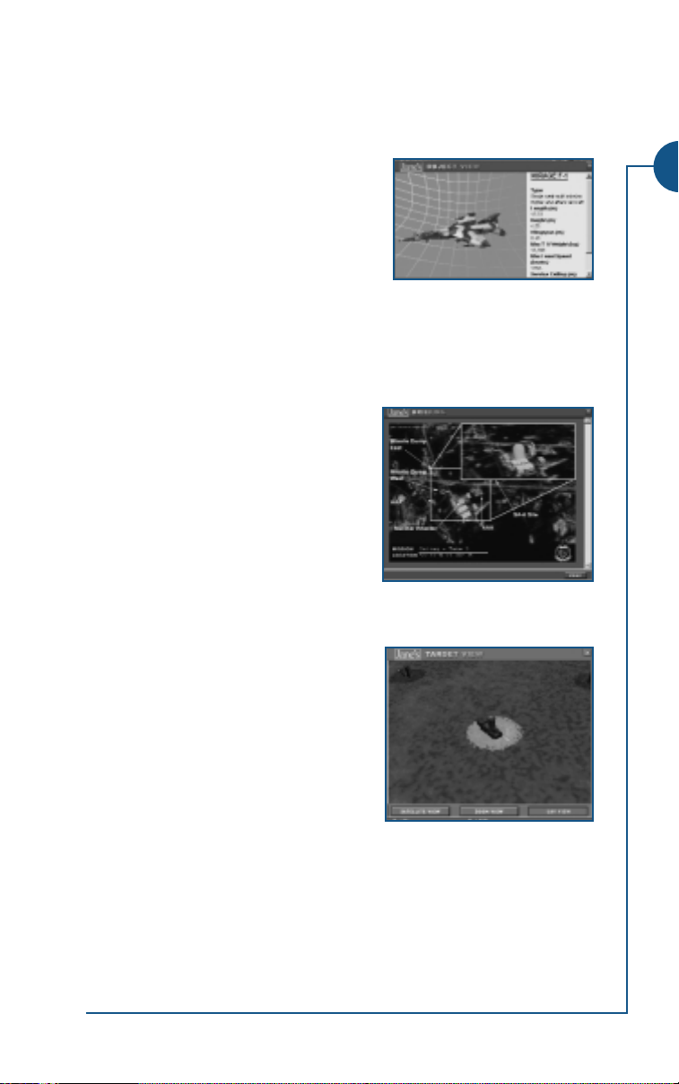
Intelligence Section
This section of your briefing lists your targets and all known threats in the
area. (The threats listed may not be the only threats!). Light-blue, underlined
text indicates a hotlink to additional reference windows.
Object View windows. Pop-up Object View
windows display a 3D model of the threat or
target and list specifications from Jane’s
Information Group, Ltd.
• Use the arrow keys on the keyboard to
rotate the model.
• Use the scroll bar at the left edge of the window to scroll through the
Jane’s text.
• Click the
Target Photo windows. For some targets, a
link to pop-up Target Photo window may be
provided. These photos give an overall view
of the target area with exact location coordinates. An enlarged view of the target area
may also be provided, with structures called
out to help you recognize you specific target
elements once you reach the area.
• Click-and-drag this window to resize or
move it.
X button at the top of the window to close it.
1. INTERFACE
Target View windows. These windows dis-
play live footage of the target area (and
therefore cannot be printed out). Use the
buttons at the bottom of the window to
change views.
SATELLITE VIEW Switch to an overhead view
of the target area from an
intelligence satellite.
ZOOM VIEW Switch to a zoomed-in
version of the above view. Rotate the view using A and S.
UAV VIEW Switch to a rotating, 3D view of the target from the camera
on an Unmanned Aerial Vehicle (UAV) flying over the target
area. UAVs are small, remotely controlled airplanes used for
surveillance, target tracking and bomb damage assessment.
• Click the
X button at the top of the window to close it.
1.17
Page 20

Tasking Section
List each flight in the mission, along with the number and type of aircraft in
each flight, and each flight’s task and targets. As in the intelligence section,
light-blue, underlined text marks hotlinks to additional reference windows.
A brief overview of tasks is listed below.
CAP. (Combat Air Patrol) Fly around a specified waypoint or along a specified path in search of aircraft threats. Often performed in support of another mission element that is executing a ground strike.
CAS. (Combat Air Support) Fly to the specified target area and strike tanks,
ground artillery, troops and other enemy ground force elements. This task is
always performed in support of friendly ground force elements operating
within or near the target area.
Escort. Defend a specified friendly unit(s) from enemy attack as it travels
through its waypoints. Escort missions are generally performed in support of
friendly air elements that are executing the main mission objective. The
objective of the mission is to keep the escorted aircraft out of harm’s way.
Intercept. Neutralize an attack by enemy aircraft, such as fighters that are
attempting to interfere with a mission, or bombers that have targeted a
friendly ground installation.
SEAD. (Suppression of Enemy Air Defenses) Destroy enemy AAA and SAM
sites, and perhaps ground control radar installations to clear a path for
another strike force. Target types include surface-to-air missile sites, anti-aircraft artillery batteries and any associated radar systems.
Strike. Fly to the specified target area and strike specified targets. Targets
might include anti-air sites, storage or production facilities, radar installations, and other strategic structures. Sometimes strike operations are performed in support of another air element — for example, to destroy enemy
AAA and SAM sites to clear a path for another strike force. Sometimes they
are the mission’s main strategic objective.
Note: In Jane’s USAF, you are responsible for completing every flight’s task (see
Flight/Aircraft Buttons, p. 1.20). Make sure you note which flight is responsible
for which task — the aircraft assigned to it and their weapons loadout will probably
be best suited to the task it has been given. For example, if two F-15Cs are assigned
to fly a CAP for A-10s on a ground strike, the slow low-flying A-10s would have
extreme difficulty taking over the air-to-air role and the F-15Cs probably wouldn’t
have the loadout for the ground work.
Jane’s USAF
Mission Objectives
Pay very close attention to the information listed in this section. Here you
will be told exactly what you are responsible for in the mission.
1.18
Page 21
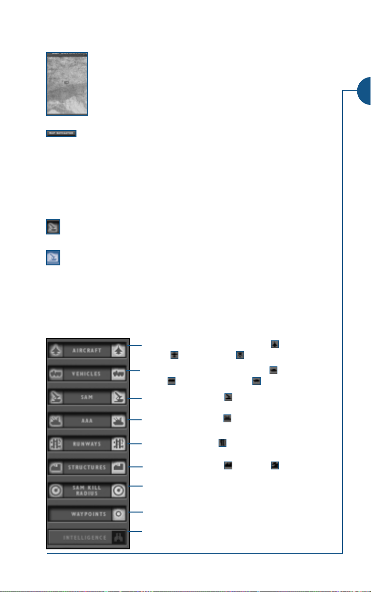
Map Navigator Window
This window displays an overview map of the mission area. The
portion of the map currently displayed in the main window of
the Tactical Display screen is marked by a red box. You can click
and drag this red box inside the Map Navigator window to control which portion of the map is displayed in the larger window.
Click the
also press the
X button at the top of the window to close it. (You can
MAP NAVIGATOR button to close it.)
Click the map navigator button (second button on the left) in the
Tactical Display screen to open and close the Map Navigator window.
Map Icon Buttons
The rest of the buttons to the left of the map control what mission elements
are displayed on the map. Each button (except
consists of red and blue icon buttons (that can be lit or dark) and a gray text
button (that can be raised or depressed).
(red) Click the red icon buttons to display/hide only enemy objects
of this type.
(blue) Click the blue icon buttons to display/hide only friendly
objects of this type.
When the icon buttons are lit, the objects are displayed; when they are dark,
the objects are hidden.
Click the text buttons listed below to hide/display all objects of that type.
When a button is depressed, the corresponding objects are displayed. When
a button is raised, the objects are hidden.
WAYPOINTS and INTELLIGENCE)
1. INTERFACE
Display/hide aircraft, including fighters , support
aircraft , and helicopters .
Display/hide vehicles, including tanks ,
trucks , and armored vehicles .
Display/hide SAM sites .
Display/hide AAA sites .
Display/hide runways
Display/hide structures and radar .
Display/hide SAM kill radii. These circles indicate
the effective range of each SAM site.
Display/hide your waypoints.
Superimpose a window with troop locations and
arrows indicating troop movement over the map.
1.19
Page 22

Flight/Aircraft Buttons
The flight and aircraft buttons at the bottom of the screen allow you to center the map on different friendly flights or aircraft. In missions flown by more
than one flight, you can also use these buttons to jump from flight to flight.
Click on a flight text button (
control of that flight. The map will re-center on the flight’s current
location, and the flight button turns yellow.
Click on the numbered aircraft icon buttons to re-center the map
on that aircraft. (This does not affect which flight you are in.) The
button for your aircraft is green, all other aircraft buttons are blue.
Human pilots will always lead a flight of computer wingmen. Aircraft 1 is
always the flight leader.
Note: You cannot change flights in basic or weapons training missions.
AUSTIN, BUICK, CORVETTE, etc.) to take
Record Mission Button
Use the Record Mission feature if you’d like to record the mission you are
about to fly and view it later in the Mission Recorder screen (see Mission
Recorder Screen, p. 1.33). When the red, circular button is depressed and the
red light is illuminated, you are recording. You can stop recording at any time
by clicking the button again. You can’t turn mission recording on/off once the
mission has begun, however. Only in-flight actions will be recorded — your
Tactical Display screen actions, for instance, won’t show up on the final tape.
Toggle the mission recorder on/off
In-Flight
You can also access the Tactical Display screen while flying by pressing q.
• The game keeps running while you are viewing the Tactical Display screen.
• The Loadout screen is unavailable in-flight.
• To switch to another flight, click the center button of that flight, then click
• If you want to end the mission while in flight, press cQ. You can also
go to the Tactical Display screen, the click the
of the screen and choose any option.
Note: If you end a mission before you have successfully completed your mission objectives you will fail that mission.
Jane’s USAF
Real-Time Map Display
While in-flight, the map window displays the movement of all mission elements in real time. The map tools and map icon buttons function exactly as
they do when you are on the ground, allowing you to move and zoom the
map and hide or display different mission elements (see Map and Map
Tools, p. 1.16 and Map Icon Buttons, p. 1.19).
1.20
MENU button at the bottom
FLY.
Page 23
Visit
Use the VISIT button to view any mission element — including ground forces,
target structures and both enemy and friendly planes. Alternatively, doubleclick on any icon.
To visit an object:
• Click on an icon to select the object you want to look at.
Click the
K Move the mouse to rotate the view around the object.
- /+ Zoom view in and out.
q Return to Tactical Display screen.
VISIT button at the bottom of the screen.
Switching Aircraft/Flights
During a mission, you can use the flight and aircraft buttons at the bottom
of the Tactical Display screen to jump into different aircraft or flights. You must
finish the objectives for all flights, not just the one you fly initially. For this reason, you
may want to spend time fine-tuning loadouts for each flight before you take
off — that way, you’ll be prepared for whatever the mission holds in store.
Press a flight button to jump to a different flight, if one is available. You must always fly the lead aircraft (aircraft 1) unless it is
destroyed during a mission. Then you will fly lead in the next available aircraft (aircraft 2, then 3, then 4).
Press an aircraft button to center the map around that aircraft.
• If your aircraft is destroyed during a mission and you are flying with at
least one other friendly, you will automatically jump to the Tactical Display
screen, where you can choose a new aircraft.
• You must complete the mission objectives for all flights to win a mission.
As soon as you successfully complete one flight’s objectives, you can continue in either your aircraft or select another flight and take over its mission. The mission won’t end until all flights’ mission objectives have been
completed or all mission aircraft have been destroyed.
1. INTERFACE
• Press s1, 2, 3, or 4 to switch to Flights 1, 2, 3 or 4 without using
the Tactical Display screen. The mission won’t end until all flights’ mission
objectives have been completed or all mission aircraft have been
destroyed.
• To manually end a mission, press cQ. Or, click the
bottom of the Tactical Display screen and choose any option. You will fail
the mission if you end it before completing your objectives.
MENU button at the
1.21
Page 24
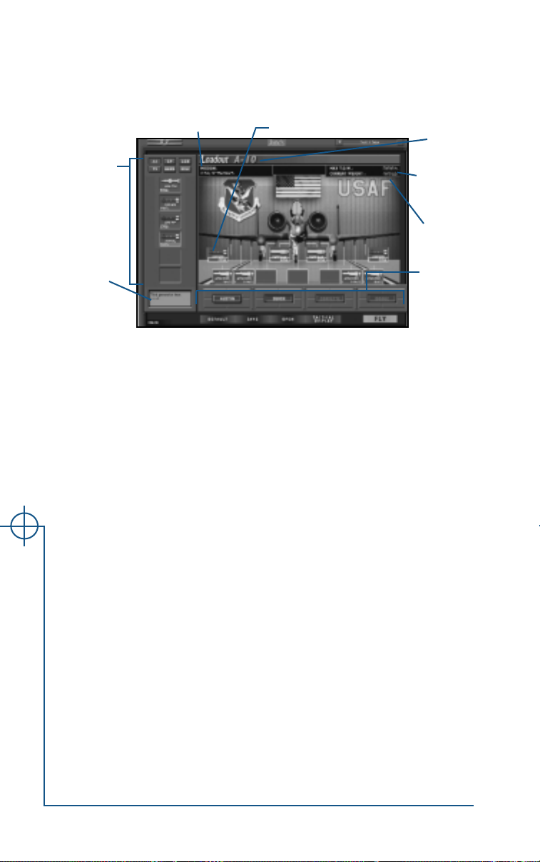
Loadout Screen
Click the LOADOUT button at the bottom of the Tactical Display screen to go to
the Loadout screen and customize weapons load for all flights in your mission.
Available
Current mission
weapons/
equipment
Hardpoint
Current
aircraft
Maximum
take-off
weight
Current
weight
Description
of item
currently
under cursor
DEFAULT Return to the default loadout for the currently selected flight (see
Flight/Aircraft Buttons, p. 1.20).
SAVE Save the current loadout to your hard drive in order to use it later.
You may want to set up a custom loadout for use against a specific target type, or a loadout that best utilizes your weapon delivery
skills. Another advantage to saving custom loadouts is that it considerably speeds up the process of setting up a multiplayer game.
Loadout files (*.ldt) are specific to the type of aircraft for which
they were created (F-22, F-15, etc.). By default, loadouts are saved
under Program Files\Jane’s Combat Simulations\USAF\
Resource\Loadouts\<name of aircraft>. (This path will be different if you did not install the game to the default location.)
OPEN Open a saved loadout. Loadouts are specific to a type of aircraft —
the game will automatically point you to the folder in which loadouts for your currently selected aircraft type are stored by default.
TACTICAL Return to the Tactical Display screen. If you have made any changes
DISPLAY to a loadout, you will be prompted, “Use Loadout?” Click YES to
keep the changes or
FLY Enter flight. If you have made any changes to a loadout, you will
Jane’s USAF
be prompted, “Use Loadout?” Click YES to keep the changes or NO
NO to lose the changes.
to return to the Tactical Display screen.
BACK Click this button to return to the Tactical Display screen.
Flight/
aircraft
buttons
1.22
Page 25

Customizing a Loadout
Choosing a Flight
All aircraft in a flight carry the same weapons and equipment: when you
reconfigure this plane’s loadout, you are reconfiguring the loadout for all
aircraft in the currently selected flight.
Select the flight for which you want to view a loadout.
The currently selected flight’s button is yellow.
Viewing Available Weapons/Equipment
The box on the left side of the screen displays all weapons available to the
currently selected aircraft. Weapons availability is limited by the type of aircraft you are flying (not all weapons can be loaded on all aircraft) and in
some missions — particularly campaign missions — the number and types of
stores available at the current stage of battle.
Six buttons across the top of this box control which type of stores are displayed in the box:
AA Display available air-to-air weapons (e.g., AIM-120)
GP Display available unguided, general purpose bombs (e.g., Mk-82)
LGB Display available laser-guided bombs (e.g., GBU-10)
TV Display available TV-guided bombs (e.g., AGM-65)
HARM Display available HARM weapons (e.g., AGM-88)
MISC Display available guidance and ECM pods and fuel tanks (e.g., ALQ-119)
When you place your cursor over a displayed weapon or equipment pod, a
brief description of that item appears in the text box at the lower left corner
of the screen.
For more information on the different weapons, see Combat: Using
Weapons, p. 4.28. For more information on different targeting systems, see
Combat: Targeting, p. 4.23.
1. INTERFACE
1.23
Page 26

Loading and Unloading Equipment
The box on the right side of the screen contains a picture of the currently
selected flight’s aircraft with all hardpoints called out. The aircraft designation (e.g., F-15C, F-22) is listed at the top of the box.
Weapons that appear inside the hardpoint boxes are currently
loaded on the aircraft. The number of weapons loaded onto that
hardpoint and their total weight are listed beneath the weapon.
Blank hardpoint boxes denote empty hardpoints.
Tactical Considerations
Many tactical considerations affect your loadout. You will need to review your
briefing, determine which kinds of targets and/or threats you are likely to face,
and load effective weapons. For ground strike missions, the level of precision
required for the strike should also influence your weapon choice. Weather conditions may also affect your choice of weapons — IR-seeking missiles are more
effective at night, but TV-guided weapons may be useless. You may also need
to load additional targeting and sensor pods to use certain types of weapons.
See Combat: Using Weapons, p. 4.28, for more information on weapons.
Load and Unload Equipment
• To load, click an item in the available weapons/equipment box and drag it to
a hardpoint. This loads the maximum number you can carry on the hardpoint.
• You can load an item onto a hardpoint that is already loaded — the new
item will replace the old one.
• To unload, right-click on a hardpoint (or click on the item on the hard-
point and drag it off). Each right-click unloads a single weapon.
• If you have a weapon loaded onto a hardpoint, you can left-click on the
hardpoint to add another weapon of the same kind, up to the maximum
number that the hardpoint will hold.
• Hardpoints are generally designed to carry certain types of weapons or
equipment. You won’t be able to successfully mount an item to a hardpoint that cannot carry it. Try dragging the item to a different hardpoint.
Usable hardpoints have yellow outlines that appear when you select a certain weapon, while unusable hardpoints have white outlines.
Weight and Balance
When you are customizing a loadout, pay attention to weight and balance.
• The current aircraft’s Max T.O.W. (maximum takeoff weight) and Current
Jane’s USAF
Weight are listed above the aircraft. The current weight must be less than
the max T.O.W. weight, or the flight will never make it off the runway.
• If your load is not evenly balanced on both wings (i.e., heavier on one wing
than the other), a red warning light appears at the top center of the screen.
Equalize the weight by adding or removing weight from the opposite wing.
1.24
Page 27
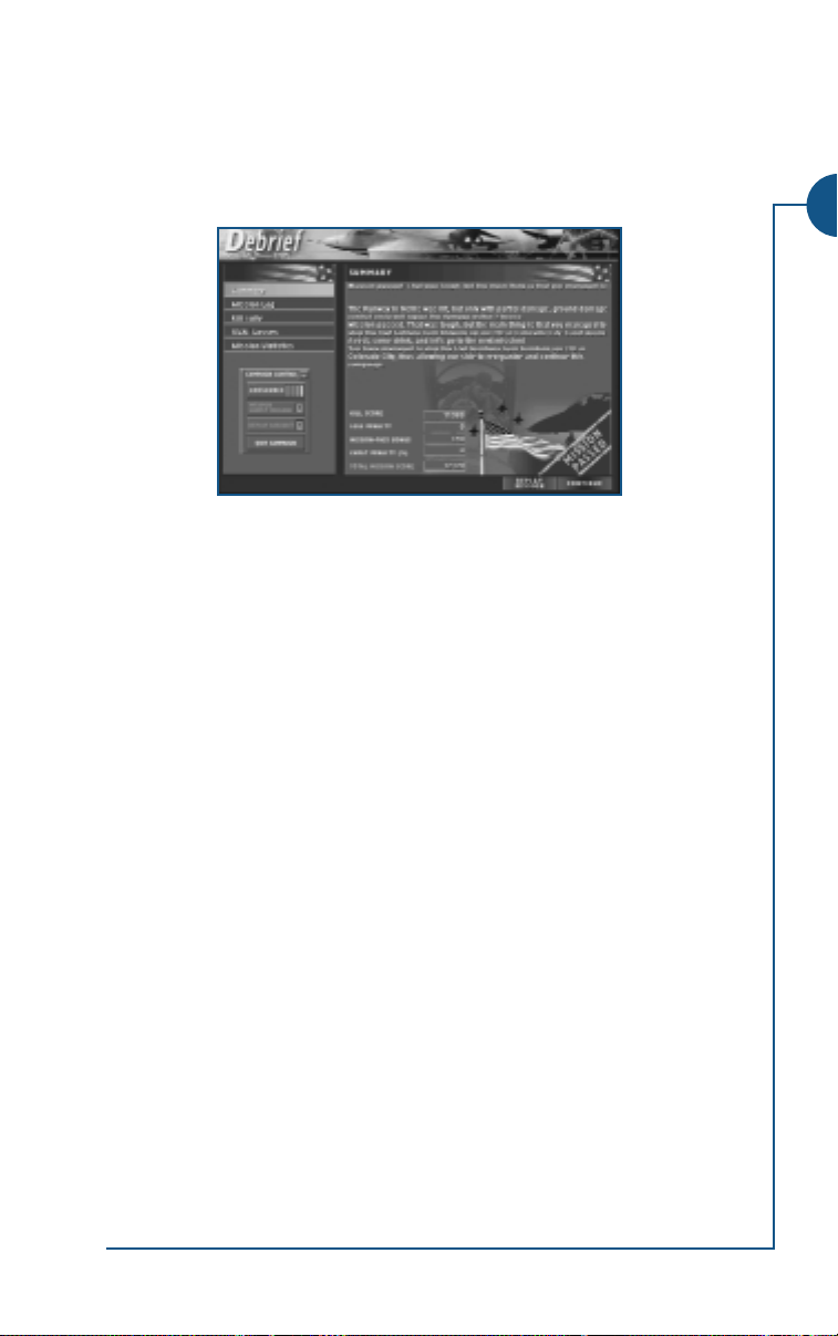
Debrief Screen
Once you have completed a mission (successfully or unsuccessfully) you will
see the Debrief screen. The Debrief screen gives a summary and statistics for
your performance during the mission. Click the text buttons on the left side
of the screen to display the corresponding information on the right.
SUMMARY. Sums up the results of the mission.
MISSION LOG
green contributed positively (or neutrally) to the mission; events listed in red
contributed negatively.
KILL TALLY
task force, along with a tally of your personal kills. The total points for the
task force kills are tallied on the right.
USAF LOSSES. For aircraft, lists total losses and number of friendly kills (i.e.,
aircraft killed by friendly fire). For ground forces and structures, lists those
killed by friendly fire, and total losses. Points deducted for friendly losses are
tallied on the right.
MISSION STATISTICS. Summarizes your performance in each plane that you flew
— your total flight hours, number of kills and kill/loss ratio in those planes
— and then list your totals in these categories. Click on the buttons beneath
the table to view:
Once you have finished viewing your stats, click REPLAY MISSION to fly the mission over or
mission (Single, Quick Mission, etc.).
If you recorded the mission, a RECORDED MISSION button also appears. Click
this to go to the Mission Recorder screen and review your mission.
. Gives a chronological log of mission events. Events listed in
. Lists all enemy aircraft, ground forces and structures killed by the
PERFORMANCE PER PLANE CHART
. Graphs the kill/loss ratio for each air-
craft in this mission. Each bar represents a single aircraft. The height of
the bar reflects the kill/loss ratio, which is equal to the total number of
kills divided by the number of times that aircraft was destroyed.
LOSS ANALYSIS CHART. Displays a pie chart that shows the cause of your
loss during the mission — a crash, enemy air-to-air missile, SAM, etc.
CONTINUE to return to the screen where you selected/created the
1. INTERFACE
1.25
Page 28

TOOLS SCREENS
Pilot Records Screen
From the Pilot Records screen, you can view the stats of your current pilot,
load a saved pilot and create and delete pilots. Click the text buttons in the
box to the left of the screen to call up the corresponding window. (The currently selected button is yellow.)
Go back to the previous screen.
Pilot Dossier
The Pilot Dossier window displays basic statistics for your currently selected
pilot. You can also use this area to change your current pilot, create new
pilots and delete those you no longer need from this window.
Changing Your Current Pilot
To select a pilot, choose the pilot’s name from the drop-down menu. The
currently selected pilot will be available to fly when you leave the Pilot Records
screen. (He won’t appear in the drop-down pilot window until you leave this
screen — see Drop-Down Pilot Window, p. 1.2.)
Creating a New Pilot
NEW PILOT Create a new pilot. Type the pilot’s name and callsign in the
Jane’s USAF
pop-up window that appears and click OK.
Deleting a Pilot
REMOVE PILOT Delete currently selected pilot.
1.26
Page 29
Current Pilot Information
The following statistics are displayed in the Pilot Dossier window.
Callsign/Name. Display current pilot’s name and callsign.
Photo. Displays a picture of your current pilot. A default photo is provided
for you.
IMPORT If you would like to replace the default photo with another image,
click the
IMPORT button, then locate the image on your hard drive
and click OPEN. The image must be in bitmap (.bmp) format.
Rank. Shows your pilot’s current rank insignia. The current rank reflects all Single,
Campaign and Training missions that this pilot has flown. See Rank, p. 1.31.
Pilot score, Number of missions flown and Total flight hours. The totals
for your current pilot, tallied from all pre-scripted missions the pilot has
flown (i.e., Single, Training and Campaign missions).
Your current pilot’s performance in Quick Mission and Fly Now missions
does not affect these statistics. The only exception occurs when you host a
multiplayer game using this pilot in a cooperative mission (but not in any
other type of multiplayer game).
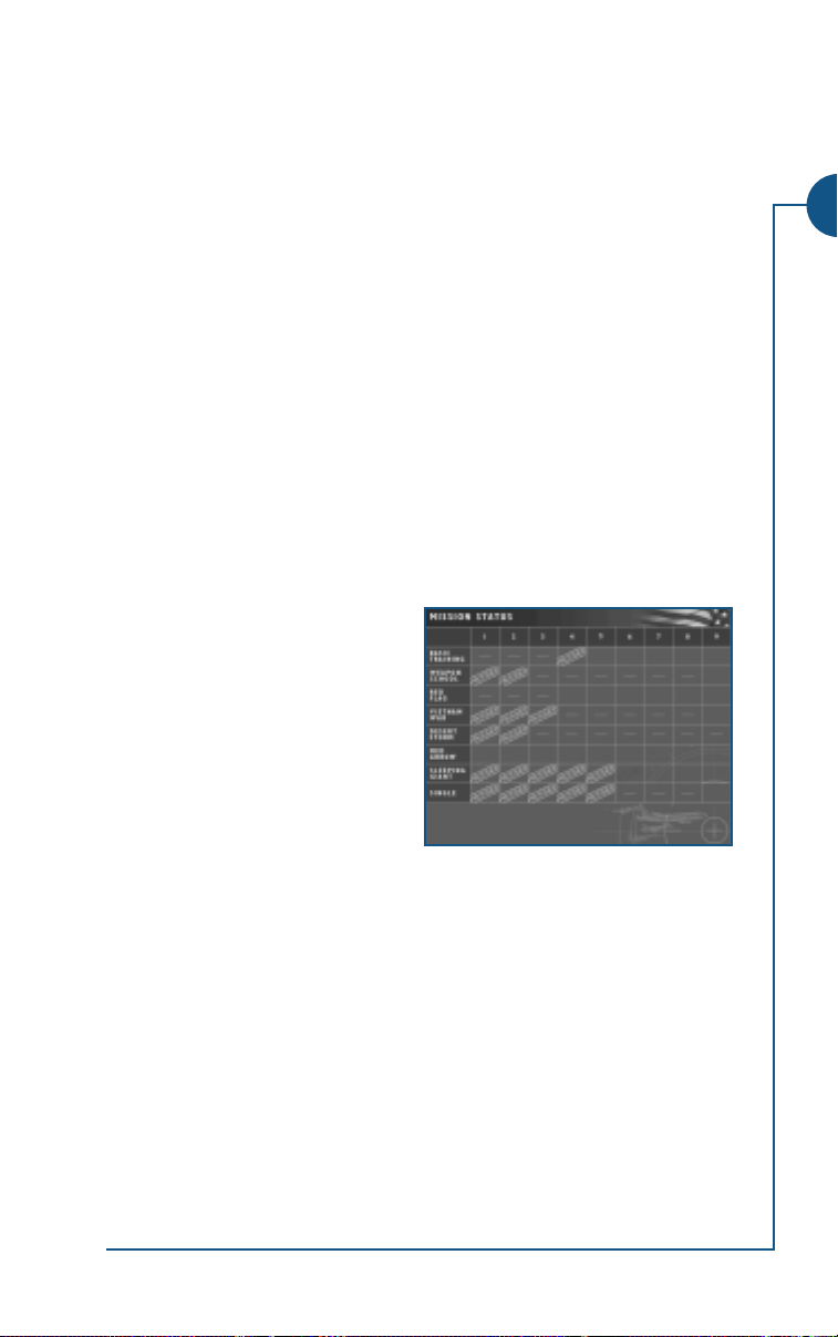
Mission Status
The Mission Status window charts the
currently selected pilot’s success and
failure in pre-scripted missions on a
mission-by-mission basis. Mission
series are listed on the left; mission
numbers are listed across the top.
Mission 1 is the first mission in a
series, mission 2 the second, and so
forth.
The series are as follows:
BASIC TRAINING, WEAPON SCHOOL and RED FLAG = training mission series
•
VIETNAM WAR, DESERT STORM, RED ARROW and SLEEPING GIANT = campaign
•
mission series
• SINGLE = single missions that aren’t also part of a campaign.
FAILED status indicates you quit the mission or lost all friendly force aircraft
A red
before successfully completing all of your mission objectives. A green PASSED sta-
tus indicates you successfully completed all of your mission objectives.
1. INTERFACE
1.27
Page 30
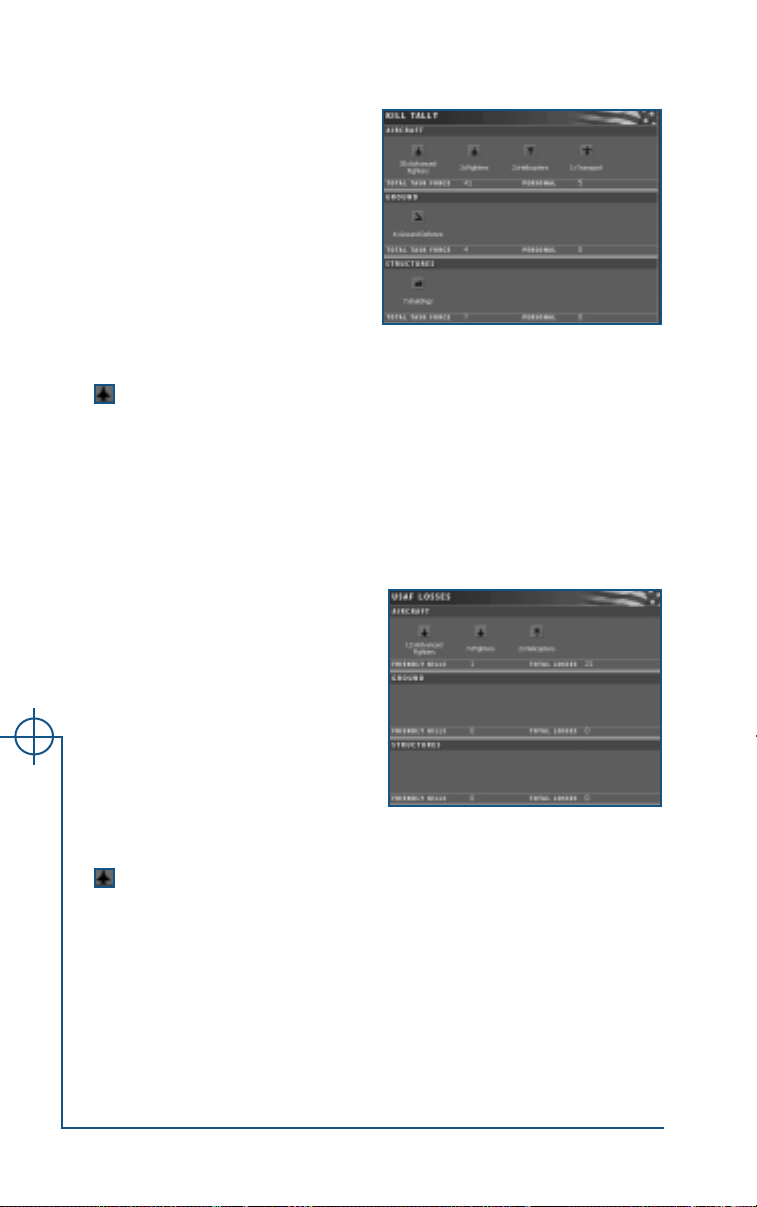
Kill Tally
The Kill Tally window lists the enemy
aircraft, ground forces and structures you have destroyed, broken
down by object type. The kills listed
are for all pre-scripted missions the
current pilot has flown (i.e., Single,
Training and Campaign missions).
Your current pilot’s performance in
Quick Mission and Fly Now missions
does not affect these statistics. The
only exception occurs when you host a multiplayer game using this pilot in a
cooperative mission (but not in any other type of multiplayer game).
(red) Represents objects destroyed by friendly forces. The desig-
nation and number of objects are listed beneath the icon.
TOTALTASKFORCE Lists the number of aircraft, ground forces or structures
destroyed by friendly sides.
PERSONAL Lists the number of aircraft, ground forces or structures
destroyed by your current pilot.
USAF Losses
The USAF Losses window is similar in
format to the Kill Tally window. It lists
the friendly aircraft, ground forces
and structures destroyed during all
pre-scripted missions flown by your
current pilot (i.e., Single, Training and
Campaign missions).
Your current pilot’s performance in
Quick Mission and Fly Now missions
does not affect these statistics. The
only exception occurs when you host a multiplayer game using this pilot in a
cooperative mission (but not in any other type of multiplayer game).
(blue) Represents objects destroyed by friendly forces. The desig-
nation and number of objects are listed beneath the icon.
FRIENDLY KILLS Lists the number of friendly aircraft, ground forces or
structures destroyed by other friendly forces.
Jane’s USAF
TOTAL LOSSES Lists the total number of friendly aircraft, ground forces
or structures.
1.28
Page 31

Pilot Statistics
The Pilot Statistics window tracks your
pilot’s performance in different types
of aircraft and over time.
Charts your current pilot’s performance in each type of aircraft, including
FLIGHT HOURS, the KILLS ACHIEVED and
his
KILL/LOSS RATIO in that aircraft. Totals in
the these three categories are then listed below this chart.
Click the buttons below the chart to
view the following graphs:
PERFORMANCE PER PLANE CHART
. Displays a chart listing the kill/loss ratio for
each aircraft during the pilot’s overall career. Each bar represents a single
aircraft. The height of the bar reflects the kill/loss ratio, which is equal to the
total number of kills divided by the number of times you were destroyed.
LOSS ANALYSIS CHART
. Displays a pie chart that shows the cause of your loss
during the mission — a crash, enemy air-to-air missile, SAM, etc.
SKILL LEVEL CHART. View a graph of how your kill level has increased/decreased
as you have gained additional flight hours with this pilot. (A steady climb
would indicate that as your experience increases, so does your lethalness.)
Weapon Statistics
The Weapons Statistics window records
the number and types of weapons
you’ve fired, hit percentages, kills
achieved and weapons fired per kills.
Click on the
down by class of weapon (air-to-air
missiles, air-to-air guns, etc.). Click
on the
down by weapon designation (AIM7F, MK-82, etc.).
The following stats are listed for each category:
TOTAL FIRED The total number of this type of weapon that your cur-
HIT PERCENTAGE The percentage of released weapons of this type that
TOTAL KILLS ACHIEVED Number of targets destroyed by weapons of this category.
WEAPON FIRED PER KILL
BASIC tab to see a break-
ADVANCED tab to see a break-
rent pilot has released.
hit their targets (both guided and unguided).
Average number of weapons in this category fired to
make a kill.
1. INTERFACE
1.29
Page 32

Mission Statistics
The Mission Statistics window shows performance statistics broken down by
mission category. Click on the text buttons to select a category (the currently selected button is yellow).
ALL View stats for all pre-scripted missions (Training, Single
and Campaign).
BASIC TRAINING View stats for the basic training series of Training mis-
sions (see Training Screen, p. 1.8).
WEAPON SCHOOL View stats for the weapon school series of Training mis-
sions (see Training Screen, p. 1.8).
RED FLAG View stats for the Red Flag series of Training missions
(see Training Screen, p. 1.8).
DESERT STORM View stats for the Desert Storm campaign series (see
Campaigns Screen, p. 1.10).
VIETNAM WAR View stats for the Vietnam War campaign series (see
Campaigns Screen, p. 1.10).
SLEEPING GIANT View stats for the Sleeping Giant (Germany) campaign
series (see Campaigns Screen, p. 1.10).
RED ARROW View stats for the Red Arrow (Grand Canyon) campaign
series (see Campaigns Screen, p. 1.10).
SINGLE View stats for the series of Single missions that are not also
part of a campaign (see Single Missions Screen, p. 1.9).
In each category, the following statistics are given:
TOTAL SORTIES Number of missions in this category that your current
FLOWN
MISSION SUCCESS Percentage of these missions that were successful
PERCENTAGE
AVERAGE MISSION
SUCCESS TIME plete a mission
MINIMUM MISSION Fastest time in which pilot has successfully completed a
SUCCESS TIME mission
AVERAGE AA KILLS Average number of air-to-air kills pilot makes in a mission.
PER MISSION
MAXIMUM AA KILLS
Jane’s USAF
PER MISSION
AVERAGE AG KILLS
PER MISSION mission
MAXIMUM AG KILLS Highest number of ground objects kills pilot destroyed in
PER MISSION a mission
pilot has flown
Average time current pilot requires to successfully com-
Highest number of air-to-air kills pilot made in a mission
Average number of ground objects pilot destroys in a
1.30
Page 33

Rank
The Rank window provides a record of your pilot’s promotional history, listing the RANKS and insignia he has earned, and the point in his career when he
earned each rank (FLIGHT HOURS AT PROMOTION and MISSION).
When you complete a mission,
you receive a mission score. Once
your pilot accumulates enough
points, that pilot will receive a promotion. You’ll find out about any
promotions in the Debrief Screen,
p. 1.25. To view a pilot’s current
rank, look at his Pilot Record,
p. 1.26. Rank also appears in the
upper right corner of all pre-flight
screens.
Note: If you score enough points during a mission for a promotion, but you fail the
mission, you won’t be promoted. You’ll get to keep your points, and the promotion
will be awarded the next time you pass a mission.
Ranks (in order received) Points
2nd Lieutenant 0
1st Lieutenant 5000
Captain 15,000
Major 25,000
Lt. Colonel 45,000
Colonel 70,000
Brigadier General 100,000
Major General 130,000
Lt. General 160,000
General 200,000
1. INTERFACE
1.31
Page 34

Medals
See the Install Guide for more details on scoring and medals.
When you complete certain parts of the game
and/or surpass a certain
score, your pilot will
receive a medal. You can
view your pilot’s current
medals (as well as all
potential medals) in the
Pilot Records Screen, p.
1.26. Click on the name
of a medal to display it.
The medals in the game are modeled after actual US Air Force decorations.
For the sake of preserving some element of suspense and surprise, specific
mission and score requirements are not listed here. You can receive specific
medals for accumulating a certain score, and campaign medals for completing each individual game campaign.
Mission Medals/Patches
Red Flag Participant Patch
Medal of Honor
Air Force Cross
Silver Star
Distinguished Flying Cross
Air Medal
• As with promotions, you won’t receive a medal in any mission that you fail.
• You can only earn one medal of one type for a particular mission — even
if you replay that same mission and score enough points for a second
medal, you won’t receive one for that mission again.
• You can receive multiple medals of the same type.
• You can’t receive any medals while flying on the red side.
• You don’t receive any medals for any of the training missions.
• It is possible to be awarded both a mission medal and a campaign medal
when completing a mission.
Jane’s USAF
• You can collect multiple medals for completing the same future campaign
more than once. (This is only true for future campaigns.)
Air Force Achievement Medal
USAF Vietnam Service Medal
USAF Emirate of Kuwait Liberation Medal
Red Arrow Medal
Sleeping Giant Medal
1.32
Page 35

Mission Recorder Screen
Before beginning a mission, you
have the option of recording it by
clicking the Record Mission button
on the Tactical Display screen. (See
Tactical Display Screen, p. 1.15)
You can load, view and save these
recorded missions with the Mission
Recorder screen. Missions can be
played back in the Recorder screen,
as well as in full-screen mode.
Finally, you can send these missions
to other players for viewing.
Recorder Control Panel
Use the Recorder Control Panel to open, save, rewind, play, pause and rerecord recorded missions.
Open a recorded mission. By default, recorded missions
(*.rec files) are saved in Program Files > Jane’s Combat
Simulations > USAF > Resource > Recorder. Select a mission, then click
LastMission.rec.
Save a recorded mission.
Rewind the mission.
OPEN. The last mission you recorded is called
1. INTERFACE
Increase/decrease the rewind speed by clicking on the up and
down arrows in the window.
Pause the playback.
Playback the mission at regular (1x) speed.
Increase/decrease the playback speed by clicking on the up
and down arrows in the window.
Record camera views during the movie. This allows you to
switch views while watching the playback tape and save them
into the recorded mission file.
See a full-screen view of the mission (i.e., without menus,
panels, etc.). Press q to get back to the regular view.
1.33
Page 36

Playback and Tactical Display Tabs
You can view either a “film” of the mission or you can
watch the movement of mission elements on the Tactical
Display screen. Click on the PLAYBACK and TACTICAL DISPLAY
tabs on the panel to the left of the main viewing area to
switch back and forth.
A list of events appears in the screen-like area beneath the
tabs. These events are automatically marked while the
mission recorder is active. You can click on any of these
events to make the recorded mission jump to that point in
the film. Click the up and down arrows to scroll through
the list of events.
Visiting
You can visit any mission object during playback.
• To visit USAF aircraft, click on the flight or aircraft button below the
viewscreen. You can watch exactly what you did during the mission, or what
other objects did. You can access the Tactical Display, watch other flights,
watch the scene from the enemy’s point of view, or visit a ground target.
• To visit other mission elements, click on the
click on the object’s icon. Then click the VISIT button.
VISIT Jump to a camera view of the selected object. Move
the mouse to rotate the view. Press +/- to zoom the
view. You can visit any object in the game.
VISIT PLAYER COCKPIT Press at any time to see the action from the point of
view of your cockpit. (Since this is a recording, you will
not be able to access any of the controls. You can only
watch.)
VISIT COCKPIT Press to view the action from the point of view of the
currently selected friendly aircraft’s cockpit (not available when any other object is selected). If you choose
any other type of object, you’ll see an outside view. You
can change the camera angle, but nothing else.
TACTICAL DISPLAY tab, then
Press q to get back to the mission recorder screen.
Jane’s USAF
1.34
Page 37

Reference Screen
The Reference section contains more detailed information about most of the
objects in the game and their real-world counterparts. This mini-encyclopedia is taken directly from the Jane’s reference books.
Choose
side and
Object
list
type
3D model
Photo
Jane’s
entry
Object List
The text options in the upper left control which objects are displayed in the
object list on the right.
SIDE
TYPE
Tabs on the object list break the categories down further. Click on a tab to
view that subcategory. Click on an object name to view information about
that object. The currently selected item is yellow.
FRIENDLY List USAF and other US military equipment.
ENEMY List equipment used by opposing forces in the game.
AIR List fighters, bombers, helicopters and support aircraft.
GROUND List anti-air systems and vehicles.
WEAPONS List air-to-air and air-to-ground weapons and other
stores information.
1. INTERFACE
Viewing Box
Information about an object is displayed in the box on the right.
Photo. Click on the photo to enlarge it. Click
3D Model. Click on the model window to enlarge it. Click OK to close the
enlarged view. Rotate the model with the arrow keys. Zoom in and out with
+ / -.
Jane’s Entry. Scroll the text to view the Jane’s entry for this object.
Go back to the previous screen.
OK to close the enlarged view.
1.35
Page 38

Web Screen
Get the latest on this and other Jane’s Combat Simulations games, and connect to related sites. You must have access to the Internet (i.e., a modem or
LAN connection, an ISP provider, web browser, etc.) to use this feature.
Click on the buttons and links to launch your web browser and jump to a
site. (Jane’s USAF will continue to run in the background.)
Note: Clicking
default browser.
WEB from the Main Menu screen or the Web screen launches your
Jane’s Combat Simulations’ World War site
Jane’s USAF
1.36
USAF section of the Jane’s Combat.Net site
Links to web sites about this game
Comparisons of your statistics and the statistics of other Jane’s
USAF players.
Page 39

2
COCKPIT
Page 40

Previous page: Closeup on an F-16C. USAF photo by Senior Airman Jeffrey Allen
Chapter 2
Terminology Overview ...2.2
What are Modes?.......................2.2
What is the HUD?......................2.2
What are MFDs?........................2.3
Aircraft Cockpits.............2.4
Training Missions.......................2.4
Musical Cockpits ........................2.5
Advanced Avionic Options .........2.5
DASH Helmet Display .............2.5
Night Vision Goggles...............2.5
Flyable Aircraft Cockpit Layouts.2.6
Physical Gauges
and Lights.........................2.10
Dials and Gauges....................2.10
Lights .....................................2.11
Switches and Levers.................2.11
Head-Up Display.............2.12
HUD Key Commands .................2.12
Master Mode Settings ................2.13
Common HUD Information........2.14
Navigation HUDs.......................2.16
Nav HUD Information.............2.16
ILS HUD ................................2.16
Refueling HUD .......................2.17
Air-to-Air HUDs.........................2.18
LCOS HUD.............................2.18
EEGS HUD .............................2.20
MRM HUD.............................2.22
SRM HUD ..............................2.24
Jane’s USAF
Air-to-Ground HUD Modes........2.25
Strafe HUD.............................2.25
CCIP HUD..............................2.26
HARM HUD ...........................2.27
Laser-Guided Bomb HUD........2.27
TV-Guided Missile HUD ..........2.28
MFD Pages ......................2.29
Menu Page.................................2.29
NAV MFD Page .........................2.30
ADI MFD Page...........................2.31
Radar MFD Page .......................2.31
Radar MFD Page: AA Mode ....2.32
Common Elements:
AA Submodes .................2.32
Long Range Search Submode2.33
Boresight Submode.............2.33
Air Combat Submode .........2.33
Single Target Track Submode2.34
Track While Scan Submode..2.35
AA Cheat Submode.............2.35
Radar MFD Page: AG Mode ....2.36
Common Elements:
AG Submodes .................2.36
Map Submode ....................2.37
GMT Submode ...................2.37
AG Cheat Submode ............2.37
RWR MFD Page.........................2.38
Tactical MFD Page.....................2.39
JTIDS MFD Page........................2.40
Stores MFD Page .......................2.41
FLIR MFD Page..........................2.42
Active vs. Passive
LANTIRN Mode ..................2.42
FLIR/LANTIRN Symbology ......2.43
TV MFD Page ............................2.44
Basic TV MFD Symbology .......2.44
Additional Symbology
for Steerable Weapons ........2.45
HARM MFD Page ......................2.46
Damage MFD Page....................2.47
Cockpit View Controls...2.48
Page 41

COCKPIT
In Jane’s USAF, you have the ability to pilot nine different aircraft. Most of the
cockpits have similar cockpit elements and avionic systems, all of which are discussed in this chapter.
If you’re going to effectively utilize all of your aircraft’s avionic functions, it’s
worth taking some time to read this chapter. There’s a lot of information
here to absorb, but the objective is to provide you with an in-depth reference
to each screen and mode you can access.
Here are the major sections in this chapter, along with their page references.
Once you’ve mastered the cockpit, you’ll probably want to read Chapter 4:
Combat (p. 4.1) to learn how to use weapons.
Aircraft Cockpits (p. 2.4). Learn what aircraft you can fly and take a look
at their cockpit layouts.
Physical Gauges and Lights (p. 2.10). Find out what dials, switches, buttons, gauges and lights appear in each flyable aircraft. Most aircraft use the
same instruments, although the position varies by plane.
Head-Up Display (p. 2.12). Become familiar with the HUD, the bright display in the middle of your front viewscreen. You’ll learn about its modes and
functions when different weapons are active.
Multi-Function Display Pages (p. 2.29). Extend your knowledge of MFDs, small
square windows in the cockpit dash. Each displays different “pages” of information.
2. COCKPIT
2.1
Page 42

TERMINOLOGY OVERVIEW
What are Modes?
The term mode is used in this manual several times, and has different meanings. Simply put, a mode is simply a group of avionics displays and functions
suited for a particular task. Several of your aircraft’s avionic systems use
modes — the HUD, MFDs and onboard weapons and radar systems.
Master Modes. There are three master modes. These modes simultaneously configure your HUD mode, multi-functional display panels, radar mode
and weapon systems for one of three basic tasks: navigation (NAV master
mode), air-to-air combat (AA master mode)or air-to-ground weapons delivery (AG master mode).
The name of the current mode appears in the lower left corner of the HUD.
M Toggle avionics master mode
(Navigation / Air-to-air / Air-to-ground)
N Toggle NAV HUD
MFD Pages (p. 2.29). Multi-function displays (MFDs) have display modes,
but they’re usually referred to as “pages.” You have access to ten different
MFD pages. Some activate automatically when you select certain weapons,
while others require manual activation. You can click
see a list of MFDs. Some MFDs have shortcut keys (listed on p. 2.29).
Radar Modes (p. 2.31). Your onboard radar has both air-to-air and air-toground functionality, each with a number of submodes.
R Toggle air-to-air / air-to-ground radar
Q Cycle through radar submodes
Weapons. The term “mode” loosely applies to weapon systems as well — you
can fire air-to-air (A/A) weapons only while in air-to-air master mode, and
air-to-ground (A/G) weapons in air-to-ground HUD mode.
] / [ Cycle through air-to-air / air-to-ground weapons
MENU from any MFD to
What is the HUD?
The Head-Up Display, or HUD, consists of computerized flight, targeting and
weapons information that is projected onto a sheet of specially coated glass at
the front of the cockpit.
You switch avionics master modes by pressing M. (This also changes your
MFD, radar and weapon settings.) When you’re in a particular master mode,
Jane’s USAF
the information displayed on the HUD changes.
2.2
Page 43

Below is a list of master modes and HUD submodes, along with a page reference to help locate details about each one. For in-depth information
about the HUD, see Head-Up Display (HUD), p. 2.12.
NAV, p. 2.16 (Navigation)
Landing, p. 2.16
Refuel, p. 2.17
AG, p. 2.25 (Air-to-Ground)
CCIP, p. 2.26 (Continuously
Calculated Impact Point)
HARM, p. 2.27
TV, p. 2.28 (TV-guided weapons)
AA, p. 2.18 (Air-to-Air)
LCOS, p. 2.18
(Lead-Computing Optical Sight)
EEGS, p. 2.20
(Enhanced Envelope Gun Sight)
MRM, p. 2.22
(Medium-Range Missile)
SRM, p. 2.24 (Short-Range Missile)
What are MFDs?
15
14
13
12
11
16 17 18 19 20
1
2
3
4
5
678910
Multi-functional displays appear on the front
dash of the cockpit. They are small square
display panels capable of showing various
types of information. Data from many different avionic systems are fed to the MFD.
Around the perimeter of each MFD, you’ll
find pushbuttons that activate different functions or modes, depending on which screen
is active. A text label beside each button
identifies its function. (For the purposes of this manual, the pushbuttons are
numbered and referred to as PB1, PB2, etc.)
To access an MFD page, left-click the
MENU pushbutton in any MFD, then
choose the pushbutton for the page you want to view. Some MFDs also have
keyboard shortcuts; some only activate when certain weapons are active.
PB 10 (
MENU) Display MFD menu (on this menu, click a pushbutton to
open the MFD listed next to it.)
Here is a list of MFDs and their keyboard shortcuts (if applicable), along
with a page reference to help you locate details about each one:
2. COCKPIT
Nav (N, Navigation), p. 2.30
ADI , p. 2.31
(Altitude Direction Indicator)
Radar (R), p. 2.31
RWR (U), p. 2.38
(Radar Warning Receiver)
Tactical (T), p. 2.39
JTIDS (T, in some aircraft), p. 2.40
Stores, p. 2.41
(Stores Management System)
FLIR (I), p. 2.42
TV, p. 2.44
HARM, p. 2.46
Damage (D), p. 2.47
2.3
Page 44

AIRCRAFT COCKPITS
The flyable aircraft share similar cockpit instrumentation, although the position of the dials, switches, gauges and panels may differ. For instance, some
cockpits have only two MFD panels, while others have three.
The next section provides diagrams so you’ll know what’s what, and where
it’s located in the cockpit. The lettered callouts correspond to the definitions
on pp. 2.10-2.11. For Jane’s specifications on each of the flyable aircraft, see
Aircraft Specifications (p 7.1) or the game’s Reference screen.
: View help on the instrument under the mouse cursor.
You can get instant help on any instrument in the cockpit by right-clicking on
it while in the normal, 2D cockpit view. (This feature does not work in the
3D, pannable cockpit view.)
Training Missions
If you’re learning how to fly but could use a few avionics lessons, the game
has a detailed set of training missions to get you familiar with the cockpit
and its functions. You can access the training missions by selecting the
Training screen from the Main Menu.
The training missions are separated into three categories. Try the Basic Course
missions first to get a feel for flight. Here’s a basic recap of the missions — see
Interface: Training Missions, p. 1.8, for details on specific missions.
Basic Training (4 total). Takeoffs, landings, low-level flight and navigation,
and air-to-air refueling.
Weapons School (8 total). A/A and A/G weapons and radar modes,
weapon camera views, HUD modes, bombing techniques, dogfighting,
radar-warning receiver, SAM avoidance, guided weapons, LANTIRN, stealth
flight, night flight, wingman communication, formations, JTIDS.
Red Flag (4 total). Combat-situation missions.
Jane’s USAF
2.4
Page 45

Musical Cockpits
A unique aspect of Jane’s USAF is the fact that you can fly several aircraft
within a single mission. Once you’ve met the mission objective for your
flight, you receive a mission completed message. Then, you can continue the
mission in your aircraft or manually open the Tactical Display screen (press
q) and select another plane in another flight. Then, click
other cockpit. Alternatively, use the keyboard shortcuts to switch cockpits.
q Toggle Tactical Display on/off. Click on an aircraft or
flight button to select it, then click
the new aircraft/flight.
s1 / 2 Switch to Flight 1, 2, 3 or 4
3 / 4
See Interface: Aircraft/Flight Buttons, p 1.20 for more details.
FLY to resume flight in
FLY to enter the
Advanced Avionic Options
DASH Helmet Display
The Israelis recently developed a helmetmounted DASH display in order to
speed pilot response time in close-quarters combat. The DASH helmet is a combination helmet and mounted optical
sight. Its purpose is to help you keep
track of important HUD data when
you’re looking in other directions. HUD
information is projected onto the glass
sight whenever you look away.
All data appears in the DASH helmet display appears normally in the HUD
and/or MFD pages. However, you see only the boxed altitude and velocity
readings, not the ladders.
The helmet auto-activates whenever the DASH system is available, and when
the HUD isn’t in view — i.e., when you’re panning in the front cockpit view.
(The DASH helmet is not available, however, in Vietnam-era aircraft.)
It is especially effective when using SRMs. The seeker head automatically
slaves to the DASH helmet display and tries to acquire the target in your
DASH helmet view.
2. COCKPIT
Night Vision Goggles
If you’re flying at night, you have access to night vision goggles. They use light
amplification techniques to enhance the view of the outside world. You must
manually activate the night vision system. When it’s active, you’ll see black-andgreen imagery through the front cockpit view and all panning camera views.
cN Toggle night vision
2.5
Page 46

Flyable Aircraft Cockpit Layouts
For an explanation of what these instruments do, see Physical Gauges and
Lights, p. 2.10.
Dials and Gauges
A. Airspeed indicator
B. Altitude indicator
C. Angle-of-attack (AoA) indicator
(F-16C only)
D. Artificial horizon
E. Chaff counter
F. Flare counter
G. Fuel level indicator
H. RPM indicator(s)
(twin-engined aircraft have
left/right gauges)
I. Temperature gauge(s)
(twin-engined aircraft have
left/right gauges)
J. Variometer (rate of climb)
E
Q
U
L
S
RWR
D
A
Lights
K. Air brake light
L. Autopilot light
M. Fire light(s)
(twin-engined aircraft have two)
N. Flap indicator light
O. ECM light
P. Gear indicator lights
Q. Master caution light
R/S. RWR warning lights
(SAM and aircraft locks)
Switches and Levers
T. Autopilot button
U. Fire extinguisher button
V. Gear handle
F
K N
J
MFD1
B
A-10A
Jane’s USAF
V
2.6
G
H
I
Page 47

F-105D
RWR
FE
K
F-117A
N
B
L
MFD1
D
D
Q
S
G
J
H
E
Q
L
O
K
M
R
F
N
S
J
H
I
2. COCKPIT
M
MFD
F-15C
EFQ
L
O
MFD1
J
2
R
S
RWR
D
B
A
K
N
H
I
G
2.7
Page 48

Dials and Gauges
A. Airspeed indicator
B. Altitude indicator
C. AoA indicator (F-16C only)
D. Artificial horizon
E. Chaff counter
F. Flare counter
G. Fuel level indicator
H. RPM indicator(s)
I. Temperature gauge(s)
J. Variometer (rate of climb)
F-15E
M
MFD
Lights
K. Air brake light
L. Autopilot light
M. Fire light(s)
N. Flap indicator light
O. ECM light
P. Gear indicator lights
Q. Master caution light
R/S. RWR warning lights
(SAM and aircraft locks)
Switches and Levers
T. Autopilot button
U. Fire extinguisher button
V. Gear handle
E
O
1
H
F
N
S
BA
3
MFD
L
2
MFD
J
G
I
Jane’s USAF
2.8
F-16C
K
F
MFD2
L
E
S
MFD
RWR
1
R
N
B
JDC
Page 49

F-22A
P
F-4E
K
MFD3
F
K
L
R
MFD2
MFD
E
2. COCKPIT
RWR
S
1
D
Q
B
H
J
N
E
L
Q
M
1
MFD
N
V
MFD
MiG-29
Q
D
B
J
1
MFD2
K L
M
N
2.9
Page 50

PHYSICAL GAUGES AND LIGHTS
All aircraft maintain a set of backup gauges, in case the onboard computer
becomes inoperable.
Dials and Gauges
A
Airspeed indicator. Shows how fast the aircraft is traveling in knots of indi-
cated airspeed (See Flight: Airspeed, p. 3.2, for definitions). Each tic mark
on the dial indicates 100 knots, and the dial ranges from 0 to 900 knots.
B
Altitude indicator. Shows barometric (Above Sea Level) altitude. Note
that this is not equivalent to radar (Above Ground Level) altitude — see
Flight: Altitude, p. 3.4, for definitions.
The long needle represents 100ft of altitude; the smaller one, 1000ft. The
dial has ten tic marks, each measuring 100ft of altitude. Each time the
long needle makes a complete revolution around the dial, the smaller
needle rotates slightly clockwise to indicate another 1000ft of altitude.
Angle-of-attack (AoA) indicator. (F-16C only) Shows current angle of
C
attack (angle at which the wing is meeting the airflow). This gauge has a
vertical scrolling ladder marked with tic marks in 5° increments, as well
as a stationary, horizontal line. As your angle of attack changes, the ladder scrolls up and down, and the stationary line marks your current AoA.
Artificial horizon/Attitude Direction Indicator (ADI). A ball indicator that
D
rolls in all directions to show where the horizon is in relation to your aircraft’s
current pitch and bank angle. The ball is black below the horizon, and gray
above it. The W-shaped break in the line represents your aircraft’s position.
E
Chaff counter. Lists how many chaff pods you have left.
F
Flare counter. Lists how many flares you have left.
G
Fuel level indicator. Displays amount of fuel remaining, in pounds.
RPM indicator. Displays engine revolutions per minute — each tic mark
H
on the dial represents 10% of maximum RPM. As RPM increases, the needle rotates clockwise. Twin-engined aircraft have one gauge per engine.
I
Temperature gauge. Displays current engine temperature. The gauge
markings range from 0 to 1200°. (Twin-engined aircraft have one gauge
per engine.) The color of the dial changes according to engine temperature: green 400-800°, yellow 801-1000°, and red 1001-1200°.
Temperature readings are as follows:
Jane’s USAF
400° Engine idling 800° Engine at afterburner 2
700° Engine at full military thrust 1200° Engine on fire
750° Engine at afterburner 1
J
Variometer. Shows rate of climb/descent, in ft/min. This gauge consists
of a vertically scrolling ladder with tic marks every 500ft/min and a stationary, horizontal line indicating current rate of climb/descent. The
reading on top of the stationary line is your current rate of climb.
2.10
Page 51

Lights
K
Air brake light. When lit, your air brakes are open. Open your air brakes
when landing or if you need to quickly lose speed during combat.
L
Autopilot light. When lit, your autopilot system is active (in either
or NAV mode). The current mode appears in the alphanumeric text on the
left side of the HUD. See Flight: Autopilot, p. 3.14.
M
Fire light. When lit, a fire in one of your engines. Twin-engined aircraft
have a separate light for each engine. (Press X to use fire extinguisher.)
N
Flap indicator light. Indicates whether your flaps are raised (up) or lowered (down). Lowered flaps change the shape of the wing, provide added
lift and significantly slow your aircraft down. Lower your flaps (F) to
gain extra lift at low speeds.
The light’s color represents the current state of your flaps.
off Flaps are up
green Flaps are down
red or yellow Flaps are in between the up and down positions
O
ECM light. When lit, RWR jamming is active (press J to toggle jamming
if available).
P
Gear indicator lights. These three lights indicate the current position of
your landing gear through their color. Press G to toggle gear up/down.
Color represents different gear states.
off Gear is stowed in the up position
green Gear is down and locked
red or yellow Gear is in between the up and locked positions
Master caution light. Shows whether a main system is damaged (is “no go”).
Q
You can view the status of all systems in the Damage MFD (D), p. 2.47.
R S
RWR warning lights. These two lamps light up when the radar warning
receiver has detected a threat that has locked onto your aircraft, or a
missile that has been fired at your aircraft. The SAM lock warning light (S)
indicates a surface-to-air missile site has a lock on your aircraft. The air-
craft lock warning light (R) indicates an air threat has a radar lock on your
aircraft.
LEVEL
2. COCKPIT
Switches and Levers
T
Autopilot button. Toggles your autopilot system on/off. Press this button
to cycle through the autopilot modes (off,
Activating this button causes the autopilot lamp to light up.
Fire extinguisher button. Releases a fire extinguisher into an engine on
U
fire. Left-click on this button to activate the extinguisher, or press X.
Gear handle. Lowers or stows your aircraft’s landing gear. Left-click on
V
this handle to toggle your landing gear up and down. Activating this button causes the landing gear lamp to light up.
NAV and LVL), or press A.
2.11
Page 52

HEAD-UP DISPLAY (HUD)
As introduced on p. 2.2, the Head-Up Display (HUD) is a collection of information displayed on a glass panel in the front of your cockpit, including current flight data, weapon guidance aids and target information.
The HUD can be divided into four regions — the heading scale across the top,
the pitch ladder through the center and alphanumeric information to the left and
right. No matter what HUD submode is active, these regions always appear.
Heading tape area
Pitch ladder area
Left alphanumeric
Heading scale area. Displays the direction in which the plane is headed. In the
center, a three-digit number indicates the exact heading. A small caret appears
below this scale to indicate the bearing of the currently selected waypoint.
If the waypoint is off the scale, several arrows appear and point in the direction of the waypoint.
Pitch ladder area. Shows information about your aircraft’s bank angle, airspeed, altitude, and angle of attack. Also displays weapon targeting aids. The
contents change depending on the HUD mode and currently selected weapon.
Left alphanumeric area. Contains important information such as thrust and
selected weapon. The contents change depending on the HUD mode.
Right alphanumeric area. Contains information such as waypoint data or
target info. The contents change depending on the HUD mode.
Right alphanumeric
HUD Key Commands
The HUD is mostly a display device — you don’t actually do much of anything
to it. The major interactive function of the HUD is that its mode changes
depending on what master mode is selected. When you switch master modes,
your HUD, MFD, radar and weapons are optimized for a particular task.
N Activate Navigation HUD
The HUD information is sometimes too hard to see against different back-
Jane’s USAF
grounds. For this reason, you can adjust the color of the HUD to make it
easier to read:
H Cycle through HUD colors (
2.12
GREENS / WHITE / RED / YELLOW)
Page 53

Master Mode Settings
The table below shows what HUD mode, radar mode, weapons setting and
MFDs are activated in each master mode.
NAV Air-to-Air Air-to-Ground
Active MFDs Tactical Radar Radar
Radar Tactical Tactical
NAV RWR RWR
HUD mode NAV AA AG
Radar mode air-to-air air-to-air air-to-ground
Available none Medium-range General-purpose
weapons (gun is active missiles* bombs*
if gear is stowed)
Note: If you’re flying an F-22A, F-117A, and F-15C or F-15E, the JTIDS MFD
replaces the Tactical Map or RWR MFD. See p. 2.40 for details on this display.
* Active by default
If your cockpit contains three MFDs, you see all of the MFDs listed above for
the appropriate modes. If you have only two MFDs, you see only the first two
MFDs listed, and if you have one MFD, you see only the first listed.
• For details on HUD symbology, see Head-Up Display, p. 2.12.
• For details on MFDs see MFD Pages, p. 2.29.
• For details on radar modes, see Radar MFD Page, p. 2.31 and Combat:
Using the Radar, p. 4.12.
• For more details on using weapons, see Combat: Using Weapons, p. 4.28.
2. COCKPIT
2.13
Page 54

Common HUD Information
Common HUD element callouts are numbered 1-11. Each master mode —
Navigation, AA and AG, plus their HUD submodes — continues this numbering
individually. (Each starts at 12 and counts upward.)
Although the HUD has
3
many modes, some information appears in every
mode. Those elements are
described here. Other elements are specific to a particular mode. Please see the
4
2
9
10
appropriate HUD mode
section to find out what
other information appears.
Current weapon/HUD mode. In AA and AG HUD modes, displays your
1
7
1
8
11
6
currently selected weapon, number of this weapon remaining and the
weapon’s status. (See Combat: Using Your Weapons, p. 4.28, for
details.) In NAV HUD mode,
Gun cross. Small cross in the center of the HUD that represents where your
2
NAV appears.
gun is aimed. This displays no matter what weapon you have selected.
Heading scale. The heading scale is essentially a compass. North is 360,
3
east is 090, south is 180 and west is 270. The stationary box in the center of the scale gives your current heading. A caret below the scale marks
the heading to your current waypoint
Airspeed ladder. Displays airspeed — each tic mark on the vertical ladder
4
represents 10 knots of airspeed. Numbers to the left of the tic marks indicate 100-knot increments. As airspeed changes, the ladder scrolls up and
down. The stationary box centered on the scale shows current airspeed.
5
Note: “T” appears next to the airspeed reading in the box in the AG HUD when true
airspeed is shown. “G” appears in the NAV HUD modes when ground airspeed is
shown. “I” appears in the AA HUD when indicated airspeed is shown. For definitions
of these airspeed measurements, see Flight: Airspeed, p. 3.2.
• In NAV mode, a sideways velocity caret scrolls up and down with the ladder and
shows how fast you need to fly to reach the next waypoint on schedule.
Jane’s USAF
Altitude ladder. Indicates your altitude — each tic mark on the vertical lad-
5
der represents 100ft of altitude, and the numbers to the right of the tic
marks indicate 500ft increments. As altitude changes, the ladder scrolls up
and down. The box in the middle of the scale shows your current altitude.
• In NAV mode, a sideways altitude caret scrolls up and down with the lad-
der and shows the planned altitude for this leg of your flight.
2.14
Page 55

Note: “B” appears next to the altitude reading in the box in AA HUD mode, when
barometric altitude, or altitude above sea level (ASL), is displayed. “R” appears in
NAV and AG HUD modes, when radar altitude, or altitude above ground level
(AGL), is displayed. For an explanation of these different altitude measurements, see
Flight: Altitude, p. 3.4.
6
Current waypoint. Shows the direction to your currently selected waypoint.
Circles indicate ordinary waypoints — the number next to the circle is the
number of the current waypoint (1, 2, etc.). Triangles indicate target waypoints — a “
T” inside of a triangle indicates a waypoint with a mission-
critical target you’re supposed to attack. (In NAV mode, the alphanumer-
ic text on the right side of the HUD lists additional information about
range and time-to-arrival — see Navigation HUDs p. 2.16).
7
G-force reading. How many Gs your aircraft is currently pulling (positive
or negative). See Flight: Load Factors and G-Forces, p. 3.5, for details.
• If the autopilot system is active, the G-force reading is replaced by the
current autopilot mode — off, level (
8
Thrust. Your aircraft’s current throttle setting, displayed as a percentage
LVL), navigation (NAV) or refuel (RFL).
of your maximum RPM (100%). You can increase and decrease thrust
with a throttle device or by using the following key commands:
0-9 These keys control throttle. See Flight: Throttle, p. 3.9,
for details.
Pitch ladder. Indicates how far your aircraft’s nose is pitched up or down.
9
The longest line appears when you’re flying level (i.e., at 0° of pitch). The
lines above and below this represent 5° of pitch (above is positive, below
is negative); the brackets at the ends of the lines point toward the horizon
(0° pitch line). The lines are labeled numerically every 10°.
10
Target designation (TD) box. This square box appears when you have a
target locked. If the target is within the HUD field of view, the TD box
surrounds it. The TD box moves to the edge of your HUD when the target is out of HUD field of view but still in radar range. If the target falls
out of the field of view, the lock breaks and the TD box disappears. For
details on acquiring targets, see Combat: Targeting the Enemy, p. 4.23.
• If you activate the
EASY TARGETING option in the Preferences window, you can
maintains your lock on a target, even when it moves out of your view. The
TD box also remains onscreen and floats outside the HUD in the direction
of the target.
• If you
ENABLE CHEAT RADAR in the Preferences window, you can maintain a
radar lock on any threat in a 360° radius around your aircraft.
11
Velocity vector. Indicates the direction in which your aircraft is traveling (its
current flight path). If you make a hard maneuver (i.e., bank or climb
sharply) your aircraft may be pointed in one direction, but moving in another. The velocity vector always marks the actual direction of travel, not the
direction in which your aircraft’s nose is pointed.(The vertical line represents
your aircraft’s tail position; the horizontal lines represent your wings.)
2. COCKPIT
2.15
Page 56

Navigation HUDs
See Common HUD Information, p. 2.14, for additional HUD elements.
Navigation mode is the mode you’ll use whenever you’re not in combat. For most
flight in non-combat areas, put the HUD in NAV mode to aid you in moving
between waypoints. Be sure your radar is in a mode suitable for the environment,
either AA for air-to-air missions (default) or AG for air-to-ground missions.
N Activate Navigation HUD mode
When the HUD is in NAV mode and you are making an approach to land,
the Instrument Landing System (ILS) information displays on HUD. When
you’re re-fueling in mid-air, the Refueling information appears.
Navigation HUD Information
Velocity caret. Small,
12
sideways triangle that
scrolls up and down the
Airspeed ladder and
shows how fast you must
fly to reach the next waypoint by your scheduled
time-to-arrival.
13
Altitude caret. Small,
sideways triangle that
scrolls up and down the
Altitude ladder and
shows the prescribed altitude for flying to your next waypoint.
Estimated Time-to-Arrival (ETA). How long it will take to reach the cur-
14
rently selected waypoint at your current airspeed. This information
appears in the alphanumeric text on the right side of the HUD.
• The top line lists the current waypoint and its range — “W02 27.8” indi-
cates you’re 27.8nm away from Waypoint 2.
• The second line indicates the time it will take for you to reach the waypoint
in minutes and seconds. For instance, “4:0” indicates four minutes.
12
13
14
Instrument Landing System HUD
This HUD activates automatically when your landing gear is down and the
NAV HUD is active. When you’re within 10nm of the runway, it provides
onscreen cues to help guide you onto the runway.
Jane’s USAF
The Landing training mission is a detailed, real-time tutorial that takes you through
the landing process. (See Training Screen, p. 1. 8.) See Flight:Landing (p. 3.19.)
for step-by-step landing instructions.
2.16
Page 57

15
Localizer deviation bar.
This is a vertical “I-shaped”
line. It drifts left and right
to indicate your aircraft’s
16
approach relative to the
center of the runway. Align
15
the velocity with this line.
(If you do this, you are flying on the glide path —
about 3° to 4° of pitch.)
16
Glide slope deviation bar. This is a horizontal “I-shaped” line. It drifts up
and down to indicate your aircraft’s altitude with respect to the runway.
Centering this bar and the localizer bar on top of the velocity vector
essentially forms a cross symbol centered on the velocity vector. If the
velocity vector is above this line, you’re flying too high.
Note: If the needles lines are dashed, and all cues are centered in the HUD,
you’re not receiving ILS information. For the cues to appear, you must be
within 10nm of the runway and maintain the correct descent rate.
Refueling HUD
The Mid-Air Refueling training mission is a detailed, real-time tutorial that takes
you through the refueling process. (See Training Screen, p. 1. 8.) See Flight:
Manual Mid-Air Refueling (p. 3.16) for step-by-step refueling instructions.
Refueling information appears on the HUD when it is in NAV mode and you
open the fuel hatch (cR). The Refuel HUD display is similar to the NAV
HUD display with one addition:
Current refuel status. Audio cues from the boom operator describe the
current refueling stage:
READY Hatch is open and ready for fueling
CONTACT Boom is connected and fuel is flowing
FULL Tanks are full
DISCONNECT Disconnect has started.
2. COCKPIT
Note: You can refuel on autopilot by pressing A after you open the hatch
(cR).Make sure
RFL appears in the HUD. See Flight: Using Autopilot for Mid-
Air Refueling, p. 3.15.
You can also select the
UNLIMITED FUEL option from the Preference window in order
to never run out of fuel. See Appendix D: Preferences Window, p. 8.8.
2.17
Page 58

Air-to-Air (A/A) HUDs
See Common HUD Information, p. 2.14, for additional HUD elements.
The air-to-air HUD modes are geared toward combat situations with other
aircraft. Four different HUD submodes are available, and the correct mode
activates when you select a particular weapon. Two are gun modes that
require your air-to-air radar to be active (LCOS and EEGS), and the other
two are guided missile modes (SRM and MRM).
M Toggle avionics master mode
(Navigation / Air-to-air / Air-to-ground)
] Cycle through air-to-air weapons (or, press associated
hardpoint pushbutton in Stores MFD — see p. 2.41.)
This section discusses the symbology used in the four A/A HUD submodes.
Please see Combat: Using Weapons (p. 4.28) for details on how to acquire
targets and use different weapons.
For step-by-step firing instructions, see Combat: How to Fire Guns, p. 4.37.
Lead-Computing Optical Sight (LCOS) HUD
Firing guns and hitting a target at anything but point-blank range can be difficult. However, all aircraft have a radar-aided gun sight to help you make a
successful gun attack on a target aircraft.
Your gun is always active. Plus, if you are in A/A master mode, the LeadComputing Optical Sight (LCOS) HUD appears. This mode uses your
onboard air-to-air radar to track and acquire targets. It automatically
attempts to acquire any targets flying through your front view.
This HUD displays a circular pipper symbol that drifts around in the HUD.
When you have a target locked, the pipper’s position is constantly updated
through calculations involving the target’s speed, range and G-force. It
shows where you should aim in order to land a hit on a locked target. Firing
shots in your target’s anticipated flight path is called “leading” the target.
Move the pipper over the target. Hold fire until the target moves within gun
range and you have a good aspect angle to the target. At about 2nm away
from the target, a full dark arc forms around the pipper and starts decreasing in length. The shorter the arc, the closer the target.
e Cycle through available targets
LRS / TWS / ACM)
Jane’s USAF
Q Cycle through air-to-air radar submodes (
(or press PB16 on the Radar MFD in air-to-air mode —
see Radar MFD page, p. 2.31)
\ Activate Boresight radar submode (press and hold).
(Radar locks into first target to enter your HUD view)
2.18
Page 59

12
13
12
Closure speed. How fast you’re closing in on the target (or how fast it’s
15
14
flying away from you) in knots. The third line of alphanumeric text on the
right side of the HUD gives the range as positive (closing in on the target) or negative (opening up space on the target). For instance, +400
means you’re closing in quickly on a target, while –30 means the target
is slowly pulling away from you.
13
Reticule. Medium-sized circle drifting in the HUD. It shows where to lead
your shots.
14
Pipper. Small, circular aiming cue that aids in firing guns at a locked target. It is located in the center of the reticule. When you move the pipper/reticule over the target and fire, you have the best chance of hitting
the target.
Range arc. When the target is approximately 2nm away (the maximum
15
range for most guns), a dark arc appears on top of the pipper The arc
decreases in radius as you close in on your target. Each small tic mark
around the reticule indicates 900 feet of distance. The size of the arc represents target distance:
2. COCKPIT
2nm 1.5nm 1nm .5nm
15
Gun cross. Small cross in the center of the HUD that represents where your
gun is aimed. This displays no matter what weapon you have selected.
2.19
Page 60

Enhanced Envelope Gun Sight (EEGS) HUD
For step-by-step firing instructions, see Combat: How to Fire Guns, p. 4.37.
Some aircraft have a secondary radar-aided gunsight called the Enhanced
Envelope Gun Sight (EEGS). Similar to the LCOS gun sight, it places a cue
on the HUD to help you gauge a target’s range and lead your bullets.
However, it uses a funnel structure instead of a circular pipper, and gives you
more information.
e Cycle through available targets
LRS / TWS / ACM)
13
14
15
Jane’s USAF
Q Cycle through air-to-air radar modes (
(or press PB16 on the Radar MFD in air-to-air mode —
see Radar MFD Page, p. 2.31)
17
19
13
Reticule. Medium-sized circle that drifts in the HUD and shows you
where to lead your shots. It replaces the Target Designation box when the
air radar is active and you’ve locked onto a target.
The reticule in the EEGS gun sight has a function similar to the range ladder in the LCOS gun sight. When the target is approximately 2nm away,
the reticule is a full circle. Small tic marks around the reticule indicate
300 meters of distance. As you get closer to the target, the circle turns
into an arc that decreases in radius. The length of the arc represents target distance (see diagram on p. 2.19).
Pipper. (Not shown; BATR replaces this in example diagram) Small aiming dot cue that aids in firing guns at a locked target. When you move
the pipper over the target and fire, you have a good chance of hitting it.
Range arc. (Not shown; see diagram on previous page) When the target
is approximately 2nm away (the maximum range for most guns), a dark
arc appears on top of the pipper The arc decreases in radius as you close
in on your target. Small tic marks around the reticule indicate 900 feet of
distance. The size of the arc represents target distance (see diagram on
previous page).
2.20
Page 61

Funnel. Two lines in the shape of a funnel showing the path of your bul-
17
lets. The funnel’s shape twists and changes as you and the target maneuver during a dogfight to gain a firing solution.
The funnel represents a 35ft wingspan target at ranges between 200
meters (the wide end of the funnel) and 1nm (the narrow end of the funnel). If your target’s wings “fit” in between the funnel lines on the skinny
end of the funnel, for example, he’s 250ft away. The EEGS funnel also
shows the path your bullets follow. When you fire, the bullets start out
in the approximate center of the funnel.
The small mouth of the funnel shows where your bullets will be once they
travel 1 nautical mile (which is why you should line small, long-distance
targets up on this end of the funnel). The large mouth shows where your
bullets fall after traveling 200 meters.
• In general, line the target up inside the funnel so his wingspan touches
both sides of the funnel.
18
G-force pipper (+ / –). (Not visible in this diagram) Displays an axis
along which you should aim if the target suddenly increases or decreases its G-force. This “pipper” actually consists of a “+” and “–“ symbol.
The “+” symbol shows where bullets will fall if the target quickly pulls
9Gs, and the “–“ symbol shows where bullets land if the target’s G-force
falls to 1G.
• If you can see your target pulling a high-G maneuver, aim the normal
pipper slightly more toward the “+” symbol.
• If the target looks like it’s losing Gs quickly, aim slightly toward the “–“
symbol.
19
Bullets at Target Range (BATR). A small circle with a dot in the middle
showing where your bullets are once they reach the target’s range. If the
target is at 500m, the BATR cue appears once the bullets have traveled
500m.
2. COCKPIT
2.21
Page 62

Medium-Range Missile (MRM) HUD
For step-by-step firing instructions, see Combat: How to Fire Radar-Guided
Missiles, p. 4.41.
The aircraft in this game can carry many types of medium-range, air-to-air missiles — USAF planes carry the AIM-7B, AIM-7F, AIM-7M and AIM-120, while
Russian planes carry the AA-6 and AA-10. All of these missiles are radar-guided.
Some use your aircraft’s radar to track targets until impact (SARH — semi-active
radar homing), while others have built-in seeker heads. The HUD symbology is
almost identical for all of the missiles; exceptions are noted below.
e Cycle through available targets
Q Cycle through air-to-air radar submodes (
(or press PB16 on the Radar MFD in air-to-air mode —
see Radar MFD Page, p. 2.31)
LRS / TWS / ACM)
20
Jane’s USAF
21
20
24
22
21
23
ASE circle and steering dot. The Allowable Steering Error circle and dot
provide a steering reference when you are tracking your target with radar.
The circle graphically illustrates the seeker head’s effective field of view.
The size of the ASE circle changes as a function of target range, altitude
and aspect angle. As you close in on your target, the ASE increases in size
to a certain point, then may decrease depending on target aspect. A larger circle indicates a better chance of a hit.
The solid dot indicates where the missile would impact if you fired it
immediately. Its position is calculated using the missile’s performance
statistics and the target’s range, aspect angle and speed. Before firing,
maneuver to place this dot inside the ASE circle. You can fire the missile
without doing so, but you’ll probably miss the target.
Shoot cue. This flashing symbol appears beneath the TD box when your
target is within weapon range and the aim dot falls inside the ASE circle.
The shoot cue indicates that the weapon is in its dynamic launch zone
(DLZ).
2.22
Page 63

Dynamic Launch Zone (DLZ). A small ladder
22
scale indicating your missile’s range and the
Current radar
target’s current range in relation to your
radar’s maximum range. The vertical line represents the radar’s range. The number above
Max. weapon
kill range
the line represents the currently selected radar
range. The shorter, offset line shows the
maximum weapon kill range for your currently selected air-to-air missile. The number and
the small caret to the left of the line show
Min. weapon
kill range
Target caret
the target and its closure speed.
When the target caret slides within the weapon’s kill range line, you can
fire your weapon.
Estimated Time-to-Impact (ETI). How long it will take the missile to fly
23
to the target and detonate. “2 SEC,” for instance, means it will take two
seconds to impact. This reading appears just below the DLZ.
Analog/digital target aspect angle. Cue showing
24
which aspect of the target is facing you.
The triangle rotates around the ASE circle and lets
you know where the target is in relation to you. If
it’s at the top of the circle, you’re facing the target’s nose head-on (180° aspect angle). If it’s on
the right (the 3 o’clock position), you’re facing
the target’s left wing (90° aspect angle)..
The alphanumeric text on the right side of the HUD also indicates the target aspect angle, but uses degrees and letters. It appears on the third line
of text. An aspect of
T indicates you’re facing your target’s tail (0°); H
indicates you’re facing his nose (180°). An aspect of 16R indicates
you’re facing a point between the aircraft’s nose and its right wing. 9L
indicates you’re facing the pilot’s left wing.
25
Break X. (Not shown) A large “X” replaces the ASE and flashes when you
are too close to fire (i.e., inside the missile’s minimum range).
range
2. COCKPIT
2.23
Page 64

Short-Range Missile (SRM) HUD
For firing instructions, see Combat: How to Fire IR-Guided Missiles, p. 4.43.
The SRM HUD mode automatically activates whenever you select a shortrange, IR-guided missile — AA-8, AIM-9L, AIM-9M, AIM-9P or AIM-9X.
These missiles use built-in seeker heads to detect and follow a target’s heat
source. You need to have your air radar active in order to gain an initial lock
on a target. After that, the IR seeker head will try to lock on to that target.
e Cycle through available targets.
Q Cycle through air-to-air radar modes (
(or press PB16 on the Radar MFD in air-to-air mode —
see Radar MFD Page, p. 2.31)
Cues that are different from those that appear in the Medium-Range Missile
(MRM) HUD (previous page) are described here:
LRS / TWS / ACM)
26
Jane’s USAF
27
27
26
SRM (IR) seeker head. Small, diamond-shaped cue representing the seeker head’s boresight. It has four different acquisition modes that change:
Caged mode is initially active. You don’t have a target locked on radar. The
seeker head is not detecting any heat source and the seeker cue sits in the
middle of the HUD. If a heat source (target) moves within the boresight,
the seeker head attempts to acquire a lock on the target.
Radar slaved mode becomes active when you have a radar-locked target, but
the seeker can’t yet detect the heat source. The missile slaves to the radar LOS
and tries to acquire the radar target.
Helmet slaved mode activates when you press the boresight key (\). The missile
follows your helmet view and tries to acquire the heat source you’re looking at.
Acquisition mode activates once a heat source is detected in any of the previous modes. The missile’s seeker head locks onto the heat source and follows it as long as you maintain lock and keep the target within the seeker
head’s field of view. At that point, the missile tone changes. If you switch
radar targets at this point, the seeker returns to radar-slaved mode.
IR seeker circle. Large circle indicating the field of view for the missile’s
seeker head. If a target falls within this circle and is in range, the seeker
head tries to gain a lock on its exhaust pipes. The circle is large when you
don’t have a target, but shrinks in size when you acquire a lock.
2.24
Page 65

Air-to-Ground (A/G) HUDs
See Common HUD Information, p. 2.14, for additional HUD elements.
The air-to-ground HUD modes are designed to help you use your gun, airto-ground missiles and bombs against ground targets. Each mode corresponds to a particular type of weapon — STRF for guns, TV for TV-guidedmissiles, and CCIP for bombs. The correct mode activates when you select a
particular weapon. By default, the Strafe HUD appears if you don’t have any
other AG weapons loaded.
M Toggle avionics master mode
(Navigation / Air-to-air / Air-to-ground)
[ Cycle through air-to-ground weapons (or, press
hardpoint pushbutton in Stores MFD, see p. 2.41)
Note: Though they don’t have specific HUD symbology, laser-guided bombs do display
a special TD box on the HUD. It has small lines that show the LANTIRN’s camera
position. See TV-Guided Missile (TV) HUD (p. 2.28) for details.
Strafe (STRF) HUD
For step-by-step firing instructions, see Combat: How to Fire Guns, p. 4.37.
When the radar is in A/G mode and you have guns active, the Strafe HUD
appears. It follows either moving ground targets you have locked (in GMT
mode) or stationary targets (in MAP mode). Like the A/A gun LCOS gun
sight, the Strafe HUD displays a circular pipper symbol that drifts around in the
HUD. Position the pipper over the target. At about 2nm away from the target, a full dark arc forms around the pipper and starts decreasing in radius.
The shorter the arc, the closer the target (see diagram on p. 2.19).
e Cycle through available targets.
Q Cycle through air-to-ground radar modes (
(Or press PB16 on the Radar MFD in air-to-ground mode
— see Radar MFD Page, p. 2.31.)
MAP / GMT).
2. COCKPIT
Cues on the HUD in Strafe
mode are the same as for
the HUD in LCOS mode,
except that closure speed
is not reported. See p. 2.18
for definitions.
2.25
Page 66

Continuously Computed Impact Point (CCIP) HUD
For instructions on bombing, see Combat: How to Drop Unguided Bombs, p. 4.46.
The CCIP bomb HUD is a computed, manually initiated release mode. Use
it to deliver general-purpose (GP) and laser-guided (LGB) bombs. The computer constantly calculates the anticipated impact point and displays a pipper/reticule on the HUD. You control the timing of weapon release, and you
do not have to have target lock before you “pickle” (drop your bomb).
12
Reticule. Medium-sized circle
that drifts in the HUD and
shows the general area where
the bomb will hit if released
immediately. It replaces the
TD box when the ground
radar is active and you’ve
locked onto a target. Altitude
13
over the target is used to
compute bomb range and symbology.
13
Pipper. Dot centered within the reticule. It reflects the bomb’s calculated
impact point. When you move the pipper/reticule over the target and release
the bomb, you have the best chance of hitting the target. If you’ve selected a
ripple setting, the pipper marks the average impact point for all weapons.
The CCIP pipper enters one of two modes when you release the weapon,
depending on whether the calculated impact point is in the HUD view:
In immediate CCIP mode (default), the pipper/reticule indicates the
bomb’s predicted impact point at that instant. It remains active when
the calculated impact point is visible in the HUD.
Delayed CCIP mode is used when the impact point can’t be shown on the HUD
due to high altitude, shallow dive angle, low speed, or high angle of attack.
(If released, the bomb’s impact point would fall outside the HUD.) Delayed
CCIP mode solves this by displaying a delayed pipper. You still release the
bomb when the pipper is over the target, but the drop is delayed. The delay
is calculated by the aircraft’s computer and considers dive angle, airspeed
and AGL altitude. More HUD symbols appear (described later).
• Press the pickle button (z or joystick button 2) when the reticule
centers on the target area. (If you’ve locked a target, align the reticule with
the TD box.) When you press the pickle button, the pipper point becomes
the designated target and the pipper recenters on the pickle point.
• Hold down the pickle button. The bomb fall line is initially solid, but
Jane’s USAF
flashes once you press the button. It continues flashing until the bomb
is released. Once it quits flashing, you can release the pickle button.
14
Bomb fall line. Line connecting the pipper to the velocity vector circle.
This line flashes once all bombs are released. If you’re in delayed CCIP
mode, a delay indicator appears on this line. In that case, you must keep
the pickle button depressed until all cues start flashing.
15
14
12
2.26
Page 67

Delay indicator. Horizontal line that slides down the bomb fall line
15
toward the pipper. It starts out at the far end, representing a 10-second
or longer delay between pickle/release. As range decreases, the delay cue
“falls” down the line toward the pipper (representing a shorter delay).
This is a countdown cue of sorts — it starts falling at 10 seconds to
release. Once the delay line crosses the velocity vector, your bombs drop.
• If you’re ripple-firing, keep the pickle button depressed until all cues flash.
HARM HUD
For instructions on HARMs, see Combat: How to Fire HARM Missiles, p. 4.42.
When HARM missiles are active, the HARM
MFD activates and a diamond-shaped seeker
head appears on the HUD. This missile seeker
initially drifts in the HUD, but then slaves to
any target you left-click on in the HARM MFD.
(Meanwhile, you can still cycle through radar
16
targets and gain a new radar lock without
affecting the HARM seeker or lock.
Press z or joystick button 2 to fire a
HARM missile once “
Seeker head. Diamond showing where the seeker head is currently
16
IN RANGE” appears in the HARM MFD (see p. 2.46).
aimed. It slaves to a target you click on in the HARM MFD (see p. 2.46).
Laser-Guided Bomb HUD
For instructions on LGBs, see Combat: How to Drop Laser-Guided Bombs, p. 4.48.
When you select a laser-guided bomb as
your current AG weapon, the FLIR MFD
displays and additional symbology
appears on the HUD. (Some symbology
is similar to what appears in the CCIP
HUD — see facing page.)
When the laser is on (press L), an icon
appears on the HUD and indicates where
the LANTIRN’s FLIR camera is currently
looking. If you’ve left-clicked in the AG Radar MFD to designate a target
point, it appears on the HUD as well. A FLIR image of the target area displays in the FLIR MFD (p. 2.46), regardless of whether or not the laser is
active.
17
Current LANTIRN position. Indicates where the FLIR camera and the laser
designator are pointing. It slaves to the LANTIRN’s current position.
18
Current laser designation. Shows a laser spot you’ve designated in the AG
Radar MFD. To adjust the designation, press c and ASWZ.
18
17
2. COCKPIT
2.27
Page 68

TV-Guided Missile (TV) HUD
For firing instructions, see Combat: How to Fire TV-Guided Missiles, p. 4.44.
The TV-Guided Missile HUD assists you in launching TV-guided bombs
(GBU-15, AGM-62) and missiles (AGM-62, AGM-65B, AGM-130) and
image infrared IIR missiles (AGM-65D). Cameras in the seeker heads of
these weapons display a television (or IIR) image in the TV Missile MFD. The
seeker head is capable of looking 30° left and right, 15° up and 45° down.
Some image-guided weapons are FLIR missiles. For instance, Maverick (AGMdesignated) missiles automatically home in on a high-contrast FLIR image.
GBU- and Popeye-series bombs use TV imagery and require manual steering.
18
Camera indicator diamond.
Shows the current camera
line of sight for the selected
weapon. The center of the
diamond corresponds to
the center of the camera
view. An image of what the
camera sees appears in the
TV Missile MFD.
• Position the camera indicator diamond over the Target Designation (TD) box.
• For weapons requiring manual steering, press c and ASZW. This lets
you control where the camera is looking. Try to center it over the target.
• When you’re in the missile’s kill range,
the altimeter ladder.
• If an area is relatively SAM-free after you’ve released a manually guided
weapon, you can toggle to the egress waypoint, then activate autopilot
NAV mode). This leaves you free to concentrate on steering the missile or
(
bomb, and points you toward your exit waypoint.
18
READY appears on the HUD next to
Jane’s USAF
2.28
Page 69

MFD PAGES
Multi-Function Displays (MFDs) display “pages” of information. Most cockpits have two MFDs, though some have one or three. You can display different pages of information in any MFD. Not all MFDs appear in all aircraft.
Pushbuttons around the perimeter of each MFD perform different functions,
depending on the page currently displayed. Left-click on a pushbutton to use it.
The name of the current MFD page appears in the corner near PB 16.
Menu Page
16 17 18 19 20
When you click MENU (PB10) in the bottom
left corner of any MFD screen, the Menu
screen appears. This general screen lets you
display a specific MFD. Left-click on the pushbutton next to an MFD name to open it.
Key PB# Name Function
N PB2
D PB3 DAMAGE Displays current system status (damage/no damage).
n/a PB5 ADI Displays an artificial horizon and altitude reading.
T PB4 TACTICAL Displays map and waypoint information.
T PB4
R PB11
U PB12
n/a PB13 STORES Automatically displays when in CCIP mode.
I PB15
n/a n/a TV Automatically displays optical and target infor-
n/a n/a
NAV
JTIDS Displays map and combined data from radar,
RADAR Displays radar picture (contact information)
RWR Displays radar warning receiver. (Available as a
FLIR Automatically displays LANTIRN, FLIR and tar-
HARM Automatically displays optical and target infor-
Displays waypoint information.
RWR, JSTARS and AWACS. It shows friendly status, friendly and enemy radar locks, and air and
ground targets (F-22A, F-117A, F-15C, F-15E or
F-16C only)
for the air-to-air and air-to-ground radars.
separate instrument in some aircraft.)
Displays hardpoint status, available weapon
types and counts. Also lets you select ripple-fire
settings and bomb delivery mode.
geting information for IR- and laser-guided
weapons.
mation necessary for firing TV-guided missiles.
mation necessary for firing HARM missiles.
15
14
13
12
11
678910
1
2
3
4
5
2. COCKPIT
2.29
Page 70

NAV MFD Page
For instructions on navigating between waypoints, see Flight: Navigation, p. 3.11.)
This MFD lists navigational data about the currently selected waypoint, and
lets you switch to any other waypoint in the mission. Most of this information displays on the HUD when you’re in NAV mode — press N to access this
mode and display the NAV MFD.
Here, you can review the waypoints for your mission. The navigational computer constantly updates waypoint information in this MFD. You can see the
miles and bearing measures change as you fly. The target (mission objective)
waypoints are usually named
positioned relative to each other, press q to jump to the Tactical Display
screen (see Interface: Tactical Display Screen, p. 1.15).
Only three waypoints display at any one time, and your current waypoint is
always at the top and boxed. You can use the pushbuttons to scroll through
the waypoint list.
PB15 / PB16 Scroll forward / backward one waypoint
W / sW Alternatively, use the keyboard.
• If you’re in Autopilot
selected waypoint. (See Flight: Autopilot, p. 3.14).
• The current waypoint heading displays as an inverted caret on the heading scale and indicates the bearing to the next waypoint.
TARGET. For a clear view of how waypoints are
NAV mode, the aircraft automatically flies toward the
Waypoint
number/name
Waypoint number/name. List of numbered navigational waypoints. Those
with mission-critical targets are usually labeled
the current waypoint, and its number is boxed.
Waypoint bearing. Compass heading for the waypoint, a three-digit number
ranging from 001 to 360. 360 indicates due north, 090 due east, 180 due
south, and 270 due west.
Jane’s USAF
Waypoint distance. Distance in nautical miles to the currently selected waypoint.
Estimated Time-to-Arrival (ETA). How long it will take to reach the cur-
rently selected waypoint at your current airspeed, given in minutes and seconds. For instance, “12:04” indicates twelve minutes and four seconds.
Waypoint distance
Waypoint bearing
ETA
TARGET. The top line is always
2.30
Page 71

ADI MFD Page
The Attitude Director Indicator (ADI) page is an artificial horizon device to
help the pilot fly under “black box” conditions (having to rely solely on
instrumentation without the aid of an exterior view). It displays information
about your airspeed, angle-of-attack, altitude, turn rate, heading, etc.
The functionality is identical to the physical ADI, and the electronic symbology is identical to the navigation symbology that appears on the HUD in
NAV mode — see p. 2.16 for details.
Current bearing
Current
altitude
Horizon line
Aircraft’s current
bank angle
Radar MFD Page
For additional information, see Combat: Using the Radar, p. 4.12.
The Radar MFD page displays radar contact information. When you are in
NAV (navigation) or AA (air-to-air) master mode, your radar is in air-to-air
mode by default, and air-to-air radar contact information is displayed in the
Radar MFD page. When you are in AG (air-to-ground) master mode, your
radar is in air-to-ground mode by default, and air-to-ground radar contact
information is displayed in the Radar MFD page.
You can also change radar modes at any time by pressing R. (If you have radar
lock on a target in one mode, you may lose it if you switch to another mode.)
R Toggle air-to-air / air-to-ground radar modes
sR Place radar on standby (it ceases to emit radar signals)
This makes you “stealthier” (less visible to enemy RWRs)
Both air-to-air and air-to-ground radar modes have different submodes. Air-toair radar submodes are Long Range Search, Track While Scan, Boresight, Air
Combat, Single-Target Track and AA Cheat. Air-to-Ground radar submodes are
Ground Moving Target, Map and AG Cheat modes.
The current submode appears in the MFD page, next to PB 16.
Q Cycle through radar submodes (or click PB16)
See pp. 2.32 for information on the Radar MFD page in air-to-air mode.
See pp. 2.36 for information on the Radar MFD page in air-to ground mode.
2. COCKPIT
2.31
Page 72

Radar MFD Page: Air-to-Air Mode
Your onboard radar has six different air-to-air search submodes, some of
which activate automatically. Each has a specific use, and some are easier to
use than others. If you don’t want to rely on the radar for acquiring targets,
select Air Combat Mode (ACM) and targeting occurs automatically.
This section only describes the symbology that displays in the Radar MFD
when air-to-air radar is active. For specific information on how to use the airto-air radar to target air threats, see Combat: Using the Radar, p. 4.12.
Q Cycle through air-to-air radar submodes (
(Or press PB16 on the Radar MFD.)
Common Elements in Air-to-Air Submodes
Each Air-to-Air submode uses the common elements listed below.
Current range
visible in MFD
Grid
Antenna
elevation
caret
Antenna azimuth caret
Grid. Lines on the side of the Radar MFD divide the page into a 4 x 4 grid.
The grid increment depends on the current visible range setting.
Current visible range. The AA Radar MFD is capable of displaying ranges
from 5nm to 80nm (the LRS submode also has a 160nm range).
PBs 15/14 Increase/decrease visible range (
(The LRS submode extends to 160nm)
Horizon line. This line simulates the horizon. When the aircraft is flying
straight and level, the line is horizontal. The angle of the line changes when
you bank, and it moves up and down when you change pitch.
Antenna azimuth and elevation carets. Two carets on the left and bottom
sides of the Radar MFD represent the radar’s current scan position. The bottom caret represents the horizontal scan (azimuth), while the left caret
sweeps the vertical scan (elevation).
Jane’s USAF
Waypoint symbol. The small triangle indicates the position of your current
waypoint. Steer toward the symbol to get to the next waypoint.
Cursor. (Not shown) When you move the mouse cursor over the MFD, two
vertical lines form a bracketed gate symbol and show your cursor position.
You can move the cursor over a target and left-click on it to acquire a target.
5/ 10/ 20/ 40/ 80
LRS / TWS / ACM).
Horizon line
Waypoint symbol
nm)
2.32
Page 73

Long Range Search (LRS) Submode
This mode lets you acquire targets at the longest range — 80 nautical miles.
Of all the air radar modes, LRS provides the best detection capabilities, but
it provides no initial information about targets other than their locations.
History. The scan refreshes the radar
view every four seconds. By selecting a
history setting, you can watch a target’s
progress over time. Each target’s current
position displays as a bright dot, along
with up to three additional dim “history”
dots showing its previous positions.
Click PB1 to increase the number of previous positions to display, and PB2 to
decrease the number of positions.
History blips
Increase/
decrease
number of
history
positions
Boresight (BORE) Submode
This mode is a tool you can use to automatically acquire the first target in
your immediate vision during close-range combat (under 10nm). To use
Boresight mode, point your HUD at the target, and press and hold \. The
target is automatically acquired. Release the key, and the radar enters STT
mode. (See Single-Target Track Submode, p. 2.34.) If you have not acquired
a target, the radar reenters its previous mode.
\ Activate boresight mode (press and hold).
2. COCKPIT
Air Combat (ACM) Submode
This mode is entirely automated and best used during short-range combat.
The radar locks onto the first target entering its scan zone and autoswitches to STT mode. (See Single-Target Track Submode, p. 2.34.) As soon
as you’re in weapon range, you can fire.
No additional symbology appears for this mode.
2.33
Page 74

Single Target Track (STT) Submode
This mode is automatically activated whenever you lock onto a target in LRS,
TWS or ACM mode. It maintains a radar lock on a single target. STT mode
displays the most target information of any mode, including the target’s altitude (in thousands of feet), closure speed, and range.
Target aspect
angle
Target altitude
Target altitude/Mach speed. The target’s altitude in thousands of feet
appears to the left of the target icon. The target’s mach speed also appears
(right number).
Target velocity. The target’s current airspeed, in knots.
Target aspect angle. The angle of the target in relation to your aircraft’s
nose, in 10° increments. 2L, for instance, represents 20° to the left, while 3L
represents 30° to the right.
Closure speed. How fast the target is flying toward or away from you. High,
positive numbers mean you’re closing in on the target, while low, negative
numbers mean the target is slowly pulling away. This indicator slides up and
down the DLZ, and the closure rate appears numerically next to it.
Target velocity
Target Mach speed
Closure speed
Jane’s USAF
2.34
Page 75

Track While Scan (TWS) Submode
This mode can track a priority target and still scan for other targets at a
short range. It can track up to fifteen different targets simultaneously, displaying the position and direction of flight for each. Symbology is the same
as in STT submode, with two exceptions.
Undesignated
Designated
target icon
Undesignated target icon. These small squares represent undesignated targets. The tail on each square represents the threat’s current direction of flight.
Priority target icon. The first target the radar comes across in its scan is designated as the priority target. It has a star-shaped icon around it, and it is
brighter than other targets in the Radar MFD. The altitude, velocity, aspect
angle and closure speed for this priority target appear at all times as long the
target remains in the Radar MFD page. You can designate a different priority
target by left-clicking on an undesignated target icon or pressing e to cycle
through targets.
K View target altitude/mach speed
(move mouse over threat icon in MFD)
target icon
2. COCKPIT
AA Cheat Submode
This mode is active only if you turn on ENABLE CHEAT RADAR in the Preferences
window. Similar to the track-while-scan mode, it provides a 360° scan of the
surrounding area. It also displays all air targets, regardless of their radar
cross-signatures. Even stealthy F-117As appear on the Radar in this mode.
The symbology for AA Cheat mode is identical to the TWS symbology.
2.35
Page 76

Radar MFD Page: Air-to-Ground Mode
For additional information, see Combat: Using the Radar, p. 4.12.
The radar defaults to AG mode whenever you switch to AG master mode
(M cycles through master modes) or select an AG weapon ([). Press R to
manually toggle between air-to-air and air-to-ground radar modes.
The air-to-ground radar has three submodes — MAP, GMT and AG CHEAT. The
current radar submode (MAP
Radar MFD by PB16.
Q Cycle through air-to-ground radar submodes (
CHEAT
This section only describes the symbology that appears in the Radar MFD when
air-to-ground radar is active. For specific information on how to use the air-toground radar to target ground threats, see Combat: Air-to-Ground Radar
Submodes, p. 4.20.
Common Elements in Air-to-Ground Submodes
All air-to-ground modes use the same symbology, detailed below.
Antenna azimuth caret
Mapping
range
Grid
Antenna
elevation
caret
OR GMT) appears in the upper left corner of the
MAP/ GMT / AG
) or press PB 16 on the Radar MFD.
Undesignated
target
Priority target
Horizon line
Waypoint symbol
Grid/map contour. The radar grid appears as a background. In Map mode,
a terrain contour map also displays behind the grid and shows terrain features.
Mapping range. The Radar MFD is capable of displaying ranges from 10nm to
80nm. The current range appears on the Radar MFD.
< / > Increase/decrease visible range in Radar MFD (10 / 20 / 40 / 80nm)
or PB 14/15
Antenna azimuth and elevation carets. Two carets on the left and bottom sides
of the Radar MFD represent the radar’s current scan position. The bottom caret
Jane’s USAF
represents the horizontal scan (azimuth), while the left caret sweeps the vertical
scan (elevation).
Elevation azimuth caret. The caret on the bottom of the Radar MFD in ground
mode represent the radar’s current scan position. It represents the horizontal
scan.
2.36
Page 77

Undesignated targets. These small squares represent threats detected by
your radar.
Priority target. When you left-click on a target, bright cross hairs appear
over it and remain on the MFD display. You can designate a different priority target by left-clicking on another threat icon or pressing ENTER to cycle
through targets.
If you’re in GMT mode and double-click on a target, it becomes a GMTT target. This means the radar tracks its movement. A small line extending out
from the target icon shows what direction the target is traveling.
Horizon line. This line simulates the horizon. When the aircraft is flying
straight and level, the line is horizontal. The angle of the line changes when
you bank, and it moves up and down when you change pitch.
Waypoint symbol. The small triangle indicates the position of your current
waypoint. Steer toward the symbol to get to the next waypoint.
Cursor. (Not shown) When you move the mouse cursor over the MFD, two
vertical lines form a cross hair and show your cursor position. You can move
the cursor over a target and left-click on it to acquire a target.
Map Submode
This mode is the default air-to-ground radar mode and the best mode for
targeting and striking stationary objects on the ground. You can adjust the
map range and scroll across the map by using the pushbuttons.
No additional symbology is displayed in this mode, although a terrain map
appears behind the grid.
2. COCKPIT
Ground Moving Target Identification (GMT)
Submode
This mode lets you spot moving ground targets, but not stationary ones. You
can use it to track, acquire and attack targets on the ground or water.
No additional symbology is displayed in this mode.
AG Cheat Submode
The air-to-ground radar has a cheat mode you can enable by selecting ENABLE
CHEAT RADAR
provides you a 360˚-scan of the ground around you.
Functionally, AG Cheat operates similarly to GMT mode. The one exception
is that all moving targets have tails indicating their direction of movement.
Other targets appear as small squares with a hole in the center.
No additional symbology is displayed in this mode.
from the Preferences Window . Instead of the usual 120° scan, it
2.37
Page 78

Radar Warning Receiver (RWR)
MFD Page
For additional information, see Combat: Viewing Threats in the RWR, p. 4.25.
The RWR is a passive radar system that detects other objects’ radar emissions.
It is active at all times and can identify up to 10 separate threats up to 40nm
away. It can also track radar-guided missiles launched against your aircraft.
U Display RWR MFD page
The RWR considers air threats that have launched missiles the most important, following by AAA fire, then SAMs that have launched missiles. If no
missiles are airborne, priority is assigned to the nearest enemy aircraft / AAA
site / SAM site (in that order).When another radar has locked onto your
plane and fired heat- or radar-guided missiles, SAM missiles or AAA gunfire,
its threat symbol appears in the RWR.
You receive an audio warning when a threat has locked onto your aircraft
(one short beep) or fired a missile (siren and “Missile Launched!” message
every five seconds).
Note: In most aircraft, the RWR is an MFD page. However, some aircraft have a
physical RWR in the cockpit dash.
RWR circle
RWR circle. This circle represents detection range/area of the radar warning
system — a 25nm radius, 360° around your aircraft. The RWR can detect
any threats emitting active radar signals within this circle. The cross in the
center represents your aircraft’s current position. Tic marks around the
perimeter represent 30° increments. The top of the circle is 0°, or straight in
front of your aircraft’s nose.
Threat icons. Shows the target category and type. Threats are marked with
symbols (general target category) and number codes (specific target type). See
Combat: Viewing Threats in the RWR, p. 4.25, for a full list of threat codes.
Jane’s USAF
Denotes aircraft (in this case, an F-16)
Denotes SAM Denotes boat
Denotes AAA sites Denotes Gundish icon
If a threat symbol is flashing, that threat has fired at you.
Threat icon
2.38
Page 79

Tactical MFD Page
The Tactical MFD displays a geographical map of the immediate area, with
tactical information laid on top of it.
T Display Tactical Map MFD
Map scale
Target waypoint
Current waypoint
Current aircraft position. The small cross with a tail in the lower third of the
MFD represents your aircraft’s position. A circle appears around your aircraft and changes size depending on what map scale you have selected.
Map scale. You can zoom the map scale in and out by pressing the pushbuttons. Available ranges are 10 / 20 / 40 and 80nm.
PB14 / PB15 Decrease/increase visible map range
(or s< / >)
SAM threats/circles. Surface-to-air missile sites show up as solid circles. A
large circle surrounding the SAM threat icon represents the SAM’s effective
missile range. If you’re trying to fly through a field of SAM circles, try to
weave in between them to avoid coming into their range.
Waypoints. Navigation waypoints appear on the map:
Green line Planned flight route
Hollow green circle Normal waypoint
Solid green circle Currently selected waypoint
Hollow red triangle Target waypoint (with targets vital to mission success)
Solid red triangle Current target waypoint
Declutter toggles. You can use PB1 — PB3 to toggle various elements of this
display on or off. This is called decluttering because it simplifies the display.
SAM) Toggle known SAM sites, and their threat ranges.
PB1 (
WPT) Toggle waypoints
PB2 (
MAP) Toggle the rough topographical map
PB3 (
Declutter toggles
Current aircraft
position
Waypoints
2. COCKPIT
2.39
Page 80

Joint Tactical Information Distribution
System (JTIDS) MFD Page
When you fly the F-22A, F-117A, F-15C, F-15E or F-16C, the Tactical Map
MFD is replaced by the Joint Tactical Information Distribution System
(JTIDS) MFD. It’s similar, but adds radar, RWR and AWACS/J-STARS data
to the display. Additionally, the JTIDS is in full color. You can view the JTIDS
in full-screen mode.
Z Display MFD in full-screen mode (press again to return)
When AWACS and JSTAR aircraft are in your area, additional targets appear
on this screen. If you’re flying in formation with other flights, their targets
also appear on your radar.
Current target
Air Target
The JTIDS symbology is similar to the Tactical MFD Page, with a few additions and changes:
Air targets. Aircraft appear as triangles pointing in the direction of flight. Enemies
are red; friendlies are blue. If an aircraft is firing a missile, its icon flashes.
AIR) Toggle air targets (visible/hidden)
PB4 (
Ground targets. The JTIDS shows all ground targets, not just SAMs.
Stationary ground objects appear as squares; moving ground objects are
squares with small lines pointing in the direction of movement. Enemies are
red (specified enemy targets are solid red) ; friendlies are blue. If an object is
firing a missile, its icon flashes.
GND) Toggle ground targets (visible/hidden)
PB5 (
If a SAM has locked onto you, a small red kill radius circle appears around
it. If the SAM has fired a missile, its icon and kill radius start flashing.
Current targets. If you lock onto an air or ground target, a yellow line connects your aircraft to that target, and target’s icon turns solid yellow.
If another aircraft in your flight has a radar lock on a target, the line also
Jane’s USAF
appears, but it’s dashed.
Ground target
Toggle air targets
Toggle ground targets
2.40
Page 81

Stores Management System
(Stores) MFD Page
See Using Weapons, p. 4.28-4.50, to learn how to fire all types of weapons.
When you select an air-to-ground weapon, the Stores MFD page automatically appears.
] / [ Cycle through air-to-air / air-to-ground weapons
(or, press hardpoint PBs on Stores MFD page)
Hardpoint PB
Current weapon
Quantity
Hardpoint PBs. The number and name of the weapon(s) loaded on each
hardpoint appear next to these PBs. Click on a PB to arm (select) that
weapon. If a green “X” appears on top of a hardpoint, that weapon has malfunctioned and remains unavailable for the rest of the mission.
PBs 1-3, 13-15, Click on a PB to select the weapon listed next to it.
16, 18 and 20
Current weapon. The hardpoint label for the currently armed (selected)
weapon is boxed. Press [ or ], or click a hardpoint PB to change weapons.
Ammo/AA weapon count. Lists number of rounds of gun ammo (
short-range and medium-range missiles (4
Current fuel. How many pounds of fuel remain.
Quantity (
salvo, initiated by a single weapon launch command. This is often called
“ripple-firing.” This setting defaults to 2, but ranges from one to however
many bombs are left of that type.
PB11 / PB12 Increase / decrease the number of bombs in a salvo.
Interval (
a ripple-fire release. Higher intervals spread your weapon impact points over
a longer distance.
QNT). (Bombs/rockets only) Number of weapons released in one
INT). (Bombs/rockets only) Delay between weapon releases during
PB4 / PB5 Increase /decrease distance between weapons released in
a salvo, by 10-meter intervals.
X SRM and 2 X MRM, for instance).
Ammo/AA
weapon count
Interval
Current fuel
GUN 240),
2. COCKPIT
Note: Stealth aircraft (i.e., the F-22 or F-117) keep weapons hidden in bomb bays
to reduce the aircraft’s radar signature. The bay doors on these aircraft automatically open prior to dropping a bomb.
2.41
Page 82

FLIR (LANTIRN) MFD Page
See Combat: How to Drop Laser-Guided Missiles and Bombs, p. 4.48, to learn
how to use laser-guided weapons. For more information on FLIR technology, see
Combat: Forward-Looking Infrared, p. 4.10.
The AVQ-26 LANTIRN pod helps you fire laser-guided bombs or IIR missiles.
It’s automatically loaded onto all aircraft except the F-4E — you must manually load a LANTIRN pod on this aircraft.
The LANTIRN system contains an advanced Forward-Looking Infrared (FLIR)
camera, which allows you to acquire targets and navigate under varying weather and light conditions. FLIR camera images are fed into the FLIR MFD page.
The LANTIRN is also used to laser designate targets and to track a laser designation provided by another friendly aircraft or ground object. In this context, The LANTIRN has two different modes — active (laser is on and lasing a
target) and passive (laser is off and LANTIRN is tracking another mission element’s laser designation).
Active vs. Passive LANTIRN Mode
The AVQ-26 LANTIRN pod is active when the laser is on. This allows you to
laser-designate and track targets in a cone measuring 80° left and right, 60°
up, and 134° down. You can then drop laser-guided bombs, which home on
the laser designation. You can manually pan the camera/laser from within this
MFD to fine-tune the designation.
• Other aircraft in your sortie can view your designation by using the LANTIRN system in passive mode.
• If your air-to-ground radar has locked onto a target, the LANTIRN pod automatically acquires that target. (It always acquires the current radar target.)
• If you press e to switch radar targets while the LANTIRN is active, the
LANTIRN automatically acquires the new target you picked.
• If your designated target moves out of range, the designation point moves
to the edge of the MFD and remains there until you bring the target back
into view or until the LANTIRN’s camera can no longer track the target.
The LANTIRN is in passive mode when the laser is off. In passive mode, the
LANTIRN pod locks onto a laser designation provided by friendly forces.
If more than one designation exists, the pod locks onto the closest one. The
LANTIRN can detect designations up to 25nm away.
• If you have a radar target locked, the LANTIRN automatically acquires
Jane’s USAF
that target by default (active mode only).
• The LANTIRN cannot lock onto high-contrast targets in passive mode.
2.42
Page 83

FLIR/LANTIRN Symbology
Camera zoom
Next-zoom brackets
Gate
Camera zoom. In active mode, you can manually pan the LANTIRN camera
view and zoom it in and out. (Not available in passive mode.)
PB14 / PB15 Cycle through camera zoom levels (
c + ASWZ Pan the LANTIRN camera boresight.
Next-zoom brackets. Four L-shaped brackets marking the field of view for
the next-largest zoom level. (These do not appear at
NIM/Laser designation dots. FLIR camera/laser position relative to its boresight (straight-ahead view). To establish a laser designation, center the NIM
dot within the gate and on top of the contrast lock, then activate the laser.
Gate. Center of the LANTIRN’s camera view, and the area under which the
LANTIRN pod tries to acquire a contrast lock.
Contrast lock. (Not shown) The LANTIRN pod constantly scans underneath
the gate for “hot” (high-contrast) targets. When the gate moves over a hot
object, it automatically locks onto it. The FLIR camera view centers on this
contrast lock, which is marked by a bright white square on HUD. Panning
the camera breaks this lock.
Pointing range. Range to center of camera’s current view. Max range in active
mode is the AG radar’s max range. Max range in passive mode is 25nm.
ON/OFF. Text describing the current state of the laser. Turning the laser
Laser
on puts you in active LANTIRN mode. Turing it off puts you in passive mode.
L or PB 18 Toggle laser on/off
Laser spot detection. When LANTIRN locks onto the nearest laser designa-
IN RANGE appears here. NO RNG means you’re out of range, UNCGD means
tion,
you don’t have a valid target.
Laser spot detection
/OFF
ON
Laser
Next-zoom brackets
NIM/Laser
designation dots
Pointing Range
1
X / 2X / 4X / 8X)
8
X zoom.)
2. COCKPIT
Full-Screen View
You can also view this MFD in full-screen mode (highly recommended).
Z Display MFD in full-screen mode (press again to return)
c + ASWZ Pan the LANTIRN camera boresight.
Horizon line. (Full-screen only) Current horizon position, relative to
aircraft’s attitude.
Current waypoint (Full-screen only) Currently selected waypoint, which
appears as a numbered circle.
2.43
Page 84

TV MFD Page
For step-by-step firing instructions, see Combat: How to Fire TV-Guided Missiles,
p. 4.44. Those instructions apply to TV Bombs as well.
TV weapons are generally reserved for long-range, precision stand-off
attacks. There are two types of TV-guided weapons: fire-and forget (AGM-65
Maverick) and steerable after launch (AGM-130, AGM-142 and GBU-15).
You can’t access this MFD from the Menu MFD page — it automatically
opens when you select a TV-guided missile or bomb. The TV camera’s current position shows up in the HUD as a diamond, and the TV MFD shows a
close-up image of its target.
If you are using a GPS-guided (JDAM) missile and you are flying an aircraft
with at least 2 MFDs, the TV MFD page appears, with a FLIR image from the
missile camera.
Basic TV MFD Symbology
Camera zoom
Current weapon. Name of the selected weapon, and the number remaining
on the currently selected hardpoint.
Camera zoom. You can manually zoom and pan the TV camera. If you pan
the AGM-65 camera after launch, however, you will lose your target lock.
PB14 / PB15 Cycle through camera zoom levels (1
c + ASWZ Pan the TV camera
Contrast lock. (Not shown) The TV camera scans its field of view for “hot”
(high-contrast) targets. When the camera detects such an object, it displays
a white rectangle in the MFD. The camera view centers on the contrast lock
and marks the current target on the HUD with a white square. Panning the
camera manually prior to launch breaks this lock.
To manually slave the camera to a target, press e to acquire a radar tar-
Jane’s USAF
get, or click on a target in the MFD.
Cross hairs. A vertical and horizontal line with a small gap at the point of
intersection. The gap represents the lock location.
Horizon line. (Missile only) Current horizon position, relative to aircraft attitude.
Current weapon
Horizon line
Cross hairs
X / 2X / 4X / 8X)
2.44
Page 85

Additional Symbology for Steerable Weapons
The symbology for this mode is similar, but not identical, to TV-Guided missile mode. The differences are noted below:
Flight stage
Estimated time-
to-impact (ETI)
Flight stage. GBU-15s have two loft profiles after launch. The current stage,
or profile, is represented in the MFD as transitional (
TERM). Before launch, the flight stage is listed as ready (RDY).
(
TRAN The weapon automatically enters transitional loft profile after launch.
TRAN) or terminal
During this stage, it maintains speed, loses altitude and gently corrects its heading while following the TV guidance system. You can
control the yaw of the weapon (its heading) with c and AS. You
can control the weapon’s pitch by panning the TV camera.
TERM Thirty seconds before impact, the weapon switches to terminal loft
profile. The seeker head attempts to keep a steady bead on the target.
You can use c and ASWZ to make minor pitch and yaw adjustments up until impact.
• AGM-130s are in terminal mode from release until impact because they’re
equipped with a jet engine.
Estimated Time-to-Impact (ETI). How long it will take the bomb to reach
its target and detonate. “20
SEC,” for instance, means it will take 20 seconds
to impact. If the ETI exceeds 300 seconds, “XXX” displays instead.
Full-Screen View
You can also view this MFD in full-screen mode (highly recommended). With
full-screen mode active, you can pan the camera view.
+ / - Zoom MFD in/out
Z Display MFD in full-screen mode
(press again to restore MFD view)
c + ASWZ Pan camera view (full-screen view mode only)
Current waypoint (Not shown; full-screen only) Currently selected waypoint, which appears as a numbered circle. The target waypoint has a “T” in
the circle.
2. COCKPIT
2.45
Page 86

HARM MFD Page
For step-by-step firing instructions, see Combat: How to Fire Radar-Homing
(HARM) Missiles, p. 4.42.)
The HARM Missile MFD auto-activates when you select a HARM missile.
This MFD page aids you in aiming the AGM-45 Shrike and the AGM-88 antiradiation missiles, most often employed against SAM sites. However, HARM
weapons can attack any radar-emitting source within 30nm and within a
120° cone of view. These missiles are fire-and-forget, meaning you can’t
manually guide them after launch.
A HARM missile locks onto the first radar-using target it finds. If more than
one target is spotted, it locks onto the nearest one.
Note that the display is oriented straight ahead (where your aircraft’s nose
is pointed). To see targets below you, pitch the nose down.
Target status
Current target
Threat icon
Cross hairs. A vertical and horizontal line with a small gap at the point of
intersection. The gap represents the lock location. To place cross hairs on the
MFD, double-left-click inside the MFD on top of the intended HARM target.
Threat icon. Each threat has its own numerical threat icon. The icon for the
currently locked threat is boxed.
Threat Type Icon
SA-2 2
SA-3 3
SA-5 5
SA-6 6
SA-8 8
SA-10 10
Target status. Indicates the status of the currently locked target.
Jane’s USAF
NO RANGE Missile has a lock, but target is out of weapon’s range
IN RANGE Missile has a lock, and target is in range; ready to fire
Threat Type Icon
Hawk H
ZSU-23X4 A
Patriot P
Roland R
General AAA A
2.46
Page 87

Damage MFD Page
When your aircraft is hit with bullets or missiles, it takes damage. You can
monitor the current status of your aircraft’s systems in the Damage MFD. This
MFD lists the most important systems on the plane
and their current status.
When a system is damaged in combat, the master caution lamp lights up in the cockpit. You can left-click on
it to turn it off and automatically display this screen.
D Display Damage MFD
(or click on master caution lamp)
In this MFD, you can left-click the pushbutton next to
any system name to open that MFD. (See p. 2.29 for a listing of MFD names
and page numbers for more information about a particular page.)
In general,
erate to severe system failure. Below are specific damage messages.
ENG MAL Engine on fire (use extinguisher within 10 seconds)
AB MAL Partial afterburner failure (one is operable)
AB NOGO Total afterburner failure (neither is operable)
GEAR NOGO Gear is stuck either up/down; belly landing possible
GEAR MAL Cannot land; must eject at end of mission (E x 3)
FLAP NOGO Flaps will not raise/lower
ABRK NOGO Air brakes will not extend/retract
WBRK NOGO Wheel brakes will not engage
FLTC NOGO Control surfaces inoperable; must eject (E x 3)
FLTC MAL
ELCT NOGO Instrument failure; no avionics, weapons, afterburner
ELCT MAL Avionics failure; no radar, HUD, RWR, ILS, Nav info, ECMs
RDR NOGO Radar inoperable
HUD NOGO HUD modes inoperable; only partial HUD displays
INS NOGO NAV computer inoperable; no nav data, ADI, HSI
NVG NOGO
RWR NOGO RWR inoperable; blank RWR screen
ILS NOGO ILS inoperable; no landing cues
DASH NOGO DASH system inoperable
ECM NOGO Countermeasures inoperable; no chaff/flare
WPNS NOGO
WPNS MAL A/A, A/G weapons inoperable; gun is okay
GUN NOGO Gun inoperable
RFLH NOGO Refueling hatch inoperable; no refueling
GO indicates an operational system, and NOGO or MAL indicates a mod-
Ailerons, elevators or rudder damaged
NAV computer inoperable; no nav data
All weapons inoperable
2. COCKPIT
2.47
Page 88

COCKPIT VIEW CONTROLS
All aircraft in Jane’s USAF are equipped with a useful and entertaining array
of external camera views. The best flying in the world won’t save you if you
lose your tally because you can’t locate your target.
These view controls let you pan around the cockpit, or jump into an external
view. Take some time to become familiar with these keys, as they can often
make a remarkable difference in the outcome of a fight.
Here are the most common views. For a complete listing, see the printed
Reference Card.
1 Cockpit/HUD View. Toggle view that displays either the physical
cockpit or full-screen HUD view.
2 3D, Panning Cockpit View. Pannable, 3D view of the inside of
the cockpit. Pan around using s and the arrow keys, or use
the hat on your joystick.
3 Padlock Target View. Interior cockpit view that points your
“eyes” directly at the currently locked target. Even if the target
isn’t in your HUD view, this view still looks in the direction of the
target. Your “eyes” follow the current target up to 90° left/right.
4 Target View. External view of your current target.
5 Player—Threat View. External view of your aircraft that lines the
camera up with your aircraft and the closest inbound missile.
6 Player — Wing View. External view of your aircraft that lines the
camera up with your wingman. Press this key multiple times to
cycle through other aircraft in your flight.
7 Player — Target View. External view of your aircraft that lines the
camera up with the current target. Press again to reverse the view.
8 Arcade View. External view of your current target that lines the
camera up behind your aircraft in a “chase view.”
9 Fly By View. External view of your aircraft as it performs a fly-by.
Press again to view the fly-by from a fixed point.
0 Chase View. External view of your aircraft. Press this key multiple
times to view close-ups of different parts of your aircraft. To pan
while in this view, use the arrow keys or mouse.
- Weapon View. External view of your missile that lines up with the
Jane’s USAF
= Action View. As 9, but shows fly-bys of target aircraft.
current target
Pressing the key multiple times cycles through various views of
other target aircraft in the mission. (If you see only one plane in
this view, fly a mission with more aircraft.)
2.48
Page 89

3
FLIGHT
Page 90

Previous page: A KC-10A boom operator’s, or “boomer’s”, view of a refueling F-117A.
USAF photo by Senior Master Sgt. Rose Reynolds
Chapter 3
Basic Physics...................3.1
Thrust ......................................3.1
Airspeed .................................3.2
Drag ......................................3.2
Lift ......................................3..3
Angle of Attack .......................3.3
AoA and Airspeed ...............3.4
Altitude ..................................3.4
Turn Performance ......................3.5
Load Factors and G-Forces......3.5
Pilot Tolerance....................3.5
Instantaneous Turn
Capability...........................3.6
Corner Speed (Vc)...............3.6
Turn Rate and Turn Radius..3.7
Sustained Turn Capability........3.7
Flight Controls.................3.8
Coupled Motion .........................3.8
Flight Stick — Pitch Control........3.8
Flight Stick — Roll Control .........3.8
Rudder Pedals — Yaw Control....3.9
Throttle......................................3.9
Basic Flight ......................3.10
Taking Off..................................3.10
Basic Take Off Sequence .........3.10
Navigation..................................3.11
Overview of Instruments ..........3.11
HUD in NAV Mode .............3.11
Tactical/JTIDS MFD Pages...3.12
Jane’s USAF
NAV MFD Page...................3.12
Navigating Through
Waypoints ..........................3.13
Choosing a Waypoint..........3.13
Steering to a Waypoint........3.13
Time Compression ..............3.13
Autopilot....................................3.14
Using Autopilot for
Low-Level Flight ..................3.14
Using Autopilot for
Mid-Air Refueling................3.15
Manual Mid-Air Refueling ..........3.16
Overview of Instruments ..........3.16
Basic Mid-Air Refueling
Sequence ............................3.17
Using Night Vision
Goggles (NVG) ......................3.18
Landing ......................................3.19
Overview of Instruments ..........3.19
Instrument Landing
System (ILS) .......................3.19
Basic Landing Sequence ..........3.20
Aborting a Bad Landing ..........3.21
Flight Disruptions ...........3.22
Stall ......................................3.22
First Warning:
Buffet and Tickle.............3.22
Second Warning:
Stall Horn.......................3.22
Recovering..........................3.23
Spins ......................................3.24
Spin Recovery .....................3.24
Page 91

FLIGHT
This chapter contains the information you need for basic flight:
Basic Physics (p. 3.1) discusses the forces governing flight (such as thrust, lift,
and gravity); the effects of altitude, angle-of-attack and airspeed; and G-forces.
Flight Control (p. 3.8) provides an overview of basic aircraft control systems
and explains how to use them.
Basic Flight (p. 3.10) covers taking off (p. 3.10); navigating to waypoints (p.
3.11); using the autopilot system for navigation, low-level flight and mid-air
refueling (pp. 3.14-3.15); manual mid-air refueling (p. 3.16); using night
vision goggles (p. 3.18) and landing (p. 3.19).
Flight Disruptions (p. 3.22) describes different types of stalls and spins
while offering advice on avoiding and recovering from them.
BASIC PHYSICS
Flight is the result of several forces acting upon an aircraft. The first is the
aircraft’s weight, or the gravitational force pulling it toward the ground. The
second is thrust, the force produced by the engines propelling the plane
through the air. This forward movement causes air to move over the wings,
which in turn creates a lift force which counteracts the gravitational force.
The final force acting on an aircraft is drag, gener-
ated as the aircraft moves through the air, pushing against the aircraft in a direction opposite to
its movement.
Each of these component forces (weight, thrust,
lift, and drag) has a direction and quantity. The
overall effect of these forces, called the net or
resultant force, determines how the aircraft flies.
Thrust
An aircraft’s engines generate a thrust force. As this thrust force propels the
aircraft forward, air moves over and under the wings, generating a lift force.
Thus, the amount of thrust the engines generate governs not only how fast
the aircraft moves forward, but also how much lift it can generate.
A common measure of an aircraft’s power is its thrust-to-weight ratio. This is
the ratio between its total weight (including airframe, equipment, crew, and
stores) and the thrust capability of its engine. A ratio greater than 1:1 indicates an aircraft can overcome gravity in a vertical climb.
Lift
Gravity
Net force
Drag
Thrust
3. FLIGHT
3.1
Page 92

The table below compares the flyable aircraft, their engines, and maximum
thrust ratings. Thrust ratings listed are for dry operation (i.e., without afterburning) and are given in static pounds of thrust (lb st). All statistics are courtesy of Jane’s Information Group, Ltd. See Aircraft Specifications, p. 7.1.
# Make Model (lb st)
A-10A 2 General Electric TF34-GE-100 9,065
F-117A 2 General Electric F404-GE-F1D2 21,600
MiG-29 2 Klimov/Sarkisov RD-33 11,100
F-4E 2 General Electric J79-GE-17 17,900
F-15C 2 Pratt & Whitney F100-PW-220 23,700
F-16C 1 Pratt & Whitney F100-PW-229 29,100
F-105D 1 General Electric J75-P-19W 26,500
F-15E 2 Pratt & Whitney F100-PW-229 29,100
E N G I N E S Thrust
or General Electric F110-GE-129 29,588
Airspeed
The pressure of air flowing around an aircraft can be used to determine its
airspeed. As the speed of this airflow increases, so does its pressure; these
variations in pressure are measured by a
pitot tube mounted on the aircraft’s
nose and used to calculate airspeed.
However, air pressure also varies with
altitude and wind conditions. Thus, the
computed airspeed of an aircraft flying
at 30,000ft above sea level (ASL) with a
constant thrust and angle of attack
(AoA), is much slower than the computed airspeed for the same aircraft travelling under the same thrust and AoA
conditions at a 5000ft ASL.
Three types of velocities appear in the game — one for each main HUD:
True airspeed. (AG HUD). Airspeed compared to air flowing around the aircraft.
Indicated airspeed. (AA HUD). Airspeed corrected to account for variations
in air density and altitude; it gives the best indication of your aircraft’s lift.
Ground speed. (AG HUD). Airspeed relevant to the ground (measured as
“0” if you’re going straight up or straight down).
Airspeed Indicator. If
you’re using the AA
HUD, you’ll see indicated
airspeed. If you’re using
the AG HUD, true airspeed is
reported instead. The NAV
HUD displays ground speed.
Jane’s USAF
Drag
Drag forces are created by the friction of air moving along the aircraft’s
wings and buildups of pressure as air pushes against the aircraft’s surfaces.
Drag forces cause an aircraft to resist movement in the direction of flight,
thus reducing airspeed.
Total
(lb st)
18,130
21,600
22,200
35,800
47,400
29,100
29,588
26,500
58,200
3.2
Page 93

Induced drag is the rearward component of lift. As the wings produce more
lift, they also produce more drag (thus a climbing aircraft requires increasing throttle to maintain a steady speed). As an aircraft approaches Mach 1,
more pressure is created in front of the aircraft’s wing than behind it, which
creates a backward drag force known as wave drag. Parasitic drag includes wind
resistance and all other types of drag not lift-induced. Different flight attitudes, speeds, and altitudes yield differing types and amount of drag.
Lift
Lift is produced when air rushes over an aircraft’s wing. As the wing meets
the air, it separates at the point of impact and flows both over and under the
exterior surfaces. Most aircraft wings are designed so the top surface is more
curved, and thus longer, than the bottom surface. Because the air flowing
over the wing travels farther than the air flowing under it, the airflow over the
wing is faster.
This faster airflow over the top surface results in a low-pressure area immediately above the wing. The pressure differential, or imbalance of pressure,
between the air above and beneath the wing results in a net force that pushes upward, causing lift.
Angle of Attack
The amount of lift produced by the wing varies according to the angle at which
the wing hits the air. This angle is called the angle of attack (AoA). Generally, as
angle of attack increases, lift increases — up to a point. If the wings hit the air
at too great an angle, the air rushing against the wing pushes the aircraft backward more than upward. This reduces lift and forward velocity, which further
reduces lift. Continued high-angle attack flight can in this way generate a stall.
3. FLIGHT
Note: If AoA is too high, an audio tone will activate in the cockpit, warning of an
impending stall. See Stalls, p. 3.22, for more information.
Angle of attack and an air-
craft’s attitude are closely
related, although not the
Pitch angle
horizon. Your current AoA is not exactly the same as your pitch angle,
because an aircraft’s wings are not always level with the fuselage and they
may bend somewhat during flight. However, as your pitch angle increases or
decreases, so does your AoA.
AoA
Pitch ladder. Attitude is represented on the HUD by the
pitch ladder — each bar indicates 5° of pitch. The ends of
the bars point down if pitch is positive and up if pitch is negative (see Cockpit: Pitch Ladder, p. 2.15).
same. An aircraft’s atti-
tude is the pitch angle of
its nose relative to the
3.3
Page 94

AoA and Airspeed
The AoA of an aircraft’s wings greatly affects airspeed. If you’re trying to fly
level, it’s important to remember you must accompany any change in AoA
(i.e., any change in pitch) with a change in airspeed. At very low speeds (i.e.,
during takeoffs and landings), the relationship between pitch and airspeed
is most pronounced.
You can find instructions for Taking Off (p. 3.10) and Landing (p. 3.19) in the
Basic Flight Maneuvers section later in this chapter. Those sections walk you
through pitch and altitude adjustments during low-speed flight conditions.
Altitude
An aircraft gains altitude as
a result of lift. Altitude can
be measured in two ways:
distance above ground level
(AGL) and distance above sea
level (ASL). Altitude above
sea level (ASL) is also known
as barometric altitude.
Because engine performance decreases as the air thins, changes in your
barometric altitude affect your aircraft’s performance capabilities. At
25,000 feet ASL, an aircraft’s jet engines are only producing about half the
power they can at sea level. Performance at high altitudes varies depending
on an aircraft’s engine power and design. The A-10A, for example, was
designed as a durable, low-level CAS aircraft. Its engines were designed for
stability at low speeds, and high-altitude performance was sacrificed to
achieve this. On the other hand, fighters such as the F-15E and MiG-29 were
designed with high-altitude air combat performance in mind.
The table to the right lists service ceilings
for the eight flyable aircraft, where available. An aircraft’s service ceiling is the ASL
altitude at which its climb performance
has dropped to a maximum of
100ft/min — in other words, down to
bare minimum.
Statistics are from Jane’s Information
Group, Ltd., except where indicated. See
Aircraft Specifications, p. 7.1, for more
Jane’s information on these aircraft.
Jane’s USAF
Altitude indicator. Your altitude is
reported on the right side of your
HUD. If you’re using the air-to-air
master mode, altitude is given as
ASL. If you’re using the air-to-
ground mode, however, altitude is reported as AGL. (See Cockpit: Altitude
Ladder, 2.14.)
Service
Aircraft Ceiling
F-15C 60,000 ft
F-16C 50,000 ft
MiG-29 55,775 ft
F-22A 50,000 ft
F-4E 28,100 ft
A-10A 44,200 ft**
F-15E 65,000 ft**
F-105D 51,000 ft**
F-117A 45,000 ft**
**Statistics from the USAF
Museum’s Archives Gallery
web site (www.wpafb.af.mil/
museum/research/rsrch.htm).
3.4
Page 95

Turn Performance
An aircraft’s maneuverability is determined by its turn performance, or its ability to change direction during flight. A fighter does not always need to be
powerful in order to be maneuverable. The Vietnam-era MiG-17, for example, was by far one of the less powerful fighters in the skies over Vietnam.
However, its turn performance exceeded that of at least one rival, the F-4E.
In a series of skilled maneuvers, a capable pilot might press this advantage
into an opportunity to get on his opponent’s six.
This section explains the physics principles behind turn performance. See
Combat: Pursuit Curves (p. 4.58) for instruction on capitalizing on turn performance advantages and minimizing disadvantages.
Load Factors and G-Forces
The relationship between the forces of lift and weight can be described in terms
of “G.” An airplane in level flight experiences 1G of force — 1G is equivalent to the
gravitational force on an object at sea level. Making a turn increases the aircraft’s acceleration and adds G-force — this is called the load factor of the
turn. The higher the airspeed, the greater the load factor during a turn.
Other accelerations — such as those produced by sharp climbing maneuvers
or increased throttle also contribute to G-forces.
G-forces can be positive or negative. Positive
Gs during a turn push you back into the seat,
while negative Gs exert a pulling effect. In
high-G maneuvers, your heart must work
harder to pump blood away from the direction of the pull.
reported on the bottom left
of your HUD (+1.0G here).
G indicator. Your
current G level is
3. FLIGHT
Pilot Tolerance
A well-trained pilot can endure about 9-10 positive Gs for a limited time —
anything beyond this can cause tunnel vision or blackout. Blood collects in
the lower torso and the legs, denying blood to the brain. Eyesight starts to
“gray-out,” and eventually you will black out. A similar condition called
“red-out” occurs when the aircraft pulls too many negative Gs — blood collects in the upper regions of the body, and the blood vessels in the eyes swell.
This causes your vision to go red. Usually, this starts occurring after several
seconds of flying at -3Gs or greater.
Both red-out and black-out effects are accurately simulated in the game —
the screen will go red or black, and you may begin to have difficulty controlling your aircraft.
3.5
Page 96

Instantaneous Turn Capability
An aircraft’s instantaneous turn capability is its best turn performance at any
given instant in time. The amount of lift an aircraft can produce relates
directly to its instantaneous turn capability. Thus, when an aircraft’s speed
and altitude change, its instantaneous turn performance changes as well.
n diagram below is a graphical representation of the relationship
The V
between airspeed and load factor. Above the 0G line in the diagram, the aircraft is pulling positive Gs; below it, the aircraft is pulling negative Gs. The
maximum structural G limit marks the maximum G-load the airframe can
withstand. The speed limit (V
speed. The lift limit curves indicate the speed and load factor conditions
where the aircraft is able to maintain enough lift to maintain altitude.
Stall speed (Vs) is the speed below which the aircraft wings cannot generate
enough lift in level (1G) flight to keep the aircraft in the air.
d) marks the aircraft’s maximum attainable
7
6
4
2
1
LOAD FACTOR (in Gs)
0
-2
-4
Maximum Structural G
Lift Limit
1G
Zero G Line
Lift Limit
Vs Vc Vd0
Stall Speed
Corner Speed
Indicated Airspeed
Design
Speed Limit
Corner Speed (Vc)
For any given altitude, the speed at which maximum lift occurs during a turn
(without causing structural damage to the aircraft) is known as the corner
speed. It is marked on the diagram above by the corner speed (V
Jane’s USAF
corner speed, the aircraft achieves its maximum instantaneous turn performance at a given altitude. In other words, it achieves the highest possible
turn rate with the lowest possible turn radius.
) line. At
c
3.6
Page 97

Turn Rate and Turn Radius
Turn performance is measured in terms of turn rate and turn radius. A high
turn rate and a low turn radius yield the best turn performance.
Turn rate is the number
of degrees per second a
particular aircraft can
turn. The higher its turn
rate, the more quickly it
turns. As the diagram to
the right shows, turn
rate increases with airspeed until the airspeed
reaches corner speed
c). Beyond corner
(V
speed, turn rate begins
to decrease as speed
increases.
Turn radius is the radial
distance an aircraft
requires to complete a
turn. The smaller its turn
radius, the more tightly it
turns. As the diagram to
the right indicates, turn
radius decreases shortly
before an aircraft reaches
its corner speed, then
plateaus for a bit, then
increases as the aircraft’s
speed increases beyond
corner speed.
Maximum Turn Rate
TURN RATE (deg/sec)
0
0
Stall Speed
Turn Radius
Minimum
Turn
Radius
0
0
Stall Speed
Vs Vc Vd
Vs Vc Vd
Corner Speed
AIRSPEED
Corner Speed
Airspeed
Design
Speed Limit
Design
Speed Limit
3. FLIGHT
Sustained Turn Capability
In a sustained turn, the aircraft maintains a specific turn rate and radius for
some time. The load factor must be at least 1G in order for the aircraft to
maintain lift and altitude. At higher load factors, turn performance
improves, but drag increases, decreasing lift. The overall sustained turn
capability of an aircraft depends on its thrust-to-weight ratio and its lift
capability.
Lower airspeeds yield optimal sustained turns — in general, the slower your
airspeed (to a point), the more quickly you can execute a turn. This gives credence to the old fighter pilots’ adage “Slow down and get there faster.”
3.7
Page 98

FLIGHT CONTROLS
Aircraft maneuver in three dimensions: pitch, roll, and yaw. These dimensions
are always referenced from the pilot’s point of view, regardless of the aircraft’s
orientation or flight attitude. This section describes main aircraft flight controls and explains how to use them to alter the aircraft’s flight attitude.
Note: In Jane’s USAF, you can control flight using game controls (such as a joystick,
throttle device and rudder pedals), the keyboard, or a combination of both. In this
section, instructions for using game controls and the keyboard are both given.
Keyboard commands are re-mappable, the keys listed here are default assignments.
You can set up keyboard and game controls using the Preferences window (see
Appendix D: Preferences Window, p. 8.8).
Coupled Motion
Non-coupled motion, or motion along a single axis, can be generated by a
single flight control input — such as yawing left with the rudder. More often
than not, you will need to coordinate input from several flight controls to get
the aircraft to move in the direction you want to travel. Coupled motion, or
motion occurring along more than one axis requires coordinated inputs: yawing with the rudder and pulling the stick to pitch upward creates a banking
turn or rolling effect, for example.
Flight Stick — Pitch Control
Moving the stick forward and backward moves
the aircraft’s elevators and flaps. Flaps and elevators move up and down in tandem, changing
the lift over both wings equally, which causes a change in the aircraft’s pitch.
Pitch is the up and down movement of the aircraft’s nose.
• Pull the stick back to lift the aircraft’s nose upward. Pitching the nose
upward and increasing throttle generally causes an aircraft to climb.
• Push the stick forward to drop the aircraft’s nose downward. Pitching the
nose downward generally causes an aircraft to dive.
W Pitch nose downward Z Pitch upward
Flight Stick — Roll Control
Moving the stick right and left controls the
ailerons. Ailerons, like flaps, are hinged panels on
an aircraft’s wings. Unlike flaps, however, ailerons
move in opposite directions of one another. The result is lift increases on one
Jane’s USAF
wing and decreases on the other. This lift differential tilts the wings and rolls
the airplane. Roll is movement around the aircraft’s nose-to-tail axis.
• Pull the stick to the left to drop your left wing and roll to the left.
• Pull the stick to the right to drop your right wing and roll to the right.
A Roll left S Roll right
3.8
Page 99

Rudder Pedals — Yaw Control
Pushing the rudder pedals moves the aircraft’s rudder(s).
Applying right rudder yaws the aircraft’s nose right.
Pushing the left rudder yaws the aircraft’s nose left. Yaw
is the right to left movement of the aircraft’s nose.
Rudders are primarily used for lining up shots and spin
recovery. Rudder can also induce a roll. When using rudder, most aircraft will roll in the direction that rudder is
applied. The amount of roll varies with aircraft type.
• Push the left rudder pedal to yaw left.
• Push the right rudder pedal to yaw right.
Numpad 0 Apply left rudder Numpad . Apply right rudder
Throttle
The throttle controls the engine’s output. Pulling the throttle back closes the
throttle, decreasing engine output. Rapidly closing the throttle is called cut-
ting or chopping the throttle. Pushing the throttle forward opens the throttle
and increases engine output. The engine’s maximum output without using
afterburner is called full military power.
Afterburner increases engine thrust by dumping fuel into the engine’s
exhaust and igniting it. It provides a significant thrust increase over full military power, but consumes fuel four times faster than full military power.
Afterburner provides a powerful boost, but must be reserved for critical situations. Use it to pull out of a stall or to catch up with (or outrun) an enemy.
In Jane’s USAF, you can control how much fuel is being dumped into the
afterburner. At level 2, the maximum amount of fuel is used for maximum
boost. At level 1, less fuel is used for less of a boost.
• Pull back on the throttle device (or throttle wheel on joystick) to decrease thrust.
• Pull throttle (or throttle wheel on joystick) all the way back to decrease
thrust to idle.
• Push forward on the throttle device (or throttle wheel on joystick) to
increase thrust.
• Push the throttle device (or throttle wheel on joystick) almost all the way
forward to increase thrust to full military power.
• Push throttle (or throttle wheel on joystick) all the way forward to ignite
afterburner.
1 Set thrust to 60% 2 Set thrust to idle (65%)
3 Set thrust to 70% 4 Set thrust to 80%
5 Set thrust to 90% 6 Toggle full military power (100%) on/off
7 Afterburner, level 1 (
9 Decrease throttle 5% 0 Increase throttle 5%
AB1) 8 Afterburner, level 2 (AB2)
3. FLIGHT
3.9
Page 100

BASIC FLIGHT
This section explains the basic skills you will need to take off, steer through
your waypoints, land, use night vision aids and refuel in mid-air.
Note: Keyboards are re-mappable in Jane’s USAF. Key commands listed are defaults.
Taking Off
This section provides basic instructions for takeoff, and is designed as a reference guide. However, learning to fly — and in particular learning to take off
and land — requires training and practice in the cockpit.
Takeoff Training Mission
Check out the Takeoff exercise of the Basic Training series. The instructor will
walk you through the takeoff, step-by-step. To access this mission, select
TRAINING from the Main Menu screen. When the Training screen appears,
click BASIC TRAINING in the upper right corner of the screen, and then click
TAKEOFF. Click on the plane you want to practice in, then click LOAD.
Basic Take Off Sequence
1. If you are not already on the runway, taxi out onto it. Follow the yellow
signs pointing to the runway.
B Release your wheel brakes
1 Increase throttle to 60% thrust
Num 0/. Steer left/right (or use rudder pedals)
2. Verify flaps are extended. A
on your instrument panel (placement varies by cockpit).
F Extend your flaps if they are not already extended.
3. Begin takeoff run. First, make sure you get a “Clear to Hold Runway"
message from the tower. If the runway is not clear, the tower will
request you to "hold short" on the runway.
B Re-engage wheel brakes
8 Open throttle to afterburner 1
(if using throttle device, push it almost all the way forward)
B Disengage wheel brakes
4. When you see the nose of your aircraft rise up slightly — at about 150
knots — pull up by pressing Z or pulling back on your joystick.
Jane’s USAF
5. When you reach an altitude of 300 AGL, retract your landing gear and
Z Pitch nose upward (if using joystick, pull backward)
flaps. Above Ground Level (AGL) altitude is reported on the box on the
right side of your HUD (See HUD diagram, facing page.)
G/F Retract your landing gear / flaps
FLAPS indicator light should be lit somewhere
3.10
 Loading...