

Page 1
Page 2
Page 3
FFFFLLLLIIIIGGGGHHHHTTTT MMMMAAAANNNNUUUUAAAALL
LL
Page 4

ii JANE’S F/A-18 FLIGHT MANUAL
CHAPTER 1:
FIRST LOOK. . . . . . . . . . . . . . . . 1-1
Selecting the Mission . . . . . . . . . . . . . . . . . 1-2
Killing the MiG . . . . . . . . . . . . . . . . . . . . . . 1-2
Bombing the Target. . . . . . . . . . . . . . . . . . . 1-2
Sightseeing . . . . . . . . . . . . . . . . . . . . . . . . . 1-3
CHAPTER 2:
INTRODUCTION. . . . . . . . . . . . . 2-7
The World in the Balance . . . . . . . . . . . . . . 2-7
The Fleet’s Stinger . . . . . . . . . . . . . . . . . . . 2-8
Mailed Fist – The Carrier Battle Group . . 2-10
CHAPTER 3:
INTERFACE OVERVIEW . . . . . . 3-15
General Instructions . . . . . . . . . . . . . . . . . 3-15
Pop-Up Windows . . . . . . . . . . . . . . . . . . . . . . 3-15
Main Menu . . . . . . . . . . . . . . . . . . . . . . . . 3-16
Training. . . . . . . . . . . . . . . . . . . . . . . . . . . 3-16
Loading a Training Mission. . . . . . . . . . . . . . 3-17
Training Main Briefing. . . . . . . . . . . . . . . . . . 3-17
Instant Action . . . . . . . . . . . . . . . . . . . . . . 3-17
Fly Mission. . . . . . . . . . . . . . . . . . . . . . . . . . . 3-18
Instant Action Options . . . . . . . . . . . . . . . . . . 3-19
Friendly Parameters. . . . . . . . . . . . . . . . . . . . 3-19
Enemy Parameters. . . . . . . . . . . . . . . . . . . . . 3-20
Environment . . . . . . . . . . . . . . . . . . . . . . . . . 3-20
Instant Action Debriefing . . . . . . . . . . . . . . . . 3-20
Single Mission. . . . . . . . . . . . . . . . . . . . . . 3-21
Loading a Mission . . . . . . . . . . . . . . . . . . . . . 3-21
Main Briefing. . . . . . . . . . . . . . . . . . . . . . . . . 3-22
Airframe/Pilot Selection . . . . . . . . . . . . . . . . . 3-25
Pilot Edit . . . . . . . . . . . . . . . . . . . . . . . . . . . . 3-26
Squadron Edit . . . . . . . . . . . . . . . . . . . . . . . . 3-26
Arming . . . . . . . . . . . . . . . . . . . . . . . . . . . . . . 3-27
Custom Arming . . . . . . . . . . . . . . . . . . . . . . . 3-28
Fly Mission. . . . . . . . . . . . . . . . . . . . . . . . . . . 3-29
Debriefing . . . . . . . . . . . . . . . . . . . . . . . . . 3-29
Detailed Kill Summary . . . . . . . . . . . . . . . . . 3-29
Detailed Debrief. . . . . . . . . . . . . . . . . . . . . . . 3-30
Weapon Stats. . . . . . . . . . . . . . . . . . . . . . . . . 3-31
Pilot Status. . . . . . . . . . . . . . . . . . . . . . . . . . . 3-31
Mission Playback . . . . . . . . . . . . . . . . . . . . . . 3-32
Summary . . . . . . . . . . . . . . . . . . . . . . . . . . . . 3-32
Time Log . . . . . . . . . . . . . . . . . . . . . . . . . . . . 3-33
Detailed Time Log . . . . . . . . . . . . . . . . . . . . . 3-33
Campaign . . . . . . . . . . . . . . . . . . . . . . . . . 3-33
Select Campaign . . . . . . . . . . . . . . . . . . . . . . 3-33
Select Squadron. . . . . . . . . . . . . . . . . . . . . . . 3-33
Campaign Introduction . . . . . . . . . . . . . . . . . 3-34
Airframe/Pilot Selection . . . . . . . . . . . . . . . . . 3-34
Fly Mission. . . . . . . . . . . . . . . . . . . . . . . . . . . 3-34
Multiplayer . . . . . . . . . . . . . . . . . . . . . . . . 3-35
Direct Serial (Null Modem) . . . . . . . . . . . . . . 3-36
Modem. . . . . . . . . . . . . . . . . . . . . . . . . . . . . . 3-37
IPX/SPX Network . . . . . . . . . . . . . . . . . . . . . 3-37
TCP/IP Network . . . . . . . . . . . . . . . . . . . . . . . 3-38
Chatting With Other Players . . . . . . . . . . . . . 3-39
Who’s the Host?. . . . . . . . . . . . . . . . . . . . . . . 3-39
Hosting a Mission . . . . . . . . . . . . . . . . . . . . . 3-41
Disconnect Player . . . . . . . . . . . . . . . . . . . . . 3-41
Joining a Mission. . . . . . . . . . . . . . . . . . . . . . 3-41
Tools . . . . . . . . . . . . . . . . . . . . . . . . . . . . . 3-43
Mission Builder . . . . . . . . . . . . . . . . . . . . . . . 3-43
Squadron/Pilot Edit . . . . . . . . . . . . . . . . . . . . 3-43
Jane’s Reference. . . . . . . . . . . . . . . . . . . . . . . 3-43
TTABLE OF CONTENTS
ABLE OF CONTENTS
Page 5

TABLE OF CONTENTS iii
CHAPTER 4:
FLIGHT. . . . . . . . . . . . . . . . . . . 4-47
Wings of the Hunter . . . . . . . . . . . . . . . . . 4-47
The Cockpit - the Pilot’s Office . . . . . . . . . 4-49
Cockpit Overview . . . . . . . . . . . . . . . . . . . 4-49
Engine Fuel Display (EFD) . . . . . . . . . . . . 4-54
Head-Up Display (HUD) . . . . . . . . . . . . . . 4-55
Basic HUD Symbology. . . . . . . . . . . . . . . . . . 4-55
HUD – NAV Master Mode Symbology . . . . . . 4-56
HUD Landing & Steering Symbology . . . . . . 4-56
HUD – A/A Master Mode Symbology . . . . . . . 4-57
Weapon Independent HUD Symbology. . . . . 4-57
HUD – A/G Master Mode Symbology . . . . . . 4-58
Multi-Purpose Display Indicators (MDIs) /
Multipurpose Color Display (MPCD). . . . . 4-60
Up-Front Controller. . . . . . . . . . . . . . . . . . . . 4-81
Taking Off and Landing . . . . . . . . . . . . . . 4-84
Carrier Takeoff. . . . . . . . . . . . . . . . . . . . . . . . 4-85
Land-Based Takeoff . . . . . . . . . . . . . . . . . . . . 4-86
ILS – Instrument Landing System. . . . . . . . . 4-86
Carrier Landing . . . . . . . . . . . . . . . . . . . . . . . 4-87
Land-Based Landing . . . . . . . . . . . . . . . . . . . 4-89
Navigation . . . . . . . . . . . . . . . . . . . . . . . . . 4-90
Basic Terms . . . . . . . . . . . . . . . . . . . . . . . . . . 4-90
TACAN Signals. . . . . . . . . . . . . . . . . . . . . . . . 4-90
Navigating Waypoints & Target Points . . . . . 4-91
Autopilot Modes. . . . . . . . . . . . . . . . . . . . . . . 4-91
Refueling . . . . . . . . . . . . . . . . . . . . . . . . . . . . 4-91
Managing Your flight . . . . . . . . . . . . . . . . . . . 4-92
CHAPTER 5:
COMBAT . . . . . . . . . . . . . . . . . 5-99
Combat – Introduction . . . . . . . . . . . . . . . 5-99
Air-to-Air Combat . . . . . . . . . . . . . . . . . . . 5-99
Air-to-Air Radar. . . . . . . . . . . . . . . . . . . . . 5-99
Radar Antenna Scan Volumes and Time . . . . 5-99
Multi-Sensor Integration (MSI)
Trackfile Symbology. . . . . . . . . . . . . . . . . 5-100
Launch & Steering Target Designation . . . . 5-100
A/A Radar Sub-modes . . . . . . . . . . . . . . . . . 5-101
Automatic Acquisition Sub-modes. . . . . . . . 5-105
Advanced Topics. . . . . . . . . . . . . . . . . . . . . . 5-106
Air-to-Air Targeting FLIR . . . . . . . . . . . . . . . 5-110
Air-to-Air Weapons . . . . . . . . . . . . . . . . . . . . 5-111
AIM-120 AMRAAM Medium Range Missile. 5-112
AIM-7 Sparrow Medium Range Missile . . . . 5-114
AIM-9 Sidewinder Short Range Missile . . . . 5-116
Internal A/A Gun . . . . . . . . . . . . . . . . . . . . . 5-117
Air-to-Ground Combat. . . . . . . . . . . . . . . 5-119
Air-to-Ground Target Designation . . . . . . . . 5-119
Air-to-Ground Radar . . . . . . . . . . . . . . . . . . 5-120
Air-to-Ground Advanced Targeting FLIR 5-124
A/G ATFLIR Pointing Modes . . . . . . . . . . . . 5-124
Air-to-Ground Weapons Employment . . . 5-125
Unguided Weapons . . . . . . . . . . . . . . . . . . . 5-125
Guided Weapons . . . . . . . . . . . . . . . . . . . . . 5-131
CHAPTER 6:
MISSION BUILDER . . . . . . . . 6-147
Design Questions . . . . . . . . . . . . . . . . . . . 6-147
Testing Questions . . . . . . . . . . . . . . . . . . 6-147
Mission Builder Interface . . . . . . . . . . . . 6-148
Intro to the Mission Builder . . . . . . . . . . 6-149
Mission Builder Features . . . . . . . . . . . . 6-150
Builder . . . . . . . . . . . . . . . . . . . . . . . . . . . . . 6-150
Placement. . . . . . . . . . . . . . . . . . . . . . . . . . . 6-151
Function . . . . . . . . . . . . . . . . . . . . . . . . . . . . 6-151
Text. . . . . . . . . . . . . . . . . . . . . . . . . . . . . . . . 6-152
Common Instructions . . . . . . . . . . . . . . . 6-152
Edit Object. . . . . . . . . . . . . . . . . . . . . . . . . . 6-152
Remove Item . . . . . . . . . . . . . . . . . . . . . . . . 6-152
Item Info . . . . . . . . . . . . . . . . . . . . . . . . . . . 6-152
Page 6

iv JANE’S F/A-18 FLIGHT MANUAL
Features. . . . . . . . . . . . . . . . . . . . . . . . . . 6-152
New Mission . . . . . . . . . . . . . . . . . . . . . . . . 6-152
Open Mission. . . . . . . . . . . . . . . . . . . . . . . . 6-153
Save Mission . . . . . . . . . . . . . . . . . . . . . . . . 6-153
Deleting a Mission . . . . . . . . . . . . . . . . . . . . 6-153
Sample Mission . . . . . . . . . . . . . . . . . . . . 6-153
Add Aircraft . . . . . . . . . . . . . . . . . . . . . . . . . 6-156
Add Ship. . . . . . . . . . . . . . . . . . . . . . . . . . . . 6-159
Add Moving Vehicle. . . . . . . . . . . . . . . . . . . 6-159
Add Ground Object . . . . . . . . . . . . . . . . . . . 6-159
Add Waypoint. . . . . . . . . . . . . . . . . . . . . . . . 6-160
Remove Waypoint . . . . . . . . . . . . . . . . . . . . 6-167
Goal . . . . . . . . . . . . . . . . . . . . . . . . . . . . . . . 6-167
Remove Goal . . . . . . . . . . . . . . . . . . . . . . . . 6-168
Add Area Goal . . . . . . . . . . . . . . . . . . . . . . . 6-168
Mission Event . . . . . . . . . . . . . . . . . . . . . . . 6-168
Add JSTAR. . . . . . . . . . . . . . . . . . . . . . . . . . 6-172
Add Bullseye. . . . . . . . . . . . . . . . . . . . . . . . . 6-172
Alternate Path . . . . . . . . . . . . . . . . . . . . . . . 6-172
Briefing Summary Setup . . . . . . . . . . . . . . . 6-172
Mission Briefing. . . . . . . . . . . . . . . . . . . . . . 6-173
Add Overview Area. . . . . . . . . . . . . . . . . . . . 6-173
Mission Debrief . . . . . . . . . . . . . . . . . . . . . . 6-173
General Mission Information. . . . . . . . . . . . 6-174
Mission Checklist. . . . . . . . . . . . . . . . . . . . . 6-175
Environment . . . . . . . . . . . . . . . . . . . . . . . . 6-175
Map Filter Options. . . . . . . . . . . . . . . . . . . . 6-175
Mission Builder Options . . . . . . . . . . . . . . . 6-176
Add GCI Link. . . . . . . . . . . . . . . . . . . . . . . . 6-176
Add TACAN . . . . . . . . . . . . . . . . . . . . . . . . . 6-176
Add GPS . . . . . . . . . . . . . . . . . . . . . . . . . . . . 6-177
Add FAC. . . . . . . . . . . . . . . . . . . . . . . . . . . . 6-177
Fence . . . . . . . . . . . . . . . . . . . . . . . . . . . . . . 6-177
Random Group . . . . . . . . . . . . . . . . . . . . . . 6-177
Rules of Engagement. . . . . . . . . . . . . . . . . . 6-178
Add Mission Label . . . . . . . . . . . . . . . . . . . . 6-178
Distance Between Two Points . . . . . . . . . . . 6-178
Destroy This Object . . . . . . . . . . . . . . . . . . . 6-178
Exit. . . . . . . . . . . . . . . . . . . . . . . . . . . . . . . . 6-178
CHAPTER 7:
CAMPAIGN OVERVIEW . . . . . 7-183
Russia’s Next Millennium . . . . . . . . . . . . 7-183
The Campaign . . . . . . . . . . . . . . . . . . . . . 7-185
CHAPTER 8:
APPENDICES . . . . . . . . . . . . A-187
Producer Notes . . . . . . . . . . . . . . . . . . . . A-187
Acronyms & Abbreviations . . . . . . . . . . . A-190
Glossary. . . . . . . . . . . . . . . . . . . . . . . . . . A-193
Credits . . . . . . . . . . . . . . . . . . . . . . . . . . . A-197
Index . . . . . . . . . . . . . . . . . . . . . . . . . . . . A-200
Casual Key Guide. . . . . . . . . . . . . . Back Cover
Page 7

FFFFIIIIRRRRSSSSTTTT LLLLOOOOOOOOKK
KK
CHAPTER 1
Page 8

1-2 JANE’S F/A-18 FLIGHT MANUAL
A QUICK WORD FROM THE JANE’S
®
TEAM
All of us at Jane’s Combat Simulations thank you for purchasing Jane’s F/A-18. Whether this is your first Jane’s
product or one of many from the Jane’s Team, you are in for a real treat. Jane’s F/A18 is the latest in a series of
highly accurate and challenging combat simulations.
As you maneuver through the exciting world of naval aviation, hold this thought. Y ou determine how to play Jane’s
F/A-18; it was designed with you in mind. Whether you immediately jump into The North Cape Campaign or start
just a little slower by easing into the action with the Instant Action missions, you are always in the pilot’s seat.
Our only desire is to provide you with an enjoyable experience – quality is our only goal. If you have questions
concerning Jane’s F/A-18, or for that matter any comments or questions about any of the Jane’s products, please
contact us at:
World Wide Web: Access our Web Site at http://www.ea.com
FTP: Access our FTP Site at ftp.ea.com
This product has been rated by the Entertainment Software Rating Board. For information about the ESRB rating,
or to comment about the appropriateness of the rating, please contact the ESRB at 1-800-771-3772.
CHAPTER 1:
CHAPTER 1:
FIRST LOOK
FIRST LOOK
If you wish to jump right into the game with minimal fuss, this First Look mission is made to order. After just a
few mouse clicks, you will bag your first MiG and be blowing up ground targets.
Although Jane’s F/A-18 includes most every detail of naval combat aviation in the Super Hornet, this mission is
designed to give you a quick “First Look.” For more detailed experiences, we recommend you next tackle the
Training Missions.
SELECTING THE MISSION
◆
◆ From the main menu, click SINGLE MISSION found on the right portion of the screen.
◆
◆ Within the Single Mission screen, select the “First Look” mission from the scrollable list on the right side of the
screen.
◆
◆ To start the mission, click the airplane icon on the dial found in the lower right portion of the screen.
Page 9
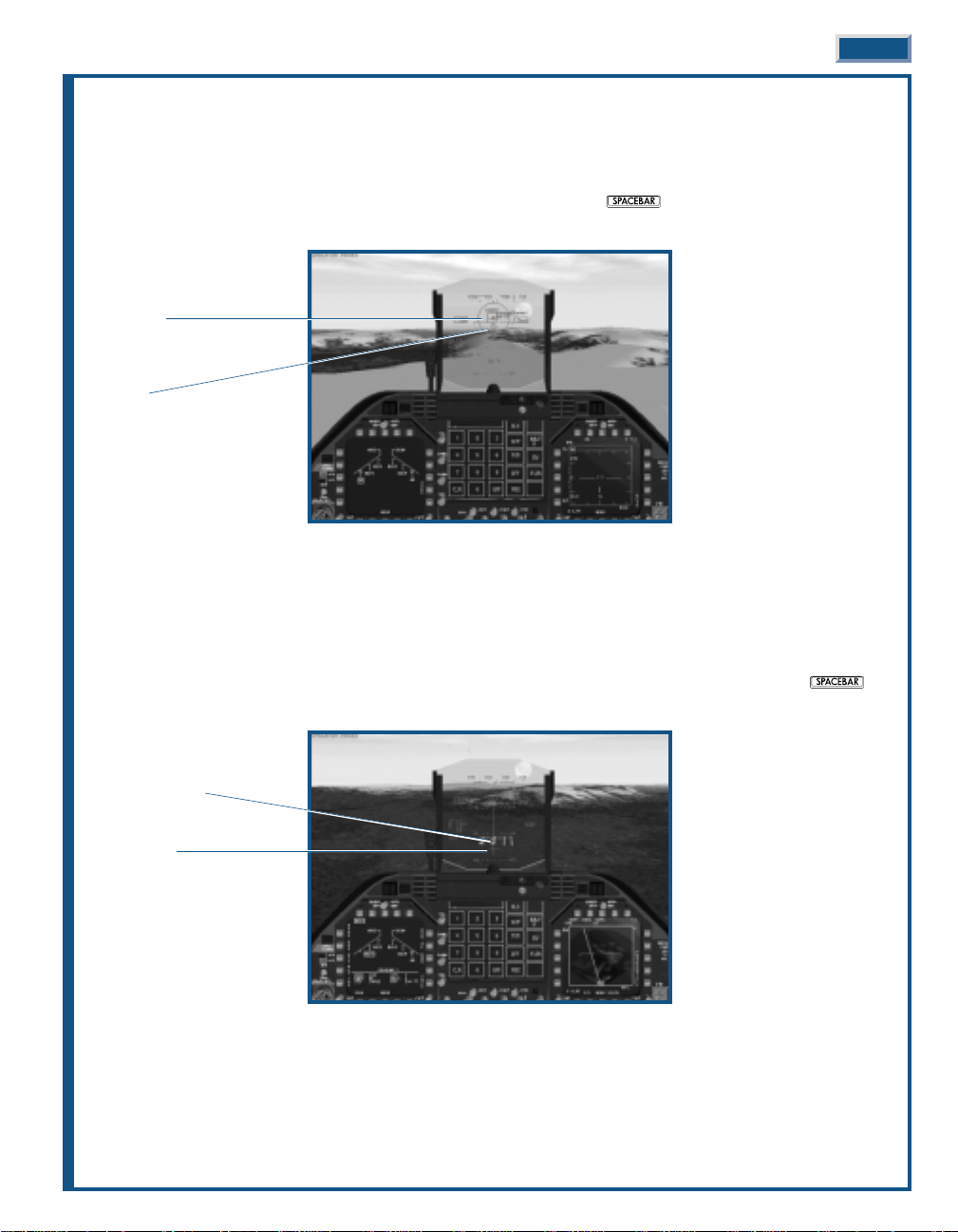
KILLING THE MIG
An unwary MiG is right in front of you; let’s shoot him down.
◆
◆ Press
0
to lock him up on radar.
◆
◆ Once he’s locked press
M
to activate air-to-air attack mode, then press or joystick button 2 to launch
a missile.
BOMBING THE TARGET
Now that that pesky MiG is out of the way, lets put some iron on target by destroying some fuel tanks.
◆
◆ Press
M
to activate air-to-ground bombing mode.
◆
◆ Fly towards the label in front of you marked “Primary Target.”
◆
◆ As you near the target begin a shallow dive and line it up directly to your front. When you get close, the bomb
cross appears at the bottom of the HUD. When the cross is positioned over the Primary Target, press
or joystick button 2 to release a bomb.
FIRST LOOK 1-3
Shoot cue
Target
Bomb cross
Target (fuel tanks)
Page 10
SIGHTSEEING
After you’ve bombed the target, fly around a bit and enjoy the scenery. You can select the various views using the
function keys. Enjoy the game!
1-4 JANE’S F/A-18 FLIGHT MANUAL 1-4
Page 11
IIIINNNNTTTTRRRROOOODDDDUUUUCCCCTTTTIIIIOOOONN
NN
CHAPTER 2
Page 12

CHAPTER 2:
INTRODUCTION. . . . . . . . . . . . . 2-7
The World in the Balance . . . . . . . . . . . . . . 2-7
The Fleet’s Stinger . . . . . . . . . . . . . . . . . . . 2-8
Mailed Fist – The Carrier Battle Group . . 2-10
2-6 JANE’S F/A-18 FLIGHT MANUAL
Page 13
CHAPTER 2:
CHAPTER 2:
INTRODUCTION
INTRODUCTION
“The affairs of war, like the destiny of battles, as well of empires,
hang upon a spider’s thread.” —Napoleon
THE WORLD IN THE BALANCE
With the demise of the Soviet Union in the last decade of the 20THCentury, the traditional ideological rivalry that
had dominated the free world for nearly 50 years has ceased to exist. The cold war mentality of force maximization
and massive defense spending are no longer tenable positions. The United States woke up one day to find itself in
the unenviable position as the last superpower. Victory has its price.
In spite of the dramatic impact stemming from the breakup of the Soviet Union, a period of worldwide peace was
in no way inevitable. The localized and regional conflicts, held in check for many years by the looming
superpowers, were now free to rear their ugly heads. These nationalistic, religious, and ethnic rivalries, while
seemingly non-issues, had in reality continued to churn just below the surface. Once unfettered from their
shackles, they were free to pursue individualistic goals.
For the United States, far reaching economic interests mandate international stability. The time of waging war for
purely political, religious, or geographic gain is no longer good business. In the world of today, the capacity to
capture and maintain regional or global dominance is predominately grounded in economic supremacy. Wars are
astronomically expensive. Conflict is now based more on profit and loss rather than ideological conviction.
While the United States struggles to remain neutral on these
regional issues, the threat of war, while not on a global scale,
remains a real and ultimately an unavoidable consequence of
man’s unquenchable need to possess more and more.
Quick reaction to active or potential hot spots is clearly the
purview of the Navy. The Air Force will certainly argue this point,
but they unquestionably lack the ability to transport their airfields
along with their aircraft. They require forward deployment areas
within the range of the conflict. This necessitates the cooperation
of allied or non-allied nations – never a guarantee. Fixed forward
bases are also much more vulnerable to preemptive or in-conflict
strikes – it is still much harder to hit a moving target.
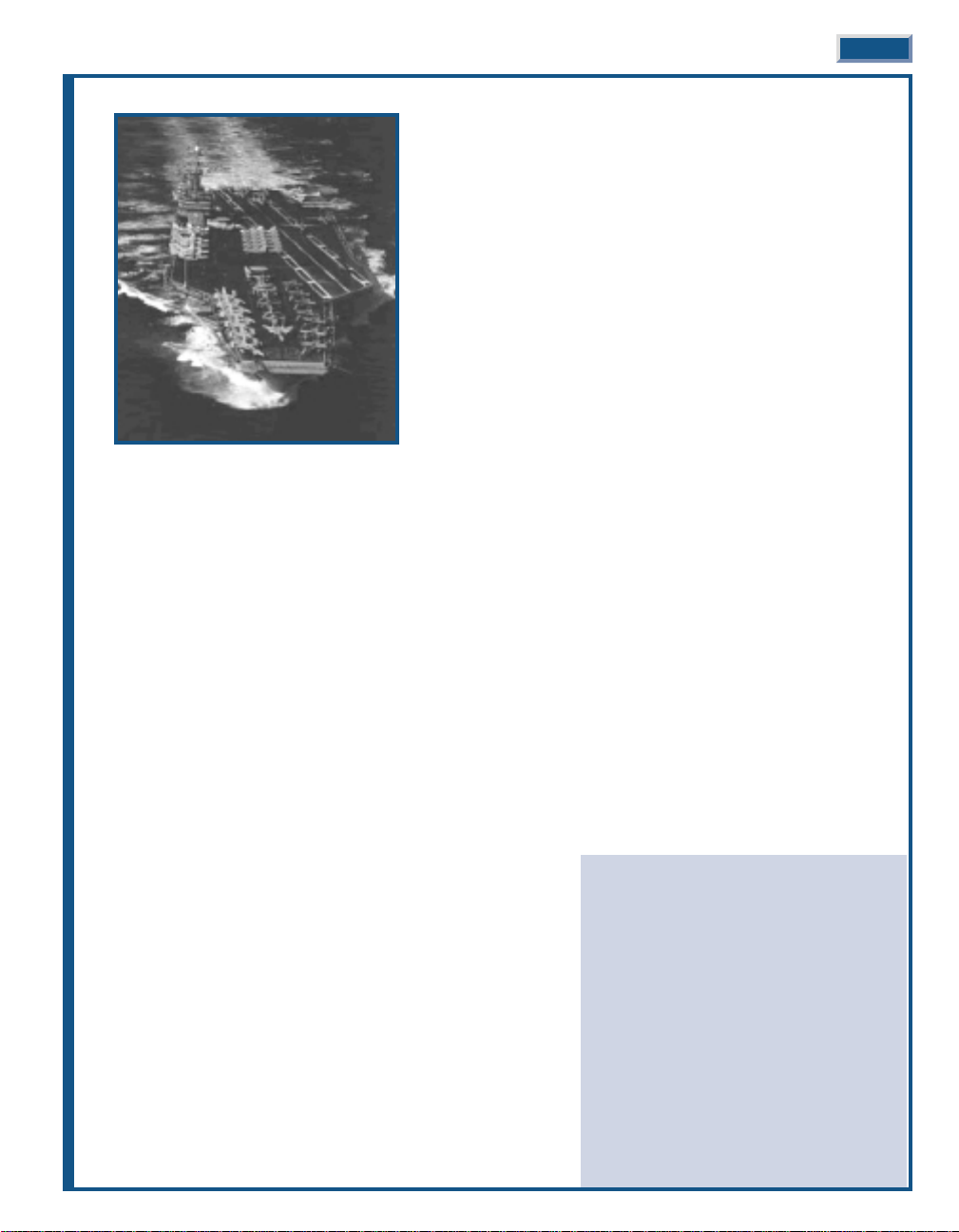
The Navy is the only military arm possessing the wherewithal to quickly project the required force against an
aggressor. Oceans cover nearly three-fourths of the earth’s surface. Those nations having the potential to threaten,
or for that matter act out their aggression, typically occupy or are in close proximity to the coastal regions of the
world. The U.S. Navy’s carrier forces are strategically deployed throughout the world to arrive on station within 48
hours or in rare cases 72 hours. During the 1990 Gulf Crisis, the carriers Eisenhower and Independence were both
on station in range of Iraqi forces within 48 hours.
The vast majority of all products, whether finished goods or raw materials, are transported over water. The nation
with the strongest navy exerts de facto control over the ebb and flow of all these goods. They need not defeat the
opposition forces or for that matter exercise significant military force. Simply blockading ports, thereby preventing the
inflow or outflow of goods, may be sufficient to bring most nations to their knees. Economics ultimately wins out.
It is inevitable the United States will be drawn into shooting wars – these potential conflicts have been
euphemistically dubbed ’Low Intensity Conflicts’ or LICs. The concept of “Global War” is now reserved for conflicts
involving the unthinkable use of nuclear weapons. This does not mean that the fighting or magnitude of
commitment will reflect a minimal or low level of effort on the part of U.S. forces. Given the low current level of
conventional forces, any commitment will require a maximum effort. In any event, the U.S. Navy will undoubtedly
play a major role in any future conflict, LIC or otherwise.
INTRODUCTION 2-7
Page 14
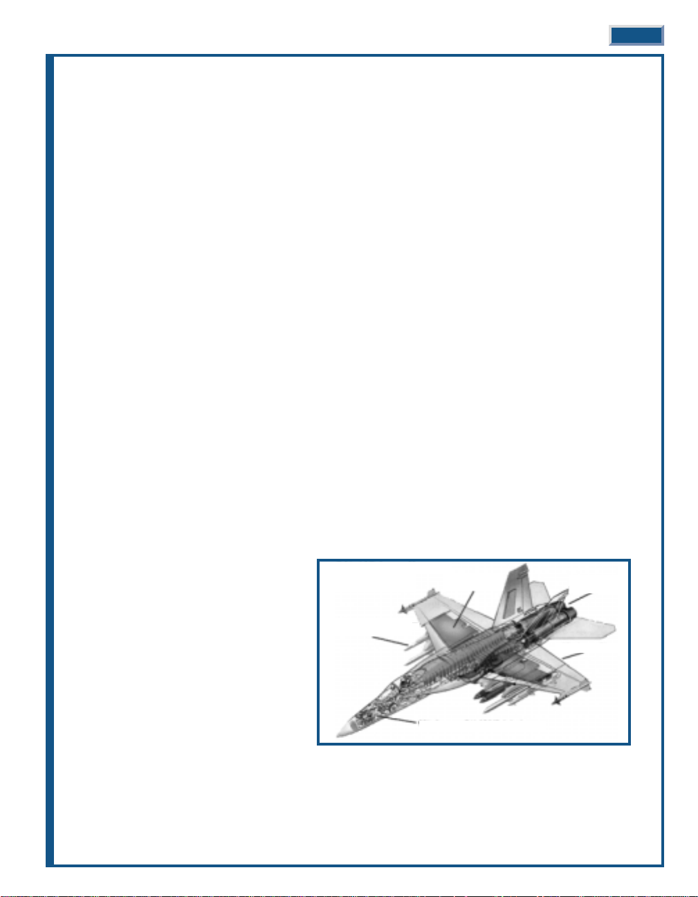
Jane’s F/A-18 models modern naval aviation
at its best, highlighting one of the U.S. Navy’s
most potent weapons – the F/A-18E Super
Hornet. A versatile gem, the single-seat
Hornet-E is equally adept at knocking enemy
aircraft out of the skies as it is in delivering
precision strikes against targets on land or on
the sea. Jane’s F/A-18 does not just stop at
that, it is a highly detailed and stunningly
accurate simulation of naval aviation.
What does all this mean to you? You get see
all from the cockpit of the Navy’s hottest new
multi-role fighter!
THE FLEET’S STINGER
The F/A-18 Hornet was designed to fulfill a number of different roles, hence its F/A (Fighter/Attack) designation.
In the 1970s, the Navy came to the realization that it could no longer afford to develop single-use aircraft. As
conceived, the Hornet was to replace the A-7 Corsair II light-attack and F-4 Phantom air superiority aircraft, at
that time in service with sea-based Navy squadrons and land based Marine squadrons – do not overlook the fact
that the Navy also oversees Marine aviation.
Cost control measures also dictated the method of aircraft selection. Congress and the DOD directed the Navy to
join with the Air Force on its ’lightweight’ fighter program and select a common airframe for both services. Two
competing designs, General Dynamics/Vought’s YF-16 and Northrop/McDonnell Douglas’ YF-17, were in the
running (the ’Y’ designates the aircraft as a prototype). In the past, the Navy and Air Force had worked together in
aircraft concept, design, and development, ostensibly to control acquisition costs – buy a large quantity and the
per unit cost is less. It also streamlines the flow and cost of spare parts.
Well, that is all good in theory. In reality, the Navy and Air Force seldom were of one mind on aircraft selection.
Ironically, the A-7 Corsair II and F-4 Phantom were the most recent examples of inter-service cooperation. These
two aircraft were originally Navy programs “shared” with the Air Force, now the scales were reversed.
A good part of this single-mindedness can be written off to service pride, but the Navy does have some legitimate
arguments. They favor a twin-engine configuration due to the hazards of over-water flight. In addition, carrier
landings, affectionately described as controlled crashes, place extreme stress on the landing gear and
undercarriage. This requires additional structure and weight, reducing the aircraft’s payload – a price the Air Force
is unwilling to pay.
In the end, the Air Force selected the YF-16 and the Navy selected the YF-17. What happened to the single selection
process? General Dynamics/Vought asked the same question. After much lobbying the Navy did prevail and
managed to convince Congress and the DOD to support their decision. The YF-16 became the highly successful F16 Fighting Falcon while the YF-17 evolved into the newly designated F/A-18 Hornet.
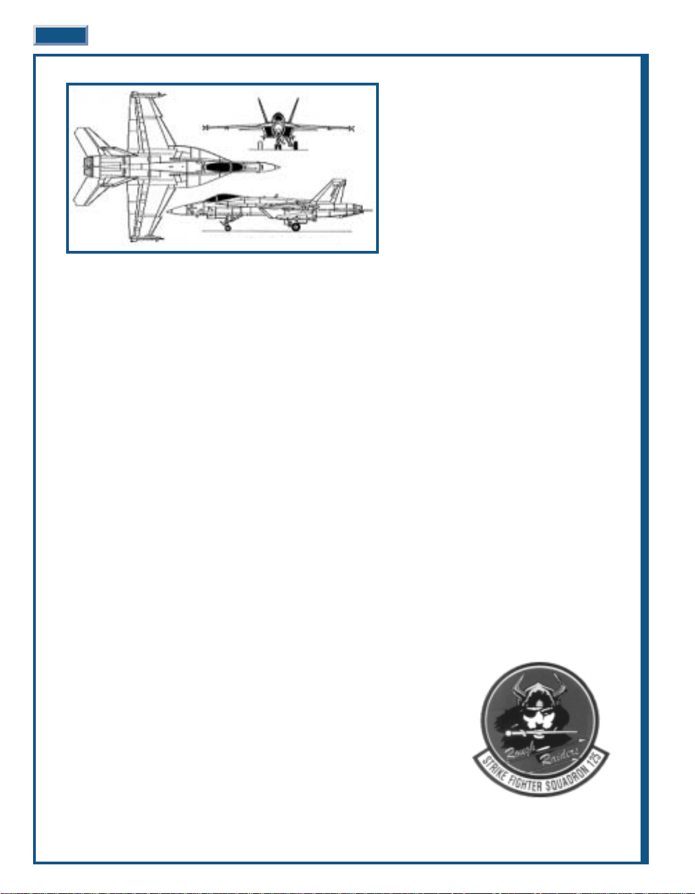
The final F/A-18 Hornet was hardly a YF-17 with a new name stenciled on its nose;
it was essentially an entirely new design. This evolutionary process experienced
its share of pitfalls, but what emerged was a very capable and advanced aircraft.
Although, the production Hornet still had one shortcoming – limited range, or, in
military parlance, “short legs”. After the evaluation signoff, production started in
1978; the first operational aircraft entered service with VFA125, the Rough
Raiders, in 1980.
The Hornet looks a like a smaller version of the F-14 T omcat with its twin-engines
and twin-tails. In spite of its strike role, the Hornet is a dogfighter at heart. Its
nose houses the multi-mode APG-65 radar (APG-73 in late model ’C’ and later
versions) and the 20mm M61 6-barrel Gatling gun. AIM-120 AMRAAM (’C’ and
later) and AIM-7 Sparrow AAMs (or the AAS-38 Nighthawk FLIR/laser targeting
pod) are mounted in two recessed wells on the fuselage; the wingtips are reserved for AIM-9 Sidewinder AAMs.
2-8 JANE’S F/A-18 FLIGHT MANUAL
F/A-18 E Super Hornet
Page 15
The centerline station typically carries an external fuel tank. Its wings have six weapons stations plumbed for
AAMs and a variety of ordnance including Paveway LGBs, AGM-Maverick (IIR version in ’C’ and later), AGM-88
Harm, AGM-84D Harpoon, AGM-84H SLAM, as well as the full series of ’iron’ bombs.
That is enough about the exterior, how about taking a look where the pilot works. The cockpit is a pilot’s dream.
It features a true ’glass’ layout with a series of computer screens replacing the traditional analog gauges. These
displays are extremely versatile, allowing the pilot to configure them to suit a multitude of situations. An advancedgeneration HUD complements the ’head-down’ displays. It can be switched from air-to-air to air-to-ground mode
with a simple flick of a switch on the HOTAS controls. All this high-tech equipment enables the single-seat Hornet
to fulfill the roles previously reserved for two crewmen.
According to naval aviators, a tough audience on a good day, the Hornet is a pleasure to fly. Its FBW flight control
system, the first for a carrier aircraft, makes for extremely responsive fight. Hornet jockeys boast that their bird
can fly the wings off their Air Force counterparts. If that is not enough, the Hornet can even automatically touch
down to a perfect three-wire landing while the pilot sits back and enjoys a day at sea.
After production of 371 F/A-18As, the Hornet continued to evolve and improve with the introduction C/D versions
in 1986 (note that F/A-18 ’Bs’, ’Ds’, and ’Fs’ are the two-seat variants of the A/C/E respectively). With the new C/D
version, the radar, avionics, self-protection systems, engines, and a number of additional systems were also
improved and updated. This was the first of the Hornets to support the AIM-120 AMRAAM AAM and the ImagingInfrared (IIR) version of the AGM-65 Maverick.
The new APG-73 radar markedly improved the Hornet’s air-to-air and air-to-ground signal processing with its fully
programmable digital architecture. In both modes the radar is used to search for targets and then lock onto and track
them for attack. In fact, it was so good that there was never a thought of upgrading it for the new F/A18E Super Hornet.
The C/Ds fixed the shortcomings of the initial A/Bs, with the exception of the fuel issue. Remember that was the
knock against the first model. This was the aircraft envisioned by the Navy planners from the very beginning.
The Marine Corp actually focused its attention on the two-seat ’D’ model. It acquired six squadrons of 72 aircraft
enhanced for night precision strikes to replace the A-6 Intruder in their all-weather attack squadrons. Equipped
above and beyond the normal two-seat Hornets, this improved version was originally dubbed the F/A-18D+.
The rear cockpit can be configured in one of two ways: “missionized” – where it lacks a flight control column, replacing
it with two side-mounted weapon/system stick controllers; or “trainer” – where the it has full flight controls.
The E/F models promise to be the most capable Hornets yet. They were originally proposed in 1991 as a
replacement for the disastrous A-12 Avenger program. The Super Hornet is a major step improvement over the
previous models. This was the opportunity to produce an airframe that would serve well into the 21st Century, and
the designers decided to take this to the max.
The Super Hornet took the basic ’C’ airframe
and stretched it an additional 34 inches. This
resulted in a 25% increase in wing surface as
well as an enlarged horizontal stabilizer – the
tail. This size increase solved what had been
the biggest knock against the Hornet since its
inception – limited internal fuel. The Super
Hornet can carry 33% more fuel for a
whopping 40% increase in range. With the
larger wing, the designers were able to attach
one additional weapon station per wing just
inboard of the wingtips. The Super Hornet
also gets two new powerful F414-GE-400
high-output afterburning turbofans.
Together, the two new engines produce 35% more thrust than the F404s in the C/Ds. However, the new design
retains 90% of the avionics suite from the C/Ds, anchored by the highly capable APG-73 radar.
On the self-protection side, the Super Hornet is the first naval aircraft to employ extensive radar and IR signature
reduction in the form of reshaped engine inlets and radar absorbent coatings. The engine nozzles are designed to
cool the jet exhaust, thereby reducing the aircraft’s infrared signature. The Super Hornet is also the first to carry
the new ALE-50 towed decoy system.
INTRODUCTION 2-9
35% higher
thrust engines
25% larger wing
90% common F/A-18C/D avionics
2 additional multimission
weapon stations
33% additional
internal fuel
F/A-18 E
Super Hornet
Page 16

A proposed version of the ’F’ model is earmarked to replace the four-seat EA-6B Prowler electronic warfare
platform. The two-seat EF-18G ’Electric’ Hornet will probably lead future strike aircraft to their targets, blinding
enemy radar and suppressing enemy air defenses with AGM-88 Harm anti-radiation missiles.
CVW OF TODAY – 2001
14 – F/A-18 Super Hornet Air Superiority & Strike
14 – F-14 Tomcat Fleet Air Defense, Strike & Recon
24 – F/A-18 Hornet Air Superiority & Strike
4 – EA-6B Prowler Electronic Warfare & SEAD
4 – E-2C Hawkeye AEW
6 – S-3B Viking ASW, ELINT & Aerial Refueling
6 – SH-60R Seahawk ASW
2 – CH-60C Seahawk CSAR
74 aircraft
The Hornet is the cornerstone of the Navy’s present and future plans. For a program once under fire from all sides,
it has now emerged as the premier aircraft in the Navy’s arsenal. It currently represents half of the aircraft in every
Carrier Air Wing (CVW). The future holds even more promise for the Hornet and its variants.
As more and more Super Hornets enter service, the venerable F-14 T omcat will retire from service. The Hornet will
then pull double duty as the fleet defense aircraft as well as the primary strike platform. The new Joint Strike
Fighter (JSF), another one of those cooperative Navy and Air Force development programs, will serve as the
medium strike aircraft, though it will also possess a degree of air-to-air capability. The “Electric” Hornet will
replace the EA-6B Prowler while a new design, the Common Support Aircraft (CSA), is scheduled to replace the
versatile E-2 Hawkeye and S3 Viking.
Depending on the outcome of the JSF program, and there is some doubt that it will ever see the light of day, the
Hornet may actually be called upon to fill all offensive and defensive roles.
The Super Hornet first took flight in late 1995. Production commenced in 1998; the first deliveries are expected in
early 2001.
MAILED FIST –
THE CARRIER BATTLE GROUP
As the Navy’s primary conventional weapon, naval surface warfare centers on the carrier battle group (CVBG).
T oday, there are ten active carrier battle groups, each with its assigned CVW. At any one time, any number of these
CVBGs (CV is the military designation for a large conventional take-off and landing carrier) are strategically
deployed throughout the world. As would be expected, its accompanying carrier air wing (CVW) is the primary
offensive and defensive weapon system.
While certainly the most important unit, the carrier is still just one component of the battle group. It is composed
of the carrier, its aircraft, and a number of escorts and support elements. Think of it in terms of trying to sit on a
one or two-legged stool. The aircraft need the carrier, the carrier needs the escorts and support elements, and they
need the carrier and its aircraft. Any one element is ineffective without the others – they are mutually supportive.
The battle group’s CVW is commanded by the “CAG,” short for commander, air group. This individual holds the
rank of Captain, the same as the carrier’s commanding officer. Do not confuse the rank of Captain and the title of
captain. The rank of Captain is a Navy ’four-striper’, equivalent to the rank of Colonel in the Army or Marines. The
title of captain is bestowed upon the individual, regardless of rank, who commands a naval vessel.
The “CAG” and the carrier’s captain work together as peers reporting to the battle group’s commander, a two-star
Rear Admiral. Right about now you are probably wondering why is an air group commander commanding an air
wing. The “CAG” is a traditional title, held in the highest of regard, which has carried over from the time when the
air wing was called an air group. The air group became an air wing in 1975 with the addition of integrated support
and ASW helicopter squadrons.
2-10 JANE’S F/A-18 FLIGHT MANUAL
CVW OF TOMORROW – 2011
36 – F/A-18 Super Hornet Fleet Air Defense & Strike
10 – JSF Air Superiority, Strike & Recon
4 – EF-18G Electric Hornet Electronic Warfare & SEAD
4 – CSA AEW AEW
6 – CSA Sea Control ASW & Recon
2 – CSA ESM ELINT & Aerial Refueling
6 – SH-60R Seahawk ASW
2 – CH-60C Seahawk CSAR
70 aircraft
Page 17
The typical CVW includes about nine squadrons of combat and
support aircraft including the helicopters. Over fifty of the seventyfour aircraft are found in the four F-14 Tomcat and F/A-18 Hornet
squadrons. As the predominate aircraft, the F/A-18 Hornet VFA
(strike fighter) squadrons now outnumber their F-14 Tomcat VF
(fighter) counterparts three to one. The remaining fixed-wing
squadrons consist of the EA-6B Prowler, E-2C Hawkeye, and S-3
Viking squadrons (in both ASW and ELINT roles).
The CVW is no longer just a Navy show. A shortage of aviators
necessitated a change in the once exclusive community. It is now
quite common to find carrier-capable Marine squadrons serving as
one of the F/A-18 Hornet squadrons or as the EA-6B Prowler
squadron.
The third ’leg’ of the battle group is the escorts and support
elements. Here you will find much more diversity than that found
in the composition of the CVW. Vessels are attached and released
from the battle group depending on the immediate situation. For
example, MCM (mine counter-measures) ships could be attached to
a battle group if it is to operate in relatively shallow waters or must traverse a predictable track or narrow channel.
In general, a carrier battle group includes one or two cruisers, two or more destroyers, one or two frigates, one or
two submarines – yes submarines – and a replenishment ship.
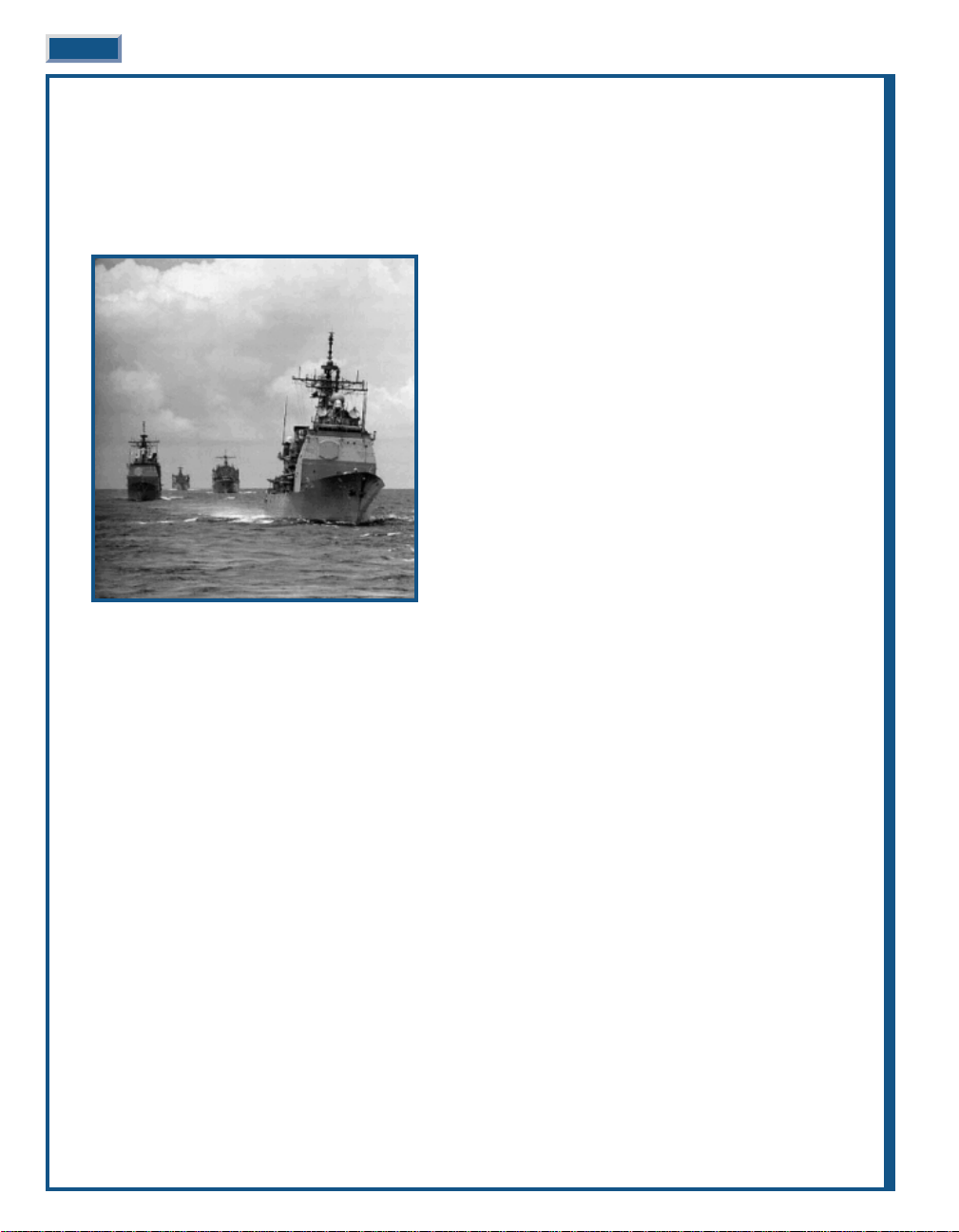
With the retirement of the last remaining nuclear powered-cruiser, the mantel passed to the Ticonderoga class of
Aegis (Greek for shield) guided-missile cruisers (military designation – CG). Even though they possess a
considerable offensive punch with their Tomahawk and Harpoon cruise missiles and two 5-inch guns, the CGs are
there for one purpose – defense. Their highly sophisticated SPY -1 phased-array radar system simultaneously tracks
and engages a multitude of airborne targets. They also automatically control the weapons from the other ships in
the battle group, creating an integrated defensive umbrella. These ships are so effective that the Admiral may elect
to command the battle group from the deck of a Ticonderoga rather than from the traditional spot on the carrier.
The destroyer element draws its force from the old and the new. The new takes form in the Arleigh Burke class of
guided-missile destroyers (military designation – DDG). In fact, the Burkes are the newest class of combat ships in
the Navy’s arsenal. These well-designed ships also utilize the Aegis system with its SPY-1 radar. Though they are
similar in capability to the Ticonderoga class, the Burkes carry fewer missiles and a single 5-inch gun.
The other destroyer option is drawn from the older Spruance class (military designation – DD). These ships were
designed at the height of the cold war for anti-submarine (ASW) operations. As the Soviet deep-water submarine
threat waned, their offensive punch was enhanced with the addition of Tomahawk cruise missiles to complement
their Harpoons and two 5-inch guns.
The frigates are from the Oliver Hazard Perry class of guided-missile
frigates (military designation – FFG). Even though these frigates
hauled down their sails a long time ago, they are more than able to
fulfill a number of important roles. Their size disguises very capable
offensive and defensive capabilities. With a limited number of
Harpoons and a single 3inch gun, they are best suited for escort duty
and shallow water operations. Nevertheless, frigates are the most
common class of warships in service today with the world’s navies.
The last combat support element is the submarine. Now what are
submarines doing in a surface battle group? They serve a very
important role in keeping with their unique abilities. Their far
ranging and stealth abilities make them well suited for maritime
reconnaissance and strike missions. More importantly, they are the
battle group’s most potent anti-submarine weapon, since the best
defense against a submarine is another submarine. While the
surface escorts maintain relatively close contact with the carrier,
the subs range far ahead and abeam of the battle group. The
INTRODUCTION 2-11
SIZE DOES MATTER
During World War I and II displacement,
armor and gun size were used to classify
warships. The four primary classes of
modern warships are loosely grouped
by length since displacement is no
longer a direct indication of combat
strength and guns have given way to
missiles as the primary armament.
Modern cruisers are 150m or longer.
Destroyers are 95 to 140m long. Frigates
are similar to destroyers in length but
are more lightly armed. Corvettes are 60
to 100m in length.
Page 18
Improved Los Angeles class, the 688Is, are the most modern boats available (military designation – SSN, note that
subs are call boats). They are also able to launch Tomahawk cruise missiles from their vertical launch system and
Harpoons from their torpedo tubes.
Lastly, the battle group is supported by at least one fast combat support ship. While the carrier and subs do not
require fuel, the remainder of the battle group needs oil for propulsion, and in any event, everyone needs to eat.
The Wichita and Sacramento classes (military designation – AO) are floating shopping centers. These ships triple
their basic displacement with loads of fuel oil, aviation gas,
food, spare parts, general supplies and ammunition. The only
ship larger is the carrier.
Together, the battle group is much stronger than the
capabilities of the individual vessels – a perfect example of
the sum being greater than its parts. However, the whole
carrier concept has been under extreme pressure due to its
high price tag. A battle group costs nearly $20 billion to build
and equip, and another $1 billion annually to operate. So
expensive, few countries can afford to build or even operate
such a costly weapon system.
The advent of cruise missile has applied additional pressure.
The critics compare the $1 million price tag for a Tomahawk
cruise missile with the $58 million for a single F/A-18E Super
Hornet, and the dollars are just one part of the argument. On
an even more important note, the unmanned T omahawk does
not place a pilot’s life in danger.
Though, cruise missiles are great at hitting fixed points, they
are limited in hitting moving targets, especially ships at sea.
An aircraft’s pilot is also able to evaluate a situation before
dropping the bombs; the cruise missile obediently and blindly attacks its target. Even more notable, a CVW can
deliver about 450 tons of ordnance in a day – the equivalent of 900 Tomahawks!
Today, the carrier and its air wing are the most mobile and flexible striking force in the United States arsenal.
Whether called upon to carry the action to the enemy or hold one at bay, its ability to project military presence
makes it the ultimate weapon system.
2-12 JANE’S F/A-18 FLIGHT MANUAL
Page 19
IIIINNNNTTTTEEEERRRRFFFFAAAACCCCEEEE OOOOVVVVEEEERRRRVVVVIIIIEEEEWW
WW
CHAPTER 3
Page 20

CHAPTER 3:
INTERFACE OVERVIEW . . . . . . 3-15
General Instructions . . . . . . . . . . . . . . . . . 3-15
Pop-Up Windows . . . . . . . . . . . . . . . . . . . . . . 3-15
Main Menu . . . . . . . . . . . . . . . . . . . . . . . . 3-16
Training. . . . . . . . . . . . . . . . . . . . . . . . . . . 3-16
Loading a Training Mission. . . . . . . . . . . . . . 3-17
Training Main Briefing. . . . . . . . . . . . . . . . . . 3-17
Instant Action . . . . . . . . . . . . . . . . . . . . . . 3-17
Fly Mission. . . . . . . . . . . . . . . . . . . . . . . . . . . 3-18
Instant Action Options . . . . . . . . . . . . . . . . . . 3-19
Friendly Parameters. . . . . . . . . . . . . . . . . . . . 3-19
Enemy Parameters. . . . . . . . . . . . . . . . . . . . . 3-20
Environment . . . . . . . . . . . . . . . . . . . . . . . . . 3-20
Instant Action Debriefing . . . . . . . . . . . . . . . . 3-20
Single Mission. . . . . . . . . . . . . . . . . . . . . . 3-21
Loading a Mission . . . . . . . . . . . . . . . . . . . . . 3-21
Main Briefing. . . . . . . . . . . . . . . . . . . . . . . . . 3-22
Airframe/Pilot Selection . . . . . . . . . . . . . . . . . 3-25
Pilot Edit . . . . . . . . . . . . . . . . . . . . . . . . . . . . 3-26
Squadron Edit . . . . . . . . . . . . . . . . . . . . . . . . 3-26
Arming . . . . . . . . . . . . . . . . . . . . . . . . . . . . . . 3-27
Custom Arming . . . . . . . . . . . . . . . . . . . . . . . 3-28
Fly Mission. . . . . . . . . . . . . . . . . . . . . . . . . . . 3-29
Debriefing . . . . . . . . . . . . . . . . . . . . . . . . . 3-29
Detailed Kill Summary . . . . . . . . . . . . . . . . . 3-29
Detailed Debrief. . . . . . . . . . . . . . . . . . . . . . . 3-30
Weapon Stats. . . . . . . . . . . . . . . . . . . . . . . . . 3-31
Pilot Status. . . . . . . . . . . . . . . . . . . . . . . . . . . 3-31
Mission Playback . . . . . . . . . . . . . . . . . . . . . . 3-32
Summary . . . . . . . . . . . . . . . . . . . . . . . . . . . . 3-32
Time Log . . . . . . . . . . . . . . . . . . . . . . . . . . . . 3-33
Detailed Time Log . . . . . . . . . . . . . . . . . . . . . 3-33
Campaign . . . . . . . . . . . . . . . . . . . . . . . . . 3-33
Select Campaign . . . . . . . . . . . . . . . . . . . . . . 3-33
Select Squadron. . . . . . . . . . . . . . . . . . . . . . . 3-33
Campaign Introduction . . . . . . . . . . . . . . . . . 3-34
Airframe/Pilot Selection . . . . . . . . . . . . . . . . . 3-34
Fly Mission. . . . . . . . . . . . . . . . . . . . . . . . . . . 3-34
Multiplayer . . . . . . . . . . . . . . . . . . . . . . . . 3-35
Direct Serial (Null Modem) . . . . . . . . . . . . . . 3-36
Modem. . . . . . . . . . . . . . . . . . . . . . . . . . . . . . 3-37
IPX/SPX Network . . . . . . . . . . . . . . . . . . . . . 3-37
TCP/IP Network . . . . . . . . . . . . . . . . . . . . . . . 3-38
Chatting With Other Players . . . . . . . . . . . . . 3-39
Who’s the Host?. . . . . . . . . . . . . . . . . . . . . . . 3-39
Hosting a Mission . . . . . . . . . . . . . . . . . . . . . 3-41
Disconnect Player . . . . . . . . . . . . . . . . . . . . . 3-41
Joining a Mission. . . . . . . . . . . . . . . . . . . . . . 3-41
Tools . . . . . . . . . . . . . . . . . . . . . . . . . . . . . 3-43
Mission Builder . . . . . . . . . . . . . . . . . . . . . . . 3-43
Squadron/Pilot Edit . . . . . . . . . . . . . . . . . . . . 3-43
Jane’s Reference. . . . . . . . . . . . . . . . . . . . . . . 3-43
3-14 JANE’S F/A-18 FLIGHT MANUAL
Page 21
CHAPTER 3:
CHAPTER 3:
INTERF
INTERF
ACE OVER
ACE OVER
VIEW
VIEW
Starting the game. After completing the installation, double-left click on the Jane’s F/A-18 shortcut icon on your
desktop, or select Programs/Jane’s Combat Simulations/F/A-18 from the Windows START menu.
You can bypass the Introduction by pressing
s
.
GENERAL INSTRUCTIONS
Jane’s F/A-18 utilizes a cursor-driven, mouse controlled interface. Unless otherwise
indicated, “click” refers to a single left-click of the mouse on an option.
In the lower-right corner of nearly every screen, except the MAIN menu, is a circle divided into four distinct
controls – three around the other edge and one smack in the middle. They include a right pointing FORWARD
control, a left pointing BACK control, a HELP question mark control, and a rotating “artificial horizon” in the
middle.
Think of FORWARD and BACK as if they were web controls: FORWARD moves you to the next screen in the
sequence and BACK returns to where you just came from. Note on some screens the FORWARD control is “grayedout,” as there is no next screen.
HELP displays a window with information pertinent to the current screen.
In most cases, clicking on the artificial horizon displays an OPTIONS screen.
The screen may also include one or more small circular controls along the bottom.
POP-UP WINDOWS
Often, pop-up windows appear. Selections are made and information entered from these windows.
OK saves any selections or changes you’ve made in the window and returns you to the original screen.
CANCEL returns you to the original screen without saving any of the changes you made.
INTERFACE OVERVIEW 3-15
Page 22
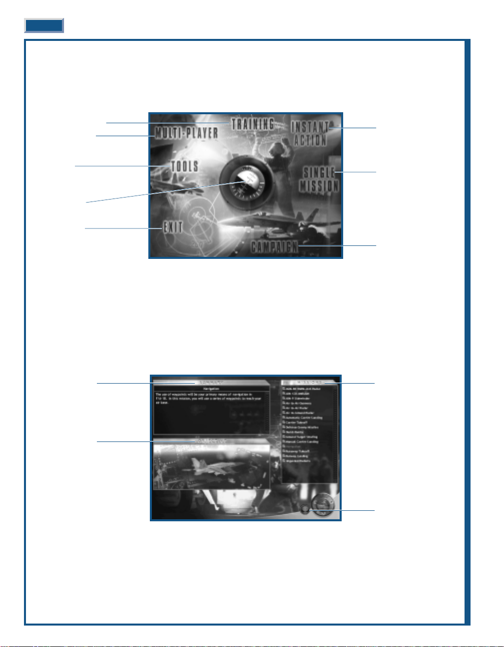
MAIN MENU
The first thing you see after the introductory video is the MAIN menu screen. It’s divided into eight areas
controlling one or more functions and a centrally located artificial horizon. You select a control by moving the
cursor into its area to highlight it, and click.
Notice that it is not necessary to click on the control word – click anywhere in the highlighted area to proceed.
First-time Hornet pilots begin playing using novice settings. Gameplay options can be set in the OPTIONS (the artificial
horizon) menu.
TRAINING
Jane’s F/A-18 includes a variety of training missions covering the basics of flying this sophisticated fighter from
takeoff, through combat, to landing on the deck of a carrier.
It’ll be well worth you taking some time to fly at least the first few training missions. If you’re unfamiliar with
carrier operations, the take-off and landing procedures are quite different from land-based operations.
3-16 JANE’S F/A-18 FLIGHT MANUAL
Fly a Training Mission
Multiplayer Setup
The Tools
(Mission Builder, Pilot/Squadron
Edit, and Jane’s Reference)
Game Options
Exit the Game
Mission Summary
Mission Objective
Available Missions
Chat Control
(Multiplayer Only)
Fly an Instant Mission
Fly a Single Mission
Fly in a Campaign
Page 23
LOADING A TRAINING MISSION
The MISSIONS list is a scrollable window on the right side of the screen.
◆
◆ Click on the mission name (listed in Missions window) to display a summary of the mission.
◆
◆ Double-click on the mission name to immediately display the mission briefing.
◆
◆ Or click FORWARD to display the mission briefing.
Notice that where you would expect to see the normal FORWARD indicator, a small aircraft is substituted – this is the
Fly Mission control. When you are satisfied with all elements, you’re ready to jump in the pilot’s seat and takeoff.
◆
◆ After the briefing displays, click FLY to begin the mission.
◆
◆ Or after the briefing displays, click BACK to return to the initial TRAINING menu.
Mission Summary: The upper-left window displays a high-level summary of the mission. Read this information to
determine if this is the mission for you.
Mission Objective: The lower-left window displays a picture of the mission objective.
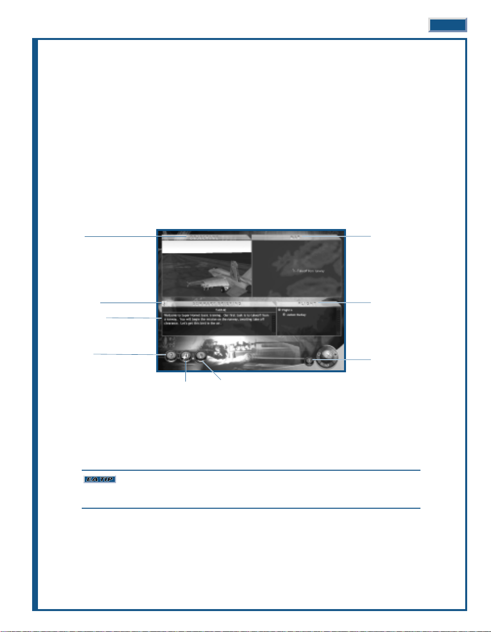
TRAINING MAIN BRIEFING
For more details on the Main Briefing, see Single Mission: Main Briefing, p. 3-22
INSTANT ACTION
If you’re looking to quickly select a mission and get in there and mix it up with the enemy, Instant Action is just
the ticket. The computer creates a stand-alone mission from the parameters you select. You determine the
complexity – playing a simple one-on-one, or skew the odds either way. It’s all up to you.
Instant Action is not intended as a replacement for honest to goodness training. If you’re
unsure how to handle the F/A-18E Super Hornet, spend some time with the training missions before
strapping into the Super Hornet.
INTERFACE OVERVIEW 3-17
Objective
Voice Summary
Summary Briefing
Mission Map
Arming Airframe/Pilot
Mission Map
Flights/Pilots
Chat Control
(Multiplayer Only)
Page 24
FLY MISSION
Click FLY to begin the mission.
Number of Wingmen: You can go it alone or select up to seven wingmen. Wingmen duplicate your weapon
package.
A/G Target: Determines the type of ground targets you must destroy, if any – you may select none for an air-
to-air mission.
Enemy Aircraft: Select the type of enemy aircraft. Y ou can select from any aircraft available in the game – from
lumbering 707s to hot MiG-29s. All enemy pilots fly the same aircraft.
Number of Enemy: The default is two, but you can select as many as eight.
Position: You determine the advantage, if any, of your starting location.
◆
◆ “Neutral” means the enemy starts at the same distance from the waypoint as you and at approximately the
same speed.
◆
◆ “Advantage” means you begin the mission on the tail of the enemy.
◆
◆ “Disadvantage” means that you are positioned ahead of the enemy. The enemy will have the advantage of seeing
you first.
Time of Day: Choose the starting time of day for the mission.
3-18 JANE’S F/A-18 FLIGHT MANUAL
Instant Action Options
Number of Wingmen
Target Position
Enemy Aircraft
Number of Enemy
Time of Day
Page 25
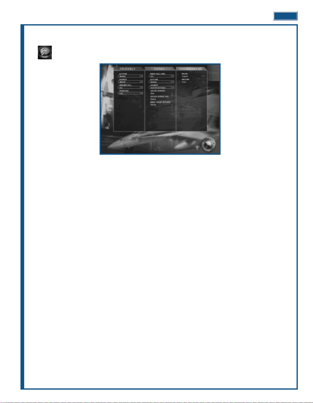
INSTANT ACTION OPTIONS
The Instant Action Options expand on the basic settings. You are not required use to these options.
Set any or all parameters in Friendly (your aircraft and wingmen), Enemy (the bad guys), and Environment (clear
for miles or pea soup).
◆
◆ Click on a parameter to display available options. Some parameters are inactivated due to previous selections.
For example, if you select zero wingmen, the formation parameter is not too useful.
◆
◆ Click on an option within the parameter.
FRIENDLY PARAMETERS
Altitude: Choose to start the mission altitude at low, medium, high or at a random selection from the three options.
The F/A-18E is very comfortable at low altitude, but if you aren’t familiar with the avionics and are flying in the
mountains, start the mission at medium or high altitude, just to be safe.
Loadout: Select your weapon loadout from the available options.
Wingmen Skill: This parameter determines the skill level of your wingmen. A Rookie pilot is more likely to make a
mistake that could place the mission in jeopardy; whereas an Expert or random pilot is more likely to deliver in a pinch.
Formation: Select the formation for you and your wingmen.
◆
◆ “Wedge” is a V-shape, except two aircraft (you and a wingman) share the lead position.
◆
◆ “Line” positions all your wingmen parallel to one side of you, perpendicular to the waypoint path.
◆
◆ “Trail” positions your wingmen in a line directly behind you.
◆
◆ “V” is V-shaped, with you at the front.
◆
◆ “Box” positions you and your wingmen in a rectangular-shaped formation at different altitudes.
◆
◆ “Wall” positions you and your wingmen similar to a “Line” but at different altitudes.
INTERFACE OVERVIEW 3-19
Page 26
ENEMY PARAMETERS
Enemy Skill Level: Select the skill level of the enemy pilots. The less skilled they are, the fewer offensive/defensive
maneuvers they’re capable of performing. If they’re flying 707s, you may want to give them a break and assign ace pilots.
Altitude: Set the enemy aircraft’s altitude at low, medium, high or at a random selection from one of the three
options. Keep one thing in mind: if you assigned a less maneuverable aircraft to the enemy (our old friend the 707),
you may want to start them at medium altitude.
Loadout: Since the enemy can be flying any type of aircraft, “Loadout” only determines what type of ordnance the
enemy aircraft is carrying, not the exact weapons. You may also select random as the option.
◆
◆ “Empty” is naked, no weapons, only chaff and flares – not very sporting of you.
◆
◆ “Guns Only” is only a full load of gun ammo – assuming the aircraft has a gun.
◆
◆ “IR Only” indicates more sensitive heat-seeking missiles that track their targets regardless of the direction of
launch.
◆
◆ “SARH Only” indicates a missile with radar guidance requiring constant illumination from the firing aircraft.
◆
◆ “Active Only” indicates a fully active “fire-and-forget” missile – long ranged and very dangerous.
◆
◆ "Mixed Anti-Air" indicates a balanced loadout of guns, IR, and radar-seeking weapons providing the enemy
aircraft can carry those weapon types.
Ground Defenses: Determines the “density” of the ground defenses along your waypoint path and around the ground
target.
Ground Defenst Skill: Sets the skill level of the enemy ground defenses.
Enemy Target Distance: Determines the flight distance to the enemy targets.
ENVIRONMENT
Region: Choose the type of terrain for the mission setting.
Weather: Choose the weather for the mission. The F/A-18E is equally adept at flying under any conditions, but it’s
easier to fly in clear weather.
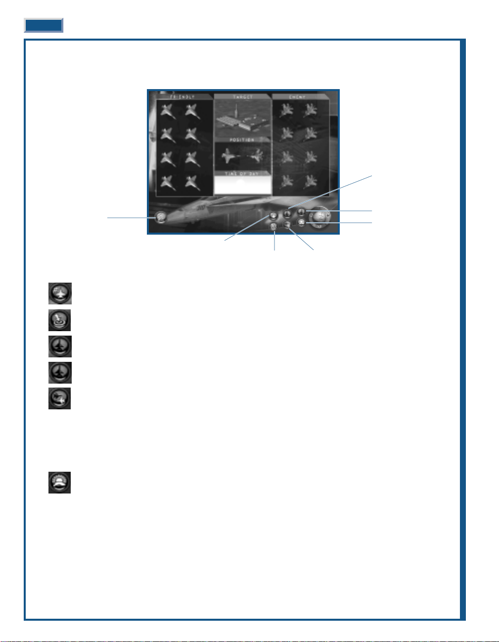
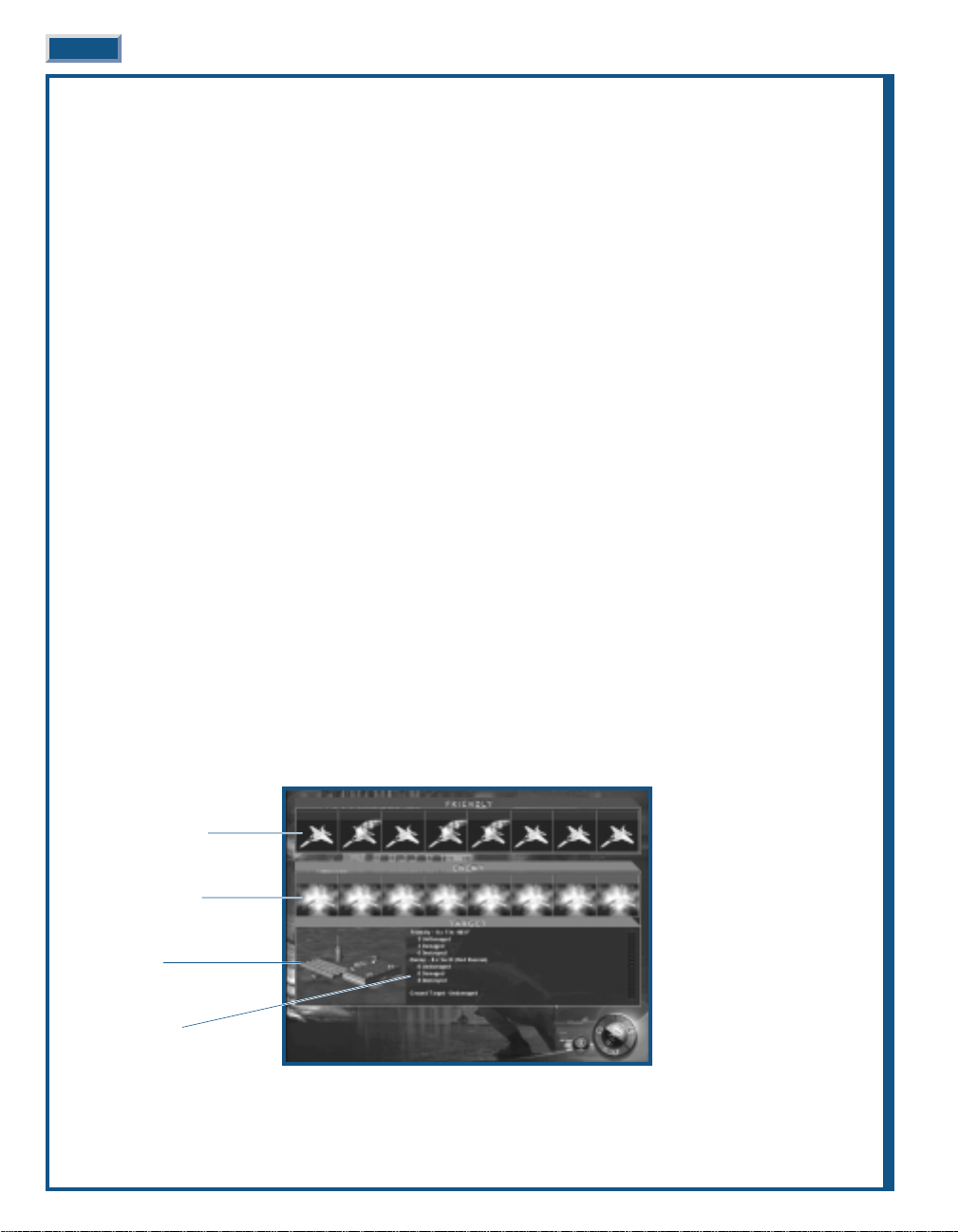
INSTANT ACTION DEBRIEFING
At the conclusion of each Instant Action mission, the Debriefing screen displays. It provides visual feedback on
how well you did against the enemy aircraft and the status of the ground target, if any. A text summary also
describes the mission results.
3-20 JANE’S F/A-18 FLIGHT MANUAL
Friendly Aircraft Status
Enemy Aircraft Status
Ground Target
Mission Summary
Page 27
Friendly Aircraft Status: Visually displays the status of your aircraft and up to seven-wingmen. Damaged aircraft trail
smoke while an explosion covers destroyed aircraft.
Enemy Aircraft Status: Visually displays the status of up to eight enemy aircraft. Damaged aircraft trail smoke while
an explosion covers destroyed aircraft.
Ground Target Status: If a ground target was included in the mission, it appears as destroyed or undamaged
depending on its status.
Mission Summary: A text summary describes the status of the friendly and enemy aircraft and the ground target.
◆
◆ Click FORWARD to return to the Menu screen.
SINGLE MISSION
Single missions are just that, missions with a very singular purpose. Here, you can focus just on the tasks at hand
without worrying about the future – that comes later in the campaign. Just keep one thing in mind, these missions
are not intended as training. You’d best be on your toes once the mission starts – the unrelenting action is nothing
short of fast and furious.
Any mission created in the MISSION BUILDER and saved to the MISSION subdirectory of the
game, appears in the list of available missions. Note that missions still under construction also appear in
the mission list. Selecting missions under construction is a good way of determining how well they
work.
LOADING A MISSION
The MISSIONS list is a scrollable window on the right side of the screen. The list of missions includes both preexisting missions and those created in the MISSION BUILDER.
◆
◆ Click on the mission name (listed in Missions window) to display a summary of the mission.
◆
◆ Double-click on the mission name to immediately display the mission briefing.
◆
◆ Or click FORWARD to display the mission briefing.
◆
◆ After the briefing displays, click FORWARD to begin the mission.
◆
◆ Or after the briefing displays, click BACK to return to the initial SINGLE MISSION menu.
Mission Summary: The upper-left window displays a high-level summary of the mission. Read this information to
determine if this is the mission for you.
Mission Objective: The lower-left window displays a picture of the mission objective.
INTERFACE OVERVIEW 3-21
Mission Summary
Mission Objective
Chat Control (Multiplayer Only)
Available Missions
Page 28
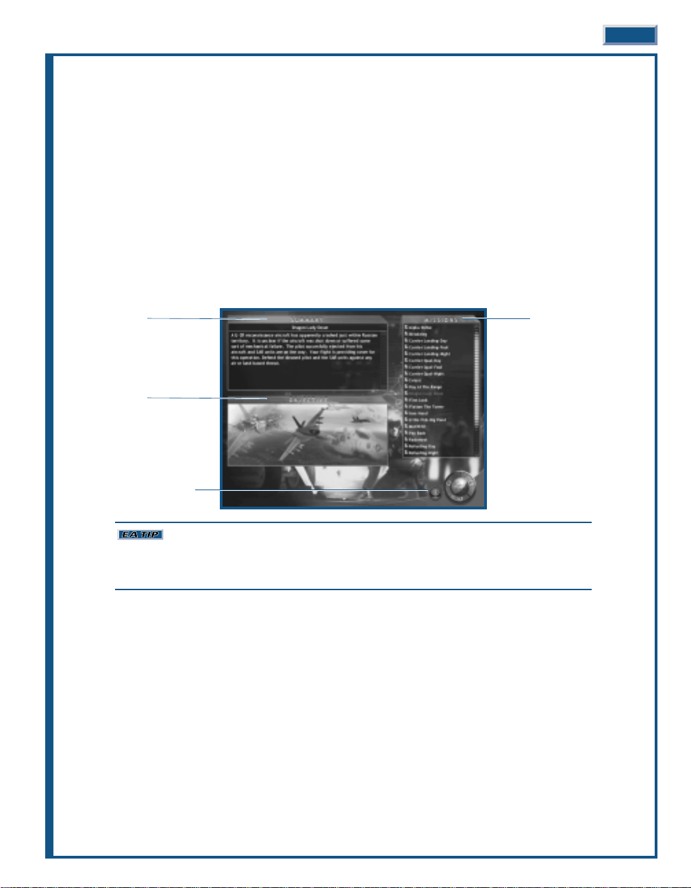
MAIN BRIEFING
The Briefing screen is where you can fine-tune any or all of the mission parameters or if you prefer, just start the
mission. Click FORWARD to start the mission at any time. All of the available mission information can be
reviewed, the mission map adjusted, and the mission’s aircraft and pilots can be adjusted or even replaced.
Objective(s): The upper-left window displays a picture of the mission objective.
Map: The upper-right window displays a map of the mission area.
Summary Briefing: The lower-left window displays a summary of the mission’s briefing.
Flight: The lower right window displays a picture of the mission’s flights and assigned pilots.
Voice Summary: Missions can have voice support describing the objectives and briefing. If available, click the speaker
to play or stop play.
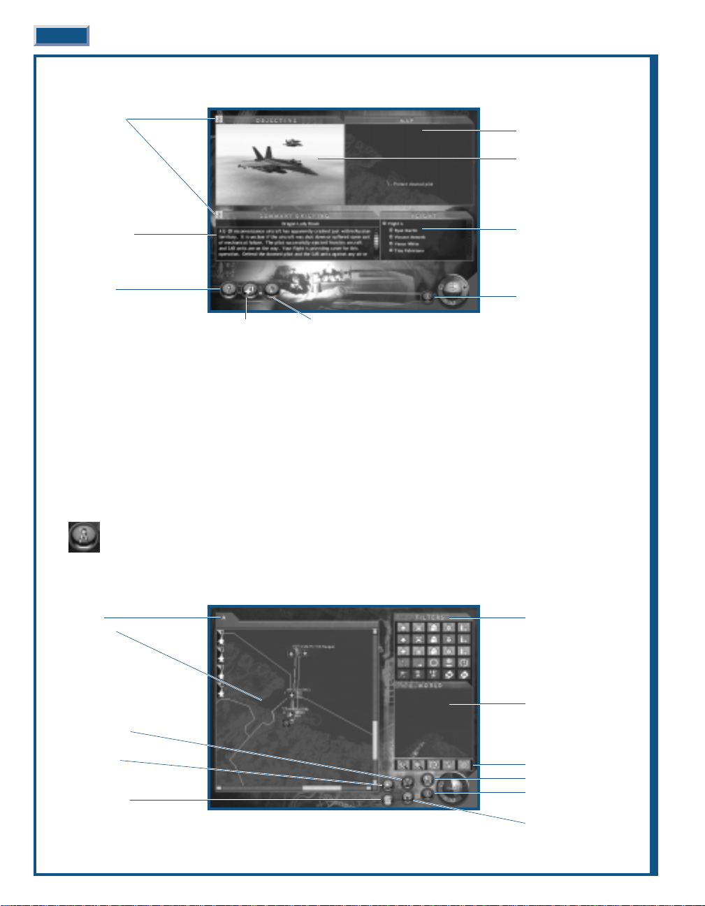
MISSION MAP
All currently known situational awareness is graphically viewed from the Mission Map. This includes the
locations of waypoints for each flight, the Mission’s Bullseye, JSTARS and FACs aircraft, and any known
threats. You may also move, add or delete waypoints from the Mission Map.
From this screen you can also move to a detailed description of the briefing, review available intelligence
information or modify the target designations.
3-22 JANE’S F/A-18 FLIGHT MANUAL
Flight Tab
Mission Map
Delete Waypoint
Add Waypoint
Detailed Briefing
Map Filters
World
Map Controls
Targeting
Chat Control
(Multiplayer Only)
Intelligence
Voice Summary
Summary Briefing
Mission Map
Airframe/Pilot Arming
Mission Map
Objective
Flights/Pilots
Chat Control
(Multiplayer Only)
Page 29

MAP FILTERS
The upper-right window contains five rows of icons that control the information displayed on the Mission Map. Colors
are utilized to designate ownership: green – friendly, red – enemy, gray – neutral, and blue – information. Toggle an
icon to turn the item type on/off. Take time to experiment with the different map filters observing each one’s effect.
MAP CONTROLS
The middle-right window contains a single row of five green icons that control the scale and position of the Mission Map.
Revert: Clicking REVERT returns the Mission Map to its original view.
Zoom Area: Click ZOOM AREA to select an area to view.
◆
◆ Click-and-drag an area on the Mission Map. A red box outlines as you click-and-drag.
◆
◆ Release the mouse button and click again. The area described now fills the Mission Map window.
Center on Cursor: Click CENTER ON CURSOR to position the Mission Map.
◆
◆ Click a location on the Mission Map. The Mission Map display centers on that point.
The mission map enables you to not only view mission related information but to also move, add or delete
waypoints for any friendly aircraft.
ADD WAYPOINT
◆
◆ Click ADD WAYPOINT (You move an existing waypoint by clicking-and-dragging it to a new location). You
must click ADD WAYPOINT for each new waypoint.
◆
◆ Click on the waypoint just before the waypoint you want to add. If you want to add a waypoint prior to
Waypoint 1, click on the aircraft itself.
◆
◆ Click on the location of the new waypoint
INTERFACE OVERVIEW 3-23
Aircraft
AAA Site
SAM Site
Waypoint Path
Airbases
Weapons Ranges
Ground Radar
Radar Ranges
Mission Label
Waypoint Range Waypoint Time World Label
Ground Units Structures Naval Units
Zoom In Center on Cursor
Zoom Out Revert Zoom Cursor
Page 30
3-24 JANE’S F/A-18 FLIGHT MANUAL
DELETE WAYPOINT
◆
◆ Click DELETE WAYPOINT. You must click DELETE WAYPOINT for each deletion.
◆
◆ Click on the waypoint to delete.
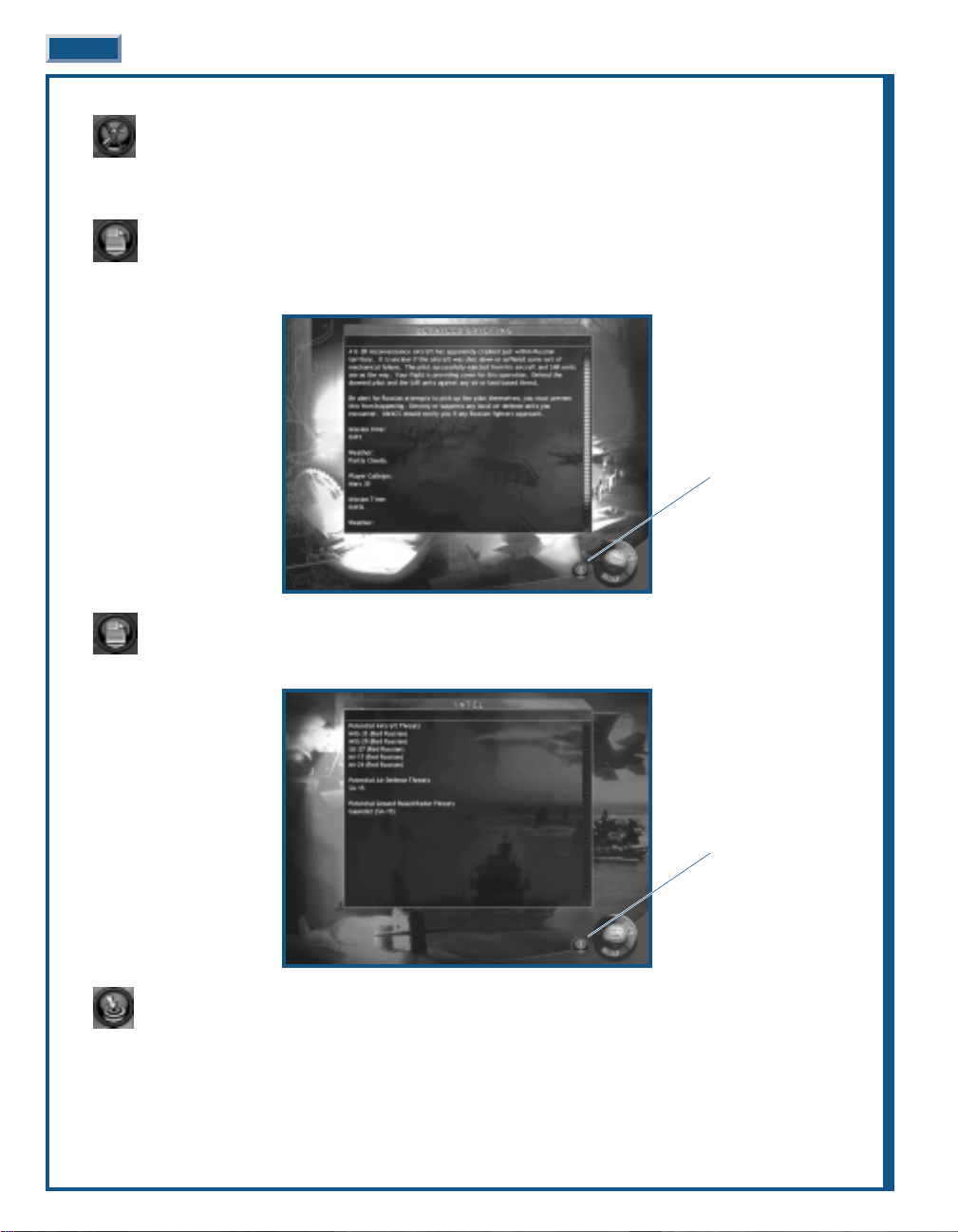
DETAILED BRIEFING
◆
◆ Click DETAILED BRIEFING to view an expanded description of the mission. Clicking BACK returns to the
Main Briefing.
INTELLIGENCE
◆
◆ Click INTELLIGENCE to view the most current intel data relating to the mission.
TARGETING
◆
◆ Click TARGETING to modify the target selection.
Chat Control
(Multiplayer Only)
Chat Control
(Multiplayer Only)
Page 31

When a mission has a ground target, TARGETING is enabled on the Mission Briefing Screen. Your pilots are
assigned certain targets – one target per waypoint per pilot. You may adjust these assignments as desired.
Assign Target
◆
◆ Click Assign Target.
◆
◆ Click the desired wingman number.
◆
◆ Click the target’s icon (if aircraft) or white dot (if other object).
Delete Target Assignment
◆
◆ Click DELETE TARGET and click the target in the Target List.
AIRFRAME/PILOT SELECTION
You can accept assigned pilots, move them into different slots or replace pilots from the roster. You are
always in the aircraft with the identification number ending in “1” of “A” Flight.
◆
◆ Assign a pilot by click-and-dragging a name from the Roster (grayed-out pilots are unavailable) to an empty
slot in the Assigned Pilots’ Window.
◆
◆ Replace a pilot by click-and-dragging another pilot to an occupied slot. The original pilot is returned to the
Roster.
◆
◆ Swap assigned pilot positions by click-and-dragging a pilot into another pilot’s slot.
◆
◆ Remove a pilot by click-and-dragging a pilot off the Assigned Pilots’ Window.
INTERFACE OVERVIEW 3-25
Assigned Pilots
Aircraft Information
(Campaign Only)
Pilot Information
(Campaign Only)
Squadron Exit
Pilot Exit
Available Pilots
Chat Control
(Multiplayer Only)
Flight Tab
Mission Map
Assign Target
Delete Target
Target List
Map Controls
Chat Control
(Multiplayer Only)
Page 32

PILOT EDIT
Through the PILOT EDIT, you acquire in-depth information about any pilot listed in the Roster. You are
also able to create new pilots, edit existing pilots or delete pilots. Pilot Edit is also available from under
the TOOLS Menu.
The Pilot Info window lists the information about the pilot highlighted in red on the Pilot’s window. The pilot’s
name, rank, and summary statistics for single missions and for the campaign are listed adjacent to the pilot photo.
Click on a pilot in the Pilots’ list to display information. Click on the scroll bar to display additional pilots.
The History tab lists specific information for each mission that the pilot flew. The Bio tab displays information
about the pilot. You may also add to or modify any pilot’s biographical information. Click either tab to display the
respective information.
ADD PILOT
◆
◆ Click ADD PILOT to create a new pilot in the Roster. All new pilots start at the rank of Ensign. Here you get to
create the Bio information for your new pilot. Be creative as you like – after all, these are alter egos.
SAVE PILOT
◆
◆ Click SAVE PILOT to save any new or modified pilot information.
DELETE PILOT
◆
◆ Click DELETE PILOT to permanently remove any pilot from the Roster.
SQUADRON EDIT
Through Squadron Edit you select the active squadron for each flight in the mission and you have the
ability to create new squadrons, edit existing squadrons or delete squadrons. Squadron Edit is also
available from under the TOOLS Menu.
3-26 JANE’S F/A-18 FLIGHT MANUAL
Add Pilot
Chat Control
(Multiplayer Only)
Delete Pilot
Save Pilot
Page 33

INTERFACE OVERVIEW 3-27
The Squadron Info window lists the information about the squadron highlighted in red on the Squadrons window .
Click on a squadron in the Squadrons list to display information. Click on the scroll bar to display additional pilots.
You may also add to or modify any squadron’s historical information.
ADD SQUADRON
◆
◆ Click ADD SQUADRON to create a new squadron in the list. You also get to create a stunning history for your
new squadron.
SAVE SQUADRON
◆
◆ Click SAVE SQUADRON to save any new or modified squadron information.
DELETE SQUADRON
◆
◆ Click DELETE Squadron to permanently remove any squadron from the list.
ARMING
Through the Arming Screen, you can tailor each aircraft’s weapons by loading pre-designated packages or
by customizing specific weapon combinations. You may even design your own packages for immediate or
future use.
Flight Tab
Weapon Inventory
(Campaign Only)
Custom Arming
Available Loadouts
Chat Control
(Multiplayer Only)
Chat Control
(Multiplayer Only)
Delete Squadron
Save Squadron
Add Squadron
Page 34

Default Loadouts: A number of the most commonly used loadouts are listed in the Available Loadouts window.
Clicking on a loadout in this window displays information relating to it in the Information window. These are
combat-proven combinations built to maximize the F/A-18E’s capabilities in a variety of situations.
Additionally, the loadouts you create through the Custom Arming process are added to this list for future use.
◆
◆ Assign or replace a loadout by click-and-dragging a name from the Available Loadouts list to an airframe in the
Flight window.
◆
◆ Remove a Loadout by click-and-dragging the package off the airframe.
CUSTOM ARMING
Although there are several suggested packages for the various types of missions, it is possible to create your
own custom packages. Every airframe in the mission may be customized.
The Ordnance window has separate tabs for A/A (air-to-air) and A/G (air-to-ground); the respective weapons are
listed under each tab. Note that drop tanks, chaff/flares and 20mm cannon ammunition are available under either tab.
The F/A-18E Super Hornet has eleven hardpoints, a chaff/flare dispenser and a 20mm cannon. The hardpoints
support a number of different weapons, but every hardpoint may not be capable of carrying every weapon.
◆
◆ Click on any weapon in the list to display its unique information.
◆
◆ Click-and-drag weapons from the Ordnance window to an available hardpoint. Compatible hardpoints are
highlighted when the weapon is selected.
◆
◆ Continue until the loadout is complete.
◆
◆ Click FORWARD to accept the loadout and return to the Arming Screen.
◆
◆ Click BACK to cancel the changes and return to the Arming Screen.
F/A-18 Fuel/Weight: As more fuel and ordnance are loaded on the airframe it becomes heavier and heavier. The
Takeoff Weight Indicator keeps a running tab on the airframe’s weight status.
Normally, the weight indicator is green, indicating the weight is within the safe range. As the weight increases, the
indicator turns yellow, indicating a potentially unsafe load. When the indicator turns red, the airframe is
overloaded. This is not recommended as its places undue stress on the airframe.
Note that you can also adjust the amount of internal fuel by clicking on the “-“ to offload fuel or “+” to increase the
internal fuel. These controls are located at the left and right end respectively of the Internal Fuel Indicator. On very
short missions, you can trade internal fuel for a heavier weapon load.
SAVE LOADOUT
◆
◆ Click to save the current loadout for later use. A window opens where you name the loadout, and you can also
write a description of the loadout for future reference.
3-28 JANE’S F/A-18 FLIGHT MANUAL
Flight Tab
Takeoff Weight
Internal Fuel
Save Package
Delete Package
Information Window
Ordnance Window
Open Package
Chat Control
(Multiplayer Only)
Page 35

Selecting FORWARD does not automatically save your new loadout for future use. It merely
accepts the loadout for the current airframe. You are not prompted to save the current loadout.
DELETE LOADOUT
◆
◆ Click to delete a loadout. Select the loadout to delete for those listed in the window. This action does not affect
the current airframe loadout.
OPEN LOADOUT
◆
◆ Click to open an existing loadout and apply it to the current airframe.
FLY MISSION
Notice in the Mission Briefing Screen that where you would expect to see the normal FORWARD indicator, a small
aircraft is substituted – this is the Fly Mission control. When you are satisfied with all elements, you’re ready to
jump in the pilot’s seat and take off.
◆
◆ Click FLY to begin the mission.
DEBRIEFING
At the conclusion of each mission, the Debriefing screen displays. This includes information on how well you
achieved the mission objectives, your overall performance, and the performance of the rest of your flight.
In the top section of the Debriefing is a short summary of the just completed mission.
The player and his flight are displayed in the middle section of the Debriefing screen. This provides a graphical
view of the status of the pilots – indicating if the pilots returned safely or were killed or lost.
Just below the flight information is the Kill Summary, a graphical display of the enemy and friendly kills by
category – aircraft, ships, ground objects and structures.
DETAILED KILL SUMMARY
Displays a summary of the mission kills on an individual pilot and summary basis.
INTERFACE OVERVIEW 3-29
Summary
Player’s Flight
Detailed Kill Summary
Detailed Debrief
Weapon Stats
Pilot Status
Chat Control
(Multiplayer Only)
Mission Playback
Page 36

Kill Summary: Lists the total kills in the four categories: Aircraft, Ground Objects, Moving Vehicle, and Ships.
Individual Kills: Next to each pilot’s name are four icons depicting the four target categories. The number in the lower
left corner of each icon indicates the quantity of each type destroyed.
DETAILED DEBRIEF
Displays a detailed discussion of the just completed mission, expanding on the Summary displayed on the
main Debriefing screen.
3-30 JANE’S F/A-18 FLIGHT MANUAL
Flight Tab
Pilots
Individual Kill Types
Kill Summary
Chat Control
(Multiplayer Only)
Aircraft Ships
Chat Control
(Multiplayer Only)
Ground Objects Moving Vehicle
Page 37

WEAPON STATS
Displays a summary of the weapon utilization for an individual pilot.
◆
◆ Click the desired weapon type in the Weapon Types window. The number of that type fired or released, the
number of hits, and the number of kills displays to the right of each pilot’s name.
PILOT STATUS
Displays the post-mission status of each pilot.
INTERFACE OVERVIEW 3-31
Chat Control
(Multiplayer Only)
Weapon Types
Flight Tabs
Chat Control
(Multiplayer Only)
Page 38

MISSION PLAYBACK
Displays the visual records of the mission. Y ou control the display with the Map Controls and the Playback
Controls.
MAP CONTROLS
Just below the Time Log is a single row of five green icons that control the scale and position of the Playback
window.
Revert: Clicking REVERT returns the Playback window to its original view.
Zoom Area: Click ZOOM AREA to select an area to view.
◆
◆ Click-and-drag an area on the Playback window. A red box outlines as you click-and-drag.
◆
◆ Release the mouse button and click again. The area described now fills the Playback Window.
Center on Cursor: Click CENTER ON CURSOR to position the Playback window.
◆
◆ Click a location on the Playback window. The Playback window display centers on that point.
PLAYBACK CONTROLS
Just below the Playback window is a single row of blue icons. These are standard controls similar to those found
on a VCR.
SUMMARY
Discusses the mission’s accomplishments or lack of them.
3-32 JANE’S F/A-18 FLIGHT MANUAL
Playback Window
Detailed Time Log
Playback Controls
Time Log
Map Controls
Chat Control
(Multiplayer Only)
Zoom In Center on Cursor
Zoom Out Revert Zoom Area
Stop Play Pause Fast Forward
Page 39

TIME LOG
List the mission’s key events in chronological order.
DETAILED TIME LOG
Displays a detailed time log of the just completed mission, expanding on the Time Log displayed on the
main Debriefing screen.
CAMPAIGN
Jane’s F/A-18 includes the North Cape Campaign plus a series of mini-campaigns. Click on the campaign window
view in the campaign summary to select a campaign.
SELECT CAMPAIGN
◆
◆ Click the image of desired campaign.
NONOTE:
TE: Your progress in a given campaign is automatically saved. If you wish to continue a saved
campaign, simply scroll down and select the desired saved game.
INTERFACE OVERVIEW 3-33
Chat Control
(Multiplayer Only)
Chat Control
(Multiplayer Only)
Squadron Selection
Page 40

SELECT SQUADRON
◆
◆ Click Select Squadron.
Select your squadron from the list. This affects the aircraft and pilots available for each mission. There is a limited
number of available aircraft and pilots. Once you select a squadron, you can’t change it without starting a new campaign.
CAMPAIGN INTRODUCTION
After selecting the campaign, a video introduction plays. If you don’t wish to view the introduction, press any key
to skip it.
The flow of the campaign mission setup is exactly the same as Single Missions with a few added twists thrown in
for good measure.
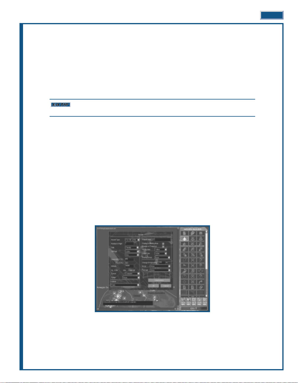
AIRFRAME/PILOT SELECTION
When you select an airframe you determine the actual fighters you and your wingmen are flying. All of the
fighters are F/A-18E Super Hornets. All are identical until they enter combat and take damage, or worse
yet, are lost. This is a real issue in the campaign setting where there are only a limited number of available
airframes.
Pilots are also a limited commodity and are much harder to replace. Like aircraft, they are not immune to being
wounded or lost in combat.
Different types of damage are repaired at different rates. It usually takes about two to five
missions for a damaged aircraft to become available again.
AIRCRAFT INFORMATION
Information on the status of each aircraft in the entire squadron (“Active,” “Damaged,” or “Destroyed”)
appears on the screen.
◆
◆ Click AIRCRAFT INFORMATION
PILOT INFORMATION
Information on the status of each pilot in the entire squadron (pilots are listed as “Active,” “MIA,” or “KIA”)
appears on the screen.
◆
◆ Click PILOT INFORMATION
ARMING
Campaigns require you to exercise a degree of resource management. You can’t afford to just burn up all
the best weapons on the milk-run missions. You must take care and plan for the future. That could be the
difference between success and failure. Remember the old axiom, “A horse, a horse, my kingdom for a
horse.” Don’t get caught short.
◆
◆ Click ARMING
WEAPON INVENTORY
This provides a list of the squadron’s current ordnance supplies. A “-“ character indicates the squadron has
unlimited access to that particular ordnance.
◆
◆ Click WEAPON INVENTORY
FLY MISSION
Notice in the Mission Briefing Screen that where you would expect to see the normal FORWARD indicator, a small
aircraft is substituted – this is the Fly Mission control. When you are satisfied with all elements, you’re ready to
jump in the pilot’s seat and take off.
◆
◆ Click FLY to begin the mission.
3-34 JANE’S F/A-18 FLIGHT MANUAL
Page 41

INTERFACE OVERVIEW 3-35
MULTIPLAYER
Jane’s F/A-18 is not just a single-player game with some multiplayer options attached as an afterthought. It’s a
multiplayer game in-and-out. Y ou can fly any mission type as a multiplayer mission. However, don’t think you must
have a human opponent; the missions are equally challenging in either mode.
Jane’s F/A-18 supports IPX/SPX network (LAN) play (up to eight players), TCP/IP network (Internet) play (up to
eight players), and modem and direct serial play (two players).
Notice that it is not necessary to click on the control word – click anywhere in the highlighted area to proceed.
Click one of the following options:
◆
◆ “Serial” sets up a connection by linking two computers together with a direct serial cable. See Direct Serial
(Null-Modem), p. 3-36.
◆
◆ “Modem” sets up a connection between two computers over a modem line. See Modem, p. 3-37.
◆
◆ “IPX/SPX Network” connects 2-8 computers over a LAN (Local Area Network). See IPX/SPX Network, p. 3-37.
◆
◆ “TCP/IP” connects up to 8 players with an Internet (dial-up) connection. See TCP/IP Network, p. 3-38.
◆
◆ “Main” returns to the Main menu.
If you have problems connecting with another player, refer to the If you Can’t Connect section that follows each
connection option, or consult your network supervisor, Internet service provider (ISP), or hardware/modem
documentation.
You can also get information on network and modem connections by going to the Windows 95/98 START menu
and clicking HELP.
◆
◆ Click on the CONTENTS tab, then double-click HOW TO.
◆
◆ For help with IPX/SPX connections, double-click USE A NETWORK.
◆
◆ For help with modem setup, double-click SET UP HARDWARE, then select SETTING UP A MODEM.
◆
◆ For help with TCP/IP connections, click the INDEX tab and type INTERNET in the box. Relevant topics are
highlighted in the large box below – click on a topic to view its information.
Page 42

DIRECT SERIAL (NULL MODEM)
If you and another gamer don’t own modems, have heart, you can still play Jane’s F/A-18 in multiplayer mode. You
can use a null-modem cable to link your two computers.
STEP 1 – CONNECTING YOUR MACHINES
A. Plug one end of the connector cable into a serial port on one machine, and the other end into a serial port on
the second machine. In some cases you may have to install drivers or software to use your null modem cable.
Please consult your computer’s documentation for more information.
B. You must know which COM port you connected to on each computer. Many computers have a label next to the
COM connector. The documentation that came with your computer may have a connection diagram with the
communication ports labeled. COM ports are numbered starting at “1” and up, i.e., COM1, COM2, COM3, etc.
STEP 2 – SERIAL PORT SETTINGS
A. From the MULTIPLAYER menu, click SERIAL.
B. A dialog box appears asking if you want to HOST or JOIN. The first computer selects HOST (you decide which
one of the your two computers is the first) and then creates a game session (see Hosting a Mission, p. 3-41).
The second computer then selects JOIN.
C. After clicking continue, the Serial Connection dialog box now appears. Select the correct COM port and use the
default settings for the remaining boxes, e.g., 57600 baud, 1-stop bit, no parity and RTS/DTR flow control.
When finished, click OK.
D. The JOIN computer will now be in the Game Sessions screen and should click ACCEPT.
IMPOR
IMPORTT
ANT
ANT::
The HOST computer must complete Step C before the JOIN computer completes
Step D.
STEP 3 – CONFIGURING THE MISSION
IF YOU CAN’T CONNECT
If you’re having problems connecting, you may have a hardware conflict. Two devices may think they’re occupying
the same COM port.
To check for port conflicts:
A. Click the Windows 95/98 START button.
B. Highlight SETTINGS.
C. Click CONTROL PANEL, then double-click the SYSTEM icon.
D. Click the DEVICE MANAGER tab.
E. Click inside the circle next to View Devices by connection. Check to make sure only one device is listed next
to the COM port you connect the cable to.
If your computer’s settings, the game’s settings and the other player’s settings are identical (you may have different
COM ports selected on the two computers) and you still experience problems, try selecting another COM port or
lowering the baud rate (as described in Step 2 – Serial Port Settings).
Make sure you know exactly which COM port you’re looking at and what you are deleting.
You certainly don’t want to delete anything important. Please contact your system manufacturer for help
with port conflicts. This may take some extra time, but it’s worth the effort.
3-36 JANE’S F/A-18 FLIGHT MANUAL
Page 43

MODEM
You can play another player across a 28,800-baud or faster modem.
STEP 1 – CONFIGURING THE MODEMS
Both players must verify that their modems are configured correctly to get a successful connection:
A. Exit to Windows 95/98 and click START. Highlight SETTINGS, then click CONTROL PANEL. Double-click on
the MODEMS icon.
B. Click the PROPERTIES button. Make sure the maximum speed is set to the highest level for your modem (at
least 57600 is recommended). Verify that the Only connect at this speed box is not checked.
C. Click the CONNECTIONS tab, then click the ADVANCED button.
D. Verify that there is not a checkmark in the Use flow control box. If there is a checkmark, remove it.
E. Verify that there is not a black dot next to Hardware (RTS/CTS). If there is a black dot, remove it.
If you’ve made any changes to your modem settings in the steps above, restart Windows
95/98 before trying to connect. This ensures the changes are saved.
STEP 2 – CONNECTING WITH ANOTHER MODEM PLAYER
A. From the MULTIPLAYER menu, click MODEM.
B. A dialog box appears asking if you want to HOST or JOIN. The first computer selects HOST (you decide which
one of your two computers is the first) and then clicks CONTUNE and then clicks the ANSWER button.
C. The other computer selects JOIN, enters the host’s phone number, and clicks CONTINUE.
D. The Modem Connection status box now appears. The missions should connect, allowing the host to setup the
mission.
CONFIGURE
As long as your modem is configured through Windows 95/98, you should not have any trouble. If you do have
difficulties, you can access the Windows 95/98 (Modem) Properties by clicking CONFIGURE on the Modem screen.
If your modem is not configured properly, please consult your modem and Windows 95/98 documentation.
STEP 3 – CONFIGURING THE MISSION
IF YOU CAN’T CONNECT
A. Make sure your modem is set up correctly under Windows 95/98 and that you don’t have multiple modem
drivers loaded.
IPX/SPX NETWORK
Two to eight players can “join” a specific game. Multiple sessions of Jane’s F/A-18 can run concurrently on a
network without disrupting normal network activity (during peak network hours, however, the game may run
more slowly).
IMPOR
IMPORTT
ANT
ANT:: You must have an IPX/SPX-compatible protocol loaded under Windows 95/98
(such a protocol ships with Windows 95/98). To check, go to the START menu, highlight SETTINGS, then
click CONTROL PANEL, and double-click the NETWORK icon. Scroll down in the box to see if any kind of
IPX/SPX-compatible protocol is listed.
◆
◆ From the MULTIPLAYER menu, click IPX. This takes you directly to the Game Sessions screen.
INTERFACE OVERVIEW 3-37
Page 44

3-38 JANE’S F/A-18 FLIGHT MANUAL
STEP 1 – CONFIGURING THE MISSION
IF YOU CAN’T CONNECT
If your computer can’t find other players on the network, verify you have an IPX/SPX protocol loaded (see
Important in IPX/SPX Network, just above).
TCP/IP NETWORK
You must have an account with an Internet service provider (ISP), LAN with TCP/IP protocol, or other access to
the Internet to play Jane’s F/A-18 through a TCP/IP connection.
All players need to exchange IP addresses with the host once they’re logged on to the Internet. It’s easiest to do this
if everyone logs on to a chat zone. If you do not know how to get into a chat zone, contact your Internet service
provider, or check their on-line help, if available.
If you have a web browser (e.g., Netscape Navigator or Microsoft Internet Explore), you can meet in the chat room
of the Jane’s Combat Simulations web page at http://www.janes.ea.com. To reach this room, click the Community
switch on the left side of the Jane’s home page. Click CHAT ROOM to get to the chat room.
STEP 1 – SETTING UP FOR INTERNET PLAY
A. Contact the other players (via chat board, telephone, etc.) and determine who has the fastest computer. This
person should be the host.
◆
◆ Also decide the number of players connecting.
B. The host needs to log on to the Internet. Find his IP address and communicate this address to the other players.
Remember, in most cases, each time you log on the Internet you’ll have a different IP address, so the host must
check this each time. This is a very important point, you can’t just check the first time, and then assume it
remains the same each time you log on to the Internet.
◆
◆ Without logging off of the Internet, double-click on My Computer. Typically, this is the icon that looks like a
computer on your desktop.
◆
◆ Double-click on the c: drive icon, then double-click on the Windows folder.
NONOTE:
TE: You may see a message warning you about modifying the contents of the Windows folder.
To continue past this message, click “Show Files”.
◆
◆ Double-click on WINIPCFG.EXE (Windows IP Configuration).
◆
◆ Write down the number in the box next to IP ADDRESS.
C. Once the host knows his IP address, he must communicate this to the other players.
STEP 2 – CONNECTING WITH OTHER PLAYERS
NONOTE:
TE: All participants must know the IP address of the host before setting up a TCP/IP game. (See
Step 1, above)
A. Log on to the Internet. Minimize or close your browser window and load Jane’s F/A-18 if you haven’t already
done so.
B. From the MULTIPLAYER screen, select TCP/IP. Then select JOIN.
C. Type in the host’s IP address. Click CONTINUE.
Page 45

STEP 3 – CONFIGURING THE MISSION
IF YOU CAN’T CONNECT
You must have a TCP/IP-compatible protocol loaded under Windows 95/98 (such a protocol ships with Windows
95/98). To check, go to the START menu, highlight SETTINGS, then CONTROL PANEL, and double-click the
NETWORK icon. Scroll down in the box to see if any knd of TCP/IP-compatible protocol is listed. If one isn’t listed,
you probably won’t be able to connect to your Internet service provider either. This is a good indication that
something is wrong with this connection option.
If you do have a TCP/IP-compatible protocol and are having no difficulty connecting to the Internet, but you are
unable to connect with other players:
◆
◆ Follow the steps for TCP/IP Network again, designating another computer as the host. (Try using the computer
with the fastest Internet connection – this may not be the fastest computer.)
DISCONNECTING
If you disconnect in any of the following ways, the game continues, even if you’re the host.
◆
◆ Pressing any key during the connection process. (Returns you to Jane’s F/A-18’s Main menu.)
◆
◆ Exit the mission. Pressing
s
.
CHATTING WITH OTHER PLAYERS
CHAT
During multiplayer missions, the CHAT control is active. It is used to send messages to the other human
players in the mission. You can keep the Chat screen open while you peruse or set up the mission, thus
keeping in constant communications with the other pilots.
You find this control on most screens – no searching required.
◆
◆ Click CHAT to send a message.
◆
◆ Type your message in the area provided.
◆
◆ Select the players to receive the message by placing a “checkmark” next to their name.
◆
◆ Press
e
to send your message.
◆
◆ Click the “x” to close the Chat window.
WHO’S THE HOST?
You have now decided if you’re going to host the upcoming game or join someone else’s game.
As you proceed, whether hosting or joining, the BACK button always returns you to the beginning of the process.
◆
◆ Click HOST to host a mission.
◆
◆ Click JOIN to join a mission.
INTERFACE OVERVIEW 3-39
Host Join
Page 46

HOSTING A MISSION
First thing, you must get some housekeeping chores out of the way. Your mission needs a name and the players
will need to know this name so they can find the mission. You also need to indicate your pilot’s name and the
mission squadron. Finally, you mark whether to pass or receive files.
This may seem like a great deal of information at first, but it’s actually quite simple to create.
◆
◆ Click FORWARD to proceed.
The Player and Game names are limited to no more than 19 characters each.
Note that the PILOT and SQUADRON names are selected from a drop-down list of the available choices. This
information is not typed in a text box.
Y ou now proceed to the Main Menu screen where you select the type of mission for the upcoming multiplayer game.
Single Mission or Campaign may be selected as the type of multiplayer mission. You’re not limited to any
particular type of mission.
Y ou now select the mission options just as you would if you were playing by yourself. However, in this case, you’re
determining the mission parameters for not only yourself, but for all the players in the mission.
Remember that the Chat function is active, so if you wish to check with another player on any issue, you can just ask.
◆
◆ Click FLY when you are satisfied with the mission parameters.
3-40 JANE’S F/A-18 FLIGHT MANUAL
Page 47

When the mission files have been transferred from the host to each joining player, they will have the opportunity
to preview the mission. Typically, the mission will begin as soon as each of the players hit the FLY button.
A courteous host will provide the joining players with the opportunity to review the mission objectives and aircraft
loadout. If for some reason a joining player neglects to click the FLY button within a reasonable amount of time,
the host has the ability to start the mission immediately.
DISCONNECT PLAYER
Clicking Disconnect player during chat immediately disconnects any selected player from the game.
CLOSE
Clicking Close removes the chat window.
JOINING A MISSION
This is a lot easier since you can sit back and watch the host do all the work. On the other hand, the down side is
that you don’t get to decide the mission parameters. There are always tradeoffs.
◆
◆ Click FORWARD to proceed.
Just like the Host screen, this screen requires a little housekeeping. The other players need to know your name so
they know who is out there. You also enter the telephone number or the IP address, if any. You need to indicate
your pilot’s name and the mission squadron. Finally, you mark whether to pass or receive files.
Your Player name is limited to no more than 19 characters.
Note that the PILOT and SQUADRON names are selected from a drop-down list of the available choices. This
information is not typed in a text box.
The IP address is not required, but if you know it, it’s best to enter the information as it may save you from
inadvertently joining the wrong game.
INTERFACE OVERVIEW 3-41
Page 48

WHAT TO PLAY?
You now have the option of selecting what game to join from the list of available games the players signed up for
action. The game names correspond to those entered by the hosts.
◆
◆ Click FORWARD after making your selection.
THE PARTY LINE
While you’re waiting for your connection, the Party Line screen displays. Y ou can chat with the other players while
you’re waiting.
You now proceed to the mission screen where you follow along with the host as the mission parameters are
selected.
You can make a few of your own selections, such as loadouts, but in most cases the host decides what to select.
Remember that the Chat function is active, so if you wish to check with the host, or any other player for that
matter, on any issue, just ask.
◆
◆ Click FLY when you are satisfied with the mission parameters.
Note that the mission doesn’t actually start until all players click the FLY button. Until then, you get to wait in the
Ready Room. Chat is fully functional while you are waiting.
3-42 JANE’S F/A-18 FLIGHT MANUAL
Page 49

TOOLS
The Tools menu includes three very important options that will enhance your enjoyment of Jane’s F/A-18.
The Squadron/Pilot Edit option enables you to add, edit, or delete squadron and pilot information without having to
first start a single or campaign mission.
Jane’s Reference is an invaluable tool that provides detailed information on the air, land, and sea units and their
weapons included in Jane’s F/A-18. Garnered from Jane’s vast bank of military data, Jane’s Reference contains the
most accurate and up-to-date information. If you have any questions on what something is, or what is its primary
function, this is the place to look.
The Mission Builder is one of the most impressive features you’ll find in Jane’s F/A-18. This isn’t just some hacked
together afterthought to fill space on the CDROM. You have access to the same tool that the designers of Jane’s
F/A-18 use to develop the missions included in the game – now that’s one powerful tool. Simple or complex, you
control all facets of the mission design. Exchange them with friends or save that “special” mission for that guy
who’s always bragging about his flight prowess – you decide.
MISSION BUILDER
See Chapter 6: Mission Builder, p. 6-147.
SQUADRON/PILOT EDIT
See Single Mission: Squadron Edit, p. 3-26 and Single Mission: Pilot Edit, p. 3-26 for a complete explanation
of these functions.
JANE’S REFERENCE
This reference screen provides information on all the planes and weapons included in Jane’ s F/A-18.It includes the
actual 3D models you’ll see out in the flight world and specifications and text describing each of the objects.
INTERFACE OVERVIEW 3-43
Page 50

◆
◆ Click the item you wish to view from the Object List.
Object List: A scrollable list of all the planes, objects, and weapons in the game.
3D Object Viewer: Click this tab to display an image of the object as it appears in the game. Use the green object
controls to adjust the position and view.
Reference: Provides the Jane’s Information Group’s data on the highlighted object.
Zoom In: Moves your point-of-view closer to the objects.
Zoom Out: Moves your point-of-view away from the object.
Rotate Heading: Rotates the object counter-clockwise (from a top-down perspective). This is primarily used
when Autorotate is off. Right-clicking rotates in a clockwise direction.
Rotate Pitch: Pulls down the object’s nose. Right clicking pulls the nose up.
Rotate Roll: Rotates the object along its axis, so that it rotates clockwise (from a nose on perspective). Right-
clicking rotates it counter-clockwise.
Autorotate: Toggles object rotation on/off.
Reset Orientation: Returns the object to its original pitch.
3-44 JANE’S F/A-18 FLIGHT MANUAL
Reference Tab
3D Object Viewer
Zoom In
Zoom Out
Rotate Heading
Rotate Pitch
Rotate Roll
Autorotate
Reset Orientation
Page 51

FFFFLLLLIIIIGGGGHHHHTT
TT
CHAPTER 4
Page 52

CHAPTER 4:
FLIGHT. . . . . . . . . . . . . . . . . . . 4-47
Wings of the Hunter. . . . . . . . . . . . . . . . . . . . . . . 4-47
The Cockpit - the Pilot’s Office . . . . . . . . . . . . . . 4-49
Cockpit Overview. . . . . . . . . . . . . . . . . . . . . . . . . 4-49
Engine Fuel Display (EFD) . . . . . . . . . . . . . . . . . 4-54
Head-Up Display (HUD). . . . . . . . . . . . . . . . . . . . 4-55
Basic HUD Symbology . . . . . . . . . . . . . . . . . . . . 4-55
HUD – NAV Master Mode Symbology. . . . . . . . . 4-56
HUD Landing & Steering Symbology . . . . . . . . . 4-56
HUD – A/A Master Mode Symbology. . . . . . . . . . 4-57
Weapon Independent HUD Symbology. . . . . . . . 4-57
HUD – A/G Master Mode Symbology . . . . . . . . . 4-58
Multi-Purpose Display Indicators (MDIs) /
Multipurpose Color Display (MPCD). . . . . . . . 4-60
Up-Front Controller . . . . . . . . . . . . . . . . . . . . . . . 4-81
Taking Off and Landing. . . . . . . . . . . . . . . . . . . . 4-84
Carrier Takeoff. . . . . . . . . . . . . . . . . . . . . . . . . . . 4-85
Land-Based Takeoff. . . . . . . . . . . . . . . . . . . . . . . 4-86
ILS – Instrument Landing System. . . . . . . . . . . . 4-86
Carrier Landing . . . . . . . . . . . . . . . . . . . . . . . . . . 4-87
Land-Based Landing . . . . . . . . . . . . . . . . . . . . . . 4-89
Navigation . . . . . . . . . . . . . . . . . . . . . . . . . . . . . . 4-90
Basic Terms. . . . . . . . . . . . . . . . . . . . . . . . . . . . . 4-90
TACAN Signals. . . . . . . . . . . . . . . . . . . . . . . . . . . 4-90
Navigating Waypoints & Target Points . . . . . . . . 4-91
Autopilot Modes . . . . . . . . . . . . . . . . . . . . . . . . . 4-91
Refueling . . . . . . . . . . . . . . . . . . . . . . . . . . . . . . . 4-91
Managing Your flight. . . . . . . . . . . . . . . . . . . . . . 4-92
4-46 JANE’S F/A-18 FLIGHT MANUAL
Page 53

CHAPTER 4:
CHAPTER 4:
FLIGHT
FLIGHT
Whether twisting in a nose-to-tail dogfight with a MiG or guiding a PGM (Precision Guided Munitions) through
the porthole of an enemy destroyer, air combat is often a one-on-one fight to gain the advantage over your
opponent. Understanding how and why your aircraft functions and maneuvers is key to success.
WINGS OF THE HUNTER
THE FCS
The F/A-18E’s flight control system (FCS) is a state-of-the-art fly-by-wire full authority control augmentation
system (CAS) – that’s certainly a mouth full.
What it means is that you’re in the seat of one hot aircraft. Its computerized flight controls enable you to put this
bird through its paces with little fear.
The FCS provides four basic functions: aircraft stability, aircraft control, departure resistance, and structural load
management. It continually monitors aircraft stability since the basic airframe is normally slightly unstable.
Inherently unstable aircraft respond more quickly to control inputs, resulting in a more maneuverable aircraft.
The FCS also provides full control of the aircraft by implementing the basic flight control laws in response to your
inputs. The stick and rudder pedals are not directly linked to the flight control surfaces such as the ailerons or the
twin tails. Instead, the controls send electrical impulses to two quad-redundant, digital flight control computers.
You have two in case one fails or suffers battle damage.
The computers instantaneously interpret your inputs and send commands to the appropriate flight control
surfaces to pitch, roll or yaw the aircraft as necessary. The FCS keeps an eye out for inputs from you that would
cause the aircraft to depart safe flight or would place undue stress on the airframe. If necessary, it may actually
override or modify your inputs.
All this activity takes place behind the scenes, without you ever noticing anything out of the ordinary. That’s the
beauty of the system. It works hand-in-hand with you, maximizing flight response to your inputs.
THE CONTROLS
The F/A-18E has a traditional center-mounted stick controlling pitch and roll. Since there isn’t any mechanical
linkage between the stick and the flight control surfaces, stick feedback is simulated by feel-spring assemblies and
eddy current dampers. The stick is also mass balanced to minimize longitudinal movement resulting from
acceleration during catapult launches.
T wo rudder pedals provide directional inputs for yaw and roll control. Feel-spring assemblies also provide feedback
for rudder input.
In the F/A-18F’s trainer configuration (the two-seat version of the “E” model), a control stick is fitted in the rear
cockpit that is mechanically linked to the pilot’s stick. Rudder pedals are also fitted in the rear cockpit, but are not
mechanically linked to the pilot’s rudder pedals. The inputs from both sets are combined and fed to the FCS.
FLIGHT CONTROL SURFACES
The F/A-18E has 14 primary flight control surfaces: including leading edge flaps (LEFs), trailing edge flaps (TEFs),
ailerons, twin tails, horizontal stabilizer, spoilers, and LEX vents. It’s more than one person could manage on a
good day. That’s why you have the two computers to crunch all the data.
For pitch and roll control, the LEFs, TEFs, ailerons, and stabilizers can move symmetrically (one complements the
other; e.g., when the left aileron deflects up, the right aileron deflects down a corresponding amount) or
asymmetrically (fully independent of the corresponding controls).
Pitch is controlled with the stabilizers and, in some conditions, with rudder toe-in or rudder flare. Roll is controlled
with combinations of aileron, asymmetrical stabilizers, LEFs and TEFs. The twin rudders deflect symmetrically
for yaw control.
The aircraft is not fitted with a traditional speedbrake. Depending on the mode, the “speedbrake function” is
achieved by partial deflection of several of the aircraft’s primary flight control surfaces.
FLIGHT 4-47
Page 54

FLIGHT ENVELOPE
Lift is a function of the aircraft’s speed, altitude, and angle-of-attack, and all of these factors work together to
produce flight. All three must be considered together when talking about how airplanes maneuver. Their limits are
graphically described by an aircraft’s flight envelope.
Above is the F/A-18E Super Hornet’s flight envelope diagram. The vertical scale represents altitude, in thousands
of feet, while the horizontal scale represents speed, in Mach Number. The solid line curves represent maximum
power thrust, while the dotted line curves represent military power thrust. Curve #1 describes an aircraft fitted
with 2-AIM-9 Sidewinders, 2-AIM-120 AMRAAMs and 60% fuel for a total weight of 42,200 pounds. Curve #2
describes an aircraft fitted with 4-AIM-9 Sidewinders, 2-AIM-120 AMRAAMs, a centerline fuel tank, an ATFLIR pod
and 75% internal fuel for a total weight of 46,500 pounds. As the Mach Number changes with altitude, the position
of the curve adjusts accordingly. Notice the huge amount of difference between these two curves. Also note that
the aircraft is only supersonic above 15,000 feet, even with a relatively light loadout, and only reaches maximum
speed at around 35,000 feet.
CAS OPERATING MODES
The Control Augmentation System operates in two basic modes: Powered Approach (PA) and Up-Auto (UA). Mode
selection is dictated by the position of the Flap switch and your aircraft’s airspeed.
With the flaps in the HALF or FULL position and airspeed below 240 kts, CAS sets flight controls tailored for
takeoff and landing conditions – PA mode.
With the flaps in the AUTO position, CAS sets flight controls tailored for up and away flight – hence the designation
Up-Auto.
If the flap switch is still in the HALF or FULL position when your airspeed increases above 240 kts, the CAS
automatically transitions from PA to UA. This is known as “auto flap retract.”
As a pilot aid, UA mode is constantly trimming the aircraft when the flight stick is in the neutral position. This
enables you to fly a steady-state, hands-free flight profile without having to constantly trim the aircraft.
The CAS also closely monitors pitch, roll and yaw states, applying stabilization or near departure commands to
the control surfaces to maintain the current flight profile or quickly respond to your inputs.
Either mode’s flight controls are maximized for maneuverability while maintaining predictable handling qualities
and departure conditions. This is no place for surprises; predictable responses are the rule, not the exception.
THE WORLD OF GS
The aircraft is designed to sustain a g-limit of +7.5G or -3.0G at or below a designed weight of 42,097 lbs. At higher
gross weights, the g-limit is reduced to keep from overstressing the airframe, such that at the aircraft’s maximum
gross weight (66,000 lbs.) the g-limit is only +4.8G to -1.9G.
The F/A-18E’s g-limiter essentially “limits” the amount of positive and negative G that you can command based on
the aircraft’s gross weight. Once you push the stick to the g-limit, further inputs are ignored. This is commonly
called “being on the limiter.”
4-48 JANE’S F/A-18 FLIGHT MANUAL
Page 55

Due to the aerodynamic phenomenon know as transonic pitchup, the g-limiter incorporates a “g-bucket” designed
to prevent over-g during transonic deceleration. The g-limiter only allows +5.8G to be commanded while in “the
g-bucket.”
You can enable the g-limiter override feature to allow a 33% increase in the g-limit for emergency situations –
allowing 10G at the 7.5G limit.
THE COCKPIT – THE PILOT’S OFFICE
The F/A-18E Super Hornet has a single cockpit, but what a cockpit. The most modern in the Navy arsenal, this
cockpit enables you to perform all the functions where most other aircraft require two crewmen.
Not that you’re overwhelmed with double the workload, it’s just that the F/A-18E is so sophisticated, you can
accomplish so much more in half the space.
Jane’s F/A-18 utilizes a 3D virtual cockpit, not a just a flat 2D image with unrealistic components pasted together.
Many cockpit functions are mouse “clickable” within this virtual environment. The remaining functions are
keyboard controlled or accessed through your joystick.
In this chapter, all keys are referred to by their names as they appear in the Custom Mapping
screen. Keyfunction names are in bold-caps, for example MASTER_MODE_CYCLE.
COCKPIT OVERVIEW
The cockpit features a Head-Up Display (HUD), an Up Front Controller (UFC), two monochrome Multipurpose
Display Indicators (MDI), a Multipurpose Color Display (MPCD), an Electronic Fuel Display (EFD), and several
conventional standby instruments.
◆
◆ HUD: The HUD consists of flight, targeting, and weapon information that is projected on a specially coated sheet
of glass located directly in front of the pilot. The various HUD modes are described separately in the Head Up
Display (HUD) section. See HUD p. 4-55.
◆
◆ Angle of Attack (AOA) Indexer: The AOA indexer displays the AOA during landing approach using lighted symbols.
The indexer operates when the landing gear is down and weight is off the gear.
FLIGHT 4-49
HUD
Angle of Attack Indexer
Left Warning/Cautions/
Advisory Light panel
Master Caution
Left Engine Fire Warning Light
Fire Extinguisher
Master Mode Pushbuttons
Master ARM Switch
Left MDI UFC HUD Control Panel EMCON Switch
Right Warning/Caution/
Advisory Light Panel
AFU Fire Warning Light
Right Engine Fire
Warning Light
Right MDI
IR Cooling Switch
Spin Recovery Switch
Page 56

Airspeed: Slow AoA: 9.3 to 90.0 degrees
Airspeed: Slightly Slow, AoA: 8.8 to 9.3 degrees
Airspeed: On speed, AoA: 7.4 to 8.8 degrees
Airspeed: Slightly Fast, AoA: 6.9 to 7.4 degrees
Airspeed: Fast, AoA: 0 to 6.9 degrees
◆
◆ Warnings/Cautions/Advisory Lights: The Warnings/Cautions/Advisory lights on either side of the HUD have the
following meanings:
Left Panel
L BLEED / R BLEED A bleed air leak has been detected on the left / right engine. If you don’t shut down the
engine, you run the risk of an engine fire.
SPD BRK The speed brake function is active.
BRAKES The wheel brakes are engaged.
L BAR The launch bar is extended and connected to the carrier’s catapult system.
DUMP The Fuel Dump is open and fuel is being vented from the aircraft.
REC The ASPJ internal jammer is in receive-only mode (EMCON limited).
XMIT The ASPJ internal jammer is transmitting.
AUTO The autopilot is active.
Right Panel
LASER The targeting FLIR laser designator is active.
DPLY An ALE-50 decoy is deployed.
AI A threat Airborne Interceptor has been detected.
CW Continuous Wave illumination from a threat missile guidance radar has been detected.
DISP The ALE-47 CMDS is dispensing chaff / flares.
DCOY ON The ALE-50 Decoy is transmitting.
SAM A threat surface to air missile system has been detected.
AAA A threat anti-aircraft artillery system has been detected.
◆
◆ Master Caution Light: The Master Caution light comes on when any new system failures are detected by the
aircraft’s Built-In-Test (BIT) system. Depressing the Master Caution light resets the light. Holding the button
down for more than three seconds brings up the BIT MDI page to be displayed in the left MDI.
◆
◆ Engine Fire Lights: The left or right engine fire light illuminates whenever a fire is detected in the left or right
engine bay, respectively. Each light is also a guarded pushbutton. Initially clicking on a fire light raises the
guard. Clicking on the button again with the guard up shuts off main fuel valve of that engine and arms the fire
extinguishing system (see below).
◆
◆ APU Fire Light: The APU fire light illuminates whenever a fire is detected within the auxiliary power unit (APU).
The APU fire light is also a pushbutton, and when clicked on it arms the fire extinguishing system (see below).
◆
◆ Fire Extinguisher: The Fire Extinguisher pushbutton is used to activate the aircraft’s onboard fire suppression
system. When the system is armed, the READY light is on. Clicking on the pushbutton releases the contents of
the fire extinguisher bottle into the selected engine / APU bay(s). If more than one Fire light is depressed,
4-50 JANE’S F/A-18 FLIGHT MANUAL
Page 57

extinguishing agent is distributed evenly to all selected bays, but the concentration may be insufficient to
extinguish all fires. Once the bottle has been discharged, the DISCH light comes on. Note that the extinguisher
can only be used once.
◆
◆ Master Mode Pushbuttons: The controls, displays and avionics equipment are tailored to operate in one of three
specific modes: Air-to-Air (A/A), Air-to-Ground (A/G) or Navigation (NAV) – the Master Modes. Master Modes
tailor the F/A-18’s avionics for specific functions. These pushbuttons indicate the current Master Mode. If A/A
Master Mode is selected, the A/A pushbutton illuminates. If A/G Master Mode is selected, the A/G pushbutton
illuminates. Notice that NAV Master Mode has no pushbutton; it is selected when neither A/A nor A/G Master
Modes are selected. Master Mode can be changed either by clicking on the appropriate button, or by using the
MASTER_MODE_CYCLE [
M
] keyfunction to cycle through each of the Master Modes.
◆
◆ Master Arm switch: The Master Arm switch enables or disables the release of weapons.
◆
◆ Left / Right MDI: The Multipurpose Display Indicators are used to display various flight, targeting and weapons
information. Twenty clickable pushbuttons surround each MDI. They are grouped in banks of five and are
numbered starting at the lower left, moving clockwise around each display.
The various MDI pages are described separately in the MDI/MPCD section. See MDI/MPCD, p. 4-60
◆
◆ UFC: The Up Front Controller is a programmable, touch sensitive display that is used to control certain avionics
systems. The various UFC formats are described separately in the UFC section. See Up Front Controller (UFC),
p. 4-81.
◆
◆ EMCON Pushbutton: The EMCON (short for Emissions Control) pushbutton is used to limit / allow any emission
that might give away the position of your aircraft. When EMCON is selected, the radar is placed in Silent mode
and both the ASPJ and the ALE-50 decoy are placed in Standby. When EMCON is deselected, the radar and
jammers may transmit freely.
◆
◆ HUD CONTROL PANEL: The HUD control panel is used to control various HUD functions.
FLIGHT 4-51
PB7
PB6
PB5
PB4
PB3
PB2
PB1
PB20
PB10
PB11
PB12
PB13
PB14
PB15
PB16
PB8 PB9
PB19 PB18 PB17
Symbol Reject Switch Symbol Brightness Control Knob Altitude Switch NAVFLIR Video Switch
Page 58

●
●
Symbol Reject Switch: A three-position switch, clicking cycles between NORM, REJ 1 and REJ 2 positions.
• NORM: normal HUD format.
●
●
REJ1: removes the following symbology from the HUD (if present):
• Aircraft Mach number
• Aircraft G’s
• Peak positive Gs
• Bank Angle scale and pointer
●
● REJ 2: Removes REJ 1 symbology plus the following (if present):
• Heading scale
• Command heading
• Heading caret
• NAV range
• ETA / TOD Timer / Clock
●
● Symbol Brightness Control: Clicking on the knob cycles between each HUD color. The HUD_COLOR [H]
keyfunction is also used to select the HUD color.
●
● NAVFLIR Video Switch: Clicking toggles between OFF, WHT, and BLK.
• BLK: Selects black-hot for the NAVFLIR video on the HUD.
• WHT: Selects white-hot for the NAVFLIR video on the HUD.
• OFF: Removes NAVFLIR video from the HUD.
●
●
The keyfunction NAVFLIR_MODE [N] is also used to control the display of NAVFLIR video on the HUD.
●
●
Altitude Switch: Clicking toggles between BARO and RDR positions.
• BARO: Sets barometric altitude on the HUD.
• RDR: Sets Radar Altitude on the HUD, if valid and less than or equal to 5,000 feet AGL.
◆
◆ Spin Recovery Switch: The Spin Recovery switch is not used on the real F/A-18E and has no function in the game.
◆
◆ IR Cooling Switch: The IR cooling switch is not functional in Jane’s F/A-18.
◆
◆ MPCD: The Multipurpose Color Display (MPCD) is a larger, full color version of an MDI and is used to display
the same type of information. Twenty clickable pushbuttons surround the MPCD, which are numbered in the
same manner as the MDI. The various MPCD pages are described separately in the MDI/MPCD section. See
MDI/MPCD, p. 4-60.
◆
◆ EFD: The Electronic Fuel Display (EFD) is the primary Fuel/Engine display in the cockpit. It is described
separately in the EFD section. See EFD, p. 4-54.
4-52 JANE’S F/A-18 FLIGHT MANUAL
MPCD
EFD
Jettison Initiate Pushbutton
Station Selection
Pushbuttons
Landing Gear Handle
Flap/Landing Gear
Status Lights
External Stores Jettison
Selection Knob
Heading Select Switch
Course Select Switch
Attitude Reference
Indicator
Tailhook Handle
Vertical Speed Indicator
Standby Altitude
Indicator
Standby Airspeed
Indicator
Refueling Probe Switch Anti-collision Lights Switch Formation Lights Switch Flaps switch Analog Clock
Page 59

◆
◆ Jettison Initiate Pushbutton: The Jettison Initiate pushbutton releases external stores based upon the settings of the
External Stores Jettison selection knob and the Station Selection pushbuttons.
◆
◆ Station Selection Pushbuttons: The seven Station Selection pushbuttons are used to select individual weapons
stations for jettison. Any number of these stations can be selected at a time. The seven pushbuttons are CL
(Centerline), LI (Left Inboard), LM (Left Middle), LO (Left Outboard), RI (Right Inboard), RM (Right Middle),
and RO (Right Outboard).
◆
◆ External Stores Jettison Selection Knob: The External Stores Jettison selection knob is used to select the function of
the Jettison Initiate pushbutton. The knob is rotated to select EMERG, SAFE, L FUSE MSL, R FUSE MSL, or
STORES settings.
• EMERG: Selects all external stores for Jettison. Note that the following stores cannot be jettisoned: wingtip
AIM-9’s, FLIR pods, and the Data Link pod.
• SAFE: Deactivates the Jettison Initiate pushbutton.
• L FUSE MSL: Selects the Left fuselage missile station (Station 5) for jettison.
• R FUSE MSL: Selects the Right fuselage missile station (Station 7) for jettison.
• STORES: Enables the selective jettison of stores in conjunction with the Station Selection pushbuttons.
◆
◆ Landing Gear Handle: The landing gear handle raises or lowers the landing gear. The LANDING_GEAR [
G
]
keyfunction is also used.
◆
◆ Landing Gear / Flaps Status Lights: The Landing Gear / Flaps status lights display the current landing gear and wing
flaps status. The top three lights (NOSE, LEFT and RIGHT) illuminate when the landing gear is down and
locked. The FLAPS light illuminates when the trailing edge flaps are deployed in Auto Flaps Mode. The HALF
and FULL lights illuminate when either Half or Full flaps, respectively, are selected.
◆
◆ Heading Select Switch: The Heading Select switch is used to change the heading bug on the HSI MDI/MPCD page.
See MDI/MPCD: HSI page, p. 4-60.
◆
◆ Course Select Switch: The Course Select switch is used to change the course line on the HSI MDI/MPCD page.
See MDI/MPCD: HSI page, p. 4-60.
◆
◆ Refueling Probe Switch: The Refueling Probe switch is used to extend or retract the airborne refueling probe. The
keyfunction REFUELING_PROBE [
Q
] is also used to control the probe.
◆
◆ Anti-Collision Light Switch: The Anti-Collision light switch is used to turn the external anti-collision lights on and
off. The LIGHTS_ANTICOLLISION [
K
] keyfunction is also used to control these lights.
◆
◆ Formation Light Switch: The Formation light switch is used to control the external formation lights. The switch is
toggled between OFF, DIM, and BRT (bright) settings. The LIGHTS_FORMATION [
q-K
] keyfunction is
also used to control these lights.
◆
◆ Analog Clock: The analog clock is provided as a backup. It requires no electrical power to operate.
◆
◆ Standby Airspeed Indicator: The Standby Airspeed Indicator operates off of pitot-static pressure and requires no
power. It registers indicated airspeed between 0 and 800 knots.
◆
◆ Standby Altimeter: The Standby Altimeter operates from a static pressure source and requires no power. This
altimeter indicates the current barometric altitude of the aircraft.
◆
◆ Vertical Speed Indicator: The Vertical Speed Indicator registers the current rate of altitude gain or loss. When the
needle is horizontal, the aircraft is level. If the aircraft is climbing, the needle deflects upwards. If the aircraft
is descending, the needle deflects downwards.
◆
◆ Tail Hook Switch: The Tail Hook switch is used to raise or lower the aircraft’s tail hook. The keyfunction
TAILHOOK [
T
] is also used to raise or lower the tail hook.
◆
◆ Attitude Reference Indicator: The Attitude reference indicator is a self-contained, electrical gyro-horizon
instrument that indicates the aircraft’s attitude relative to the horizon.
◆
◆ Lock / Shoot Lights (not shown): The Lock / Shoot lights are located on the canopy frame directly above the HUD.
When the radar has locked on to a target, the LOCK light illuminates. When the Shoot cue is displayed on the
HUD, the SHOOT light illuminates.
FLIGHT 4-53
Page 60

ENGINE FUEL DISPLAY (EFD)
The Electronic Fuel Display (EFD) is the primary Fuel/Engine display in the cockpit. The amount of onboard fuel
is displayed in addition to key engine parameters. The only interactive control on the EFD is the Bingo level
selection, which is adjusted via a rotating knob on the upper left side of the display.
The Bingo level is adjusted (in 500 lbs. increments) using either the Bingo knob (clicking the “-“ under the knob
decreases the value, while clicking the “+” increases it).
◆
◆ Total Fuel: Displays the total (internal + external) fuel currently loaded on/in your aircraft in thousands of
pounds, to the nearest hundred pounds.
◆
◆ Bingo Setting: Displays the current low fuel “bingo” warning in thousands of pounds, to the nearest hundred
pounds. The bingo level is set as described above.
◆
◆ External Fuel Total: Displays the total external fuel currently loaded on your aircraft in thousands of pounds, to
the nearest hundred pounds.
◆
◆ Left/Right Engine N2 RPM: Displays N2 compressor RPM (expressed as a percent) for each engine. The left column
represents the left engine, while the right column represents the right engine.
◆
◆ Left/Right Engine Exhaust Gas Temperature (TEMP): Displays exhaust gas temperature for both engines in degrees
Celsius.
◆
◆ Fuel Flow (FF): Displays Fuel Flow to each engine in hundreds of pounds per hour.
◆
◆ Oil Pressure: Displays left and right engine oil pressure in PSI.
◆
◆ Engine Nozzle Position (NOZ) Area: Graphically (circles) and digitally (percent) displays the current positions of
each engine’s exhaust nozzle. As the nozzles close, the circles progressively fill.
◆
◆ External Fuel Tanks Display: Graphically displays the five potential external tanks as individual boxes in the EFD.
The amount of fuel in each tank is indicated both as a number below each box (in thousands of pounds to the
nearest hundred pounds) and graphically by the amount each box is filled.
◆
◆ Internal Fuel Total: Displays the total amount of internal fuel currently loaded on your aircraft.
◆
◆ Internal Fuel Tank: Graphically displays all internal fuel as a single box on the EFD. The amount of fuel is
indicated by the amount the box is filled.
◆
◆ Bingo Bug Setting: Graphically displays the current setting of the low fuel “bingo” warning as an arrow on the left
hand side of the total internal fuel box.
4-54 JANE’S F/A-18 FLIGHT MANUAL
Total Fuel
Bingo Setting
External Fuel Total
Left/Right Engine N2 RPM
Left/Right Engine EGT Temperature
Left/Right Fuel Flow
Left/Right Engine Oil Pressure
Bingo Bug Setting
Internal Fuel Tank Display
Internal Fuel Total
External Fuel Tanks Display
Engine Nozzle Position
Page 61

HEAD-UP DISPLAY (HUD)
The HUD consists of computerized flight, targeting, and weapons information projected onto an eye-level sheet of
specially coated glass at the front of the cockpit. It’s designed to keep the pilot from having to constantly look down
at his instruments (hence the name “head-up”) for flight and combat information. It is a good thing to have when
locked in a wild dogfight.
BASIC HUD SYMBOLOGY
The basic HUD symbology is common to all three Master Modes.
◆
◆ Heading Scale: Displays your current heading. The Heading Scale is basically a digital compass laid out on a
horizontal tape. North is 000, east is 090, south is 180 and west is 270. The heading numbers are displayed every
10 degrees over the large tick marks. A total of 30 degrees is displayed at one time on the moving tape.
◆
◆ Airspeed: Displays your current indicated airspeed.
◆
◆ Angle of Attack: Displays your current angle of attack in degrees.
◆
◆ Mach Number: Displays your current mach number.
◆
◆ Aircraft G: Displays the number of Gs you’re current pulling.
◆
◆ Peak Aircraft G: Displays the maximum attainable G the aircraft is allowed to generate based on correct weight
and the G-override limiter.
◆
◆ Flaps Mode: The current Flap mode (Auto, Full, or Half) is displayed here.
◆
◆ Pitch Ladder: The Pitch Ladder lines are drawn every five degrees and angle in towards the horizon at an angle
half that of the flight path angle. For example, in a 40° climb, the pitch lines are angled 20° toward the horizon.
• Positive pitch lines are solid, and negative pitch lines are dashed. Each line is numbered, and the numbers
rotate with roll so that inverted flight is easily recognized.
◆
◆ Velocity Vector: The velocity vector (also called the flight path indicator) points to the actual direction the aircraft
is flying. For example, with heavy rudder use, the nose of the aircraft may point in one direction while the
aircraft side-slips in another direction.
• The velocity vector is limited to an 8° radius circle, so if it reaches this limit during flight, it flashes rapidly
denoting it is no longer accurately indicating the flight path.
◆
◆ Selected Waypoint: Displays the currently selected waypoint.
◆
◆ Distance to Waypoint: Displays the current distance, in nautical miles, to the currently selected waypoint.
◆
◆ Altitude: Displays either the barometric or radar altitude depending on the setting of the ALT switch on the HUD
control panel. When the switch is in the BARO position, barometric altitude displays; in the RDR position,
radar altitude displays and is indicated by an R next to the altitude.
FLIGHT 4-55
Heading scale
Airspeed
Angle of Attack
Mach Number
Aircraft G
Peak Aircraft G
Flaps Mode
Heading Bug
Altitude
Velocity Vector
Distance to Selected Waypoint
Selected Waypoint
Pitch Ladder
Page 62

• RDR is only valid at or below 5,000 feet AGL. If the radar altitude is or becomes invalid when selected for
display, barometric altitude displays and a “B” flashes next to the altitude to indicate that barometric altitude
is displaying rather than radar altitude.
• The current Vertical Velocity, in feet per minute, displays above the altitude box only in NAV Master Mode.
Negative values indicate descent.
◆
◆ Heading Bug: The heading bug indicates the bearing to the currently selected waypoint, target, or TACAN station,
depending upon which steering mode is selected on the HSI.
HUD – NAV MASTER MODE SYMBOLOGY
In addition to the basic HUD symbology, the NAV Master Mode adds Landing and Steering symbology.
HUD LANDING & STEERING SYMBOLOGY
With the NAV Master Mode set and the landing gear down, the HUD displays the landing information. The Mach
Number, Aircraft Gs and Peak Gs are deleted.
The steering information can display on the basic or landing HUD formats. The current steering mode is selected
on the HSI page. See MDI/MPCD: HSI page, p. 4-60.
◆
◆ Horizon Bar: Extends across the HUD.
◆
◆ Angle-of-Attack (AOA) Bracket: The AOA Bracket displays adjacent to the left of the Velocity Vector. It’s in addition
to the normal digital AOA. The center of the bracket represents the optimum approach angle-of-attack (8.1°
true). The length of the bracket is about ±1.2°. The bracket moves lower than the Velocity Vector as AOA
increases; it moves higher as AOA decreases.
◆
◆ Bank Angle Scale: Indicates your current bank angle in degrees from the horizontal. Tick marks represent 5, 15,
30, and 45 degrees of roll.
◆
◆ ILS Glideslope Bar: It’s a “fly-to” symbol linked to the Velocity Vector that displays aircraft position above, on or
below the Glideslope when landing. The ILS Glideslope bar is only displayed when the ILS is turned on.
◆
◆ Distance to Carrier: When ACL steering is selected, the distance to your home aircraft carrier in nautical miles is
displayed here.
◆
◆ Steering Mode: The current steering mode selected on the HSI is displayed here.
◆
◆ Autopilot Mode: If the autopilot is engaged, the current autopilot mode selected on the UFC is displayed here.
◆
◆ HUD Data Link & Advisory Messages: HUD data link advisory messages can appear on the HUD when ACL steering
is selected in NAV master mode. These messages are:
• NOT CMD: Indicates you’re not within the ACL control area (i.e. you’re too far from the ship) or your aircraft
is not capable of ACL landings (probably as a result of battle damage).
• LND CHK: Indicates you’re within the ACL control area but not configured for landing (gear and hook down).
4-56 JANE’S F/A-18 FLIGHT MANUAL
ILS Localizer
Horizon Bar
ILS Glideslope Bar
AoA Bracket
Bank Angle Scale
Waterline Symbol
Data link Advisory Messages
Autopilot Mode
Steering Mode
Distance to Carrier
Page 63

• ACL RDY: Indicates you’re within the ACL control box, configured for landing, and ready to be coupled (via
the autopilot).
• CMD CONT: Indicates the ACL system is in control of your aircraft.
• W/O: Indicates you’re to terminate the approach and go around. When this message is received, the ACL
system uncouples from the autopilot, and control of the aircraft reverts back to you.
◆
◆ ILS Localizer Bar: It’s a “fly-to” symbol linked to the Velocity Vector that displays aircraft position left of center,
on centerline or right of center when landing. The ILS Localizer bar is only displayed when the ILS is turned on.
◆
◆ Waterline Symbol: The aircraft waterline position is indicated on the HUD (4° above the optical center) by
displaying the flying W symbol. The waterline symbol is displayed when the landing gear is down.
HUD – A/A MASTER MODE SYMBOLOGY
The A/A HUD has its own weapon independent symbology that is described here. This section is not intended to
show all of the A/A HUD symbology; rather, it is meant to give you a basic idea of what to expect in A/A Master
Mode. In addition to this common A/A HUD symbology, radar target acquisition and weapon specific symbology
can be displayed on the HUD (described in the A/A Radar and A/A Weapon sections in Chapter 5 – Combat).
WEAPON INDEPENDENT HUD SYMBOLOGY
Weapons independent symbology is symbology that is common to all A/A missiles. The A/A HUD gun modes also
use some of this symbology.
◆
◆ SHOOT Cue: The SHOOT cue displays above the target designator (TD) box when all shoot conditions for the
selected weapon are met. The shoot cue flashes when the target is within “no escape” range and weapon
intercept is optimal.
◆
◆ Target Designator Box: The target designator (TD) box is a square that identifies the line of sight (LOS) to the
Launch & Steering (L&S) target. The TD box flashes when the L&S target LOS is outside the HUD FOV. Targets
identified as friendly will have an X through the center of the box.
◆
◆ Secondary Target Line-of-Sight Cue: In the Track-While-Scan radar mode, it is possible to track both a primary and
secondary target at the same time. If a secondary (also known as a DT2 target) exists, a small X is displayed to
represent the DT2 target LOS.
◆
◆ Normalized In-Range Display (NIRD) / Allowable Steering Error (ASE) Circle: The NIRD/ASE circle consists of a 6°
diameter circle centered at the aircraft waterline. The individual elements of the NIRD circle are described
separately below. The NIRD circle will not appear unless there is a L&S target.
◆
◆ Weapon Selected and Quantity Remaining: Indicates the currently selected weapon, followed by the number of the
selected weapon remaining. When the gun is the selected weapon, the number of gun rounds remaining is
displayed underneath the “GUN” text. An X through the selected weapon indicates that Master Arm is set to SAFE.
FLIGHT 4-57
Shoot Cue
Target Destination Box
Secondary Target Line-of-Sight Cue
NIRD/ASE Circle
Weapon Selected and Quantity Remaining
Steering Dot
Target Range Rate
Target Range
Page 64

◆
◆ Target Range: T arget range displays whenever there is an L&S target. The target range is displayed to the nearest
tenth of a nautical mile.
◆
◆ Target Range Rate: Target range rate (VC) in knots displays whenever there is an L&S target. A closing velocity
(target getting closer to you) is a positive number and an opening velocity (target getting further away from
you) is a negative number.
◆
◆ Steering Dot: A steering dot displays whenever an A/A missile is selected, an L&S target is designated and is it
located within 76° of aircraft boresight. The steering dot, in conjunction with the NIRD circle, provides lead
angle steering. Flying the aircraft so that the steering dot is inside the NIRD circle satisfies the lead angle
computation. The steering dot flashes when the target is within 15° of the A/A radar azimuth limit of ±70° or
within 5° of the elevation limit of ±60°. When AIM-9 is selected and the AIM-9 is tracking a target other than
the L&S, the steering dot is removed.
◆
◆ Breakaway X (not shown): The breakaway X is displayed when the range to the target is less than R
MIN
for the
selected weapon. You must either change weapons or increase the range between your aircraft and the target.
NORMALIZED IN-RANGE DISPLAY (NIRD) CIRCLE
◆
◆ Relative Range Bar: The relative range of the target is displayed by the bar just inside the NIRD circle. It starts at
the 12 o’clock position and rotates clockwise as target range increases. It’s scaled relative to R
AREO
and R
MIN
.
◆
◆ Maximum Aerodynamic Range (R
AERO
): R
AERO
is the absolute maximum straight-line range of the missile. Hitting
the target at this range is only possible if the target flies completely straight and level during the entire time of
flight of the missile.
◆
◆ Maximum Launch Range (R
MAX
): R
MAX
is the maximum range of the missile against a target that flies straight and
level during most of the missiles time of flight, and then performs a terminal escape maneuver just before the
missile reaches it.
◆
◆ No Escape Range (R
NE
): The estimated no-escape range represents the optimal firing range against a maneuvering
target. You are much more likely to get a hit if you wait until the target is within this range.
◆
◆ Minimum Launch Range (R
MIN
): The minimum launch range for the missile; a missile fired within this range will
probably not hit the target. Once the target is within R
MIN
, a large flashing Breakaway X will appear on the
HUD (and on the radar MDI).
◆
◆ Gun Maximum Range: When the radar is in STT, the gun R
MAX
tab displays on the NIRD circle to indicate the
maximum effective range of the gun. The gun R
MAX
marker only displays when in STT, an A/A missile is
selected, and target range is less than 12,000 ft.
HUD – A/G MASTER MODE SYMBOLOGY
When the A/G Master Mode is selected, target location and weapon release cues are added to the HUD. Much of
this symbology is common to all A/G weapons and is described here. Again, this section is not intended to show
all of the A/G HUD symbology; rather, it is meant to give you a basic idea of what to expect in A/G Master Mode.
Along with this common A/G HUD symbology , additional weapon specific symbology can display on the HUD. This
additional symbology is described in the A/G Weapon section of Chapter 5 - Combat.
4-58 JANE’S F/A-18 FLIGHT MANUAL
Relative Range Bar
Maximum Aerodynamic Range (R
AERO
)
Minimum Range (R
MIN
)
Gun Maximum Range
No Escape Range (R
NE
)
Maximum Range (R
MAX
)
Page 65

HUD BASIC A/G SYMBOLOGY
◆
◆ Release Cue: The release cue is a small line perpendicular to and centered on the Azimuth Steering Line (ASL).
It displays when a target is designated in the AUTO bomb mode or the HARM pre-briefed (PB) mode. Initially,
the release cue appears on the ASL above the velocity vector. As the weapon release point is approached, the
release cue moves with the ASL. When the release cue intersects the velocity vector, which is positioned on the
ASL through aircraft steering maneuvers, and the pickle button is depressed, automatic weapon release is
initiated. If steering error exceeds 20°, the release cue is blanked and release is inhibited in the AUTO mode.
◆
◆ Azimuth Steering Line (ASL): The ASL provides a steering cue to the designated target. The ASL displays after target
designation in the AUTO mode. The ASL always displays perpendicular to the horizon and provides an azimuth
steering reference with respect to the velocity vector.
◆
◆ Target Designator (TD) Diamond: The TD diamond is used to identify target line of sight in all A/G weapon delivery
modes. It contains a pipper in its center as an aiming reference whenever the TDC is assigned. The TD diamond
is used in conjunction with the TDC to designate targets and is movable over the total HUD field of view. After
designation, this symbol displays the computed position of the A/G designated target. The initial HUD TD
designation is performed by assigning the TDC to the HUD, moving the TDC to the desired position on the
HUD, and selecting the designate keyfunction.
• If the computed line of sight to the designated target lies outside the HUD field of view, the TD diamond is
limited on the HUD along the edge to the designated target and flashes indicating the limit condition. The TD
diamond is blanked when the bearing to the designated target exceeds 90°.
◆
◆ Range to Target: When there is an Air-to-Ground designated target and TGT steering is selected, the range to the
target is displayed here.
◆
◆ Frag Cue: The frag cue represents the edge of the predicted fragmentation envelope for the selected weapon. To
avoid the fragmentation envelope (and the possibility of severe aircraft damage), make sure this line is below
the velocity vector when the weapon detonates. During low altitude weapon deliveries, you may be below the
frag cue when you release your weapons. In this case, make sure you are flying very fast (above 600 knots is a
good rule of thumb) or get above that altitude before the weapon goes off.
◆
◆ Release Time-To-Go (REL): When a target is designated in AUTO mode or in HARM PB mode, this two-digit
readout indicates the number of seconds remaining until weapon release occurs (## REL). REL is blanked
when the steering error exceeds 20° in AUTO mode.
• For guided weapons such as Walleye and Maverick, the Time To Maximum Range (## TTMR) is displayed
instead of TTG. If the computed TTMR exceeds 99 seconds, the display is limited until the TTMR becomes
less than this value.
• In the A/G gun and rocket modes, the number of rounds remaining displays in this location rather than the
TTG or TTMR (GUN ### or RKT ###).
FLIGHT 4-59
Release cue
Azimuth Steering Line
Frag cue
Mode/Weapon Indicator
Release Time-to-Go Counter
Range to Target
Target Designator Diamond
Page 66

◆
◆ Mode / Weapon Indication: When any weapon except Walleye, Maverick, Harpoon, HARM, SLAM, JSOW, or JDAM
is selected, the selected delivery mode (AUTO, CCIP, or MAN) indicates on the HUD.
• When a Walleye, Maverick, Harpoon, HARM, SLAM, JSOW, or JDAM is selected, the MDI weapon
abbreviation identifying the weapon is displayed in this location. For the AGM-65E Laser Maverick, an
additional indication displays when it is locked on (MAV LKD).
◆
◆ Displayed Impact Line (DIL) (CCIP bombing mode only): The solid line DIL displays in CCIP bombing mode. The DIL
extends between the velocity vector and the center of the CCIP. It provides a steering reference to aid you in
maneuvering the aircraft to position the CCIP cross on the target. If the CCIP cross is not present, the DIL
extends to the HUD FOV.
◆
◆ Continuously Computed Impact Point (CCIP) (CCIP bombing mode only): This symbol displays only in the CCIP bombing
mode. It indicates the impact point of the selected weapon if the weapon release button were immediately
pressed. If the current weapon impact point is not in the HUD FOV, the CCIP cross is not displayed, and a
reflected cue displays on the DIL. In this case, the DIL displays to the HUD FOV limit in the direction of the
computed impact point, and the reflected cue displays. The reflected cue is a line displayed along the DIL at the
same distance above the bottom of the DIL (HUD limit point) as the actual distance the CCIP is below the HUD
limit point.
If the flight profile is flown so as to keep the target above the reflected cue, then a solution is ensured. During
a dive, the reflected cue moves down the DIL and is blanked when the CCIP cross appears. If the actual CCIP
is so far below the HUD that the reflected cue would be at or above the velocity vector, then the reflected cue is
blanked from the display.
MULTIPURPOSE DISPLAY INDICATORS (MDIS) /
MULTIPURPOSE COLOR DISPLAY (MPCD)
The Multi-Purpose Display Indicators (MDIs for short) along with the HUD are your primary sources of
information. They display interchangeable information on a series of screens called “pages”. From the MDI Main
menu, you can click on any of series of 20 buttons (called pushbuttons – PBs) surrounding the MDI to display the
different pages.
Some pages are only available under certain circumstances. Unavailable pages have their labels removed (and
associated pushbutton disabled) from the top-level menu page. The format of a page may also change based on the
selected Master Mode (radar is an example of this).
The center MPCD is simply a full color MDI that is also slightly larger than a normal MDI. It’s otherwise identical
to the left and right MDIs. The only MDI page that makes full use of its color is the HSI page.
4-60 JANE’S F/A-18 FLIGHT MANUAL
Displayed Impact Line
CCIP Cross
Page 67

TARGET DESIGNATION CONTROL (TDC)
Because there is a limit to the number of controls that can be in the cockpit, some controls are shared by different
systems. Think of the Target Designation Controls (TDC) as the aircraft equivalent to your computer mouse. The
TDC allows targeting cursors or cameras to moved up, down, left and right on the MDI/MPCD displays. In order
to determine which display (MDI/MPCD) the TDC controls are active on, a display must have the TDC assigned to
it. TDC assignment is indicated on a MDI or the MPCD by a small diamond located in the upper right corner of
the display. Only one display can have the TDC assigned to it at a time. TDC assignment is made by either clicking
on the desired display with the mouse, or by using the TDC_CYCLE [
]
] keyfunction.
MDI – MAIN MENU PAGE
The Main Menu MDI page is the top-level page. From this page all other MDI pages are selected. It is a text only
display with no sub-pages. When a pushbutton is selected, the MDI page changes to the selected page.
PB 18 of any MDI page is always assigned the MENU function. If selected it returns you to the Main Menu page.
The Main menu page options are listed below:
◆
◆ MDI PB 1: No function.
◆
◆ MDI PB 2: Horizontal Situation Indicator (HSI) page
◆
◆ MDI PB 3: Head-Up Display (HUD) repeater page.
◆
◆ MDI PB 4: Radar page (RDR), A/A Radar if in A/A or NAV Master Mode, A/G Radar if in A/G Master Mode.
◆
◆ MDI PB 5: Stores Management System (SMS) page.
◆
◆ MDI PB 6: ATFLIR (FLIR) page if the advanced targeting FLIR pod is loaded. Otherwise, no function and no label
will be displayed on the Main Menu page.
◆
◆ MDI PB 7: NAVFLIR (NFLR) page if the navigation FLIR pod is loaded. Otherwise, no function and no label will
be displayed on the Main Menu page.
◆
◆ MDI PB 8: Built-in Test (BIT) page.
◆
◆ MDI PB 9: No function.
◆
◆ MDI PB 10: No function.
◆
◆ MDI PB 11: Checklist (CHK) page.
◆
◆ MDI PB 12: Engine Data (ENG) page.
◆
◆ MDI PB 13: Situational Awareness (SA) page.
◆
◆ MDI PB 14: Automatic Carrier Landing (ACL) page.
◆
◆ MDI PB 15: No function.
◆
◆ MDI PB 16: Attitude Director Indicator (ADI) page.
FLIGHT 4-61
PB7
PB6
PB5
PB4
PB3
PB2
PB1
PB20
PB10
PB11
PB12
PB13
PB14
PB15
PB16
PB8 PB9
PB19 PB18 PB17
Page 68

◆
◆ MDI PB 17: Electronic Warfare (EW) page.
◆
◆ MDI PB 18: Always Main Menu (MENU) page. (No function on Main menu page)
◆
◆ MDI PB 19: Flight Performance Advisory System (FPAS) page.
◆
◆ MDI PB 20: Fuel System (FUEL) page.
MDI – ELECTRONIC WARFARE (EW) PAGE
The Electronic Warfare (EW) MDI page is used to control the aircraft’s Integrated Defensive Electronic
Countermeasures system (IDECM). The IDECM is comprised of the ALR-67(v)2 Radar Warning Receiver (RWR),
the ALE-47 Countermeasures Dispensing system (CMDS), the ALE-50 Countermeasure Decoy Dispensing system
(CMDDS) and the ALQ-165 Airborne Self Protection Jammer (ASPJ).
The ALE-47 dispenses chaff or flares either singly or in a predefined sequence. This sequence is known as the
CMDS program. The ALE-50 controls the deployment and operation of the radar decoy that is towed behind your
aircraft. The ASPJ is your internal radar jammer system. The EW MDI page also displays the current status for
each of these systems.
The EW MDI displays “emitters” (an emitter is anything that is transmitting a radar signal) in a top-down view
with your aircraft in the center of the display. Emitters are positioned on the display based on how lethal that
emitter is judged by the ALR-67.
◆
◆ Non Lethal threats are emitters that have not “locked on” to your aircraft and are displayed just inside the outer
ring of the display at their relative bearing to the aircraft.
◆
◆ Lethal threats are emitters that have locked on to your aircraft and are displayed just outside the inner circle.
◆
◆ Critical threats are emitters that have fired one or more missiles at your aircraft and are displayed within the
inner circle.
◆
◆ ALE-50 Decoy Transmit: Turns the decoy transmitter ON or OFF.
◆
◆ ALE-50 Decoy Jettison (CUT): Permanently severs a deployed decoy from your aircraft. You should only use this
option when a decoy has been damaged and won’t retract using the DPY command.
◆
◆ ALE-50 Decoy Deploy (DPY): Deploys or retracts the ALE-50 decoy.
◆
◆ IDECM Mode: Toggles between the following:
• MAN: The ALE-47 is set to MAN (manual) mode, and the ALE-50 and ASPJ are set to standby.
• S/A: The ALE-47 is set to S/A (semi-automatic) mode, and the ALE-50 and ASPJ are set to standby.
• AUT: The ALE-47 is set to AUT (automatic) mode, and the ALE-50 deploys a decoy (if one isn’t deployed).
Both the ALE-50 and ASPJ automatically attempt to jam threats.
4-62 JANE’S F/A-18 FLIGHT MANUAL
ALE-47 Status and CMDS
Program Selected
ASPJ Status
IDECM Mode
Chaff Rounds Remaining Counter
ALE-50 Decoy Deploy
ALE-50 Decoy Jetttison
ALE-50 Decoy Transmit
Flares Remaining Counter
Threat Priority
Limit Option
Beam Maneuver Cue
HARM Mode and Override Status
Critical Threat Icon and Bearing Line ALE-50 Status and Number of Decoys Remaining
CMDS Program Select CMDS Program Edit
Page 69

◆
◆ Chaff Rounds Remaining Counter: Your current number of chaff rounds remaining.
◆
◆ ASPJ Status: One of the following displays:
• STBY: the ASPJ is in standby (inactive).
• REC: the ASPJ is in receive mode, and attempts to jam a detected threat automatically.
• JAM: the ASPJ is transmitting.
• EMCON: ASPJ operation is inhibited by EMCON.
◆
◆ ALE-47 Status and Program Selected: One of the following messages displays followed by the currently selected
program number.
• MAN: The CMDS program must be selected and initiated manually.
• S/A: An appropriate CMDS program is selected but must be initiated manually.
• AUT: An appropriate CMDS program is selected and run as long as the threat remains in the critical band.
Leaving your ALE-47 in automatic mode uses up your supply of chaff and flares at a
rapid pace!
◆
◆ Single chaff/flares are released manually at any time using the CHAFF [
m
] or FLARE [f] keyfunctions.
The currently selected CMDS program are initiated in manual or semi-automatic modes using the
CMDS_PROGRAM_INITIATE [
h
] keyfunction.
◆
◆ Critical Threat Icon and Bearing Line: Critical threat icons are displayed within the inner circle at their relative
bearing to your aircraft. A bearing line drawing from the threat icon to the outer ring of the display, and can
be used to help position a threat to either side (the “beam”) of your aircraft. T o place a threat in the beam, turn
your aircraft until the threat bearing line is within either of the beam maneuver cues located on either side of
the display.
◆
◆ ALE-50 Status: The ALE-50 status is displayed here. The number following the status is the number of decoys
remaining.
• STOW: the ALE-50 decoy is stowed (inactive).
• STBY: the ALE-50 decoy is in transit (inactive).
• DPLY: the ALE-50 decoy is deployed (not transmitting).
• JAM: the ALE-50 decoy is transmitting.
• EMCON: ALE-50 decoy operation is inhibited by EMCON.
• NO DCY: no ALE-50 decoys remain, system is unusable.
Since the ALE-50 decoy is towed behind the aircraft by a thin wire, using your afterburner
while it’s deployed could damage it or even cause its loss.
◆
◆ Flares Remaining Counter: Your current number of flares remaining.
◆
◆ Threat Priority: Allows you to give certain types of threats a higher priority on the EW display. This is very useful
when using the LIM option to reduce the amount of clutter on the display. Threat priority are toggled through
the following settings:
• NOR: Normal operation (no priority set).
• AIR: Airborne threats are given priority.
• LND: Land based threats are given priority.
• SEA: Shipboard threats are given priority.
• EW: Early warning threats are given priority.
• FRN: Friendly threats are given priority.
◆
◆ Limit (LIM): When boxed, the EW display is limited to the top 8 threats instead of the normal maximum of 32
threats.
◆
◆ Beam Maneuver Cues: The heavy double lines at the 3 and 9 o’clock positions on the display are used to help you
put a critical threat on your beam (side), which degrades the ability of most threats to remain locked on to you.
FLIGHT 4-63
Page 70

◆
◆ HARM Override (HRM OVRD): Allows for the override of the HARM Self-Protect pullback mode. See AGM-88
HARM Anti-Radiation Missile, p. 5-140.
◆
◆ CMDS Program EDIT: Brings up the CMDS programming sub-page, described below. You can only edit CMDS
programs when the IDECM mode is set to MAN (manual).
◆
◆ CMDS Program STEP: Toggles between each CMDS program. When S/A or AUT IDECM modes are selected,
programs are selected based upon the threat type, and this option has no effect.
◆
◆ Emitter symbols: The following symbols are used to mark threat emitters on the EW page. If a symbol is flashing,
it is passing missile guidance commands to a missile. In addition, critical threats have a line drawn from the
symbol to the outer edge of the display . You can use this line in conjunction with the beam maneuver cues when
attempting to avoid a threat.
THREAT ID CODES
AIR THREAT EMITTER CODES
Code Air Emitter Radar System
14 F-14B AWG-9
15 F-15C/E AN/APG-70
16 F-16C AN/APG-68
18 F/A-18C AN/APG-65
18 F/A-18E AN/APG-73
21 MiG-21 Spin Scan
22 Tu-22M Tail Gun Radar
27 Su-27, Su-33 Slot Back 2
29 MiG-29 Slot Back 1
31 MiG-31 Flash Dance
35 Su-35 Zhuk-PH
50 A-50U Shmel-M
72 Tornado IDS Doppler 72
E2 E-2C AN/APS-145
E3 E-3 AN/APY-1/2
4-64 JANE’S F/A-18 FLIGHT MANUAL
Ground-based Emitter
Aircraft Emitter
Missile Emitter
Naval (ship) Emitter
Page 71

SURFACE THREAT EMITTER CODES
Ground Sea
Code NATO ID Missile Illuminator Missile Illuminator Platform
8 Gecko SA-8 Land Role SA-N-4 Pop Group Slava, Krivak
10 Grumble SA-10B Flap Lid SA-N-6 Top Dome Slava
SA-10C Tomb Stone N/A N/A N/A
11 Gadfly SA-11 Fire Dome SA-N-7 Front Dome Sovremenny
SD Snow Drift SA-11 (Acquisition) N/A N/A N/A
13 Gopher SA-13 Snap Shot N/A N/A N/A
15 Gauntlet SA-15 Gauntlet SA-N-9 Cross Sword Kuznetsov
S6 2S6 SA-19 Hot Shot SA-19 CADS-N-1 Kuznetsov
23 Shilka AAA Gun Dish N/A N/A N/A
AA AAA AAA Fire Can N/A N/A N/A
HA I-HAWK I-HAWK HPI (Illuminator) N/A N/A N/A
HA I-HAWK I-HAWK PAR (Acquisition) N/A N/A N/A
TS Tin Shield N/A Search Radar N/A N/A N/A
55 55K6-3 N/A Search Radar N/A N/A N/A
TI SPY-1D N/A N/A N/A Search Radar Ticonderoga
SP SPS-40D N/A N/A N/A Search Radar Spruance
NI SPS-48E N/A N/A N/A Search Radar Nimitz, LPD-17
PY SPS-49(V)2 N/A N/A N/A Search Radar Perry
KU Sky Watch N/A N/A N/A Search Radar Kuznetsov
SL Top Pair N/A N/A N/A Search Radar Slava
SV Top Plate N/A N/A N/A Search Radar Sovremenny
KR Head Net N/A N/A N/A Search Radar Krivak
SS Sea Sparrow N/A N/A RIM-7 TAS Mk 23 (Acq) Nimitz
RIM-7 Mk 91 Nimitz
RIM-7RTC SPQ-91 LPD-17
RIM-7M Mk 95 Spruance
SM Standard N/A N/A SM-2ER SPG-62 Ticonderoga
N/A N/A SM-1MR Mk 92 Perry
SU Surface Search N/A N/A N/A Surface Search All
FLIGHT 4-65
Page 72

CMDS PROGRAMMING SUB-PAGE
◆
◆ Interval (INT) Length: When boxed, the UP and DWN options (PB 12 and 13, respectively) are used to increase or
decrease the amount of time in .25 second segments that elapse before the program repeats itself.
◆
◆ Repeat (RPT) Value: When boxed, the UP and DWN options are used to increase or decrease the number of times
the program repeats at the specified interval.
◆
◆ Flare (FLR) Quantity: When boxed, the UP and DWN options are used to increase or decrease the amount of flares
to release during one cycle of the current program.
◆
◆ Chaff (CHF) Quantity: When boxed (selected), the UP and DWN options are used to increase or decrease the
amount of chaff to release during one cycle of the current program.
◆
◆ Return to EW Page: Returns the display to the EW page format.
◆
◆ Current CMDS Program Settings: The current program number and settings are displayed here.
◆
◆ CMDS Program Save Option: Saves the current CMDS program settings.
◆
◆ CMDS Program STEP: Toggles between each CMDS program.
IDECM WARNING TONES
The IDECM system also has 5 alert / warning tones associated with it, as follows:
◆
◆ New Ground Threat: (low pitched single tone) Played whenever a new ground- or sea-based threat appears on the
display.
◆
◆ New AI Threat: (medium pitched single tone) Played whenever a new airborne interceptor threat appears on the
display.
◆
◆ AAA Radar Lock: (medium pitched tone alternating on and off rapidly, continuous) Played whenever an Anti-
Aircraft Artillery radar has locked on to your aircraft.
◆
◆ Missile Alert: (alternating low/medium pitched tones, continuous) Played whenever a threat exists in the Lethal
Threat band, unless a Missile Launch condition exists.
◆
◆ Missile Launch: (rapidly alternating low/medium pitched tones, continuous) Played whenever a threat exists in
the Critical Threat band.
MDI – HUD BACKUP (HUD) PAGE
The HUD backup MDI page simply repeats the current HUD symbology. This is useful to you if the HUD is
damaged and no longer functions. Only the HUD symbology displays on the MDI because unlike the HUD, it is not
a window to the outside world.
The only active MDI control is PB 18, MDI Main menu.
4-66 JANE’S F/A-18 FLIGHT MANUAL
Return to EW page
Edit number of chaff rounds
to be released in a cycle
Edit number of flares to be
released in a cycle
Number of cycles that the
program will repeat
Time between each repeat cycle
Current CMDS
Program Settings
CMDS Program Step
CMDS Program Save
Page 73

MDI – STORES MANAGEMENT SYSTEM (SMS) PAGE
The Stores MDI page displays all weapons currently loaded on the aircraft in a top down wing plan form view . The
aircraft has eleven separate weapon stations, numbered from right to left.
Station 11 Station 10 Station 9 Station 8 Station 7 Station 6 Station 5 Station 4 Station 3 Station 2 Station 1
The type and number of weapons that are loaded on any specific weapons station is summarized in the following table:
WEAPONS SUMMARY TABLE
MDI Aircraft Weapons Station
ABRV1110987654321
Air-to-Air Missiles
AIM-7F Sparrow 7F 1111 1111
AIM-7M Sparrow 7M 1111 1111
AIM-7MH Sparrow 7H 1111 1111
AIM-9L Sidewinder 9L 1122 2211
AIM-9M Sidewinder 9M 1122 2211
AIM-9X Sidewinder 9X 1122 2211
AIM-120 AMRAAM AM 1221 1221
Air-to-Ground Missiles
AGM-65E Laser Maverick MAVE 1 1 1 1 1 1
AGM-65F IR Maverick MAVF 1 1 1 1 1 1
AGM-65G IR Maverick MAVG 1 1 1 1 1 1
AGM-84A Harpoon HRPN 1 1 1 1
AGM-84H SLAM-ER SLAM 1 1 1 1
AGM-88 HARM HARM 1 1 1 1 1 1
AGM-123 Skipper SKPR 1 1 1 1
Air-to-Ground Unpowered Guided Bombs
AGM-62 Walleye I (requires AWW-13) WE 1 1 1 1
AGM-154A JSOW JSWA 1 1 1 1
AGM-154C JSOW JSWC 1 1 1 1
GBU-12D Paveway II (Mk82) 82LG 1 1 1 1 1 1
GBU-16B Paveway II (Mk83) 83LG 1 1 1 1
GBU-24A Paveway III (Blu109) P24A 1 1 1 1
FLIGHT 4-67
Page 74

MDI Aircraft Weapons Station
ABRV1110987654321
GBU-24B Paveway III (Mk84) P24B 1 1 1 1
GBU-29 JDAM (Mk84) JD29 1 1 1 1
GBU-30 JDAM (Mk83) JD30 1 1 1 1
GBU-31 JDAM (Blu109) JD31 1 1 1 1
Air-to-Ground Unguided Bombs
Mk 82 (500lb general purpose) MK82 1 2 2 2 2 2 1
Mk 82R Retarded (ballute) 82R 1 2 2 2 2 2 1
Mk 82SE Snake eye (retarded) 82SE 1 2 2 2 2 2 1
Mk 83 (1000lb general purpose) MK83 2 2 1 2 2
Mk 83R Retarded (ballute) 83R 2 2 1 2 2
Mk 84 (2000lb purpose) MK84 1 1 1 1
Mk 84R Retarded (ballute) 84R 1 1 1 1
Mk 20 Rockeye II (CBU anti armor) MK20 1 2 2 2 2 2 1
Mk 77 Fire bomb (napalm) MK77 1 2 2 2 2 2 1
CBU-59B (CBU anti personnel) APAM 1 2 2 2 2 2 1
CBU-72 (fuel air explosive) FAE 1 2 2 2 2 2 1
Air-to-Ground Unuided Rocket Pods
LAU-10 (4x5” rockets) R10 1 2 2 2 2 1
LAU-68 (19x2.75” rockets) R68 1 2 2 2 2 1
Anti-Ship Mines
Mk 60 CAPTOR CPTR 1 1 1 1
Mk 65 Quickstrike QSTK 1 1 1 1
Sensors-and-Datalink Pods
AAR-50 NAVFLIR NFLR 1
ATFLIR (Advanced Targeting FLIR) FLIR 1
AWW-13 (Datalink) DL13 1
Air-Launched Decoys
ADM-141 TALD (Decoy) TALD 1 2 2 2 2 2 1
External Fuel Tanks
330 gallon tank 330F 1 1 1 1 1
480 gallon tank 480F 1 1 1 1 1
The Stores page displays the weapon you’ve selected and allows for changing of certain weapon options. While the
basic format is the same regardless of current Master Mode, different options are available based on the selected
weapon. The options available for each weapon type are discussed in Chapter 5.
4-68 JANE’S F/A-18 FLIGHT MANUAL
Page 75

The Master Arm Status displays either ARM or SAFE depending upon the current status.
MDI – ATTITUDE DIRECTOR INDICATOR (ADI) PAGE
The Attitude Director Indicator (ADI) page displays information about your flight profile. The symbology is the
same or similar to what appears on the HUD.
◆
◆ ADI Ball: “Rotates” to indicate your pitch and roll. The colored-in area represents the ground, while the open
area represents the sky.
◆
◆ ADI Roll Angle Reference Marks: Located at the 0°, 30°, 60° and 90° points (left and right). Minor reference marks
are located every 10° between 0° and 30° (left and right).
◆
◆ Turn Indicator: Displays below the ADI ball and indicates your yaw rate. The top three boxes are fixed, while the
bottom box moves left or right representing the current yaw rate. The top center box represents 0° of yaw , while
the outer boxes represent 3° per second yaw rate left or right. Indicated when the lower box is centered below
either box. Lower box displacement is limited to 10° per second (left or right).
MDI – HORIZONTAL SITUATION INDICATOR (HSI) PAGE
The HSI MDI page is top-down view of the current navigation situation with your aircraft located in the center of
a compass rose. Your aircraft remains fixed in display always facing the top of the page. The compass rose rotates
around your aircraft. This takes some getting used to, as the top of the display does not always face North.
The HSI symbology can overlay a moving map. Y ou may display it on either of the MDIs, the MPCD or on the UFC.
The map is monochrome on the MDI’s, and full color on the MPCD.
This is a complex display where a lot of information is being provided to you, but once you get the hang of it you’ll
find it an invaluable navigational tool.
FLIGHT 4-69
Station 5
Station 4
Station 3
Station 1
Station 2
ADI Ball
ADI Roll Angle Reference Marks
Turn Indicator
Station 6
Station 7
Station 8
Station 9
Station 10
Station 11
Master Arm Status
Page 76

◆
◆ Range Scale: The range scale increments from 5, 10, 20, 40, 80 to 160NM range scales. The range scale is the
distance from the aircraft symbol to the inner edge of the compass rose.
◆
◆ Ground Track Pointer: This symbol is always at the top center of the page and represents your current heading.
◆
◆ MAP Option: When active, the moving map displays under the HSI symbology. The map never displays at the 80
or 160 NM range scales.
◆
◆ TACAN Station Data Block: This area contains the bearing, range (in NM to the nearest tenth of a mile), estimated
time to overfly the TACAN station (in hours: minutes: seconds) and the three letter TACAN station ID. Ranges
greater than 999.9 NM display as 999.9. Times greater than 9:59:59 display as 9:59:59. The current TACAN
station is selected from the UFC.
◆
◆ Steering Mode Options: (PB 3-5, 11-12) The TCN (TACAN), GPS, ACL (ACLS), WPT (Waypoint), and TGT (Target)
options are radio-buttons such that only one are selected at a time. WPT is the default. The steering mode
controls the navigation data on the HUD and determines which coupled steering mode is available to the
autopilot.
• TCN: Selects the current TACAN station as the steering point.
• GPS: Selects a GPS target point as the steering point. The current GPS target point is treated exactly like a
waypoint. GPS target points cannot be changed in flight. If there are multiple GPS target points, the selection
arrows are used to step through these points.
• ACL: Selects your home aircraft carrier as a steer point. The home aircraft carrier’s location is treated exactly
like a waypoint. The carrier steer point symbol is a “homeplate” (not shown in the example).
• WPT: Selects the current waypoint as the steering point. The current waypoint is changed using the selection
arrows.
• TGT: When TGT is selected, the designated A/G target is treated exactly like a waypoint. If the designated
target is lost, normal WPT steering resumes.
◆
◆ TACAN Station Symbol: The current TACAN station is indicated on the display if it is within the HSI range scale.
◆
◆ TACAN Bearing Pointer: This small triangle is located outside the compass rose display and indicates the bearing
to the current TACAN station.
◆
◆ HSI Display Options: (PB 1-2) The look of the HSI display is controlled by the Top-up (TUP) and De-centered
(DCTR) options. In TUP, the display is drawn with a full compass rose and the aircraft symbol positioned in
the center of the display. In DCTR, only a 60° arc displays across the top of the page, with the aircraft symbol
positioned at the bottom center of the page. TUP is the default display mode.
4-70 JANE’S F/A-18 FLIGHT MANUAL
Range Scale
Map Option
Ground Track Pointer
Steering Mode Options
TACAN Bearing Pointer
TACAN Station Display Symbol
HIS Display Options
Heading Select Setting
Sensors Option
Waypoint Bearing Pointer Tail Heading Select Bug Time option
Course Select Display Option
Data Option
Waypoint Data Block
Steering Mode Options
Waypoint Bearing Pointer
TACAN Bearing Pointer Tail
Selection Arrows
Bullseye Symbol
Sequence Option
Course Select Setting
AUTO Option
Aircraft Symbol
Page 77

◆
◆ Heading Select (HSEL) Setting: The current heading select value displays in this location. The heading select value
is changed to the HSEL switch in the cockpit (located to the left of the MPCD).
◆
◆ Sensors Option: (PB 20) When active, the current center point of the Targeting FLIR FOV is shown as an “F” on
the page if it falls within the HSI range scale. The center point of the radar scan is shown as an “R” if it falls
within the HSI range scale.
◆
◆ Waypoint Bearing Pointer Tail: This symbol is drawn within the compass rose at a point 180° from the Waypoint
bearing pointer and moves as the waypoint bearing changes.
◆
◆ Heading Select Bug: The Heading Select Bug is located on the outside of the compass rose and is located at the
current HSEL position.
◆
◆ TIME Option: (PB 17) It adds or removes the current time from the HUD. The default is inactive (not displayed).
◆
◆ AUTO Option: (PB 16) When active, the current waypoint automatically sequences to the next waypoint when you
overfly the current waypoint. Active is the default.
◆
◆ Course Select (CSEL) Setting: The current course select value displays in this location. The course select value is
changed using the CRS switch in the cockpit (located to the left of the MPCD).
◆
◆ Sequence (SEQ) Option: (PB 15) When active, the waypoints are connected in sequence by a dotted line (0-1-2-3-
4…). Active is the default.
◆
◆ Bullseye Symbol: The Bulleye’s location is indicated on the display if it is within the HSI range scale. The arrow
on the Bullseye always points to North.
◆
◆ Aircraft Symbol: The symbol representing your aircraft is positioned in the center of the HSI format in TUP mode
and at the bottom center of the format in DCTR mode. True airspeed (xxxT) is on the left side of the aircraft
symbol, and ground speed (xxxG) is on the right side.
◆
◆ TACAN Bearing Pointer Tail: This symbol is drawn outside the compass rose at a point 180° from the TACAN
bearing pointer and moves as the TACAN bearing changes.
◆
◆ Selection Arrows: (PB 13-14) The arrows display only when WPT or GPS steering is selected. The currently
selected waypoint or GPS target point number is between the two arrows. Selecting the up arrow increments
the number by one, while the down arrow decrements the number by one.
◆
◆ Waypoint Symbol: The current waypoint is indicated on the display if it is within the HSI range scale. The
waypoint number displays at the bottom right of the symbol.
◆
◆ Waypoint Bearing Pointer: This triangle is located inside the compass rose and indicates the bearing to the selected
waypoint.
◆
◆ DATA Option: (PB 10) When active, the DATA HSI format (see below) displays. Inactive is the default.
◆
◆ Ground Target Symbol: The A/G target (either designated or GPS) displays if it is within the HSI range scale. If the
target is a GPS target, the target number displays at the bottom right of the symbol.
◆
◆ Course Select CSEL Display Option: (PB 9) When active, the course select line is drawn though either the current
waypoint symbol (if WPT steering is selected) through the current TACAN station symbol (if TCN steering is
selected) or through the selected target symbol (TGT steering selected). The orientation of the course select line
is based upon the current course select value. If the waypoint /TACAN station/target is not within the current
HSI range scale, the course select line does not display. The course select line is not displayed with ILS or ACL
steering selected.
◆
◆ L&S MSI Target Symbol: The current L&S MSI target displays if it falls within the HSI range scale setting.
MDI – HSI W/COUPLED AUTOPILOT
FLIGHT 4-71
Coupled autopilot indication Auropilot mode indication
Page 78

◆
◆ Coupled (CPL) Autopilot Indication: The CPL indication displays at the upper left of the aircraft symbol when any
coupled autopilot mode is selected on the UFC.
◆
◆ Autopilot Mode Indication: The current autopilot mode displays at the upper right. They include the following:
• WPT
• TCN
• GPS
• HDG
• TGT
• BNK
• ACL
MDI – HSI DATA
◆
◆ Current Steering Point Selected: The selected waypoint number displays when WPT steering is selected. With TCN
steering selected, the label is “TACAN 99” where “99” represents the current TACAN channel (set on the UFC).
With TGT steering selected, the label is “TARGET” or “TARGET 9”, depending on whether or not the selected
target was a GPS target.
◆
◆ Bearing: The bearing from the aircraft to the current Waypoint, TACAN station, or Target.
◆
◆ Range: The range (in MN) from the aircraft to the current Waypoint, TACAN station, or Target.
◆
◆ Elevation: The elevation (in feet) of the current Waypoint, TACAN station, or Target.
◆
◆ Time To Go (TTG): The estimated time to reach the current Waypoint, TACAN station, or T arget (in hours: minutes:
seconds format) based on the your current speed.
◆
◆ Time On Target (TOT): The estimated TOT.
◆
◆ Speed (GSPD): (Waypoint only) The speed assigned to the current waypoint.
◆
◆ TIME Option: (PB 17) The time option determines the format for time display on the HUD. Either Zulu or Local
(LOC) time is selected. Zulu time is 3 hours behind (-3) local time. Local time is the default. When Zulu time
is displayed on the HUD, it is followed by the letter “Z”.
◆
◆ DATA Option: A second selection unboxes the option and returns the HSI to the normal display.
MDI – CHECKLIST (CKL) PAGE
The MDI Checklist is a text-based summary of important takeoff (TO) and landing information. It’s there just as
reminder. After all, you wouldn’t want to forget to put your landing gear down.
MDI – FUEL SYSTEM (FUEL) PAGE
The MDI Fuel system page is a text and graphical representation of the amount of fuel in each of the aircraft’s
internal and external fuel tanks.
4-72 JANE’S F/A-18 FLIGHT MANUAL
Steering Point Bearing
Steering Point Range
Steering Point Elevation
Steering Point Time-to-Go
Steering Point Time-on-Target
Steering Point Assigned
Groundspeed
Data Option
Current Steering Point Selected
Time Option
Page 79

When the aircraft’s engines are running, fuel “burns” from the tanks in a set order that mimics the real aircraft.
The order in which fuel tanks are depleted is as follows:
• Left and Right Outboard External tanks (together)
• Left and Right Inboard External tanks (together)
• Centerline External tank
• Left and Right Internal wing tanks (together)
• Tank 4
• Tank 1
• Left and Right Internal feed tanks (Tanks 2 & 3, or together)
Fuel is loaded along with weapons in the loadout screens. When less than 100% internal fuel is loaded, the internal
tanks are “filled” in the reverse order they are depleted by the engines. For example, the Feed tanks are totally filled
first, then Tank 1, Tank 4 and lastly the Wing tanks. External fuel tanks are always 100% full when loaded and do
not effect the status of the internal tanks.
The maximum capacity of each fuel tank:
INTERNAL TANKS
Tank 1 2,340 lbs.
Left Feed tank (Tank 2) 2,560 lbs.
Right Feed tank (Tank 3) 2,580 lbs.
Tank 4 3,720 lbs.
Left Wing tank 1,640 lbs.
Right Wing tank 1,640 lbs.
TOTAL maximum internal fuel 14,480 lbs.
EXTERNAL TANKS
330 gallon tank 2,210 lbs.
480 gallon tank 3,120 lbs.
TOTAL maximum external fuel (5x480 gal tanks) 16,050 lbs.
TOTAL maximum amount of fuel (internal + external) 30,530 lbs.
NONOTE:
TE: Maximum Gross Takeoff weight is 66,000 lbs.
FLIGHT 4-73
Total Fuel Display
Internal Fuel Total
Fuel Dump Open Indication
Internal Fuel Tank Displays
Fuel Remaining Tick Mark
Bingo Setting
External Fuel Total
External Fuel Tank Displays
Page 80

◆
◆ Total Fuel Display: The total (internal + external) amount of fuel loaded on/in the aircraft.
◆
◆ Internal Fuel Total: The total amount of internal fuel loaded in the aircraft.
◆
◆ Fuel Dump Open Indication: When the DUMP_FUEL keyfunction [
D
] is selected, fuel is vented from the fuel dump
vents located near the top of each vertical tail. Fuel is dumped at a rate of 1300 pounds per minute, and is
dumped from fuel tanks in the same order that it would normally be burned. The fuel dump automatically will
close when the bingo level is reached. Normally, you should only dump just enough fuel to get below the
maximum carrier landing weight (or Max Trap weight) of 46,000 lbs.
Fuel is life for your aircraft. Without it, your aircraft becomes a very poor glider. Be very
careful when dumping fuel, and dump only the minimum needed to get below Max Trap weight, and
no more.
◆
◆ External Fuel Tank Displays: The external tanks are graphically represented as individual boxes along the bottom
of the fuel system page. The amount of fuel in each tank displays as both a number inside the box and as a tick
mark on the side of the box.
◆
◆ Internal Fuel Tank Displays: The internal tanks are graphically represented as boxes in the same manner as the
external fuel tanks.
◆
◆ Fuel Remaining Tick Mark: This tick mark is positioned on the side of each graphical fuel tank box at the upper
right corner of the box when the tank is full. As the tank empties, the tick mark moves down the right side of
the box. When the tank is empty, the tick mark is at the bottom right hand corner of the box.
◆
◆ Bingo Setting: The current “bingo” low fuel setting. The bingo level is set on the Electronic Fuel display.
◆
◆ External Fuel Total: The total amount of external fuel loaded on the aircraft.
MDI – ENGINE DATA (ENG) PAGE
The Engine Data page is a text-based display. A center-displayed column lists the engine data parameters; the data
on the left and right represents each engine, respectively. With the exception of the ENG STATUS parameter at the
top, all other data displays numerically. This MDI page is only an informational, non-interactive display.
The following parameters display:
◆
◆ ENG STATUS: Represents the highest achievable level of performance. The levels of performance are listed in
descending order:
• NORM: No degradation in performance.
• PERF90: Some degradation in performance up to 10% loss of thrust.
• AB FAIL: The afterburner has failed.
• THRUST: Maximum engine thrust is limited to 90% due to FADEC failure.
• IDLE: The engine is limited to idle power.
• SHUTDOWN: The engine is shut down.
◆
◆ INLET TEMP: Ambient outside air temperature in degrees Celsius.
◆
◆ N1 RPM: N1 compressor RPM as a percent
• Idle power = 50% ± 1%
• Mil/Max power = 100 ± 1%
◆
◆ N2 RPM: N2 compressor RPM as a percent
• Idle power = 70% ± 1%
• Mil/Max power = 100 ± 1%
◆
◆ EGT: Exhaust Gas Temperature in degrees Celsius
• Idle power = 350° ± 8°
• Mil power = 800° ± 8°
• Max power = 925° ± 8°
• Maximum allowable EGT = 950°
4-74 JANE’S F/A-18 FLIGHT MANUAL
Page 81

◆
◆ FF: Fuel Flow (varies with altitude, example values are for sea level)
• Idle power = 750 pounds per hour (pph)
• Mil power = approximately 11,000 pph
• Max power = approximately 47,500 pph
◆
◆ NOZ POS: Exhaust nozzle position in percent (range 0-100%)
• Idle power = 80% ± 3%
• Mil power = 30% ±( 5%
• Max power = 50-100% (scaled to afterburner setting)
◆
◆ OIL PRESS: Engine oil pressure in psi
• Idle power = 35-85
• Mil/Max power = 80-150
◆
◆ THRUST: Engine thrust level, in percent (range 0-100%)
• Idle power = 0%
• Mil power = 75%
• Max power = 100%
◆
◆ FAN VIB: Fan section vibration level in inches per second
• Engine off = 0.0
• Undamaged engine limits = 1.0 ± 0.3
◆
◆ EPR: Engine Pressure Ratio
• Idle power = 1.0 ± 0.1
• Mil power = 1.5 ± 0.2
• Max power = 1.8 ± 0.2
◆
◆ CDP: Compressor discharge pressure in psi
• Idle power = 60 ± 2
• Mil/Max power = 120 ± 5
◆
◆ CPR: Compressor pressure ratio
• Idle power = 1.0 ± 0.2
• Mil/Max power = 1.8 ± 0.2
◆
◆ THA: Throttle handle angle (in degrees). Zero degrees is off/idle.
◆
◆ AMAD OIL TEMP: AMAD oil temperature, in degrees Celsius
• Normal (any power setting) = 60° ± 5°
◆
◆ ENG OIL TEMP: Engine oil temperature, in degrees Celsius
• Idle power = 60° ± 5°
• Mil/Max power = 115° ± 10°
FLIGHT 4-75
Page 82

MDI – FLIGHT PERFORMANCE ADVISORY SYSTEM (FPAS) PAGE
The Flight Performance Advisory System (FPAS) provides calculated range and endurance data calculated on
current or optimum operating conditions. This MDI page is only informational, a non-interactive display.
◆
◆ Fuel Flow Section: Range (NM) and Endurance (hour:minutes:seconds) to the current bingo setting, 2000 lbs. and
0 lbs. fuel remaining at the current altitude and Mach number.
◆
◆ NAV TO Section: If WPT or TCN steering is selected on the HSI, the waypoint number or TACAN channel selected
displays along with the arrival time at current conditions, the fuel remaining at that point, and the amount of
fuel burned per nautical mile along the way. If the calculated fuel remaining is less than zero, the number is
shown in red indicating a negative value.
◆
◆ Aircraft Weight Section: The Basic aircraft weight is the weight of the aircraft minus all fuel and any stores. The
Fuel weight is the total internal and external weight of the onboard fuel, and the Stores weight includes all
weapons, pods, gun ammunition, and expendable countermeasures.
MDI – SITUATIONAL AWARENESS (SA) PAGE
The Situational Awareness (SA) page displays all downlinked targets from the E-2C Hawkeye. In addition to the
data linked targets from the E-2C, targets detected by the aircraft’s own radar and TFLIR are displayed. This is
one-stop shopping for targets.
The basic format is a “birds-eye” or top-down view with your aircraft in the center of the display. In addition to the
targets, cues indicating the sensors’ (radar and FLIR) FOV and the attack region also display.
4-76 JANE’S F/A-18 FLIGHT MANUAL
Fuel Flow Section
NAV TO Section
Aircraft Weight Section
Range Scale Selection
Command Airspeed
Command Altitude
Radar Target
Datalink Option
FLIR Option
Radar Option
Compass Rose
Datalinked Target
Current Waypoint
Distance and Number
FLIR FOV Cue
Radar FOV Cue
Attack Region Cue
L&S Target
Command Heading Symbol
Waypoint Symbol
Inner Range Circle
Aircraft Symbol
Page 83

◆
◆ Range Scale Selection: (PB 8) The range scale increments from 10, 20, 40, 80 to 160NM range scales. The range
scale is the distance from the aircraft symbol to the inner edge of the compass rose.
◆
◆ Command Airspeed Window: Displays the command Mach for the current waypoint.
◆
◆ Command Altitude Window: Displays the command Altitude for the current waypoint.
◆
◆ Radar Targets Display: If the RDR option is boxed, not X’d out, and the radar is in TWS, all MSI targets display
exactly as they are on the A/A radar formats. If any target falls outside the range scale, it displays along the
compass rose at the correct bearing and flashes.
◆
◆ Data Link (D/L) Option: (PB 4) If the E-2C is communicating with you, the D/L option is available and toggles the
display of targets that have been detected by the E-2C.
◆
◆ FLIR (FLR) Option: (PB 3) If the TFLIR pod is on your aircraft, the FLIR option is available. Displays the TFLIR
autotrack target (if one exists) as an “F.” If the TFLIR is not in autotrack, the TFLIR FOV displays.
◆
◆ Radar (RDR) Option: (PB 2) The RDR option always displays, and is set by default. Displays the L&S target (if one
exists). If the Radar is in the TWS sub-mode, all the current targets display (up to the limit of 16, same as the
A/A radar).
◆
◆ Compass Rose: Displays at all times and represents 100% of the selected range relative to the Aircraft Symbol.
The compass rose rotates so that the current aircraft heading is always at the top of the display. The pointer at
the inside top of the compass rose remains fixed at the top of the display, indicating your current heading.
◆
◆ Data-Link Target Display: If the D/L option is active, displays targets provided by the E-2C using an up-side down
radar symbol. T argets outside the selected range display flash at the compass rose edge at their correct bearing.
◆
◆ Aircraft Symbol: The symbol representing your aircraft always displays in the center of the page facing the top of
the display.
◆
◆ Inner Range Circle: Represents 50% of the selected range.
◆
◆ Waypoint Symbol: If waypoint steering is selected, the current waypoint displays if it is within the area covered
by the range scale.
◆
◆ Command Heading Symbol: The command heading displays with the double chevron symbol. If waypoint or ACL
steering is not selected, the command heading symbol does not display.
◆
◆ L&S Target Display: Displays if there is an L&S target exactly as it is on the A/A radar formats. Note that in the
example above, the E-2C datalinked the same target (indicated by the upper and lower HAFU symbol on the
target). If the L&S target falls outside the selected range, it flashes along the compass rose edge at their correct
bearing.
◆
◆ Attack Region Cueing: The attack region is indicated by small tick marks at the ±70° azimuth locations relative to
the nose of your aircraft.
◆
◆ Radar FOV Cue: Displays along the compass rose indicating the radar FOV. Arcs indicate the radar azimuth
coverage when the radar is in a scanning mode. An “R” is placed at each end of the arc. The length of the arc
is the same as the selected radar azimuth scam width. If the radar is in a pointed mode of operation (STT or
BST acquisition), the arc is replaced by a caret outside the compass rose similar to the TFLIR caret. An “R”
displays within the caret indicating the radar sensor.
◆
◆ FLIR FOV Cue: Displays along the compass rose to indicate the TFLIR LOS. When the TFLIR is in A/A mode (A/A
Master mode), a caret displays outside the compass rose indicating the TFLIR pointing angle. Within the caret,
an “F” displays indicating the TFLIR sensor.
◆
◆ Current Waypoint Distance / Number: If waypoint steering is selected, displays the current waypoint number and the
range to that waypoint in NM (to the nearest tenth of a mile).
FLIGHT 4-77
Page 84

MDI – BUILT-IN-TEST (BIT) PAGE
The MDI Built-in-Test page is the principle failure/damage display in Jane’s F/A-18. The MDI BIT page has a toplevel display and up to eight sub-pages, all of which are simple, text-based displays. The top-level BIT page lists all
failures in reverse chronological order; i.e., the latest failures are at the top of the list. From the top level, system
specific sub pages are displayed, which list the overall status of the selected system.
The MDI BIT page is accessed in two ways. The first is by selecting the BIT MDI page from the top level MDI menu.
The second displays the MDI BIT page in the left MDI when the Master Caution button (or the associated
keyfunction MASTER_CAUTION [
C
]) is pressed.
While it appears that the left MDI can be damaged since it is listed in DISPLAYS BIT subpage, the left MDI is always functional in the game.
◆
◆ Failure List Area: Displays any systems that are damaged or otherwise inoperative, along with a failure message.
Possible failure messages include:
• NO GO: The system is destroyed or damaged to the point it’s inoperable.
• EMPTY: The listed countermeasure has run out (expendable countermeasures only).
• DEGD: The listed system is damaged and may not function correctly.
• NOT RDY: The listed system is not installed on your aircraft (FLIR pods only).
• EMPTY: The indicated expendable countermeasure is exhausted.
• OVRD: The G Limit Override has been selected.
• The NO GO, EMPTY, and NOT RDY messages display in red, while the DEGD message displays in yellow.
The GO message is green.
• If there are more than 14 failures, the MORE and PAGE options display.
• From any sub-page, PB 8 returns to the top-level BIT page.
◆
◆ Flight Control System (FCS)/Mission Computer (MC) System Status: (PB 5) The overall status of the FCS and MC sub-
systems displays. Selecting this option displays the FC/MC BIT sub-page, listing all of the sub-systems (not just
the failed ones like the top-level page) and their status. The FCS MC sub-systems and NO GO impact are:
• FCS: Control Augmentation System inoperable.
• AUTOPILOT: Autopilot System inoperable.
• MC1: If both MC1 and MC2 fail, all your displays (MDI, MPCD, UFC and EFD) fail.
• MC2
4-78 JANE’S F/A-18 FLIGHT MANUAL
Failure List Area
Flight Control System/Mission
Computer Systems Status
Sensors System Status
Stores Management System Status
Engine System Status
Airframe Mounted Accessory
Drive System Status
Additional Failure Page Indication
Displays System Status
Miscellaneous Systems Status
Electronic Warfare System Status
Additional Failure Page Option
Page 85

◆
◆ Sensor System Status: (PB 4) Displays the overall status of the Sensor sub-systems. The Sensor’s sub-systems and
NO GO impact are:
• RADAR: Inoperable.
• TARGET IR: Inoperable.
• NAVFLIR: Inoperable.
◆
◆ Stores System Status: (PB 3) Displays the overall status of the stores sub-system. The Stores sub-systems and NO
GO impact are:
• SMS: Weapon release impossible, except by jettison.
• GUN: Inoperable.
◆
◆ Engine System Status: (PB 2) Displays the overall status of the engine sub-systems. The Engine sub-systems and
NO GO impact are:
• L/R BLEED AIR: Bleed air leak in the left (L) or right (R) engine. If you don’t immediately shut down the
engine, you run the risk of starting a fire.
• L/R FADEC: Left or right engine control inoperative. Afterburner inoperative and maximum thrust reduced.
• L/R OIL PRESS: Left or right engine oil pressure low. If you don’t immediately shut down the engine, you run
the risk of starting a fire.
• L/R BURNER: Left or right afterburner inoperative.
◆
◆ Airframe Mounted Accessory Drive (AMAD) System Status: (PB 1) Displays the overall status of the AMAD sub-systems
is. The AMAD sub-systems and NO GO impact are:
• L/R AMAD: (new, if set, all other failures for the affected side are set as well).
• L/R FUEL PUMP: Left or right fuel pump inoperable. If both DEGD or NO GO, descend below 30,000 ft and
do not exceed military power or you risk flaming out your engines.
• L/R GEN: Left or right generator inoperable. If both DEGD or NO GO, you’ll lose most of your displays and
also lose control of the speed brake.
• HYD 1A/2A/1B/2B: Inoperable. If any three HYD circuits are inoperable, you’ll experience reduced flight
control. With all four circuits inoperable, your aircraft becomes totally uncontrollable in a minute or less.
◆
◆ Additional unlisted failures indication: “MORE…” indicates if there are more than 14 total failures.
◆
◆ PAGE Option: (PB 16) Used to display each subsequent page of failures if there are more than 14 total failures.
◆
◆ Electronic Warfare (EW) System Status: (PB 13) Displays the overall status of the EW sub-system. The EW sub-
systems and NO GO or EMPTY impact are:
• RWR: Radar Warning Receiver inoperative. You can still manually drop chaff and flares.
• ASPJ: ASPJ jammer inoperative.
• CMMDS: ALE-50 towed jammer inoperative.
• CHAFF: Store depleted.
• FLARES: Store depleted.
• DECOYS: Store depleted.
◆
◆ Miscellaneous (MISC) System Status: (PB 12) Displays the overall status of miscellaneous sub-systems that do not
fall into any of the other categories The MISC sub-systems and NO GO impact are:
• OBOGS: Your on-board oxygen generation system has been damaged. You eventually black out if you do not
reduce altitude below 10,000 feet.
• ADC: You lose pitch ratio, autopilot altitude hold and all HUD symbology except for the heading scale.
• G LIMIT: Advisory only, displays a “OVRD” message whenever the G Limit override is selected.
◆
◆ Displays System Status: (PB 11) Displays the overall status of the displays sub-system. The Displays sub-systems
and NO GO impact are:
• L/R MDI: Inoperative.
• MPCD: Inoperative.
• HUD: Inoperative.
• UFC: Inoperative.
FLIGHT 4-79
Page 86

MDI – NAVIGATION FLIR CAMERA (NAVFLIR) PAGE
The MDI NA VFLIR page displays the same NAVFLIR video image as is on the HUD. This FLIR image is fixed along
aircraft boresight and is not slewable. It does not have the ability to magnify the HUD FLIR image. If the NA VFLIR
pod isn’t loaded, the HUD and MDI NAVFLIR displays are unavailable.
◆
◆ NAVFLIR Operating Status: One of the following displays based on current TFLIR status:
• OPR: Operating normally.
• RDY: Damaged or not loaded on the aircraft.
◆
◆ Video Level Adjustment: (PB 4-5) Adjust the level by selecting the up or down adjustment arrows. The value of the
level is indicated next to the LVL option. The range is 0 (minimum) to 9 (maximum). The default value is 4.
◆
◆ HUD Symbology: By default, HUD symbology is displayed on top of the NAVFLIR camera view.
◆
◆ NAVFLIR Polarity: (PB 19) Selects white-hot (WHT) or black-hot (BLK) video polarity . The PB toggles between the
two options.
◆
◆ Declutter Option: (PB 17) Enables you to remove the HUD symbology from the NAVFLIR page.
MDI – TARGETING FLIR CAMERA (TFLIR) PAGE
The Targeting FLIR in Jane’s F/A-18 is based on the Navy’s ATFLIR (Advanced Targeting FLIR), which is still in
developmental testing but is scheduled to equip the F/A-18E. The ATFLIR is a more advanced version of the USAF’s
LANTIRN system. This may seem obvious, but don’t forget, the ATFLIR pod must be loaded on your aircraft in
order to use it.
The ATFLIR (TFLIR) has two main modes, Air-to-Air (A/A) or Air-to-Ground (A/G). Operation of the A TFLIR in A/A
Master Mode is covered in the A/A Targeting FLIR section of Chapter 5. See Combat: A/A Targeting FLIR, p.
5-110. The A/G ATFLIR modes are covered in the A/G Targeting FLIR section of Chapter 5. See Combat: A/G
ATFLIR, p. 5-124.
MDI – AUTOMATIC CARRIER LANDING (ACL) SYSTEM PAGE
The ACL MDI page uses a variation of the SA MDI page available only in NAV Master Mode. You select it when
inbound to the carrier. It provides speed, altitude and bearing cues. When ACL steering is selected on the HSI, the
autopilot may be coupled to this system to provide a totally hands-off landing capability. The command airspeed
(CMD A/S), command altitude (CMD ALT) and command rate-of-descent (CMD ROD) cues display on the MDI
ACL page along with various status messages. Additional ACL information also displays on the HUD.
ACL has two modes of operation, mode 1 and mode 2. The difference between these modes is whether or not the
autopilot is coupled to the ACL system. ACL mode 1 is the coupled, automatic landing mode, while in ACL mode
2 you manually land the aircraft by following the ACL command messages.
4-80 JANE’S F/A-18 FLIGHT MANUAL
NAVFLIR Operating Status
Video Level Adjustment
HUD Symbology
NAVFLIR Polarity
NAVFLIR Declutter
Page 87

◆
◆ Command Airspeed (CMD A/S) Window: Displays the up-linked command airspeed. This is the speed required for
you to maintain your aircraft’s position in the landing pattern.
◆
◆ Command Altitude (CMD ALT) Window: Displays the up-linked command altitude. This is the altitude required for
you to maintain your aircraft’s position in the landing pattern.
◆
◆ Command Rate-of-Descent (CMD ROD) Window: Displays the up-linked command rate-of-decent, which is the rate-
of-decent required for you to maintain your aircraft’s position in the landing pattern.
◆
◆ Command Heading Cue: Displays the up-linked command heading cue is via the double chevron symbol on the out-
side of the compass rose. The heading required for you to maintain your aircraft’s position in the landing pattern.
◆
◆ ACL System Status/Mode Window: Displays the current ACL mode or system status. The following mutually
exclusive messages are possible:
• ACL 1: ACL mode one (autopilot coupled, hands-off landing) engaged.
• ACL 2: ACL mode two (autopilot not coupled, positional cues only) engaged.
• ACL N/A: ACL not available (most likely due to aircraft damage).
◆
◆ 10 Second Message Window: Displays the “10 SEC” message when your aircraft is approximately 12.5 seconds
from touchdown. At this point in the landing pattern, ship motion is added to the ACL cues.
◆
◆ TILT Message Window: Displays the TILT message if your aircraft flies outside the ACL control area or if your
aircraft is no longer capable of ACL operation (typically due to aircraft damage as described above).
◆
◆ ACL Group 1 Message Window: Displays the following mutually exclusive messages:
• NOT CMD: Indicates you’re not within the ACL control area or your aircraft is not capable of ACL landings.
• LND CHK: Indicates you’re within the ACL control area but not configured for landing (gear and hook down).
• ACL RDY: Indicates you’re within the ACL control box, configured for landing, and ready to be coupled (via
the autopilot).
• CMD CONT: Indicates the ACL system is in control of your aircraft.
• W/O: Indicates you’re to terminate the approach and go around. When this message is received, the ACL
system uncouples from the autopilot.
UP-FRONT CONTROLLER
The Up-Front Control (UFC) is located below the HUD in the center of the cockpit. The real UFC in the F/A-18E is
an active matrix liquid crystal display with an infrared touch screen used for operator input. In addition, the UFC
is used to display any MDI format. We simulate the touch screen in the game using the mouse, and we allow the
UFC to display MDI formats exactly like the real UFC. The UFC is also used to set the various auto pilot modes,
both in the game and in real life.
The UFC has four possible formats: the top level (default) Communications, Navigation, and IFF (CNI) format, the
Auto Pilot sub-page format, the TACAN sub-page format, and the MDI sub-page format.
FLIGHT 4-81
Command A/S wiindow
Command Altitude Window
Command A/S Window
ACL group 1 message window
Tilt Cue
Second Cue
ACL System Status/Mode Cue
Command Heading Cue
ACL group 1 message window
Tilt Cue
Second Cue
ACL System Status/Mode Cue
Command Heading Cue
Page 88

TOP LEVEL CNI FORMAT
◆
◆ UFC Scratchpad: Displays numbers entered via the keypad until either cleared or until ENT is pressed.
◆
◆ Number Pad/Touch Highlight: When any touch screen keypad item is “touched” (left mouse button held), the
selected “button” highlights.
◆
◆ Clear Key: Removes the last digit entered in the scratchpad.
◆
◆ Enter (ENT) Key: Functions as the enter key.
◆
◆ Emission Control (EMCON) Pushbutton: Illuminated when active. It’s a push on/push off button. When on, all
emissions (radar transmitter, ASPJ, ALE-50 Decoy) are inhibited.
◆
◆ MDI Page Hotkey: Selects the UFC MDI page display.
◆
◆ Targeting FLIR MDI Display Hotkey: Displays the MDI Targeting FLIR page on UFC MDI.
◆
◆ IFF Key: Manually interrogates air targets. Note that the L&S radar target is automatically interrogated if it is
not already identified. Pressing this key identifies all other air targets currently displayed on the A/A radar MDI
after an approximately 2-second processing time.
◆
◆ EW MDI Display Hotkey: Displays the MDI EW page on the UFC.
◆
◆ TACAN (TCN) Display Hotkey: Displays TACAN UFC format.
◆
◆ Radar Altimeter (RALT) Low Altitude Warning Select: Sets the low altitude warning level. When the RALT keypad
option is selected, it’s border is highlighted, a numeric value between 0-9,999 can be entered into the scratchpad
via the numeric keypad, and when ENT is selected, that value becomes the new low altitude warning value.
◆
◆ Auto Pilot Display Hotkey: Displays the A/P UFC.
◆
◆ Instrument Landing System (ILS) Key: Turns the Instrument Landing System (ILS) on or off.
◆
◆ Corner Highlight: Signifies a system is “on” or operating, and is displayed on the ILS and A/P keypad options on
the top level CNI UFC format.
UFC MDI
4-82 JANE’S F/A-18 FLIGHT MANUAL
Corner Highlight
UFC scratchpad
Number Pad/Touch Highlight
Clear Key
Enter Key
ILS Key
Autopilot UFC Format Hotkey
Radar Altimeter UFC
Format Hotkey
TACAN UFC Format Hotkey
EW MDI Page Hotkey
IFF Key
FLIR MDI Page Hotkey
MDI Page Hotkey
EMCON Pushbutton
SMS MDI Hotkey
HUD MDI Hotkey
Radar Altimeter
Low Altitude Warning Set
Up Arrow
Down Arrow
EW MDI Hotkey
Targeting FLIR MDI Hotkey
CNI Option
Page 89

◆
◆ SMS MDI (Stores) Hotkey: Displays the MDI Stores page.
◆
◆ HUD MDI Hotkey: Displays the MDI HUD page.
◆
◆ Radar Altimeter (RALT) Low Altitude Warning: Toggles between highlighted and un-highlighted. When highlighted,
the up and down arrows are active.
◆
◆ Up Arrow: Increases the low altitude warning level in 50-foot steps.
◆
◆ Down Arrow: Decreases the low altitude warning level in 50-foot steps.
◆
◆ CNI Option: Returns to the top level CNI format.
◆
◆ Targeting FLIR MDI Hotkey: Displays the MDI Targeting FLIR page.
◆
◆ EW MDI Hotkey: Displays the MDI EW page.
UFC TACAN
◆
◆ Selected TACAN Station: Displays the selected TACAN channel number to the UFC scratchpad area.
◆
◆ TACAN Channel Listing: Dispays the TACAN channels and their associated text IDs as defined in the Mission
Builder. Up to nine separate channels display, and if there are more than nine TACAN channels defined in the
mission, the list scrolls up or down as required.
◆
◆ Selected TACAN Channel Highlight Bar: Highlights the selected TACAN channel, which is also displayed in the
scratchpad.
◆
◆ “More” Indication: If more than nine TACAN channels are defined in the mission, the “MORE…” label appears as
required, indicating additional TACAN channels are currently scrolled off the top, bottom or both top and
bottom of the list.
◆
◆ Down Arrow: Moves the Highlight bar down the TACAN channel list.
◆
◆ TACAN (TCN) Option Active: The border is highlighted in the TACAN UFC sub-page.
◆
◆ Up Arrow: Moves the Highlight bar up the TACAN channel list.
UFC AUTOPILOT
The autopilot has two modes: aircrew relief and data link. The Aircrew Relief mode consists of basic autopilot, roll
attitude hold, ground track hold, barometric altitude hold, radar altitude hold, and coupled steering (waypoint,
TACAN, and Target). The Data Link mode is used for Automatic Carrier Landings (ACL). The A/P is corner highlighted if any autopilot mode is active.
Before any autopilot mode can engage, the aircraft’s bank angle must be less than or equal to 70°, pitch must be
less than or equal to 45°, and a mode must be selected from the autopilot sub-page. There are two axis of control:
the pitch axis and the roll axis. The pitch axis options are FPAH (Flight Path Angle Hold), BALT (Barometric
altitude hold), and RAL T (Radar altimeter hold). The roll axis mode options are HDG (heading), Roll (Roll attitude
hold), and CPL (Couple). The UFC highlight indicates the engaged modes.
The autopilot is engaged or disengaged (turned on or off) using the AUTOPILOT [
A
] keyfunction.
FLIGHT 4-83
Selected TACAN Channel
Highlight Bar
TACAN Channel Listing
“More” Indication
Selected TACAN Station
Up Arrow
TACAN Option Active
Down Arrow
Page 90

◆
◆ Barometric Altitude Hold (BALT) Option: When active, your aircraft maintains the barometric altitude it was at when
the autopilot was engaged.
◆
◆ Couple (CPL) Option: The CPL option also has a second label below the CPL depending upon the current steering
mode selected on the MDI HSI page. Valid options are:
• WPT: Waypoint steering selected.
• TCN: TACAN steering selected.
• TGT: Target steering selected.
• ACL: Automatic Carrier Landing steering selected.
When this option is selected, it is highlighted. When active, coupled steering flies the aircraft to the selected
point (current waypoint, TACAN station, etc.). If coupled ACL is selected, the aircraft attempts an ACL mode I
(hands-off) automatic landing aboard the carrier.
◆
◆ Roll Attitude Hold Option: When active, your aircraft maintains the same roll attitude it was at when the autopilot
was engaged.
◆
◆ Radar Altitude Hold (RALT) Option: When active, your aircraft maintains the same radar altitude it was at when the
autopilot was engaged.
◆
◆ Heading (HDG) Hold Option: When active, your aircraft steers a constant course based on its course when the
autopilot was engaged.
◆
◆ Flight Path Angle Hold (FPAH) Option: When active, your aircraft maintains the same pitch angle it was at when the
autopilot was engaged.
◆
◆ CNI Option: Returns the UFC to the top level CNI format.
TAKING OFF AND LANDING
This section introduces you to basic flight concepts and teaches you to take off and land from carrier and land
bases.
Remember one thing – easy does it. Don’t over control since a little bit goes a long way. The F/A-18E’s electronic
flight control system is extremely responsive to your input.
The Training Missions provide a number of missions for you to test your takeoff and landing skills. It’s highly
recommended that you spend some time flying these missions, as it certainly saves you some frustration later on.
Landing is a more challenging skill than taking off. It’s a rewarding finale to a successful mission but shouldn’t be
minimized. There’s nothing worse than meeting all the mission objectives only to blow it on the landing.
4-84 JANE’S F/A-18 FLIGHT MANUAL
Barometric Altimeter Altitude Hold
Radar Altimeter Altitude Hold
Flight Path Angle Hold
Couple Option
Roll Attitude Hold
Heading Hold
CNI Option
Page 91

Whenever preparing for a takeoff or landing, keep these key points in mind.
◆
◆ Always refer to the MDI Checklist page. It displays a list of important settings and reminders.
◆
◆ Maximum Gross Takeoff weight is 66,000 lbs.
◆
◆ When in NAV Master Mode with the landing gear down, the HUD is optimized for takeoff and landing.
◆
◆ Takeoff speed (land-based) varies according to your maximum load. Lightly loaded aircraft require less
airspeed, while heavier aircraft require more.
◆
◆ A safe landing begins with a good approach to the carrier or base.
◆
◆ The heading bug on the HUD provides TACAN or waypoint steering to the selected course.
CARRIER TAKEOFF
The F/A-18E has a very sophisticated automated takeoff system. You basically sit back and the aircraft jumps off
the deck into the air.
Follow these guidelines to achieve a successful carrier takeoff:
◆
◆ You start on the catapult ready for launch. Your engines are running and your flaps are set to their proper
takeoff position.
◆
◆ Press
q=
to increase the throttle to Mil (THROTTLE_MIL).
◆
◆ When your aircraft has reached full military power, press
B
to release your brakes (WHEEL_BRAKES) and
signal the catapult officer that you are ready for launch.
◆
◆ Sit back, but don’t touch the fight stick unless an emergency occurs. You also have full power available if
required.
◆
◆ Immediately after takeoff, your aircraft automatically rotates to capture a 12° pitch angle.
◆
◆ Once you’re at a safe altitude, press
G
to retract the landing gear (LANDING_GEAR).
◆
◆ Take control of the aircraft’s flight stick.
◆
◆ When you gain sufficient altitude, press
-
to decrease your speed (THROTTLE_DWN) and push the flight
stick forward to level the aircraft.
◆
◆ Press
F
to set the flaps (FLAPS) to AUTO.
◆
◆ Press
-
to reduce the throttle (THROTTLE_DWN) to your desired cruising speed. You’re now ready to tackle
the mission objectives.
FLIGHT 4-85
Cat 1 Island
Stern
Cat 2 Cat 3 IFLOLS Cat 4 1 Wire 2 Wire 3 Wire 4 Wire
Bow
Page 92

LAND-BASED TAKEOFF
Follow these guidelines to achieve a successful land-based takeoff:
◆
◆ You normally start at the end of the runway. Your engines are running and your flaps are set to their proper
takeoff position.
◆
◆ Press
B
to release the wheel brakes (WHEEL_BRAKES).
◆
◆ Press
\
to increase the throttle to full (THROTTLE_AB).
◆
◆ When you gain sufficient airspeed, somewhere between 125 and 150 knots depending upon your loadout, pull
back on the flight stick.
◆
◆ Apply sufficient aft stick to maintain a pitch angle of about 12°.
Be careful not to over-rotate (past 15°) or your engine nozzles may contact the ground and
suffer damage. Extreme over-rotation can cause catastrophic engine bay fires if the main fuel couplings
are ruptured.
◆
◆ Once you’ve reached a safe altitude, press Gto retract the landing gear (LANDING_GEAR).
◆
◆ When you gain sufficient altitude, press
-
to decrease your speed (THROTTLE_DWN) and push the flight
stick forward to level the aircraft.
◆
◆ Press
F
to set the flaps (FLAPS) to AUTO.
◆
◆ Press
-
to reduce the throttle (THROTTLE_DWN) to your desired cruising speed. You’re now ready to tackle
the mission objectives.
ILS – INSTRUMENT LANDING SYSTEM
One of your most important tools is the ILS. It assists in aligning your aircraft with the carrier or runway . Essential
at night or during reduced visibility conditions, it’s also very useful during clear conditions.
The ILS superimposes vertical (Localizer Bar) and horizontal (Glideslope Bar) “needle” indicators on the HUD,
ADI and HIS. You activate the ILS when you’re about 10-20NM from the landing site. You must be in NAV Master
Mode to display the ILS.
ACTIVATING THE ILS
◆
◆ Press Mto select NAV Master Mode.
◆
◆ Fly to within 10-20NM of the landing site.
◆
◆ Press
L
to activate the ILS.
The trick to the ILS is to maneuver your aircraft so that the Localizer Bar and the Glideslope Bar align to form a
cross-positioned directly over the Velocity Vector.
Velocity Vector: Indicates the direction your aircraft is actually flying, which is often different from the direction
your aircraft’s nose is pointing.
Glideslope Bar: Indicates your altitude relative to a 3° glideslope. If you are above the glideslope, the Velocity Vector
is above the Bar. If you are below the glideslope, the Velocity Vector is below the Bar.
4-86 JANE’S F/A-18 FLIGHT MANUAL
Glidescope Bar
Localizer Bar
Velocity vector
Page 93

Localizer Bar: Indicates your horizontal position with the landing site. If you are left of the runway, the Velocity
Vector is to the left of the Localizer. If you are right of the runway , the Velocity Vector is to the right of the Localizer.
It indicates your position relative to the center of the runway and has no relationship to your heading.
To fly an ideal approach, keep the Velocity Vector centered on the lined-up Glideslope and Localizer Bars. Steer
toward the center of the cross.
CARRIER LANDING
To avoid stopping short at takeoffs, the F/A-18E also has a very sophisticated automated landing system – the
Automatic Carrier Landing System (ACLS). When ACL steering is selected on the HSI, and the autopilot is coupled
to the system it provides a totally hands-off landing.
The F/A-18E’s maximum carrier landing weight is 46,000 lbs. If your weight is greater than
this limit, dump excess fuel until your weight is 46,000 lbs. or less.
ALL CARRIER LANDINGS
When you are returning to the ship following your mission, you need to contact the carriers Strike controller and
declare “inbound” using the comminications menu. Y ou should do this when you are between 50-100NM from the
ship. At the 50NM point, you should request landing, again using the communications menu. From that point, the
Marshal controller will assign you a Marshal, or holding point at a certain bearing and number of miles from the
ship and at a specific altitude. It is important for you to orbit this point at your assigned altitude, as other returning
aircraft may be holding above and below you. You will also be told when you can expect to “push” or leave the
Marshal stack and begin your final approach. The basic carrier landing pattern from Marshal to touchdown is
shown in the following illustration.
MODE 1 ACL LANDING (HANDS OFF)
Once you’ve been cleared to approach, follow these steps on final approach:
◆
◆ Select ACL (PB 3) steering mode from the MDI – HSI page.
◆
◆ When told to “push”, depart the marshaling stack and descend 5,000 ft at 250 kts at a rate of 4000 feet per
minute (fpm).
◆
◆ Once at 5,000 ft reduce your rate of decent to 1200 fpm.
◆
◆ Monitor your descent to 1,200 ft and then level off.
◆
◆ At 10NM, things start to happen quickly:
• Activate the ILS system [
L
key].
• Set your autopilot mode to CPL ACL on the UFC but don’t engage the autopilot yet (that will come later).
• Press
G
to lower the landing gear (LANDING_GEAR).
• Press
F
to set the flaps (FLAPS) to FULL.
• Press
T
to lower the tailhook (TAILHOOK).
FLIGHT 4-87
5 miles – ACLS lockon, couple
autopilot for ACL 1 landing
3/4 mile – call the ball
Bolter pattern
Approx. 2 miles –
turn when directed
Marshal
Platform – passing
5000 ft., reduce descent
to 1200 fpm
10 miles – level at 1200 ft.,
set landing configuration
6 miles – 1200 ft. altitude,
check landing configuration
Turn downwind
when directed
Page 94

◆
◆ At 5NM, the ships ACLS radar will lock on to you and you’ll be able to turn on your autopilot by pressing the
A
key.
◆
◆ At 3/4 of a mile you will be prompted by the Landing Signal Officer to “Call the Ball”. If you see the IFOLS,
press
vB
(CALL_BALL) to call the ball. If you do not see the IFOLS, press
vC
(CALL_CLARA)
to inform to LSO that you can’t see the IFLOLS.
◆
◆ Sit back and enjoy a (hopefully) perfect touchdown. No system is perfect, however, so be alert in case your hook
misses the wires and you end up “boltering”.
Even under ACL Landing control, your aircraft can still bolter. Be ready to take control if your
aircraft misses the arrester wire.
MODE 2 OR MANUAL LANDING
Once you’ve been cleared to approach, follow these steps on final approach:
◆
◆ Select ACL (PB 3) steering mode from the MDI – HSI page.
◆
◆ When told to “push”, depart the marshaling stack and descend 5,000 ft at 250 kts at a rate of 4000 fpm.
◆
◆ Once at 5,000 ft reduce your rate of decent to 1200 fpm.
◆
◆ Monitor your descent to 1,200 ft by following the ACL MDI cues.
◆
◆ At 10NM, things start to happen quickly:
• Activate the ILS system (
L
key).
• Press
G
to lower the landing gear (LANDING_GEAR).
• Press
F
to set the flaps (FLAPS) to FULL.
• Press
T
to lower the tailhook (TAILHOOK).
◆
◆ At 6NM lower your speed to maintain proper Localizer and Glideslope position.
◆
◆ Monitor the Angle-of-Attack Indexer (AOA) mounted to the left of the HUD. Its illuminated symbols provide
angle and speed cues. Use your throttle controls for both minor airspeed and altitude adjustments. See Cockpit
Overview: Angle Of Attack (AOA) indexer, p. 4-49.
◆
◆ Maintain centered ball approach all the way to touchdown. “Ball” is short for meatball, the yellow disc
indicator of the Fresnel lens system that provides visual guidance for carrier landings. It becomes visible at
about 3/4 from touchdown.
• If the “meatball” is higher than the horizontal row of green lights, then you’re too high and need to reduce
power.
• If the ball is lower than green lights, you’re too low and need to add power.
• If the ball is red, you’re dangerously low and need to add more power or risk a ramp strike.
◆
◆ At 3/4 of a mile you will be prompted by the Landing Signal Officer to “Call the Ball.” If you see the IFOLS,
press
vB
(CALL_BALL) to call the ball. If you do not see the IFOLS, press
vC
(CALL_CLARA)
to inform to LSO that you can t see the IFLOLS.
◆
◆ Follow the LSO’s guidance calls
◆
◆ On touchdown press
q=
to increase the throttle to Mil (THROTTLE_MIL).
4-88 JANE’S F/A-18 FLIGHT MANUAL
Glidescope Indicator Lights
Waveoff Lights
Datum arms
Waveoff Lights
Datum arms
Page 95

WAVE-OFF
If your approach just doesn’t meet the landing criteria, the LSOs wave you off to go around and try again:
◆
◆ Press
\
to punch the throttle to full (THROTTLE_AB) (move your throttle device all the way forward), but
don’t swerve off course.
◆
◆ Press
S
to retract the speed brake (SPEED_BRAKE).
◆
◆ Press
F
to set the flaps (FLAPS) to AUTO.
◆
◆ Press
q=
to increase the throttle to Mil (THROTTLE_MIL).
◆
◆ Climb to a safe altitude.
◆
◆ Make a wide 180° turn to the left (never to the right), straighten out, and try a second approach.
◆
◆ Follow the cues on the MDI – ACL page. Voice cues from the carrier also aid in your new approach.
BOLTER-BOLTER-BOLTER
If your tailhook misses the arresting wire (that’s why you push the power up on touchdown), you’ll fly off the end
of the angled deck and go around and try a second approach.
LAND-BASED LANDING
Follow these steps on final approach:
◆
◆ Press
q1
to set Master Arm (MASTER_ARM) to OFF.
◆
◆ Press
-
or =so that your airspeed is about 300 kts (THROTTLE_DWN or THROTTLE_UP). If the throttle
is about 25% and you’re still going too fast, press
S
to deploy the speed brake (SPEED_BRAKE) to bleed off
some airspeed.
◆
◆ At 250 kts and 10NM from the base, press
G
to lower the landing gear (LANDING_GEAR).
◆
◆ Press
F
to set the flaps (FLAPS) to FULL.
◆
◆ Make slight throttle adjustments to gain or reduce airspeed and lift as necessary. Press the
,
key for left rudder
(RUDDER_LEFT) or the
.
key for right rudder (RUDDER_RGT) if you need to make slight yaw adjustments
to maintain your line with the runway.
◆
◆ Align the Velocity Vector with the Glideslope and Localizer Bars.
◆
◆ Follow cues from the AOA Indexer (see above).
◆
◆ Pitch your aircraft s nose slightly up just prior to touch-down.
◆
◆ At touch-down, press
q-
to reduce the throttle to idle (THROTTLE_IDLE) (move your throttle device all
the way back).
◆
◆ As your speed drops below 100 kts, drop the nose down onto the runway.
◆
◆ Press
B
to apply the Wheel Brakes (WHEEL_BRAKES).
FLIGHT 4-89
250 kts – landing gear down,
flaps full
On speed AOA
Verify landing checklist complete
Base Leg – maintain
on speed AOA
Speedbrake (as required)
Touchdown – throttles idle
Enter Pattern
(master arm off)
Final Approach – maintain
on speed AOA
Page 96

ABORTING A LAND-BASED LANDING
If anything goes wrong, you may not be able to correct your landing in time to avoid a crash. If you are unsure
about the landing, abort it and try again:
◆
◆ Press
\
to punch the throttle to full (THROTTLE_AB) (move your throttle device all the way forward), but
don’t swerve off course.
◆
◆ Press
S
to retract the speed brake (SPEED_BRAKE).
◆
◆ Press
F
to set the flaps (FLAPS) to AUTO.
◆
◆ Press
G
to raise the landing gear (LANDING_GEAR).
◆
◆ Climb to a safe altitude.
Make a wide 180° turn to the left (the landing pattern is never to the right), straighten out, and try a second
approach from your original heading.
NAVIGATION
Basic navigation is central to any successful mission. Every mission requires you to navigate to the target and then
return safely to home base.
BASIC TERMS
Waypoints & T arget Points: A coordinate designating a geographic location. Waypoints and Target points are stored in
the aircraft’s computer and collectively form your flight route.
Heading: Direction relative to true north measured in degrees from 0° to 360°. If you’re flying north, your heading
is 0°; due south and your heading is 180°. Y ou can always determine your current heading from the Heading Scale
on the HUD.
Bearing: Lateral direction relative to your aircraft’s nose; measured in degrees from 0° to 360°. An enemy aircraft
directly to your right has a bearing of 90° regardless of your heading.
TACAN: Tactical Aid to Navigation refers to signals broadcast by your carrier, airbases, and aircraft. These signals
act as beacons and aid in navigation.
TACAN SIGNALS
TACAN channels provide you with positional information. Each TACAN station, such as the carrier or a tanker, has
a different ID and operates on a unique TACAN channel.
In missions that have TACAN stations, you activate the dif ferent channels through the UFC in the TACAN submenu.
Initially, the selected channel defaults to the initial TCN channel, if one is available. See
Up Front Controller: UFC TACAN, p. 4-83 on selecting a TACAN channel.
FOLLOWING A TACAN SIGNAL
◆
◆ Select a TCN station.
◆
◆ Switch to NAV Master Mode, if not already active.
◆
◆ Display the MDI – HIS page, and select TCN (PB 5). This activates TACAN steering; the navigation system is
now tracking TACAN signals instead of the other options.
The MDI – HSI page displays a number of TACAN aids to support navigation.
With TCN steering active, you can set the autopilot to automatically follow the active TACAN
signal. See Up Front Controller: UFC Autopilot, p. 4-83.
4-90 JANE’S F/A-18 FLIGHT MANUAL
Page 97

NAVIGATING WAYPOINTS & TARGET POINTS
All Waypoint and Target Points are numbered starting at “0”, your base or start point, to the maximum number
included in the mission. T ypically, you follow the points in order . Once you overfly a particular point, the navigation
system automatically selects the next point in sequence.
You can manually change the active point:
◆
◆ Press
W
to select the next point in sequence (WAYPOINT_NEXT).
—or—
◆
◆ Press
qW
to select the previous point in sequence (WAYPOINT_PREVIOUS).
The HUD and MDI HSI page provide steering cues that aid in navigating to the active point.
AUTOPILOT MODES
The F/A-18E’s autopilot is a complex subsystem offering a number of modes. You activate the Autopilot from the
UFC or by pressing
A
(AUTOPILOT).
The available modes:
• WPT: Waypoint steering selected.
• TCN: TACAN steering selected.
• TGT: Target steering selected.
• ACL: Automatic Carrier Landing steering selected.
Before any autopilot mode can engage, the aircraft’s bank angle must be less than or equal to 70°; pitch must be
less than or equal to 45°.
REFUELING
If you’re on a long mission, chances are that you’ll need to refuel at least on the return leg of your flight, and maybe
even on the outbound leg.
Tanker aircraft are positioned along your flight path for refueling. By locating a tanker (via TACAN) you approach
and link up to replenish of your fuel supply in mid-air.
Be forewarned, mid-air refueling takes a great deal of practice. As a consequence, you can use the game’s Auto
Refuel option to automatically refuel.
AUTO REFUEL
◆
◆ Press
aF
to automatically refuel (AUTO_REFUEL); no tanker is necessary.
MID-AIR REFUELING
If you enjoy a challenge, go for the mid-air refueling option. Follow these steps:
◆
◆ Display the MDI HSI page, if it s not displayed, and select TCN (PB 5).
◆
◆ Locate a tanker to get its bearing. You can locate tankers in one of two ways.
• From the UFC, scroll through the list of TACAN stations until you locate a TANKER description in the list.
When selected, the TCN signal is locked in.
• Activate communications
qt
(RADIO2_AI_TRANSMIT) to call up a menu of commands for the
AWACS. If available, select REQUEST CLOSEST TANKER. The AWACS transmits the bearing and distance
of the closest tanker, if any.
◆
◆ Once you have the tanker s bearing information, adjust your heading to fly towards the tanker. You can also
activate TCN steering and let the autopilot guide you to the tanker. Be sure to deactivate the autopilot when
you re within 5 NM.
◆
◆ When you re within 5 NM or so, activate communications
qt
(RADIO2_AI_TRANSMIT) and send a
TANKER REQUEST message.
The tanker acknowledges your request and changes its holding pattern to match your current heading. It will
relay its new bearing, current speed, and refueling altitude in thousands of feet. For example, “Angels 10”
means 10,000 feet.
FLIGHT 4-91
Page 98

◆
◆ Look for the tanker on your MDI – A/A Radar page.
◆
◆ Once you’re about 2 NM from the tanker, press
R
to toggle your radar to SILENT (RADAR_SILENT). The
radar won’t transmit and existing data on the display is not updated. Pressing
E
(EMCON) accomplishes the
same thing.
◆
◆ Adjust your altitude and heading as necessary to approach the tanker’s position. The TCN display on the UFC
provides up-to-date bearing information.
◆
◆ Approach the rear of the tanker. Your altitude should be slightly lower than that of the tanker. Navy aircraft
refuel through a drogue streamed 10-15 feet behind the tanker. Press
Q
to extend the refueling probe from the
right nose of the aircraft.
◆
◆ Continue your current flight path to maintain the connection. After a few moments, you’ll receive a refueling
success message and your fuel indicator reads full.
◆
◆ Pull back to disconnect from the drogue and press
Q
to retract the refueling probe. Good job, you’re now on
your way.
MANAGING YOUR FLIGHT
You are the flight leader for a flight of up to eight aircraft. Depending on the task at hand and expected level of
resistance, you may want all eight aircraft to play similar roles in the mission, or (for example) you may direct
some to take up escort duties while the others perform a strike. Whatever you decide, you need to arm all of the
aircraft in your flight accordingly. Once the mission is underway, your flight’s ability to carry out their part of the
mission hinges in large part on your ability to effectively communicate with them.
THE STRUCTURE OF A FLIGHT
Before you can successfully manage a flight, you need to understand its structure.
A flight can consist of up to eight aircraft. You, as flight leader, are always in aircraft 1, and your wingman is in
aircraft 2. When you issue flight (FLT) commands, all aircraft in the flight respond (see below).
An “eight-ship” or “six-ship” flight consists of two divisions. You are division leader of one of these, which consists
of aircraft 1, 2, 3, and 4. Aircraft 5 is the division leader of the other, which consists of the remaining aircraft. You
do not have control over the individual aircraft in aircraft 5’s division, but his entire division responds as a unit to
any division (DIV) commands you give (see below).
4-92 JANE’S F/A-18 FLIGHT MANUAL
Page 99

Each division consists of one or two elements. As division leader, you also have control over your element, and the
element comprised of aircraft 3 and 4. When you issue element commands (ELM), only aircraft 3 and 4 respond
(see below). Your wingman waits for direct wingman (WN) orders from you, and aircraft 5 has control over the
elements in his own division.
FLIGHT COMMANDS
The general key commands listed in the table below are used to control your wingman, the element, the division
or the entire flight, depending on its prefix. FLT_ENGAGE tells the whole flight to engage, whereas
ELM_ENGAGE orders only aircraft 3 and 4 to engage.
• WN: Command controls aircraft 2 (wingman).
• ELM: Command controls aircraft 3 and 4 (element).
• DIV: Command controls aircraft 5,6,7 and 8 (division).
• FLT: Command controls entire flight.
Alternatively, you can access any of these commands by pressing the RADIO1_AI_TRANSMIT
t
key.
A menu appears in the upper left corner of the screen. Each of the menu options calls up a submenu, press the key
corresponding to the number listed in front of an option to select it. Unavailable options are grayed out.
1
Wingman Submenu: Commands for aircraft 2.
2
Section Submenu: Commands for aircraft 3 and 4.
3
Division Submenu: Commands for aircraft 5-8.
4
Flight Submenu: Commands for all aircraft.
GENERAL COMMANDS
The following list of commands are used to direct your wingman, element, division or the entire flight, depending
on the keyboard command prefix or what menu the command is chosen from.
Menu Option: Lists the command options as they appear on the WINGMAN, ELEMENT, DIVISION and FLIGHT
submenus described above. Press the key corresponding to the number listed in front of an option to select the
option.
Key Command Suffix: Lists the keyboard function name suffixes for the same commands as they appear on the
keyboard-mapping screen. (The prefix to the commands WN, ELM, DIV, and FLT indicates who responds to a
command, while the suffix indicates the actual response).
Action: Describes what the selected aircraft does when you press the key command or choose the menu option.
MENU OPTION KEY COMMAND SUFFIX ACTION
ENGAGE BANDITS ENGAGE Engage any enemy air targets they find. If they can’t find anything,
they radio you and continue normal flight. If they have acquired
targets and want to engage, but you haven’t given the OK, they ask
you for it.
SANITIZE RIGHT SANITIZE_RIGHT Fly out 90 degrees to the right of your flight path, using air radar to
search for targets. They radio back the position of any they find. If
they don’t find any, they return to formation. (Not available for FLT or
from FLIGHT submenu)
SANITIZE LEFT SANITIZE_LEFT Fly out 90 degrees to the left of your flight path, using air radar to
search for targets. They radio back the position of any they find.
If they don’t find any, they return to formation. (Not available for
FLT or from FLIGHT submenu)
COVER ME COVER Do one of three things A) begin a CAP, if a CAP was assigned to them
for this steer point; B) begin their escort, if escort is assigned to them
for this steer point; B) begin their escort, if escort is assigned for this
steer point; C) cover you, otherwise. See Steering Data, for an
explanation of steer point assignments (Not available for FLT or from
FLIGHT submenu)
FLIGHT 4-93
Page 100

MENU OPTION KEY COMMAND SUFFIX ACTION
ORBIT HERE ORBIT Circle the area until you ask them to return to formation. They do not
follow you if you go elsewhere. You can combine this command with
another like ENGAGE to order aircraft to remain in one place and carry
out a specific task. (Not available for FLT or from FLIGHT submenu)
INTERCEPT Calls up the INTERCEPT submenu (see below)
GROUND ATTACK Call up the GROUND ATTACK submenu. (see below)
REJOIN FLIGHT REJOIN_FLIGHT Break off attack and return to formation
RETURN TO BASE RETURN_TO_BASE Return to the airfield where you began your mission.
INTERCEPT SUBMENU
None of these options are available for FLT or from the FLIGHT submenu.
MENU OPTION KEY COMMAND SUFFIX ACTION
BRACKET RIGHT BRACKET_RIGHT Pull to the right (while you pull to the left) of the group of enemy
fighters currently targeted (See diagram).
If an element or division leader does not have a target, he asks the
aircraft under his control for a target. If no one under his control has a
target, he tries and determines which target you wish him to bracket.
If he cannot, he radios this to you and continues normal flight.
BRACKET LEFT BRACKET_LEFT Pull to the left (while you pull to the right) of the group of enemy
fighters currently targeted. Targets are chosen as described above.
SPLIT HIGH SPLIT_HIGH Climb above (while you dive below) the group of enemy fighters
currently targeted. Targets are chosen as described for BRACKET
RIGHT. (See diagram)
SPLIT LOW SPLIT_LOW Dive below (while you climb above) the group of enemy fighters
currently targeted. Targets are chosen as described for BRACKET
RIGHT.
DRAG RIGHT DRAG_RIGHT Lead your target away to the right of you so you can get a better shot
at him. Targets are chosen as described above. (See diagram)
DRAG LEFT DRAG _LEFT Lead your target away to the left of you so you can get a better shot
at him. Targets are chosen as described above.
4-94 JANE’S F/A-18 FLIGHT MANUAL
 Loading...