

Page 1

RADAR REMOTE DISPLAY
MODEL
FMD-8010
Page 2

Page 3
SAFETY INFORMATION
"DANGER", "WARNING" and "CAUTION" notices appear throughout this manual. It is the responsibility of the operator of the equipment to read, understand and follow these notices. If
you have any questions regarding these safety instructions, please contact a FURUNO agent or
dealer .
This notice indicates a potentially
hazardous situation which, if not
DANGER
WARNING
avoided, will result in death or
serious injury.
This notice indicates a potentially
hazardous situation which, if not
avoided, could result in death or
serious injury.
DANGER
CAUTION
This notice indicates an unsafe
practice which, if not avoided,
could result in minor or moderate
injury, or property damage.
iiiiiiii
i
Page 4
DANGER
WARNING
This equipment uses high
voltage electricity which
can shock, burn or cause
death.
Only qualified personnel
should work inside the
enclosures.
Do not diassemble or modify the
equipment.
Fire, electrical shock or serious injury
can result.
CAUTION
Immediately turn off the power whenever you feel the equipment is
abnormal.
Continued use can cause equipment
damage.
Keep magnets and magnetic
fields (speaker, transformer, etc.)
way from the equipment.
Turn off the power at the mains
switchboard if metallic object or
liquid falls into the equipment.
Continued use can result in electrical
shock or fire.
Use the correct fuse.
Use of the wrong fuse can cause
fire or electrical shock.
Ensure no water splash or rain
leaks into the equipment.
Water in the equipment can result in
fire or electrical shock.
Turn off the power at the mains
switchboard if the unit is emitting
smoke or fire.
Continued use can result in fire or
electrical shock.
Do not place liquid-filled containers
on the top of the equipment.
Fire or electrical shock can result if
a liquid leaks into the equipment.
Keep heaters away from the
equipment.
Magnets and magnetic fields can cause
equipment malfunction.
ii
Heat can melt the power cord, which
can result in fire or electrical shock.
Page 5

TABLE OF CONTENTS
FOREWORD.......................................................................................................................................v
CONFIGURATION OF FMD-8010...................................................................................................vi
SPECIFICATIONS ............................................................................................................................vii
EQUIPMENT LISTS ...................................................................................................................... viii
Chapter 1 OPERATION
Control Description ......................................................................................................................... 1-1
Display Indications .......................................................................................................................... 1-2
1.1 Turning the Power On/Off ......................................................................................................... 1-4
1.2 Displaying Picture/Stand-by ...................................................................................................... 1-4
1.3 Selecting Range ......................................................................................................................... 1-4
1.4 Presentation Mode ..................................................................................................................... 1-5
1.5 Menu Overview ......................................................................................................................... 1-7
1.6 Adjusting Sensitivity................................................................................................................ 1-10
1.7 Adjusting Picture Brilliance..................................................................................................... 1-10
1.8 Adjusting Brilliance of Control Panel and Markers................................................................. 1-10
1.9 Adjusting Range Ring Brilliance ............................................................................................. 1-10
1.10 Suppressing Sea Clutter..........................................................................................................1-11
1.11 Suppressing Rain Clutter ........................................................................................................1-11
1.12 The Heading and North Markers ........................................................................................... 1-12
1.13 Measuring the Range ............................................................................................................. 1-12
1.14 Measuring Bearing ................................................................................................................ 1-13
1.15 Collision Assessment by the Offset EBL............................................................................... 1-13
1.16 Measuring Range and Bearing Between Two Targets ........................................................... 1-14
1.17 Index Lines ............................................................................................................................ 1-14
1.18 Off-centering the Picture ....................................................................................................... 1-15
1.19 Zoom...................................................................................................................................... 1-15
1.20 Inscribing Marks on the Display............................................................................................ 1-15
1.21 The FUNCTION key ............................................................................................................. 1-16
1.22 Own Ship Speed .................................................................................................................... 1-17
1.23 Ship’s Graphic ....................................................................................................................... 1-17
1.24 Interference Rejector ............................................................................................................. 1-17
1.25 Echo Trails............................................................................................................................. 1-18
1.26 Electronic Plotting (E-plot).................................................................................................... 1-19
1.27 Setting a Guard Alarm Zone .................................................................................................. 1-21
1.28 Watch Alarm .......................................................................................................................... 1-23
1.29 Echo Average......................................................................................................................... 1-23
1.30 Suppressing Second-Trace Echoes ........................................................................................ 1-24
1.31 Echo Stretch........................................................................................................................... 1-24
1.32 Noise Rejection...................................................................................................................... 1-25
1.33 Waypoint Display .................................................................................................................. 1-25
1.34 Outputting Cursor Position (TLL data) ................................................................................. 1-25
1.35 Selecting Unit of Range Measurement, Bearing Reference .................................................. 1-26
1.36 Alarm Output Signal On/Off ................................................................................................. 1-26
iii
Page 6

Chapter 2 MAINTENANCE
2.1 Periodic Maintenance Schedule................................................................................................. 2-1
2.2 Diagnostic Test ......................................................................................................................... 2-2
2.3 Replacing the Fuse..................................................................................................................... 2-2
Chapter 3 INSTALLA TION
3.1 Mounting the Display Unit ........................................................................................................ 3-1
3.2 Wiring ........................................................................................................................................ 3-2
3.3 External signal Input/Output...................................................................................................... 3-3
3.4 Changing Power specifications.................................................................................................. 3-8
3.5 Adjustment................................................................................................................................. 3-8
OUTLINE DRAWING ....................................................................................................................D-1
INTERCONNECTION DIAGRAM ............................................................................................... S-1
iv
Page 7

FOREWORD
Features
The FMD-8010 has a large variety of functions, all contained in a rugged case.
A Word to FMD-8010 Owners
FURUNO Electric Company thanks you for
purchasing the FMD-8010 Remote Display.
We are confident you will discover why the
FURUNO name has become synonymous
with quality and reliability.
For over 40 years FURUNO Electric Company has enjoyed an enviable reputation for
quality and reliability throughout the world.
This dedication to excellence is furthered by
our extensive global network of agents and
dealers.
Your remote display is designed and constructed to meet the rigorous demands of the
marine environment. However, no machine
can perform its intended function unless properly installed and maintained. Please carefully
read and follow the installation and maintenance procedures set forth in this manual.
We would appreciate feedback from you, the
end-user, about whether we are achieving our
purposes.
Thank you for considering and purchasing
FURUNO.
All controls respond immediately to the
operator’s command and each time a key is
pressed, the corresponding change can be seen
on the screen immediately.
• High definition 12-inch raster-scan display .
• Eight levels of target quantization for high
target definition.
• On-screen alphanumeric readout of all operational information including ship’s position and speed.
• Unique function key automatically sets up
for optimum performance with environments and targets.
• Automatic suppression of sea and rain clutter .
• Echo trails to assess targets’ speeds and
courses.
• Presentation modes: Head-up, Course-up,
North-up and True Motion.
• Aural alarm alerts when targets enter (or
exit) an area.
• Floating EBL provides measurements of
range and bearing between two targets.
• Waypoint data from external navigator.
• Dual VRMs and EBLs.
v
Page 8
CONFIGURATION OF FMD-8010
MAIN RADAR
FMD-8010
NMEA 0183*
NAV
Video Sounder
Log
Fluxgate Heading
Sensor C-2000
Gyro
*Equivalent to IEC1162
(In/Out)
NMEA 0183*
(In)
Gyro Converter
AD-100
Option
External Alarm
Buzzar OP03-21
Auto Plotter
ARP-15
(Built-in)
Video Plotter
RP-15
(Built-in)
Rectifier
RU-1746B-2
15 m
vi
12/24-32 VDC 115/230 VAC
Page 9

SPECIFICATIONS
Display Unit
Picture tube 12-inch rectangular green phosphor CRT, 640(H) x 481(V) dots
Effective display diameter 180 mm
Range (nm), Range ring interval (nm), Number of range rings
)mn(egnaR521.052.05.057.05.1362142842769
)mn(lvtnigniR520.050.01.052.052.05.0 1448 2161
sgnirfo.oN 5 5 5 3 36666666
.rettolpoedivhtiwdecafretninehwmn23ro61,8,4,2,1ottesebnaC†
Environmental Conditions
Standards IEC 945
Ambient temperature Antenna unit: -25°C to +70°C
Display unit: -15°C to +55°C
Humidity Relative humidity 95% at +40°C
Power Supply and Power Consumption
12 V, 24 V, 32 VDC, or
100 V, 110 V, 115 V, 220 V, 230 VAC, 50/60 Hz, 1ø (rectifier required),
75 W
Others
Nav Data Input/Output Input (IEC 1162*) - - GP, LC, or any talker
BWC, DTP, GLL, GLC, HDG, MDA, RMA, RMB, RMC, VTG, DBK,
DBS, DBT, GTD, HDM, HDT, MTW, BWR, VHW, ZDA
AD-100 format heading data
Output (IEC 1162) TLL, RSD, and TTM (w/ARP)
*:IEC 1162 is equivalent to NMEA0183, V2.0
Coating color Display unit housing: 2.5GY5/1.5 (light gray)
Panel: N3.0 (black)
Compass safe distance Standard compass : 1.3 m
Steering compass : 1.0 m
vii
Page 10

EQUIPMENT LISTS
Standard Set
.oNemaNepyTytQskrameR
1tinuyalpsidetomeRE-M211-PDR1
2seirosseccA01350-30PFtes1retlifdnadoohgniweiV
3slairetamnoitallatsnI10151-30PCtes1
4elbaclangiS†-22-30Stes1elbatcelesm51,01,5:†
5straperapS10911-30PStes1
Optional Equipment
.oNemaNepyT.oNedoCskrameR
1tinureifitceR2-B6471-UR934-030-000CAV511
2elbacrewoPm51C2x8S-VVC436-065-000
3yalpsidroloC141-DC805-000-000
4
5rettolpoediV2kraM005/005-DG
6rezzublanretxE12-30PO790-030-000
7revoclyniV1040-430-30756-108-000
8rettolpotuA51-PRA
9rettolpoediV51-PR
01retlifIME00550-30PF099-654-800
11snel/wdooH021-30PO088-144-800
21retrevnocDA001-DA
yalpsidetomeR0081-DMF
044-030-000CAV032
Spare Parts
.oNemaNepyT.oNedoCytQskrameR
1esuFCAV521A01OBGF560-945-0002V23/V42
2esuFCAV521A02OBGF510-945-0002V21
viii
Page 11
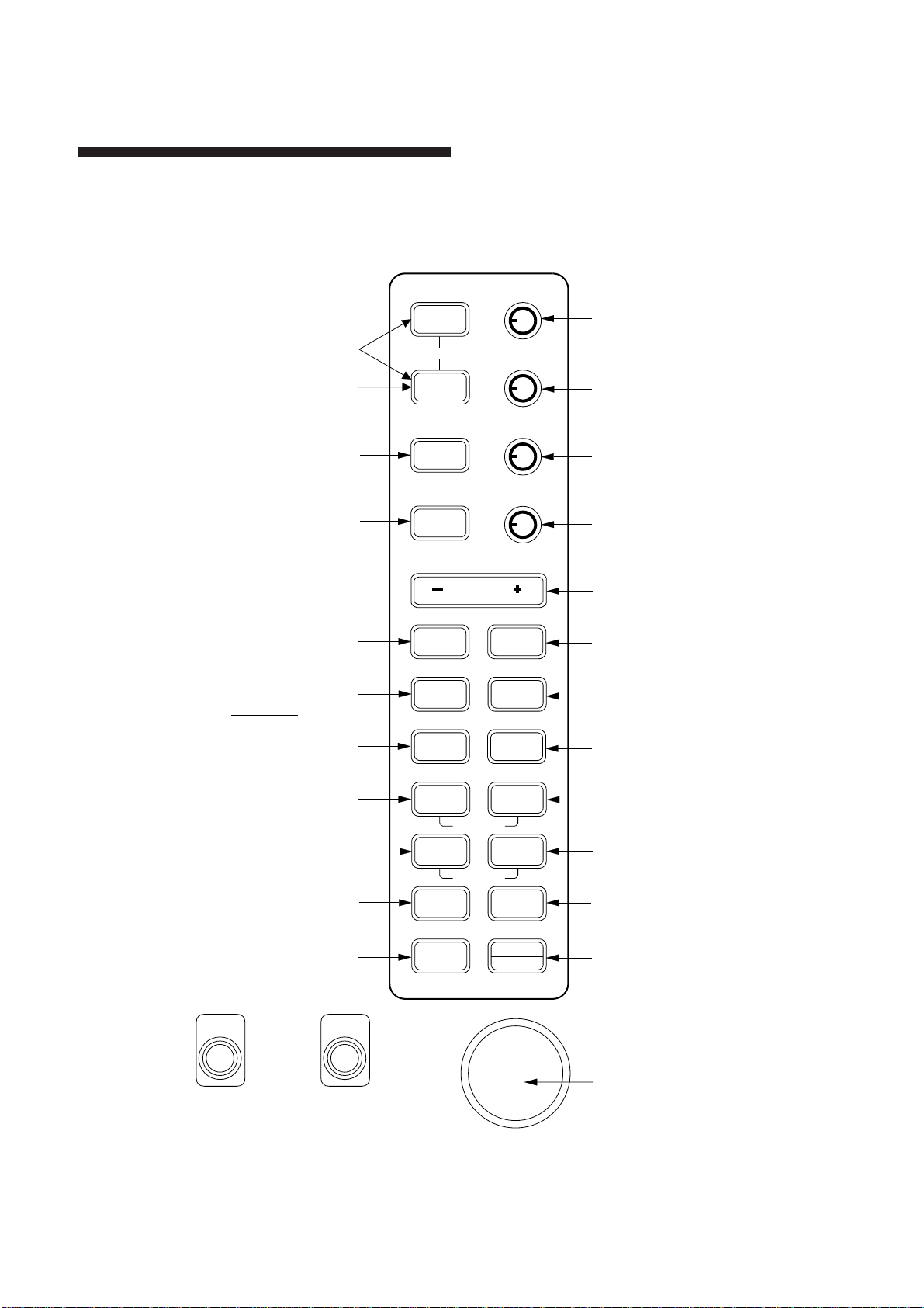
Chapter 1 OPERATION
Control Description
Turns power on.
Press together to turn
Toggles between
stand-by and display.
Presentation mode
Sets up for
required objective.
power off.
POWER
OFF
ST BY
TX
MODE
FUNCTION
GAIN
HM OFF (PUSH)
A/C SEA
A/C AUTO (PUSH)
A/C RAIN
MARK (PUSH)
BRILL
RINGS (PUSH)
GAIN: Adjusts receiver sensitivity.
Press to erase heading marker;
enable manual tuning of the receiver.
A/C SEA: Suppresses sea clutter.
Press for AUTO Anti-clutter Sea
and Rain.
A/C RAIN: Suppresses rain clutter.
Press to inscribe a reference mark (*).
BRILL: Adjusts display brilliance.
Press to turn range rings on/off
and adjust their brilliance.
alarms (except guard alarm).
Silences aural
Short press: Offcenter
Long press: Zoom-in
Each press processes index lines;
linked with EBL2/VRM2 / fixed / OFF.
Turns an EBL off.
Turns a VRM off.
Registers data on menu;
selects menu item.
Selects plotting
symbol.
EBL
VRM
(
TLL)
AUDIO
OFF
SHIFT
ZOOM
INDEX
LINE
OFF
OFF
ENTER
SELECT
PLOT
SYMBOL
RANGE
EBL 1/2
VRM 1/2
GUARD
ALARM
ECHO
TRAIL
CURSOR
OFFSET
ON
ON
MENU
CLEAR
DELETE
Selects range.
Sets/cancels guard
alarm zone; silences guard
zone alarm.
Target trails ON/OFF.
Each press processes offset EBL;
linked with cursor / fixed / OFF.
Selects EBL to activate.
Selects VRM to activate.
Opens/closes menu.
Clears wrong data; deletes
plot symbols and marks.
Rotates EBL;
selects items
on menu.
Adjusts VRM; outputs
cursor position (TL/L)
to external equipment;
selects items on
menu.
Figure 1-1 Control description
TRACKBALL
Shifts cursor and
No.1 EBL origin.
1–1
Page 12
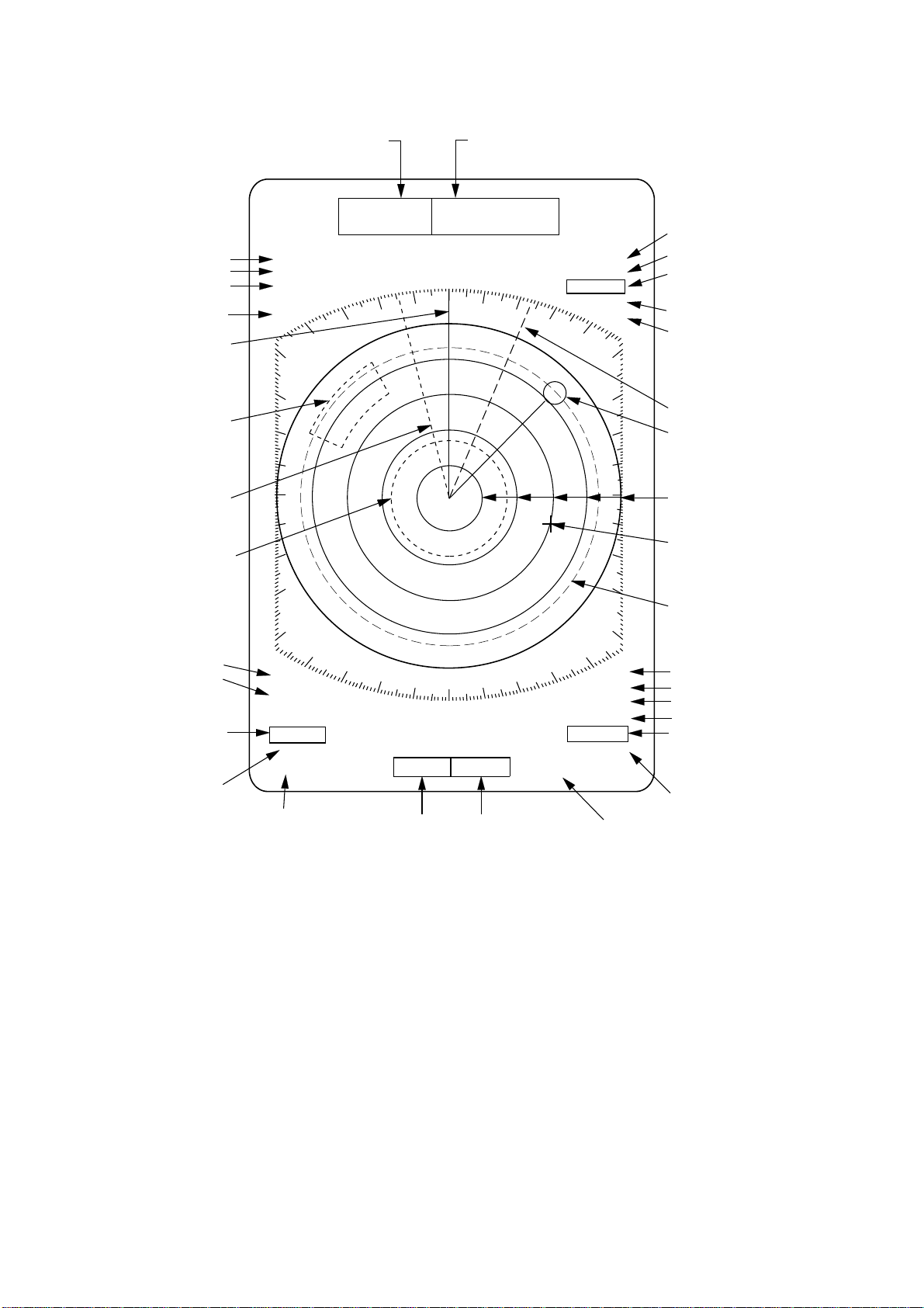
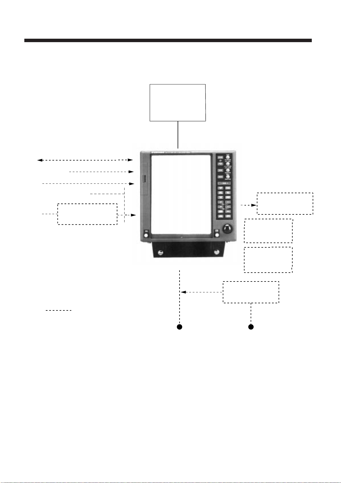
Display Indications
Range ring interval
Range
ZOOM (or SHIFT)
Presentation mode
Heading marker
Guard zone
area
No.1 EBL
No.1 VRM
Heading (gyro or
magnetic)
0.25
0.05
ZOOM
HU
NM
HDG 123.4°
Speed
(MANUAL, LOG or NAV)
SPEED
MANUAL 30.0kt
TRU TRAIL
00:45
30M
GUARD1
GUARD2
IN
Echo trail (TRU/REL)
Elapsed time, trail interval
Guard zone 1 (active alarm
is circumscribed)
Guard zone 2
IN (guard zone type), SET
(set alarm), or
ACK (alarm temporarily
deactivated)
No.2 EBL
Waypoint marker
Range rings
Cursor
Auto clutter suppression
Function in use
(F3, Long range
Echo Stretch)
No.1 EBL bearing
(readout of active EBL
is circumscribed)
No.2 EBL bearing
A/C
F3
L-ES
345.6°R
23.0°R
29:59
Watch alarm
elapsed time
EBL
+
105.0°R 00.74nm
Cursor
bearing
Cursor
range
VRM
TTG 12:34
Figure 1-2 Display indications
NR
IR2
ES1
EAV1
0.080nm
0.220nm
No.2 VRM
Noise Rejection
Interference Rejection
Echo Stretch
Echo Averaging
No.1 VRM range
(readout of active VRM is
circumscribed)
No.2 VRM range
Time-to-go
1–2
Page 13
A/C
F3
L-ES
18.0°T
290.0°R
99:99
TIME
EBL
TRUE VECTOR
30MIN
01:28
93.7°R 13.82nm
332.7°T
BRG
RNG
12.5nm
CPA
8.89nm
VRM
TTG
COURSE
SPEED
TCPA
NR
IR2
ES3
EAV1
1.829nm
10.87nm
12:34
198.5°T
92.8kt
05:11
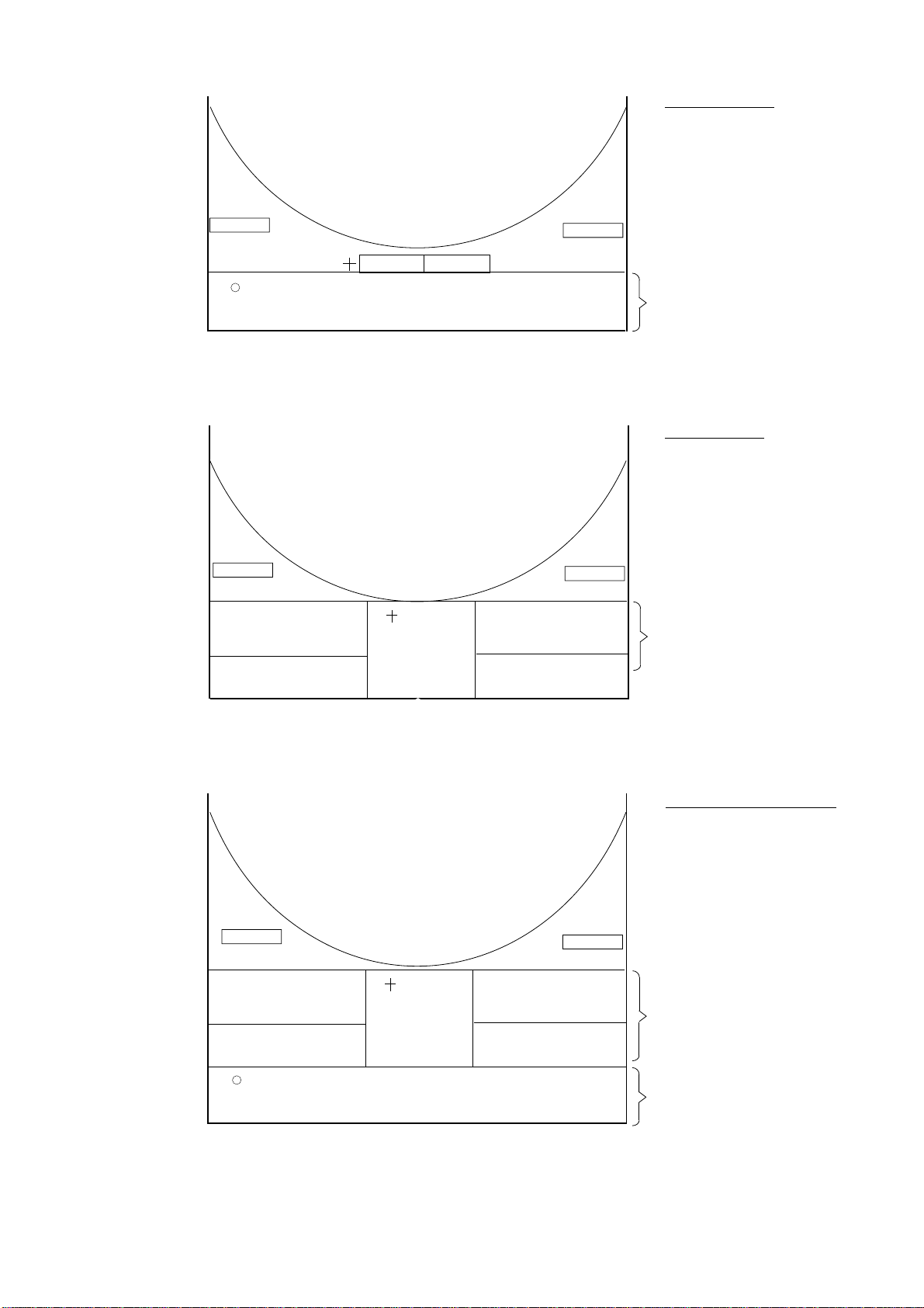
Normal + PLOT
Select PLOT on
DISP DATA menu.
PLOT Data
Normal + NAV
Select NAV on
DISP DATA menu.
.
A/C
F3
L-ES
18.0°T
290.0°R
OWN
39.46N
SHIP
135°
23.08E
COURSE
216.1°
DATE APR. 08 20:31
EBL
34°
99:99
A/C
F3
L-ES
18.0°T
290.0°R
34°
OWN
39.46N
SHIP
135°
23.08E
COURSE
216.1°
DATE APR. 08 20:31
EBL
99:99
TRUE VECTOR
30MIN
01:28
TIME
(GPS)
(GPS)
93.7°R
13.82nm
34
°39.46N
135
°23.08E
TTG
12:35
93.7°R
13.82nm
34
°39.46N
135
°23.08E
TTG
12:35
BRG
332.7°T
RNG
12.5nm
CPA
8.89nm
VRM
WAY
POINT
TTG
DEPTH
TEMP
VRM
WAY
POINT
TTG
DEPTH
TEMP
COURSE
SPEED
TCPA
NR
IR2
ES3
EAV1
1.829nm
10.87nm
321.6°
18.23nm
35:42
265.2m
23.5°C
NR
IR2
ES3
EAV1
1.829nm
10.87nm
321.6°
18.23nm
35:42
265.2m
23.5°C
198.5°T
92.8kt
05:11
NAV Data
(Requires position,
depth and water
temperature data.)
NORMAL + NAV + PLOT
Select ALL on DISP
DATA menu.
NAV Data
PLOT Data
Figure 1-3 Display indications (lower part)
1–3
Page 14
1.1 Turning the Power On/Off
1.3 Selecting Range
Turning on
Press the POWER key. The control panel lights
and a beep sounds.
Turning off
Press POWER and ST-BY/TX keys together.
1.2 Displaying Picture / Stand-by
Displaying picture
After the power is turned on, ST-BY(Stand-By)
appears at the screen center.
Press the ST-BY/TX key to display echoes. This
unit displays echoes in eight intensities according to echo strength.
Note: "BRG SIG MISSING" may momentarily
appear when the ST-BY/TX key is pressed just
after the display of ST-BY at power-up. This is
normal.
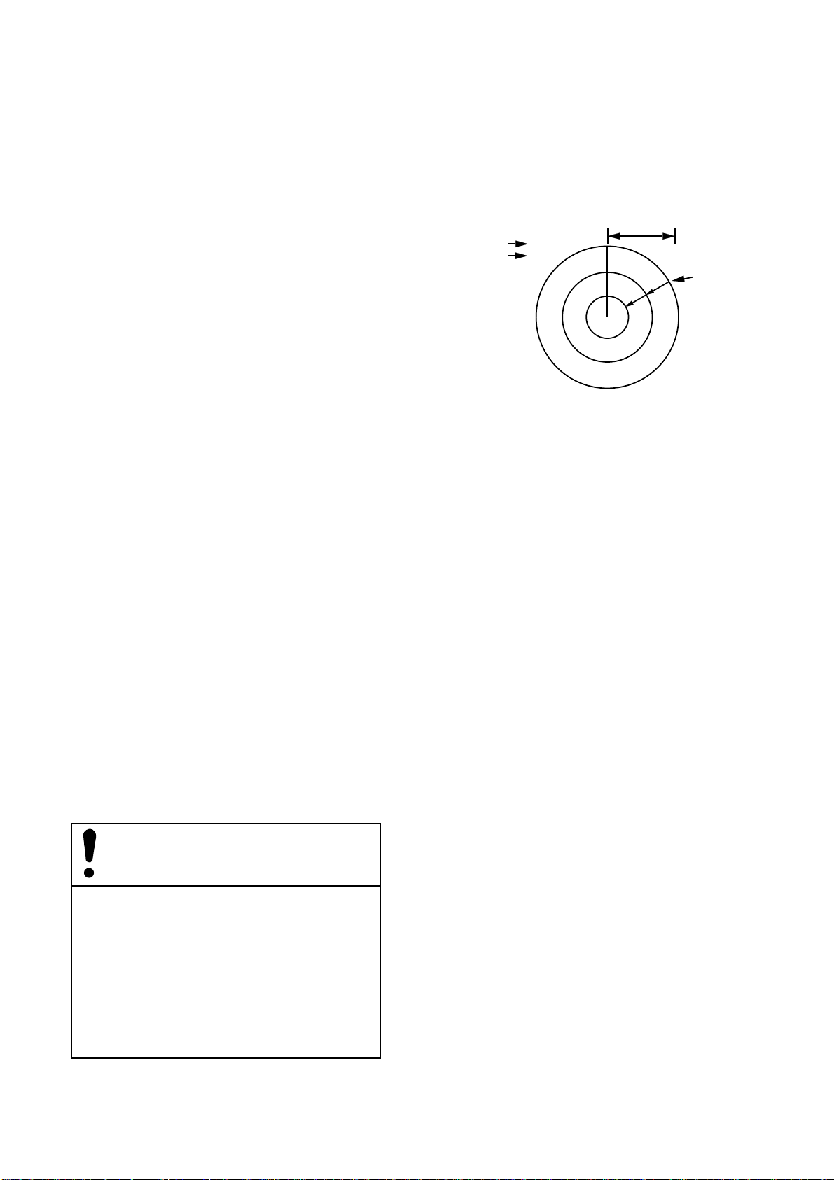
The range selected automatically determines the
range ring interval and the number of range rings,
for optimal detection capability in short to long
ranges.
Range
Range
Range ring
interval
0.75NM
0.25
Range
rings
Figure 1-4 Location of range,
range ring interval
Procedure
Press the RANGE key at + or –. The range, range
ring interval appears at the top left corner of the
display.
Stand-by
When you won’t be using the display monitor
for an extended period, but you want to keep it in
a state of readiness, place it in stand-by by pressing the ST BY/TX key . The display shows ST-BY .
Video lockup recovery
Video lockup or picture freeze, can occur unexpectedly on digital rasterscan radars. This is
mainly caused by heavy spike noise in the
power line, and can be noticed by carefully
watching the nearly invisible sweep line. If you
suspect that the picture is not updated every
scan of the antenna or no key entry is accepted
notwithstanding the apparently normal picture,
turn the power off and on.
1–4
Page 15
1.4 Presentation Mode
Loss of gyro signal
When the gyro signal is lost, the presentation
mode automatically becomes Head-up and
the HDG readout at the screen top shows
xxx.x. The x's do not disappear even when the
gyro signal is restored, to warn the operator
that the readout may be unreliable.
Match the gyro readout with the gyrocompass
reading. Press the MODE key.
This display monitor has the following presentation modes:
Relative Motion (RM)
Head-up: Unstabilized
Course-up: Compass-stabilized relative to
ship’ s intended course
North-up: Compass-stabilized with
reference to north
True Motion (TM)
Selecting presentation mode
Each time the MODE key is pressed, the presentation mode and mode indication at the upperleft corner of the screen change cyclically.
North-up: Ground or sea stabilized with
compass and speed inputs
Presentation mode,
representative display
350
320
220
330
210
340
200
190
H
E
A
D
U
310
300
290
280
P
270
260
250
240
230
000
180
010
170
020
160
030
150
040
050
060
070
080
090
100
110
120
130
140
Description
A display withouth azimuth stabilization in which the
line connecting the center with the top of the display
indicates own ship's heading.
The target pips are painted at their measured distances
and in their directions relative to own ship's heading.
The short dashed line on the bearing scale is the north
mark and it indicates compass north.
Failure of the gyro will remove the north marker and
the HDG indication shows "xxx.x".
C
O
U
R
U
350
340
330
320
310
300
290
S
280
E
270
260
P
250
240
230
220
210
200
190
180
170
020
160
030
150
000
010
040
140
130
050
120
060
070
110
080
100
090
An azimuth stabilized display in which a line connecting the center with the top of the display indicates
own ship's intended course (namely, own ship's
previous heading just before this mode has been
selected).
Target pips are painted at their measured distances
and in their directions relative to the intended course
which is maintained at the 0-degree position while the
heading marker moves in accordance with the ship's
yawing and course changes. This mode is useful to
avoid smearing of picture during course changes. After
a course change, press the SHIFT ZOOM key to reset
the picture orientation if you wish to continue using
the Course-up mode.
If the gyrocompass fails, the presentation mode changes
to the Head-up mode and the north marker disappears.
Also, the HDG readout at the screen top shows xxx.x.
1–5
Page 16

Presentation mode,
representative display
350
320
220
320
220
210
330
210
330
200
340
200
340
190
350
190
N
O
R
T
H
U
T
R
U
E
M
O
T
O
N
310
300
290
280
270
P
260
250
240
230
310
300
290
280
270
260
I
250
240
230
000
000
180
180
010
170
010
170
020
160
020
160
030
150
030
150
040
140
040
140
130
050
130
050
120
120
060
060
110
070
110
070
Description
080
090
100
080
090
100
Target pips are painted at their measured distances
and in their true (compass) directions with reference to
own ship, north being maintained at the top of the
screen. The heading marker moves according to ship's
heading.
If the gyro fails, the presentation mode changes to
the Head-up mode and the north mark disappears.
Also, the HDG readout at the screen top shows xxx.x.
Own ship and other moving objects move in accordance
with their true courses and speeds. All fixed targets,
such as landmasses, appear as stationary echoes.
When own ship reaches a point corresponding to 75% of
the radius of the radar display, the sweep origin
is automatically flipped (reset) to 50% radius opposite
to the extension of the heading marker passing
through the display center.
Sweep origin may also be reset automatically, in which
case the sweep origin is automatically reset to 50%
radius opposite on the extension of the heading marker
passing through the display center.
If the gyrocompass fails, the presentation mode is
changed to the Head-up mode and the north marker
disappears. Also, the HDG readout at the screen top
shows xxx.x.
1–6
Heading
marker
300
290
280
270
260
250
240
350
340
330
320
310
230
220
210
200
(a) True motion
is selected
North
000 010
marker
020
030
040
050
060
070
080
090
100
110
120
130
140
150
160
170180190
320
310
300
290
280
270
260
250
240
230
220
000 010
350
340
330
210
200
020
030
040
050
060
070
080
090
100
110
120
130
140
150
160
170180190
(b) Own ship has reached a
point 75% of display radius
Automatic resetting of sweep center in true motion mode
000 010
350
340
330
320
310
300
290
280
270
260
250
240
230
220
210
200
020
030
040
130
140
150
160
170180190
(c) Own ship is automatically
reset to 50% of radius
050
060
070
080
090
100
110
120
Page 17

1.5 Menu Overview
TRAIL
Sel Item by VRM & hit ENT.
TIME
CONT
MODE
TRUE
TONE
MULT
Current setting
15S
30S
1M
3M
6M
15M
30M
CONT
Options
of menu
selected
appear
here.
Cursor
The MAIN menu, composed of nine menus, contains functions which normally do not require frequent adjustment in everyday operation.
2) Operate the VRM or EBL control to select a
menu with the cursor and press the ENTER/
SELECT key. (You can also select menus by
pressing key or control shown on the MAIN
menu. In this case you need not press the ENTER/SELECT key.)
Basic menu operation
1) Press the MENU key to display the MAIN
menu.
MAIN
Sel Item by VRM & hit ENT.
TRAIL
GUARD
PLOT
ECHO
TRAIL
GUARD
ALARM
PLOT
SYMBOL
Cursor circumscribes current selection.
Figure 1-5 MAIN menu
MARK&
DATA
FUNC3
ECHO
SIG
You can select a menu by using the cursor or (in most cases) pressing appropriate
key on the control panel. To select the
PLOT menu, for example, select PLOT
and press the
press the
MARK
FUNCTION
A/C AUTO
ENTER/SELECT
PLOT SYMBOL
TIME
ALM
BRILL
INITIAL
key or
key.
AUDIO
OFF
For example, select the TRAIL menu.
Figure 1-6 TRAIL menu
3) Select option (in far right-hand column) by
operating the VRM or EBL control.
4) Press the ENTER/SELECT key to register selection.
5) Press the MENU key to close the menu.
Changing pages on the INITIAL menu
The initial menu has two pages: INITIAL1 and
INITIAL2. You can switch between them as follows:
Previous page: Place the cursor on [↑] and press
the ENTER/SELECT key.
Next page: Place the cursor on [↓] and press the
ENTER/SELECT key.
1–7
Page 18

Menu tree
TRAIL
GUARD AREA NO. (GUARD1, GUARD2)
PLOT
MARK &
DATA
TIME (15S, 30S, 1M, 3M, 6M, 15M, 30M, CONT)
MODE (REL, TRUE)
TONE (SGL, MULT)
MODE (IN, OUT)
SYMBOL
ERASE
VEC REF (REL, TRUE)
VEC TIME (30S, 1M, 3M, 6M,15M, 30M)
TRACK (OFF, ON)
MK ERASE
MK MODE (REL, TRUE)
DSP DATA (OFF, PLOT, NAV, ALL)
(
erase all plotting symbols
(
erase all fixed marks)
selection of plotting symbol
)
FUNC
ECHO SIG
FUNC SEL (S1, S2, S&M, L-ES, L-AC, ES, B1, B2)
ECHO AVG (OFF, 1, 2, 3)
INTRF (OFF, 1, 2, 3)
STRETCH (OFF, 1, 2)
A/C AUTO (OFF, ON)
N REJ (OFF, ON)
P/L SEL (P/L1, P/L2)
ECHO AVG (OFF, 1, 2, 3)
INTRF (OFF, 1, 2, 3)
STRETCH (OFF, 1, 2)
N REJ (OFF, ON)
2ND ECHO (OFF, ON)
1–8
(Continued on next page.)
Page 19

TIME ALM
TIME ALM (OFF, 3M, 6M, 12M, 15M, 20M)
TIME ALM OUT (OFF, ON)
BRILL
INITIAL
GUARD OUT (OFF, ON)
ARPA ALM OUT (OFF, ON)
PLOT ALM OUT (OFF, ON)
PANEL
TRAIL
CHAR
HDG MARK
VRM/ EBL
CURSOR
PLOT
OS MARK
SPD MODE (MAN, LOG, NAV)
Turn on/off external
output of alarms.
MAN SPD (00.0kt)
INDEX (2PCS., 6PCS.)
STERN MK (OFF, ON)
SHP GRPH (OFF, ON)
NAV DATA
AUTO TUNE PRESET
↓
↑
NAV SEL (OFF, ALL, GPS, LC, DR, DEC)
EXT WP (OFF, ON)
OS POSN (L/L, TD) TD = Time Difference
DEPTH (m, FA, ft)
TEMP (°C,° F)
DATE (OFF, ON)
↑
CRSR BRG (REL, TRUE)
CRSR RNG (nm, km, sm)
VRM1 RNG (nm, km, sm)
VRM2 RNG (nm, km, sm)
EBL1 BRG (REL, TRUE)
EBL2 BRG (REL, TRUE)
TEST
INSTALL (for service technicians)
1–9
Page 20

1.6 Adjusting Sensitivity
BRILL1
The GAIN control adjusts the sensitivity of the
receiver and thus the intensity of echoes as they
appear on the screen.
The proper setting is such that the background
noise is just visible on the screen. If you set up
for too little sensitivity, weak echoes may be
missed. On the other hand excessive sensitivity
yields too much background noise; strong targets
may be missed because of the poor contrast between desired echoes and the background noise
on the display.
To adjust receiver sensitivity, transmit on long
range, and adjust the GAIN control so background
noise is just visible on the screen.
1.7 Adjusting Picture Brilliance
The BRILL control adjusts the brilliance of the
picture.
Sel Item by VRM & hit ENT.
PANEL
TRAIL
CHAR
Setting
HDG MARK
VRM/EBL
CURSOR
PLOT
OS MARK
Current
level
Figure 1-7 BRILL menu
4) Select appropriate menu among the following
and press the ENTER/SELECT key.
PANEL, TRAIL, CHAR, HDG MARK,
VRM/EBL, CURSOR, PLOT, OS MARK
5) Operate the VRM or EBL control to set brilliance.
6) Press the ENTER/SELECT key.
7) Press the MENU key.
1.8 Adjusting Brilliance of Control Panel and Markers
The brilliance of the control panel and markers
can be adjusted on the BRILL menu. The heading marker is visible when set to zero.
1) Press the MENU key.
2) Select the BRILL menu.
3) Press the ENTER/SELECT key.
1.9 Adjusting Range Ring
Brilliance
Push in the RINGS (PUSH) control to adjust
range ring brilliance/turn the range rings on or
off. Each pressing of the key adjusts the brilliance
of the rings (in four levels) or turns them off.
1–10
Page 21

1.10 Suppressing Sea Clutter
In rough weather conditions returns from the sea
surface are received over several miles around
own ship and mask nearby targets. This situation
can be improved by properly using the automatic
anti-clutter function and/or the A/C SEA control.
Automatic anti-clutter control
The easiest way to suppress the surface clutter is
to use the automatic anti-clutter function. Press
the A/C AUTO switch.
A common mistake is too over-adjust the A/C
SEA control so that the surface clutter is completely removed. By rotating the control fully
clockwise, you will see how dangerous this can
be; a dark zone will be created near the center of
the screen, causing a loss of close-in targets. This
dark zone is even more dangerous if the gain has
not been properly adjusted. Always leave a little
surface clutter visible on the screen. If no clutter
is observed (on very calm waters), set the control
at the fully counterclockwise position.
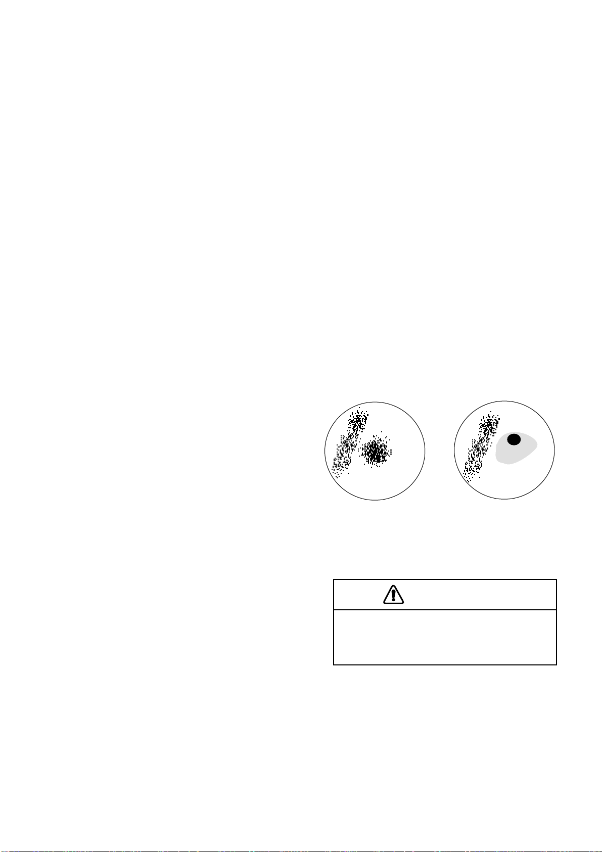
1.11 Suppressing Rain Clutter
CAUTION
The auto A/C function can erase weak
targets.
Manual anti-clutter control
From the fully counterclockwise position, slowly
turn the A/C SEA control clockwise. For optimum target detection, leaves speckles of the surface return slightly visible.
Sea clutter at
display center
A/C SEA control adjusted;
sea clutter suppressed
In adverse weather conditions, clouds, rain or
snow produce a lot of spray-like spurious echoes
and impairs target detection over a long distance.
This situation can be improved by using a Function key that is so programmed. If the Function
key fails to effectively suppress rain clutter, use
the A/C RAIN control.
The A/C RAIN control adjusts the monitor sensitivity as the A/C SEA control does but rather in
a longer time period (longer range). Clockwise
rotation of this control increases the anti-clutter
effect.
Appearance of rain
clutter on the display
A/C RAIN control adjusted;
rain clutter suppressed
Figure 1-8 Effect of A/C SEA control
The anti-clutter sea facility is often referred to as
STC (Sensitivity Time Control), which decreases
the sensitivity, and progressively increases the
sensitivity as the range increases.
If the control is set too low, tar gets will be hidden
in the clutter, while if it is set too high, both sea
clutter and targets will disappear from the display. In most cases adjust the control until clutter
has disappeared to leeward, but a little is still visible windward.
Figure 1-9 Effect of A/C RAIN control
1–11
Page 22

1.12 The Heading and North Markers
The heading marker indicates the ship's heading
in all presentation modes. It appears at zero degrees on the bearing scale in the Head-up mode,
in any direction depending on the ship orientation in North-up and True Motion modes. The
north marker appears as a short dashed line. In
the Head-up mode, the north marker moves
around the bearing scale in accordance with the
compass signal.
T o temporarily extinguish the heading marker to
look at targets existing dead ahead of own ship,
press the HM OFF (PUSH) control. The heading
marker reappears when the key is released.
VRM
5.03nm
12.5nm
No.1 VRM
No.2 VRM
Figure 1-10 Location of VRM readouts
2) Operate the VRM control to place the outside
edge of the VRM on the inside edge of the
target.
3) Check the VRM readout at the bottom right
corner of the display to find the range to the
target.
6.0NM
1.0
No.1 VRM
Target
1.13 Measuring the Range
There are three ways to measure the range to a
target: by the range rings, by the cursor and by
the VRM (Variable Range Marker).
Measuring range by the range rings
Use the range rings to obtain a rough estimate of
the range to a target. They are concentric circles
around own ship, or the sweep origin. The number of rings is automatically determined by the
selected range scale and their interval is displayed
at the upper-left position of the screen. Press the
RINGS (PUSH) control to show the range rings
if they are not displayed. Successive presses of
the RINGS (PUSH) control gradually increase
the brightness of the rings in four steps and a fifth
press erases the rings.
No.2 VRM
VRM
5.0nm
4.0nm
No.1 VRM range
No.2 VRM range
Figure 1-11 How to measure range by VRM
Erasing VRMs
1) If two VRMs are displayed, press the VRM
ON key to circumscribe the VRM readout of
the VRM you want to keep active.
2) Press the VRM OFF key. The VRM readout
and its associated VRM are erased.
Note: You can select unit of range measurement
for the cursor and VRM on the INITIAL menu.
For further details see 1.35 Selecting Unit of
Range Measurement, Bearing Reference.
Measuring range by the cursor
Rotate the trackball to place the cursor on the inside edge of the target. The range to the cursor
appears at the bottom of the display.
Measuring range by VRM
1) Press the VRM ON key to enable a VRM. Each
pressing of the key enables the No.1 VRM or
No.2 VRM alternately. The active marker’s
readout is circumscribed.
1–12
Page 23

1.14 Measuring Bearing
Measuring bearing by cursor
1.15 Collision Assessment by the Offset EBL
Rotate the trackball to set the cursor intersection
on the center of the target. The bearing to the cursor intersection appears at the bottom of the display.
Measuring bearing by EBL
1) Press the EBL ON key to enable an EBL. Each
pressing of the key enables the No.1 EBL or
No.2 EBL alternately. The active marker’s
readout is circumscribed.
2) Operate the EBL control to bisect the target
with the EBL.
3) Check the EBL readout at the bottom left corner of the display.
No.1
EBL
Target
The origin of the No.1 EBL can be placed anywhere with the trackball to assess the risk of collision, as well as to measure the range and bearing
between two targets.
1) Press the EBL ON key to turn on (or activate)
the No.1 EBL.
2) Press the CURSOR OFFSET key.
3) Operate the trackball to place the No.1 EBL
origin on the target.
4) Operate the EBL control to pass the No.1 EBL
through the screen center.
You can anchor the EBL, to continue monitoring
target’ s track, by pressing the CURSOR OFFSET
key again. If the target tracks along the No.1 EBL
toward the screen center, the possibility of collision exists.
No.1 EBL bearing
No.2 EBL bearing
50.0°R
80.0°R
EBL
No.2
EBL
Figure 1-12 How to measure bearing by EBL
Note 1: You can display EBL bearing relative to
own ship (relative) or with reference to the north
(True). For further details see 1.35 Selecting Unit
of Range Measurement, Bearing Reference.
Note 2: Suffix "T" denotes true bearing (for gy-
rocompass input) and suffix "M" denotes magnetic bearing (magnetic compass input).
Erasing EBLs
1) If two EBLs are displayed, press the EBL ON
key to circumscribe the EBL readout of the
EBL you want to keep active.
No.1 EBL
Target
(initial position)
70.0°R
No.1
EBL bearing
EBL
Figure 1-13 How to assess risk of collision
2) Press the EBL OFF key. The EBL readout and
its associated EBL are erased.
1–13
Page 24

Canceling the cursor offset
Press the CURSOR OFFSET key to return the
No.1 EBL origin to the screen center . (Each pressing of the key links the offset EBL with the cursor, anchors the of fset EBL, or returns No.1 EBL
origin to the screen center.)
1.16 Measuring Range and
1.17 Index Lines
The index lines are useful for maintaining a constant distance between own ship and a coastline
or partner ship. They can be turned on/off by the
INDEX LINE key . Each pressing of the key turns
on the index lines (linked with No.2 EBL and
No.2 VRM), anchors the index lines, or turns off
the index lines.
Bearing Between Two T argets
The range and bearing between two targets, for
example, targets A and B in Figure 1-14, can be
measured by using the CURSOR OFFSET key.
1) Press the EBL ON key to turn on (or activate)
the No.1 EBL.
2) Press the CURSOR OFFSET key.
3) Operate the trackball to place the No.1 EBL
origin on target A.
4) Operate the EBL control to pass the No.1 EBL
through target B.
5) Press the VRM ON key to turn on (or activate) the No.1 VRM.
6) Operate the VRM control to place the No.1
VRM on the inside edge of target B.
Range and bearing between the two targets appear in the cursor data window at the bottom of
the display.
No.2 EBL
Index
lines
Figure 1-15 Index lines
Rotating the index lines
Activate the No.2 EBL and operate the EBL control.
Adjusting index lines intervals
Activate the No.2 VRM and operate the VRM
control.
1–14
No.1 EBL
B
A
70.0°R
No.1 EBL No.1 VRM
bearing range
EBL VRM
No.1 VRM
4.5NM
Figure 1-14 Measuring range and
bearing between two targets
Selecting number of index lines
The number of index lines can be selected to two
or six on the INITIAL menu.
1) Press the MENU key.
2) Select the INITIAL menu and press the ENTER/SELECT key.
3) Select INDEX and press the ENTER/SELECT
key .
4) Select 2PCS (or 6PCS).
5) Press the ENTER/SELECT key.
6) Press the MENU key.
Page 25

1.18 Off-centering the Picture
Your vessel’s position can be off-centered up to
75% of the range in use to view the situation
around your vessel without changing the range
or size of targets.
1) Operate the trackball to set cursor where desired.
2) Press the SHIFT ZOOM key. SHIFT appears
at the top left corner of the display.
+
+
Cursor
Cursor
1 Place cursor
where desired.
2 Press SHIFT
ZOOM key to zoom.
Figure 1-17 Zoom function
Note: Zoom is canceled when range or presenta-
tion mode is changed.
Canceling zoom
Cursor
1 Set cursor
where desired.
Cursor
2 Press SHIFT ZOOM
key to shift display.
Figure 1-16 Off-centering the picture
Note: The display cannot be off-centered on the
96 nm range. In True Motion, the SHIFT ZOOM
key resets the OS position to a point of 50% radius opposite to the extension of the heading
marker passing through the display center.
Canceling off-centered picture
Press the SHIFT ZOOM key again.
1.19 Zoom
The zoom feature allows you to double the size
of the area between your vessel and any location
within the current range to take a closer look at
an area of interest.
1) Select location with the cursor.
Press the SHIFT ZOOM key again.
1.20 Inscribing Marks on the Display
The MARK (PUSH) control inscribes marks on
the display. Each time the MARK (PUSH) control is pressed, an asterisk (*) appears at the cursor location. You can inscribe 20 marks on the
display to denote important locations such as
wrecks and fishing grounds, or mark radar targets when changing the range. When the memory
for marks becomes full, the eldest mark is erased
to make room for the latest.
Inscribing marks
Place the cursor on the location desired for a mark
and press the MARK (PUSH) control.
Erasing marks
2) Press and hold down the SHIFT ZOOM key
about two seconds. ZOOM appears at the top
left corner when the zoom function is on.
Erasing individual marks
Place the cursor on the mark to erase and press
the CLEAR/DELETE key.
1–15
Page 26

Erasing all marks
Table 1-1 Eight available target objectives
1) Press the MENU key.
2) Select the MARK & DATA menu and press
the ENTER/SELECT key.
3) Select MK ERASE.
4) Press the ENTER/SELECT key.
5) Press the MENU key.
Mark bearing reference
You can display a mark with a relative bearing to
own ship (relative) or with reference to the north
(True).
1) Press the MENU key.
2) Select the MARK & DATA menu and press
the ENTER/SELECT key.
3) Select MODE and press the ENTER/SELECT
key .
4) Select REL (or TRUE).
5) Press the ENTER/SELECT key.
6) Press the MENU key.
evitcejbOnoitpircseD
1S
)1egnartrohS(
.aerarobrahni
2S
)2egnartrohS(
M&S
dnatrohS(
)segnarmuideM
SE-L
-egnargnoL(
)hctertSohcE
CA-L
-egnargnoL(
)rettulc-itna
SE
)hctertSohcE(
.segnar
)1youB(1Bvan(stegratllamstcetedoT
.mn
)2youB(2BnostegratllamstcetedoT
.mn21nihtiw
.hctertS
noitagivanegnartrohS
,elpmaxerof;)mn5.1nihtiw(
noitagivanegnartrohS
,elpmaxerof,mn3nihtiw
.hcaorpparobrah
segnarnonoitagivanlatsaoC
6ot5.1notegratecnahneoT
ohcEgnisuybegnarmn
3norettulcaessserppusoT
.segnarrehgihdnaegnarmn
noseohcetegratyfingamoT
rehgihdnaegnarmn5.1
,staolf,slessevllams,syoub
5.1nihtiwsegnarno).cte
.mn5.1nahtretaergsegnar
1.21 The FUNCTION key
The FUNCTION key works similar to the automatic dialing feature on a telephone, playing back
controls settings just as they were registered. Instead of manually adjusting controls to set up for
navigation in a harbor, for example, you can have
the FUNCTION key do it for you.
Presetting the FUNCTION key
Eight target objectives are available and you can
assign three sets on the FUNC menu. The eight
objectives available are outlined in the table which
follows.
Procedure
1) Press the FUNCTION key to display function
number to program (F1, F2, or F3).
2) Press the MENU key and select the FUNC
menu.
3) Press the ENTER/SELECT key.
FUNC
FUNC SEL (S1, S2, S&M, L-ES, L-AC, ES, B1, B2)
ECHO AVG (OFF, 1, 2, 3)
INTRF (OFF, 1, 2, 3)
STRETCH (OFF, 1, 2)
A/C AUTO (OFF, ON)
N REJ (OFF, ON)
P/L SET
0.75~1.5NM: SP, M1P
3NM: SP, M1P, M2P
6NM: M1P, M2P, LP
12~24NM: M2P, LP
1–16
Figure 1-18 FUNC menu
Page 27

5) Select FUNC SEL and press the ENTER/SELECT key .
6) Select target objective desired and press the
ENTER/SELECT key.
7) Press the MENU key.
Note: Each target objective defines a combina-
tion of several radar settings for achieving optimum setup for that particular objective.
Therefore, adjustment of radar settings through
the FUNC menu is not necessary. If you accidentally change the settings, default settings can
be restored by reselecting the target objective.
Turning on a function
Manual speed input
1) Press the MENU key.
2) Select the INITIAL menu and press the ENTER/SELECT key.
3) Select SPD MODE and press the ENTER/
SELECT key.
4) Select MANU.
5) Press the ENTER/SELECT key.
6) Enter speed and press the ENTER/SELECT
key.
7) Press the MENU key.
Press the FUNCTION key to display function
number desired (at bottom left corner on the display.)
Note: When the main menu displays FUNC
KEY*, this means no function is active and the
FUNCTION key is inoperative. To select a function, erase the menu and press the FUNCTION
key.
1.22 Own Ship Speed
Ship’s speed can be entered manually or automatically (by speed log or radionav equipment).
Own ship's speed is required for TM and display
of vectors, E-plot, etc. The True Motion display
works on a ship speed entered manually or automatically .
1.23 Ship’s Graphic
A graphic ( ) which depicts own ship can be
displayed.
1) Press the MENU key.
2) Select the INITIAL menu.
3) Press the ENTER/SELECT key.
4) Select SHP GRPH and press the ENTER/SELECT key .
5) Select ON (or OFF).
6) Press the ENTER/SELECT key.
7) Press the MENU key.
1.24 Interference Rejector
Automatic speed input
1) Press the MENU key and select the INITIAL
menu.
2) Press the ENTER/SELECT key.
3) Select SPD MODE and press the ENTER/
SELECT key.
4) Select LOG or NAV and press the ENTER/
SELECT key.
6) Press the MENU key.
Note: If no speed is input for 3 minutes at below
0.1 knots, the radar regards this a log failure and
displays SYSTEM FAIL LOG.
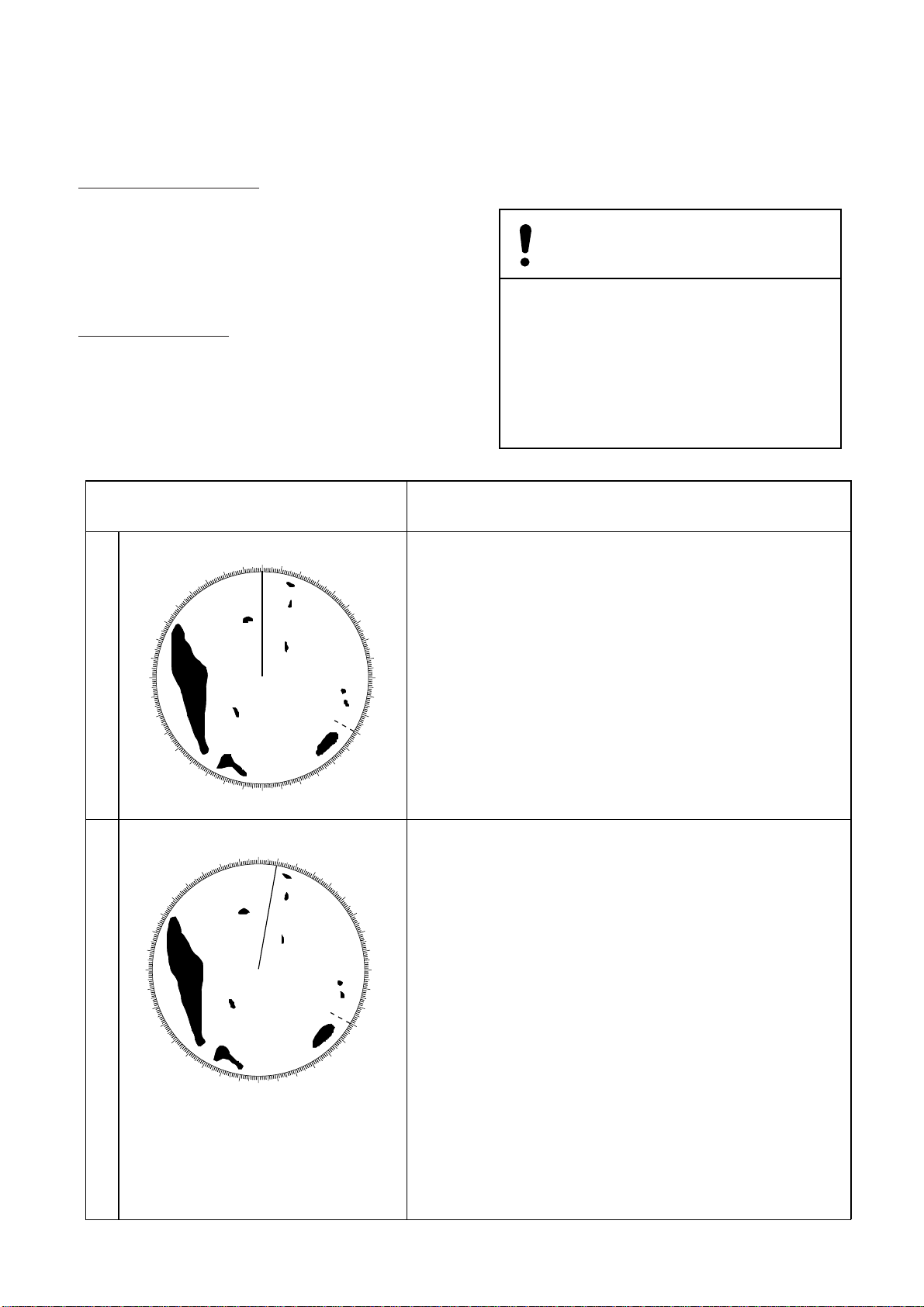
Mutual radar interference may occur in the vicinity of another shipborne radar operating in the
same frequency band (9 GHz). It is seen on the
screen as a number of bright spikes either in irregular patterns or in the form of usually curved
spoke-like dotted lines extending from the center to the edge of the picture. This type of interference can be reduced by activating the
interference rejector circuit.
1–17
Page 28

The interference rejector circuit is a kind of signal correlation circuit. It compares the received
signals over successive transmissions and suppresses randomly occurring signals. There are
three levels of interference rejection depending
on the number of transmissions that are correlated. These are indicated by the legends IR1, IR2
and IR3 at the bottom right-hand position of the
screen.
T o turn on or of f the interference rejector circuit;
1) Press the MENU key.
2) Select ECHO SIG and press the ENTER/SELECT key.
True motion trails require a gyrocompass signal
and own ship speed input to cancel out own ship's
movement and present true target movements in
accordance with their over-the-ground speeds and
courses (not heading). Refer to the automatic and
manual speed input procedures for entering own
ship's speed information.
3) Select INTRF and press the ENTER/SELECT
key .
4) Select level of suppression desired (higher the
number the greater the suppression) and press
the ENTER/SELECT key.
5) Press the MENU key.
Figure 1-19 Radar interference
1.25 Echo Trails
True trails Relative trails
Figure 1-20 True and relative echo trails
Note: If the true trail is selected on the stabilized
RM (CU, NU), targets whose extensions hit own
ship are not always on a collision course.
Starting echo trail
Press the ECHO TRAIL key to start the echo trail
function. “REL (or TRU) TRAIL”, the echo trail
time selected (on the TRAIL menu) and elapsed
time appear at the top right-hand corner of the
display . Then, afterglow starts extending from all
targets.
Canceling echo trail
Press the ECHO TRAIL key to erase echo trails
and echo trail indications.
Echo trails are simulated afterglow of target echoes that represent their movements relative to own
ship or true movements with respect to land, in a
single tone or gradual shading depending on the
setting on the TRAIL menu.
True or relative trails
You may display echo trails in true or relative
motion. Relative trails show relative movements
between targets and own ship. In the true motion, the moving targets have trails according to
their speeds, but stationary targets stay still.
1–18
Trail time
Trail time can be selected on the TRAIL menu.
1) Press the MENU key.
2) Select the TRAIL menu.
3) Press the ENTER/SELECT key.
4) Select TIME and press the ENTER/SELECT
key.
5) Select trail time among 15 seconds, 30 seconds, 1, 3, 6, 15, 30 min, or continuous (99
minutes 59 seconds).
Page 29

6) Press the ENTER/SELECT key.
2) Select the BRILL menu.
7) Press the MENU key.
Trail reference
Echo trails can be displayed relative to own ship
(relative) or with reference to north (true).
1) Press the MENU key.
2) Select the TRAIL menu.
3) Press the ENTER/SELECT key.
4) Select MODE and press the ENTER/SELECT
key .
5) Select trail reference; true or relative.
6) Press the ENTER/SELECT key.
7) Press the MENU key.
Trail gradation
Echo trails may be shown in monotone or gradual
shading (multiple). Gradual shading paints the
trails getting thinner with time just like the afterglow on an analog PPI radar.
Monotone trail
Multitone trail
Figure 1-21 Comparison of
trail gradation types
3) Press the ENTER/SELECT key.
4) Select TRAIL and press the ENTER/SELECT
key .
5) Operate the VRM or EBL control to adjust trail
brilliance.
6) Press the ENTER/SELECT key.
7) Press the MENU key.
1.26 Electronic Plotting (E-plot)
10 operator-selected targets can be plotted electronically to assess their motion trends. Five past
positions are marked for each plotted target.
A vector appears as you enter a second plot for a
target and is updated each time a new plot is entered for the target. The vector shows the target
motion trend based on its latest two plots.
Alphanumeric readouts for last-plotted or selected
target appear at the bottom of the display.
It should be noted that the vector and alphanumeric target data are not updated in real time, but
only when you enter a new plot.
E-plot requires ship's speed input (automatic or
manual) and a compass signal.
1) Press the MENU key.
2) Select the TRAIL menu.
3) Press the ENTER/SELECT key.
4) Select TONE and press the ENTER/SELECT
key .
5) Select SGL or MULT.
6) Press the ENTER/SELECT key.
7) Press the MENU key.
Trail brilliance
Trail brilliance may be adjusted on the BRILL
menu.
1) Press the MENU key.
When speed is input by a navigator, own ship
moves in accordance with course; not heading.
Plotting a target
Before plotting a target, select PLOT or ALL on
the MARK & DATA DSP menu.
1) Place the cursor on the target you want to plot,
and press the PLOT SYMBOL key.
2) Watching the E-plot timer on the PLOT mode,
wait at least 30 seconds. Place the cursor on
the plot symbol and press the ENTER/SELECT key. The plot symbol of the target
flashes.
3) While the plot symbol of the target is flash-
ing, place the cursor on the target again and
press the PLOT SYMBOL key. The plot symbol shifts to the new target position and the
previous position is marked by a small dot.
1–19
Page 30

Target data
0.25
0.05
ZOOM
SP
HU
Vector
A/C
F3
L-ES
345.6°R
23.0°R
TIME
HDG 123.4°
NM
EBL
REL VECTOR
12MIN
01:28
SPEED
MANUAL 30.0kt
+
105.0°R 00.74nm
057.1°R
BRG
2.7nm
RNG
0.4nm
CPA
AUTO
Plot
symbol
VRM
TTG
COURSE
SPEED
TCPA
GUARD1
GUARD2
Past
position
(max. 5)
0.080nm
0.220nm
12:34
231.0°R
7.5kt
22.2
IN
NR
IR2
ES1
EAV1
Place the cursor on the plotted target and press
the ENTER/SELECT key . Vector reference, vector time, vector time elapsed, and selected target’ s
bearing, course, speed, CPA and TCPA appear at
bottom of the display.
In the head-up mode target bearing course and
speed become true or relative depending on vector reference setting. In north-up, course-up and
true motion the target data always shows true
bearing, true course and speed over the ground.
True or relative vector
Target vectors can be displayed relative to own
ship (relative) or with reference to the north
(True). Current vector reference appears at the
bottom of the display when the PLOT mode is
active.
1) Press the MENU key.
2) Select the PLOT menu.
3) Press the ENTER/SELECT key.
4) Select VEC REF and press the ENTER/SELECT key .
Plot data (for )
Figure 1-22 Plotting
Note: If a certain target once plotted is not plot-
ted again within 12 minutes, the plot symbol of
the target flashes. If you want to continue plotting this target, reacquire it within one minute,
otherwise the target will be regarded as a “lost
target” and its plot symbol and target data will be
erased. The larger the plotting interval, the less
accurate the plotted target data. Plotting of each
target should normally be made every 3 or 6 minutes as far as possible.
5) Select vector reference.
6) Press the ENTER/SELECT key.
7) Press the MENU key.
Vector time
A vector extends from plotted targets to show
projected position of target at elapse of vector
time. The vector is useful for evaluating risk of
collision. Current vector time appears at the bottom of the display when the PLOT mode is active.
1) Press the MENU key.
2) Select the PLOT menu.
3) Press the ENTER/SELECT key.
4) Select VEC TIME and press the ENTER/SELECT key .
5) Select vector time.
1–20
6) Press the ENTER/SELECT key.
7) Press the MENU key.
Page 31

Turning past position display on/off
1.27 Setting a Guard Alarm
The plots the latest five past positions of a plotted target by dots. You can show or hide the dots.
1) Press the MENU key.
2) Select the PLOT menu.
3) Press the ENTER/SELECT key.
4) Select TRACK and press the ENTER/SELECT key .
5) Select ON (or OFF).
6) Press the ENTER/SELECT key.
7) Press the MENU key.
Canceling target plotting
Canceling individual target plotting
Place the cursor on the plot symbol and press the
CLEAR/DELETE key.
Zone
The guard allows the operator to set the desired
range and bearing for a guard zone. When ships,
islands, landmasses, etc. violate the guard zone
an aural alarm sounds and the offending target
blinks to call the operator’s attention. Two areas
can be set, zone 1 (short dashed line) and zone 2
(long dashed line), and one may be active.
CAUTION
• The alarm should not be relied upon as
the sole means for detecting possible
collision situations.
• A/C SEA, A/C RAIN and GAIN controls
should be properly adjusted to be sure the
alarm system does not overlook target
echoes.
Canceling all target plotting
1) Press the MENU key.
2) Select the PLOT menu.
3) Press the ENTER/SELECT key.
4) Select ERASE and press the ENTER/SELECT
key .
5) Press the MENU key.
Selecting guard zone type
The guard alarm can be set to sound when a target either enters (or exits) the guard zone. You
can select which type of guard alarm you want to
use through the GUARD menu.
In alarm: The alarm sounds on targets entering
the guard zone. (IN) appears at the top right-hand
corner when the In alarm is selected.
Out alarm: The alarm sounds on targets exiting
the guard zone. (OUT) appears at the top
right-hand corner when the Out alarm is selected.
Dashed line:
no alarm
Guard
zone
IN ALARM OUT ALARM
Figure 1-23 In and out alarms
1–21
Page 32

1) Press the MENU key.
2) Select the GUARD menu.
3) Press the ENTER/SELECT key.
4) Select MODE and press the ENTER/SELECT
key .
5) Select IN (or OUT).
6) Press the ENTER/SELECT key.
7) Press the MENU key.
Activating the guard zones
T wo guard zones may be set and one of them may
be active. Select the guard zone to make active
on the GUARD menu.
Guard zone
to set
A
B
(1)
GUARD1
IN
(4)
Guard zone
A
D
C
Set cursor
on point A
(or B) and
press GUARD
ALARM.
(or OUT)
Press
GUARD
ALARM.
(or GUARD2)
GUARD1
SET
(2)
(or GUARD2)(or GUARD2)
GUARD1
SET
Set cursor
on point C
(or D).
(3)
1) Press the MENU key.
2) Select the GUARD menu.
3) Press the ENTER/SELECT key.
4) Select AREA NO. and press the ENTER/SELECT key.
5) Select guard zone to make active; GUARD1
(or GUARD2).
6) Press the ENTER/SELECT key.
7) Press the MENU key.
Setting a guard zone
1) Referring to (1) in Figure 1-24, operate the
trackball to place the cursor at point A or B.
2) Press the GUARD ALARM key . GUARD1 (or
GUARD2) SET appears at the top right corner on the display. See Figure 1-24 (2).
3) Operate the trackball to place the cursor at
point C or D. See Figure 1-24 (3). GUARD1
(or GUARD2) IN (or OUT) appears.
4) Press the GUARD ALARM key.
Figure 1-24 How to set the guard alarm
Note: When the radar range is less than one half
of the guard zone range, the guard zone disappears and the indication of active guard zone
(GUARD1 or GUARD2) appears in highlighted
video. If this happens, raise the range to re-display
the guard zone.
Silencing the aural alarm
When a target violates the guard zone, the target
flashes and the aural alarm sounds. You can silence the aural alarm by pressing the GUARD
ALARM key. When this is done, ACK replaces
IN (or OUT). This means the aural alarm is temporarily deactivated; but, the target still flashes.
Press the key again to reactivate the alarm.
Canceling the guard zone and guard
alarm
Press and hold down the GUARD ALARM key
about two seconds until the guard zone disappears.
1–22
Page 33
1.28 Watch Alarm
The watch alarm works like an alarm clock,
sounding an aural alarm and blinking a visual
indication “T ALM” at the predetermined time
interval. When the alarm sounds, you can silence
it by pressing the AUDIO OFF key.
How to turn on echo averaging
To properly use the echo average feature, first
properly suppress sea clutter with the A/C SEA
control and then select echo average function as
follows;
1) Press the MENU key.
You can select time interval (3 min, 6 min, 12
min, 15 min, or 20 min) on the TIME ALM menu.
1) Press the MENU key.
2) Select the TIME ALM menu.
3) Press the ENTER/SELECT key.
4) Select TIME ALM and press the ENTER/SELECT key .
5) Select time interval (or OFF).
6) Press the ENTER/SELECT key.
7) Press the MENU key.
1.29 Echo Average
The echo average feature effectively suppresses
sea clutter and other random noise. Echoes received from stable targets such as ships (if not
moving at high speeds) appear on the screen at
almost the same position every rotation of the
antenna. On the other hand, unstable echoes such
as sea clutter appear at random positions.
2) Select the ECHO SIG menu.
3) Press the ENTER/SELECT key.
4) Select ECHO AVG and press the ENTER/SELECT key .
5) Select 1, 2, or 3.
1: Distinguishes targets from sea clutter and
suppresses brilliance of unstable echoes.
2: Distinguishes small stationary targets such
as navigation buoys.
3: Displays distant targets as stable echoes.
6) Press the ENTER/SELECT key.
7) Press the MENU key.
a) Echo average OFF b) Echo average 1
To distinguish real tar get echoes from sea clutter,
this radar performs scan-to-scan correlation. Correlation is made by storing and averaging echo
signals over successive picture frames. If an echo
is solid and stable, it is shown in its normal intensity. Sea clutter is averaged over successive
scans and reduced in brightness. This makes it
easier to discriminate real targets from sea clutter.
Figure 1-25 Echo average
CAUTION
Do not use the Echo Average feature under
heavy pitching or rolling; loss of true
targets can result.
1–23
Page 34

Echo averaging uses scan-to-scan signal correla-
r
tion technique based on the true motion over the
ground of each target. Thus, small stationary tar gets such as buoys will be shown while suppressing random echoes such as sea clutter . T rue echo
average is not however effective for picking up
small targets running at high speeds over the
ground.
The echo average feature is inoperable when a
heading signal is not available. If you wish to use
this feature without a heading signal, system initialization is required. (Consult a FURUNO representative or dealer.)
Note: Echo averaging also requires ship's speed
information from a log or manual entry.
1.31 Echo Stretch
On long ranges target echoes tend to shrink in
the bearing direction, making them difficult to
see. On short and medium ranges such as 1.5, 3
and 6 nm range scales, the same sized targets get
smaller on screen as they approach own ship.
These are due to the inherent property of the radiation pattern produced by the antenna. To enhance target video, use the echo stretch feature.
Enlarged in range
direction by ES 2
Enlarged by ES 1
1.30 Suppressing Second-Trace Echoes
In certain situations, echoes from very distant
targets may appear as false echoes (second-track
echoes) on the screen. This occurs when the return echo is received one transmission cycle later,
namely, after a next radar pulse has been transmitted.
To suppress them, turn on 2ND ECHO on the
ECHO SIG menu.
1) Press the MENU key.
2) Select the ECHO SIG menu.
3) Press the ENTER/SELECT key.
4) Select 2ND ECHO and press the ENTER/SELECT key.
5) Select ON.
6) Press the ENTER/SELECT key.
7) Press the MENU key.
If a target becomes
smaller as it approaches
own ship, use ES 1.
ECHO STRETCH 1
For stretching echoes
near own ship
If a distant target
is hard to see,
use ES 2.
ECHO STRETCH 2
For stretching echoes nea
perimeter of CRT
Figure 1-26 Echo stretch
1) Press the MENU key.
2) Select the ECHO SIG menu and press the
ENTER/SELECT key.
3) Select STRETCH and press the ENTER/SELECT key .
4) Select 1 2, or OFF.
5) Press the ENTER/SELECT key followed by
the MENU key.
Note 1: Echo stretch magnifies not only small
target pips but also returns from sea surface, rain
and radar interference. For this reason, make sure
that these types of interference have been sufficiently suppressed before activating the echo
stretch feature.
1–24
Note 2: If the 1.5 nm range is preset for
pulselength SP (0.08 µs) or M2 (0.3 µs), and the
3 nm scale for M1 (0.3 µs), the echo stretch feature is not available on these range scales.
Page 35

Note 3: Suppress sea clutter and noise before
activating echo stretch, since the echo stretch circuit stretches not only target echoes but also sea
clutter and noise.
Note 4: Echo stretch 2 is not available with the
short pulse.
1.32 Noise Rejection
White noise can be suppressed by turning on N
REJ on the ECHO SIG menu.
1) Press the MENU key.
0.25
0.05
ZOOM
SP
HU
HDG 123.4°
NM
SPEED
MANUAL 30.0kt
AUTO
TRU TRAIL
00:45
30M
GUARD1
GUARD2
IN
External
waypoint
marker
2) Select the ECHO SIG menu.
3) Press the ENTER/SELECT key.
4) Select N REJ and press the ENTER/SELECT
key .
5) Select ON.
6) Press the ENTER/SELECT key.
7) Press the MENU key.
1.33 Waypoint Display
A waypoint selected on a radionav equipment can
be displayed on the radar. This function requires
a compass signal.
1) Press the MENU key.
2) Select the INITIAL menu.
12:34
NR
IR2
ES1
EAV1
0.080nm
0.220nm
A/C
F3
L-ES
345.6°R
23.0°R
29:59
EBL
+
105.0°R 00.74nm
VRM
TTG
Figure 1-27 Displaying an external waypoint
1.34 Outputting Cursor Position (TLL data)
Cursor position can be output to external equipment, in IEC 1162 format, by pressing the VRM
(TLL) control. This function requires position
data and a compass signal.
3) Press the ENTER/SELECT key.
4) Select NAV DAT A and press the ENTER/SELECT key .
5) Select EXT WP and press the ENTER/SELECT key .
6) Select ON (or OFF).
7) Press the ENTER/SELECT key.
8) Press the MENU key.
1–25
Page 36

1.35 Selecting Unit of Range Measurement, Bearing Reference
You can select the unit of range measurement for
the VRMs and cursor and bearing reference for
the EBLs.
1) Press the MENU key.
2) Select the INITIAL menu.
3) Press the ENTER/SELECT key.
4) Select appropriate menu and press the ENTER/
SELECT key.
CRSR BRG (REL, TRUE)
CRSR RNG (nm, km, sm)
VRM1 RNG (nm, km, sm)
VRM2 RNG (nm, km, sm)
EBL1 BRG (REL, TRUE)
EBL2 BRG (REL, TRUE)
5) Select option desired and press the ENTER/
SELECT key.
6) Press the MENU key.
1.36 Alarm Output Signal
On/Off
With connection of an external buzzer (option),
aural alarm signal can be output.
1) Select the TIME ALM menu.
2) Select alarm type and press the ENTER/SELECT key.
TIME ALM OUT: Watch alarm signal
GUARD OUT: Guard alarm signal
ARPA ALM OUT: CPA/TCPA alarm on
ARP-15
PLOT ALM OUT: Alarms on RP-15
3) Select ON or OFF.
4) Press the MENU key.
1–26
Page 37

Chapter 2 MAINTENANCE
Periodic checks and maintenance are important for proper operation of any electronic systems. This
chapter contains maintenance instructions to be followed to obtain optimum performance and the
longest possible life of the equipment.
Danger!-Electrical Shock Hazard
This equipment contains high voltages which can endanger human life at several
internal circuits including a cathode ray tube (CRT) which uses several thousands
volts. Any internal adjustment, servicing and repair shall only be performed by
qualified service personnel totally familiar with electrical circuits and servicing of
the equipment. A residual charge remains in capacitors and other devices several
minutes after turning off the power. It is therefore essential to wait at least 3 minutes to allow residual charge to subside before accessing the inside of the equipment. Special care must be taken when approaching the following parts:
• Power supply circuit (Display unit)
• CRT circuit (Display unit)
2.1 Periodic Maintenance Schedule
lavretnItniopkcehCserusaemdnakcehCskrameR
ylkeeWtinuyalpsiDforoiretxeehtnaelcyllacidoireP
shtnom6
enoot
raey
dnaTRC
gnidnuorrus
stnenopmoc
.stnenopmoc
ekiltnevlosgnortsesuTONOD
.htolctfosyrdagnisutinuyalpsid
desuebyamrenaelcyarpscitatsitnA
.neercsyalpsidehtnaelcot
dnaTRCtaegatlovhgiH
tsudtcarttastnenopmocgnidnuorrus
esuaclliwhcihwtnemnorivneni
tseraenruoyksA.noitalusniroop
otrelaedroevitatneserperONURUF
egatlov-hgihlanretninaelc
.sgnikramdnatniop
srenaelcevisarbarorennihttniap
evomeryamyeht;gninaelcrof
,srotcennoC
lanimrethtrae
.lanimrethtraenotsurrofkcehC
.gnitaesreporprofsrotcennockcehC
2–1
Page 38

2.2 Diagnostic Test
A diagnostic test is provided to enable testing of
major circuit boards in the remote display.
Proceed as follows to execute the diagnostic test:
1) Press the MENU key.
2) Select the INITIAL menu and press the ENTER/SELECT key.
3) Select TEST and press the ENTER/SELECT
key.
ROM 1 035909910x OK
ROM 2 035910010x OK
RAM 1 OK
RAM 2 OK
ON TIME 000001.2
VIDEO LEVEL 3.0V
x = Version level
ARP-15 data appears
if ARP-15 is provided.
*
\
\
Figure 2-1 Diagnostic test screen
The diagnostic test is executed and the screen
shows test results. Sample test results are shown
in Figure 2-1.
Small squares displayed to the right of the test
results screen are for testing the controls and keys
on the control panel. As you operate the controls
and keys, corresponding squares are highlighted,
indicating your control/key operations are properly recognized.
Figure 2-2 Diagnostic test, test pattern
5) To return to the normal remote display, press
the MENU key.
2.3 Replacing the Fuse
The fuse in the power cable protects the equipment against reverse polarity of ship’s mains,
overcurrent, and equipment fault. If the fuse
blows, find the cause before replacing it. Use the
proper fuse shown in below , since overfusing can
cause serious damage to the equipment and void
the warranty.
Power supply Fuse to use
24/32 VDC: 10 A
12 VDC: 20 A
4) To display a test pattern, press the ENTER/SELECT key. You can return to the main diagnostic test screen by pressing the ENTER/
SELECT key again.
2–2
CAUTION
CAUTION
Use the proper fuse.
Use of a wrong fuse can cause
fire or equipment damage.
Page 39

r
Chapter 3
Installation
DANGER
This equipment uses high
voltage electricity which
can shock, burn or cause
death.
Only qualified personnel
should work inside the
equipment.
3.1 Mounting the Display Unit
Siting considerations
• The display unit should be oriented so that
you can view the screen while facing towards the bow . This will make determination of your position easier.
• The mounting location must be strong
enough to support the display unit under
vibration conditions normally encountered
on the vessel. If necessary reinforce the
mounting location.
• Determine the mounting location considering the length of the signal cable, which
connects between the main radar and this
display unit.
• Make sure you allow enough clearance to
get to the connectors behind the unit. Leave
at least a foot or so of “service loop” in
cables so that it can be pulled forward for
servicing or easy removal of the connectors.
• The display unit can be mounted on a tabletop, a bulkhead or on the overhead. Install
it where it can be viewed and operated conveniently, but where it is protected from
being sprayed or immersed in salt or fresh
water.
• Observe the following display unit compass safe distances to prevent deviation of
the magnetic compass;
Table 3-1 Display unit compass safedistances
dradnatS
ssapmoc
tinuyalpsiDm3.1m0.1
gnireetS
ssapmoc
Tabletop mounting
1) Unfasten the two M8 x 40 bolts at the front
of the display unit. Remove the fixing plate.
2) Mark screws locations in the tabletop by
using the fixing plate as a template. For
mounting by bolts and nuts, drill four
holes of 12 mm diameter in the tabletop.
3) Secure the fixing plate to the tabletop by
ø9 coach screws or M10 bolts, nuts and
washers.
4) Lay the display unit on the fixing plate. Secure it with the two M8 x 40 bolts unfastened in step 1.
DISPLAY
UNIT
M10 bolts o
ø9 coach
M8 X 40 hex
bolt ( 2 pcs.)
Fixing
plate
screws
Figure 3-1 Tabletop mounting
3 – 1
Page 40

Overhead mounting
1) Referring to Figure 3-2, change the location of the fixing plate, mounting base, bottom plate and cover to mount the unit on
the overhead.
ø9 coach screws
or M10 bolts
Fixing
plate
M8 x 40 bolt
(2 pcs.)
Mounting
base
Hex screw
Bottom
plate
Fabricating the power cable CVV-S
8 x 2C (optional supply)
1) Remove the vinyl sheath by 40 mm.
2) Unravel the braided shield to expose the
cores.
3) Remove insulation of cores by about 10
mm.
4) Fix crimp-on lugs to the cores and braided
shield.
(a)
CVV-S 8X2C
Approx. 60 mm
M3 x 6 screw
(4 pcs.)
Figure 3-2 Display unit overhead mounting
3.2 Wiring
At least two cables are terminated at the display unit: the signal cable and the power cable.
The signal cable, which is available in lengths
of 5 meters, 10 meters or 15 meters, comes
prefitted with a connector for connection to
the display unit.
(b)
(c)
Clamp here
(d)
Taping
25 mm
Figure 3-3 How to fabricate the power
cable (CVV-S 8 x 2C)
Laying cables inside the display
unit
SPU Board
10mm
Proper grounding of cables cannot be stressed
enough; be sure to ground the shield of cables
by the cable clamp.
3 – 2
Cover
Cable
clamping
plate
Figure 3-4 Display unit, rear
view, cover removed
Cable
clamp
Page 41

1) Remove the display unit cover.
CAUTION
Ground the equipment to prevent
electrical shock and mutual
interference.
2) Dismount the clamping plate from the cable
clamp by loosening two screws.
3) Lay the signal cable and power cable inside the cable clamp. Fasten the clamping
plate to the cable clamp by using two M4
x 12 screws. If optional equipment are connected, secure the clamping plate by using
two M6 x 30 bolts.
Screw
Ground
wire
Wing nut
It is recommended to seal the cable gland
(with aluminum tape, etc.) to keep foreign
objects out of the display unit.
M6 x 30
M4 x 12
Cable clamp
Clamping
plate
Cables of
optional equipment
Signal cable
Power cable
Figure 3-5 Laying cables in the cable clamp
4) Connect the power cable and signal cable
by referring to the interconnection diagram.
Fasten shields of those cables to chassis.
Connect DJ1
Fasten shield of
signal cable here.
and J201 here.
Cover cable
gland with
Cable
clamp
Cables
(power,
signal,etc.)
aluminum
tape, etc.
Figure 3-7 Sealing the cable gland
3.3 External Signal Input/ Output
Input from external equipment
As shown in Figure 3-8, this radar accepts
inputs from a wide variety of equipment. All
external equipment are connected to the SPU
Board, which is near the DJ connector at the
rear of the display unit. Use XH connector
assy. to connect external equipment.
FURUNO can provide a signal cable assembly; 5m, 2-pair cable with XH-5 connector attached.
Fasten shield of
power cable here.
DTB-1
#1(+), #2(-)
Figure 3-6 Display unit, rear view
5) Run a ground wire (IV -8 sq, or equivalent)
from the ground terminal to nearest ground
point.
3 – 3
Page 42

Table 3-2 Connector wiring
.onlanimreTroloceriW
1NWORB
2DER
3EGNARO
4WOLLEY
5KCALB
riap
riap
Connector
XH-5P
HDG signal (magnetic)
input (XH-5P)
Radar buoy
(XH-4P)
DJ CONNECTOR
Cable
CO-SPEVV-SB-C 0.2SQ X 2P, 5m
Log
(XH-3P)
HDG (AD-100 format)
Signal input (XH-5P)
Nav data
(XH-5P)
Figure 3-8 Location of connectors on the SPU Board
3 – 4
Page 43

r
Table 3-3 External signal input connector (SPU Board)
langiSrotcennoCrotcennoC
gnidaeH
NIGDH312Jnip5,HX0002-C)tamrofAEMN(GDH
langis
goldeepS
GOL012Jnip3,HX,03-SD,07-SD
langis
atadvaN
NIVAN302Jnip5,HX,0013-PG
,emit,tpw,L/L(
,esruoc,DT
,.pmetretaw
)htped
etomeR
—1JDnip82tcennocotdesunehW
yalpsid
langistupni
youbradaR
YOUB.Rrof212Jnip4,HX
langis
retaw,gnidaeH
NIGDH312Jnip5,HX02-IT,0002-T)2*(
htped,.pmet
rotcennoC
.on
epyt
tnempiuqE
skrameR
)elpmaxe(
.cte,mn/seslup002
06-IC,022-FM
)1*(
,881-PG,3M05-PG
,seiresVCF
02-IT,0002-T
tupni,yalpsidevalsa
oediv,gniraeb,gnidaeh
slangisreggirtdna
.rotcennocJDhguorht
.htpeddnaerutarepmetretaw,noitisoptupniot).cte,1092-FI(ecafretniseriuqeR1*
.langisgnidaehfoueilni)AEMN(atadhtpedroerutarepmetretawtpeccanacrotcennocNIGDH2*
Output to external equipment
Power for alarm amplifier
(NH-4P)
To external ARPA
(NH-8P w/cable supplied
with ARPA unit)
Signal output for
external buzzer, etc.
(Use connection kit
OP03-21.)
To navigator or plotter,
for output of cursor position
(XH-5P)
FMD-1800 Monitor
(NH-6P, see note)
Note: The CVD converter
connects between the
FMD-1800 and radar, and
comes with a 60 cm cable
w/6P connector. However,
the corresponding connecto
on the SPU Board is a 13P
connector; cut unused pins.
RP-15 Plotter
Figure 3-9 Location of external equipment connectors on the SPU Board
3 – 5
Page 44

NMEA I/O data
The FMD-8010 accepts the following nav data
input/output sentences.
Table 3-4 Receivable NMEA0183 sentences
tuptuO/tupnIecnetnesevieceR
deepSWHV>GTV>CMR>AMR
)eurt(gnidaeHMDH>WHV>GDH>WHV>TDH
)citengam(gnidaeH>GDH>TDH>WHV>MDH
)eurt(esruoCGTV>CMR>AMR
)citengam(esruoCCMR>AMR>GTV
)gniraeb/egnar(tniopyaWRWB>CWB>BMR
noitisops'pihSLLG>CMR>AMR
DTnaroLDTG>CLG>AMR
emiTADZ
erutarepmetretaWWTM>ADM
Table 3-5 Transmittable NMEA0183 sentences
tuptuO/tupnIecnetnestimsnarT
rosruc(noitisoptegraT
)edutignoldnaedutital
*atadmetsysradaRDSRAR
**egassemtegraT
51-PRA/wdeppiuqenehw
LLTAAR
MTTAR
.cte,gniraebdnaegnarrosruc,egnar
.draoB
MRV,gniraebLBE,gniraebdnaegnarkramnigirO*
,APC,deeps,esruoc,gniraeb,egnar,.ontegraT**
PRAehtno2#Jdna1#2JmorfdettuptuO.cte,APCT
3 – 6
Page 45

3.4 Changing Power
)
specifications
This remote display can be powered by 12V,
24V or 32V power. Power specification can
be changed from 12V to 24V/32V and vice
versa by attaching jumper wire JP1 and changing the power fuse F1351.
3) Unplug connectors on the POWER Board
and remove the board.
4) Attach jumper wires as shown in below.
Jumper JP1 is on underside of the transformer.
12V DC spec.
Attach jumper wires between 1-2, 34, 5-6, and 7-8.
CAUTION
Confirm that the power supply is compatible with the voltage rating of the equipment.
Connection to a wrong power supply can
cause fire or equipment damage. Voltage
rating appears on the label at the rear of the
equipment.
Use the proper fuse.
Use of a wrong fuse can cause fire or equipment damage.
Input voltage rating (at terminal
board in display unit)
12V DC: 10.2 to 15V DC
24V/32V DC: 20.4 to 41.6V DC
Procedure
24V/32V DC spec.
Attach jumper wires between 2-3 and
6-7.
TI-9228 TI-9228
JP1
12V spec. 24V/32V spec.
JP1
Figure 3-11 Location of
jumper JP1 on transformer
5) Change fuse as follows.
12V DC spec.: 20A
24V/32V DC spec.: 10A
6) Reassemble the power section.
1) Remove the display cover.
2) Remove rear panel of display unit by unfastening five screws. Unfasten three
screws securing the POWER Board.
M4 x 10
(5 pcs.)
M3 x 3
Power
section
JP1
(3 pcs.
Figure 3-10 Display unit, rear view
3.5 Adjustment
Working with the INSTALL menus
Displaying the INSTALL menus
Press the [MENU] key about two seconds to
display the INITIAL menu. Select INSTALL
on the INITIAL2 menu and press the [ENTER] key.
Selecting items on menus
1) Operate the VRM or EBL control to select
menu.
3 – 7
Page 46

2) Press the [ENTER] key.
Heading alignment
3) Operate the VRM or EBL control to change
setting.
4) Press the [ENTER] key.
Closing the menu
Press the [MENU] key.
Changing pages
Next page: Place cursor on ↓ and press the
[ENTER] key.
Previous page: Place cursor on ↑ and press
the [ENTER] key.
Clearing wrong data
Press the [CLEAR] key.
The antenna unit is mounted facing straight
ahead in the direction of the bow. Therefore,
a small but conspicuous target dead ahead visually should appear on the heading mark. In
practice, however, there will be some error
on the display because of the difficulty in
achieving accurate initial positioning of the
antenna unit. Do the following to compensate
for error.
Correct bearing
relative to heading
Target
Apparent
position
of target
Antenna mounted error
to port (heading switch
advance)
Picture appears
deviated clockwise.
Sweep timing adjustment
Sweep timing depends on the length of the
signal cable (between the display unit and the
antenna unit). Adjust it as shown in the procedure below to prevent pushing in pulling
out of targets as shown in the Figure 3-12.
Correct Target pushed Target pulled
inward outward
Figure 3-12 Examples of proper and
improper sweep timing
1) Select TIMING on the INSTALL1 menu
and press the [ENTER] key.
2) Transmit on the 0.125 nautical mile range,
and visually select a target which forms
right angles (harbor wall, etc.).
4) Operate the VRM control to straighten target selected in step 3. For reference, amount
“straightened” in nautical miles appears at
bottom right side on the display.
5) Press the [ENTER] key.
Apparent position
Target
Antenna mounted error
to starboard (heading
switch delayed)
of target
Correct
bearing
relative to
heading
Picture appears
deviated counterclockwise.
Figure 3-13 How to align heading
1) Identify a suitable target (by gyrocompass,
for example) at a range between 0.125 to
0.25 nautical miles, preferably near the
heading mark.
2) Open the INSTALL1 menu and select
HDG ADJ.
3) Press the [ENTER] key.
4) Operating the VRM control, bisect the target by the EBL. The value at the bottom
right of the menu shows antenna position
in relation to ship’s bow (0°).
5) Press the [ENTER] key.
3 – 8
Page 47

Presetting the FUNCTION key
Table 3-6 Function objectives
The [FUNCTION] key provides one-touch
adjustment of STC, pulselength, and other
controls. Eight types of target setups are available (see Table 8 ) and three can be preset on
the FUNC menu.
1) Press the [FUNCTION] key and select
function number (FUNC1, FUNC2, or
FUNC3) to set.
2) Select FUNC on the main menu.
3) Place the cursor on the FUNC SEL.
FUNC ( 1 )
FUNC
S1
ECHO AVG
OFF
INTRF
OFF
It is recommended to maintain default
settings for STRETCH, P/L SEL,
ECHO AVG, A/C AUTO, INTRF and
NOISE. They are optimally set
considering target objective, thus any
change may prevent obtainment of
objective.
STRETCH
OFF
A/C AUTO
OFF
NOISE
OFF
P/L SEL
OFF
metInoitpircseD
trohS(1S
)1egnar
trohS(2S
)2egnar
trohS(M&S
muideMdna
)segnar
gnoL(SE-L
ohc-egnar
)hctertS
gnoL(CTS-L
)CTS-egnar
ohcE(SE
)hctertS
)1youB(1BllamsmorfseohcetceteD
)2youB(2BsegnarnostegratllamstceteD
mn3
.mn21nihtiw
ecafrusaessserppuS
.segnarrehgih
.mn5.1nihtiw
.mn5.1nahtretaerg
nehw,elpmaxerof;)mn5.1
.robrahaagnihcaorppa
.segnarrehgihdnaegnar
nihtiw(noitagivanegnartrohS
nihtiwnoitagivanegnartrohS
segnarnonoitagivanlareneG
mn6noseohcetegratyfingaM
dnaegnarmn3nosnoitcelfer
5.1noseohcetegratyfingaM
.segnarrehgihdnaegnarmn
llams,syoubsuoirav(stegrat
segnarno).cte,staolf,slessev
To restore default settings, select
appropriate function again and close
the menu.
Figure 3-14 Function setting menu
4) Press the [ENTER] key.
5) Operate the VRM control to select settings.
6) Press the [ENTER] key.
T o set another function number (2 or 3), erase
the menu and then repeat steps in the previous procedure.
Note: When the main menu displays FUNC
KEY*, this means no function is active and
the [FUNCTION] key is inoperative. To select a function, erase the menu and press the
[FUNCTION] key.
Selecting Navigator
On the INITIAL1 menu, select NAV SEL and
navigator which feeds position data to the radar.
3 – 9
Page 48

Other items on the INSTALL menus
Installation checklist
Table 3-7 Other items on INSTALL menus
LLATSNI,metI
.onunem
2#,levelmralAlliwhcihwhtgnertsohceteS
2#,oitareslupgoL.oitareslupgolretnE
2#,rosnesgnidaeHhcihwrosnesgnidaehtceleS
2#,esnopseryeK.peebyekfforononruT
2#,langisoediV.LAMRONottesyllamroN
2#,atadpihsnwOehtnoHPRGPHSnonruT
elihwgnittimsnarT
,deppotssirennacs
2#
gnigarevaohcE
3#,orygondna
tinuyalpsiD
3#,noitcnuf
noitpircseD
nacgnittesHGIHehttaht
.rettulcaesnomralareggirt
ehtotatadgnidaehsdeef
.radar
retnedna,unem1LAITINI
yletaruccaotatadpihsnwo
no(cihpargpihsnwotciped
2LLATSNIno)yalpsideht
.unem
ebnacseslupradaR
rennacshtiwdettimsnart
rof,dednepsusnoitator
.cte,gnicivres
.detcennocsiorygon
.yalpsidevalsroniam
After completing the installation, check it for
completeness following the checklist shown
below. Check asterisk-marked items if they
apply to the installation.
etoN.mraladraugehtreggirt
❒ Sweep timing adjustment
❒ Heading alignment
❒ FUNCTION key presetting
❒ *Selection of navigator
❒ Setting up of INITIAL menus
❒ Setting up of INSTALL menus
nehwgnigarevaohceffonruT
:tinuyalpsidfonoitcnuftceleS
3 – 10
Page 49

Page 50

 Loading...