


ARU9RLF
Fujitsu ARU9RLF, ARU12RLF, ARU18RLF, ARU24RLF, AUU9RLF User Manual
...
HYBRID FLEX
INVERTER SYSTEM
Slim Duct /Compact Cassette
Compact Wall Mounted /
Wall Mounted
INVERTER MULTI
SERVICE
INSTRUCTION
Models Indoor unit Outdoor unit
R410A
ARU9RLF
ARU12RLF
ARU18RLF
ARU24RLF
AUU9RLF
AUU12RLF
AUU18RLF
ASU7RLF
ASU9RLF
ASU12RLF
ASU18RLF
ASU24RLF
AOU48RLXFZ

CONTENTS
1. DESCRIPTION OF EACH CONTROL OPERATION
1-1. COOLING AND DRY OPERATION.........................................................................
1-2. HEATING OPERATION...........................................................................................
1-3. AUTO CHANGEOVER OPERATION.......................................................................
1-4. INDOOR FAN CONTROL........................................................................................
1-5. LOUVER CONTROL................................................................................................ 01-09
1-6. OUTDOOR FAN CONTROL....................................................................................
1-7. COMPRESSOR CONTROL.....................................................................................
1-8. TIMER OPERATION CONTROL.............................................................................
1-9. ELECTRONIC EXPANSION VALVE CONTROL.....................................................
1-10. TEST OPERATION CONTROL..............................................................................
1-11. 4-WAY VALVE EXTENSION SELECT...................................................................
1-12. AUTO RESTART....................................................................................................
1-13. MANUAL AUTO OPERATION...............................................................................
1-14. FORCED COOLING OPERATION .......................................................................
1-15. COMPRESSOR PREHEATING.............................................................................
1-16. MINIMUM HEAT OPERATIONEHEATING............................................................
1-17. DEFROST OPERATION CONTROL.....................................................................
1-18. OFF DEFROST OPERATION CONTROL.............................................................
1-19. OIL RECOVERY OPERATION...............................................................................
1-20. FRESH AIR CONTROL(For AU / AR type)............................................................
1-21. EXTERNAL ELECTRICAL HEATER CONTROL(For AR type)..............................
1-22. DRAIN PUMP OPERATION...................................................................................
1-23. ECONOMY OPERATION.......................................................................................
1-24. ENERGY SAVING PEAK CUT FUNCTION........................................................... 01-29
1-25. LOW NOISE MODE............................................................................................... 01-29
1-26. VARIOUS PROTECTIONS.................................................................................... 01-30
01-01
01-02
01-03
01-05
01-11
01-12
01-14
01-17
01-18
01-20
01-20
01-20
01-21
01-21
01-21
01-22
01-24
01-25
01-26
01-26
01-27
01-28
2. TROUBLE SHOOTING
2-1. SERVICE MAINTENANCE FOR HYBRID FLEX INVERTER SYSTEM................
2-2. NORMAL OPERATION..........................................................................................
2-3. ABNORMAL OPERATION.....................................................................................
2-4. TROUBLE SHOOTING..........................................................................................
2-5. SERVICE PARTS INFORMATION.........................................................................
02-01
02-05
02-07
02-16
02-65
3. DISASSENBLLY PARTS
3-1. DISASSEMBLY PROCESS FOR OUTDOOR UNIT................................................
3-2. DISASSEMBLY PROCESS FOR BRANCH BOX....................................................
03-01
03-17

Hybrid Flex Inverter System
1 . DESCRIPTION OF EACH
CONTROL OPERATION
1-1. COOLING AND DRY OPERATION
1-1-1. COOLING AND DRY CAPACITY CONTROL
A sensor (room temperature thermistor) built in the indoor unit body will usually perceive
difference or variation between a set temperature and present room temperature,
and controls the operation speed of the compressor.
The outdoor unit operates according to the highest request capacity of indoor unit
to meet the demand capacity of all the indoor units.
The capacity control of the low request capacity indoor unit is controlled by Branch box EEV.
( Table 1 : Compressor speed range )
Minimum Maximum
AOU48RLXFZ
18rps
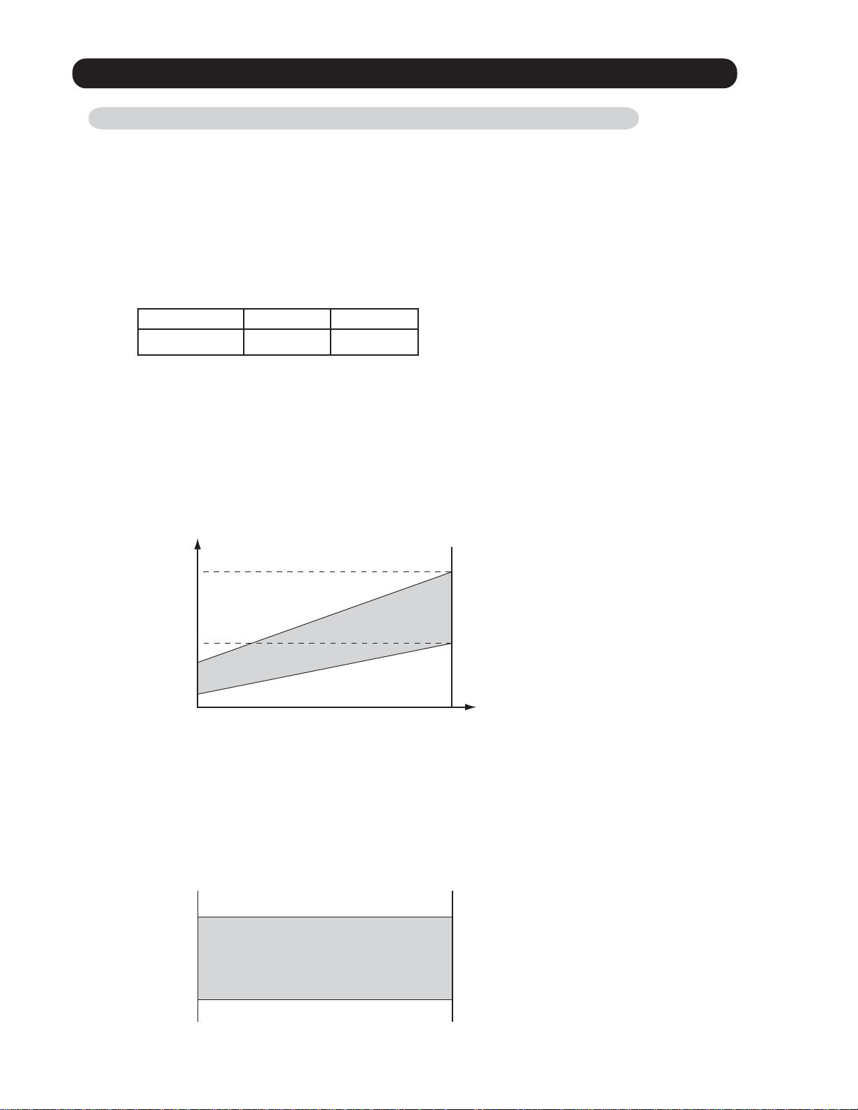
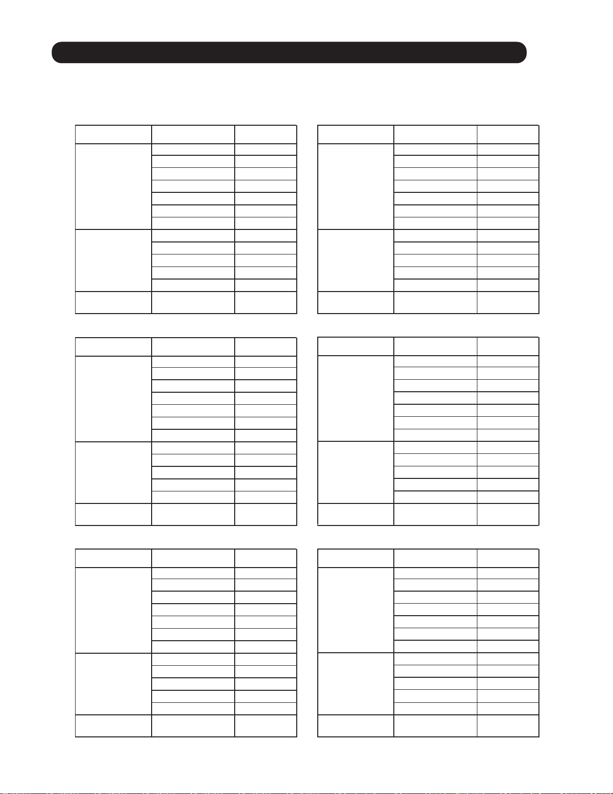
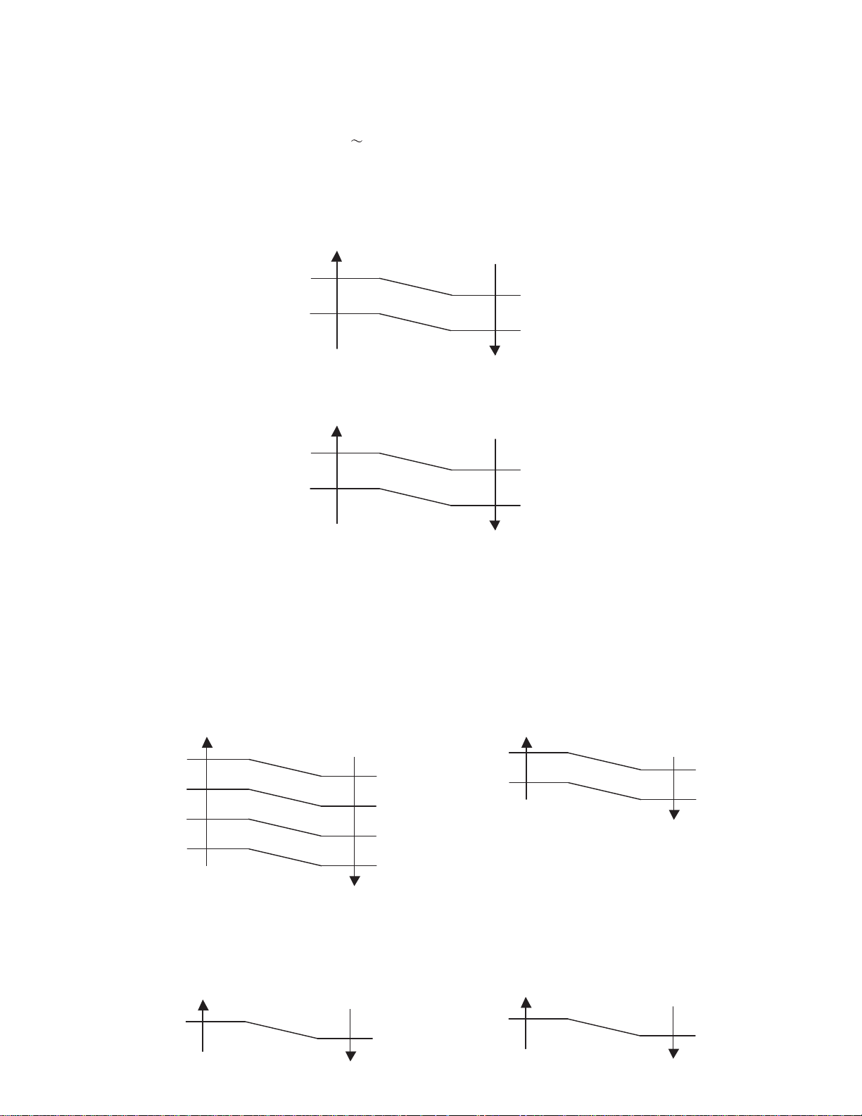
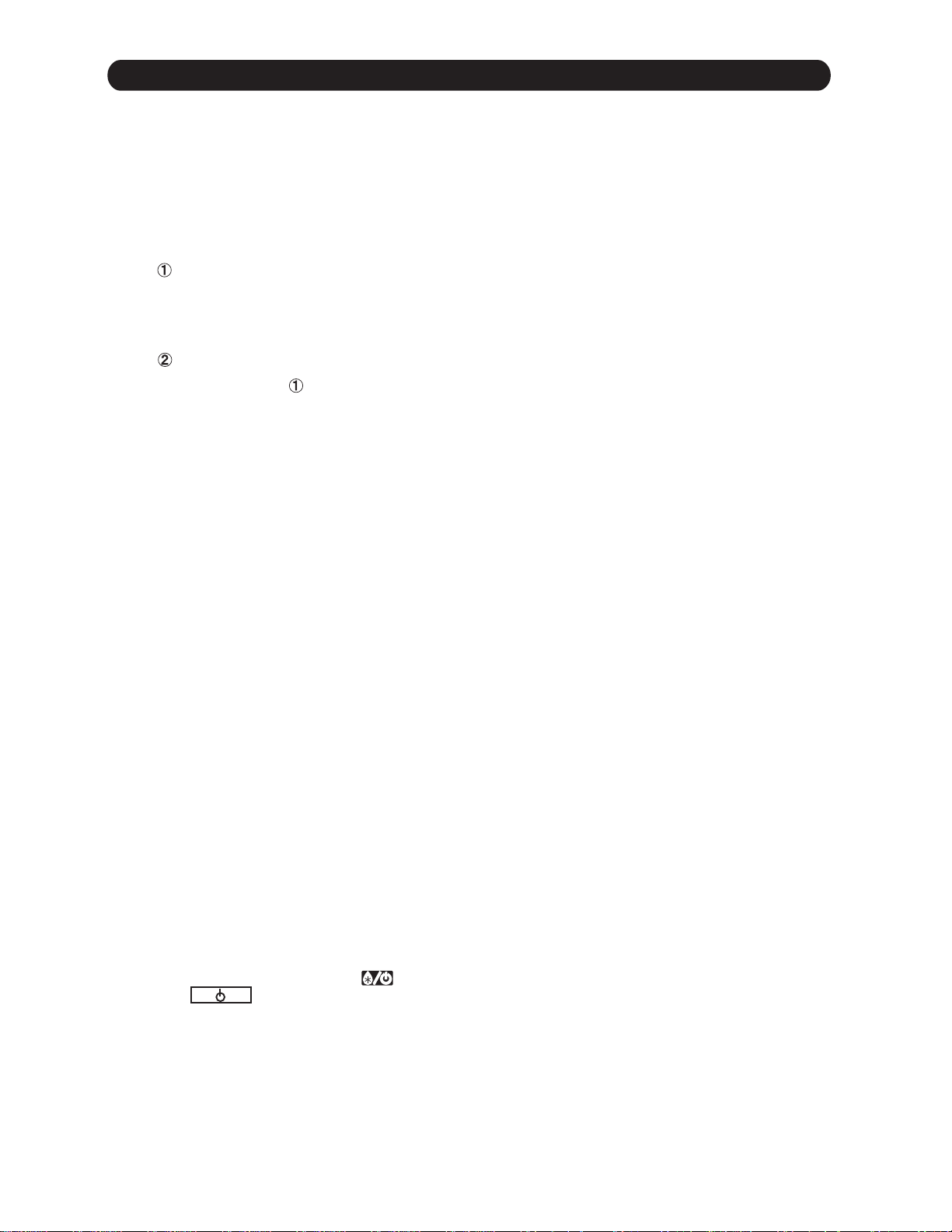
< Target high pressure control >
The outdoor fan speed is controlled to keep the high pressure to the constant range for stabilizing
the distribution performance.
90rps
High
pressure
478PSI
338PSI
275PSI
235PSI
( Fig. 1 : Target high pressure range)
Target high pressure
Outdoor
temperature
< Target low pressure control >
When the start-up control finished, the outdoor unit starts the target low pressure control.
The outdoor unit selects the target low pressure within the following range,
it is decided by the highest request capacity from indoor units.
( Fig. 2 : Target low pressure range)
184PSI
119PSI
Target low pressure
01-01
1-2. HEATING OPERATION
1-2-1. HEATING CAPACITY CONTROL
A sensor (room temperature thermistor) built in the indoor unit body will usually perceive
difference or variation between a set temperature and present room temperature,
and controls the operation speed of the compressor.
The outdoor unit operates according to the highest request capacity of indoor unit
to meet the demand capacity of all the indoor units.
The capacity control of the low request capacity indoor unit is controlled by Branch box EEV.
( Table 2 : Compressor speed range )
Minimum Maximum
AOU48RLXFZ
18rps
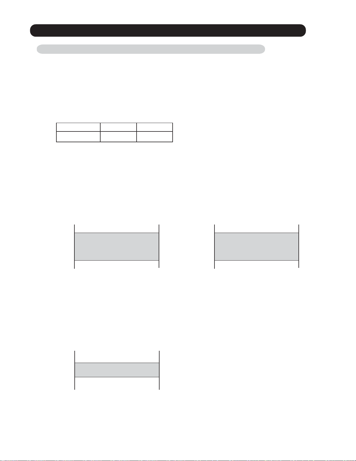
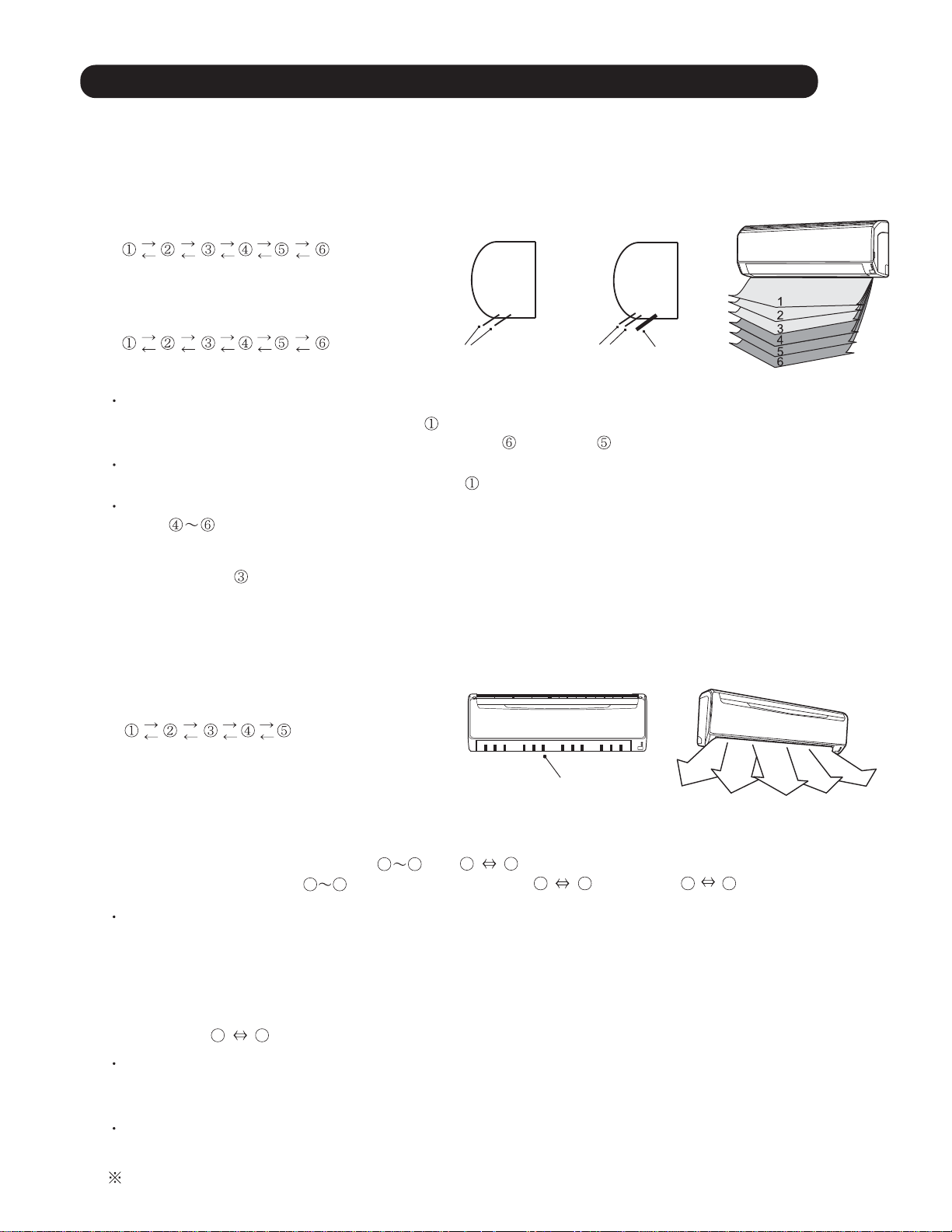
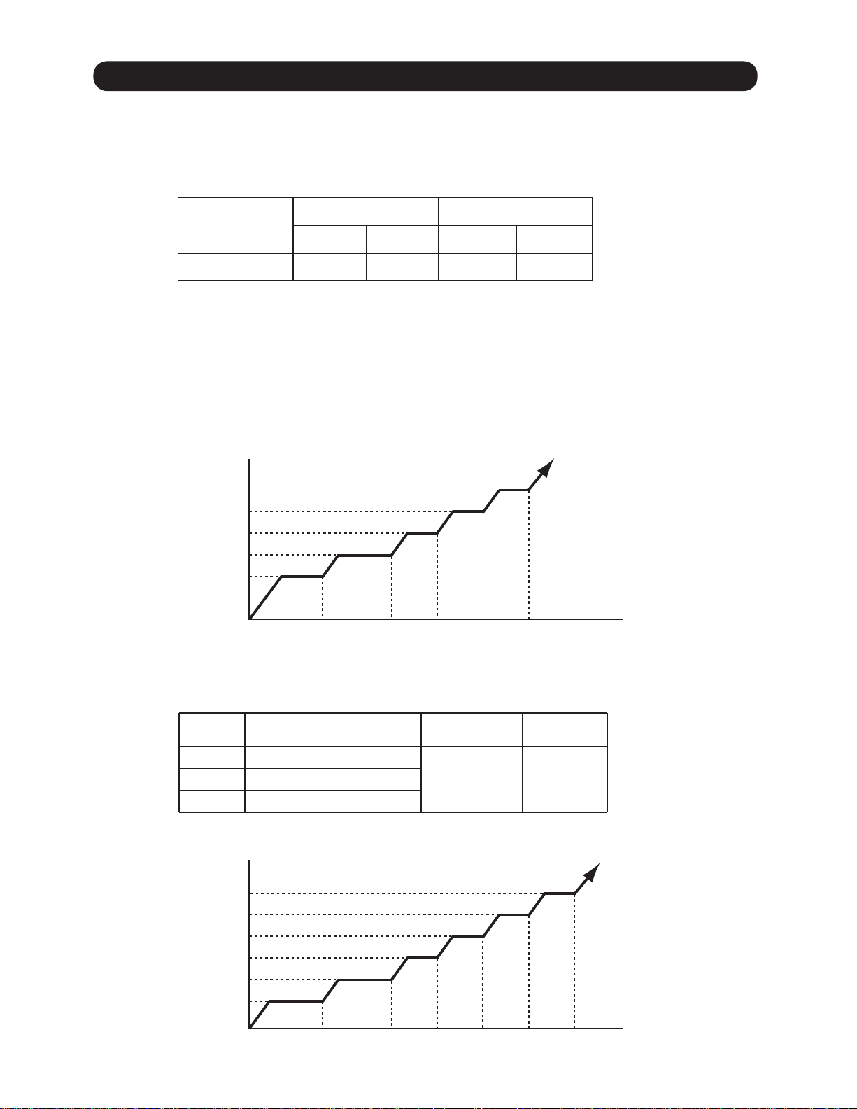
< Target high pressure control >
When the start-up control finished, the outdoor unit starts the target high pressure control.
The outdoor unit selects the target high pressure within the following range,
it is decided by the highest request capacity from indoor units.
96rps
( Fig. 3 : Target high pressure range
for NORMAL HEATING OPERATION)
451PSI
Target high pressure
328PSI
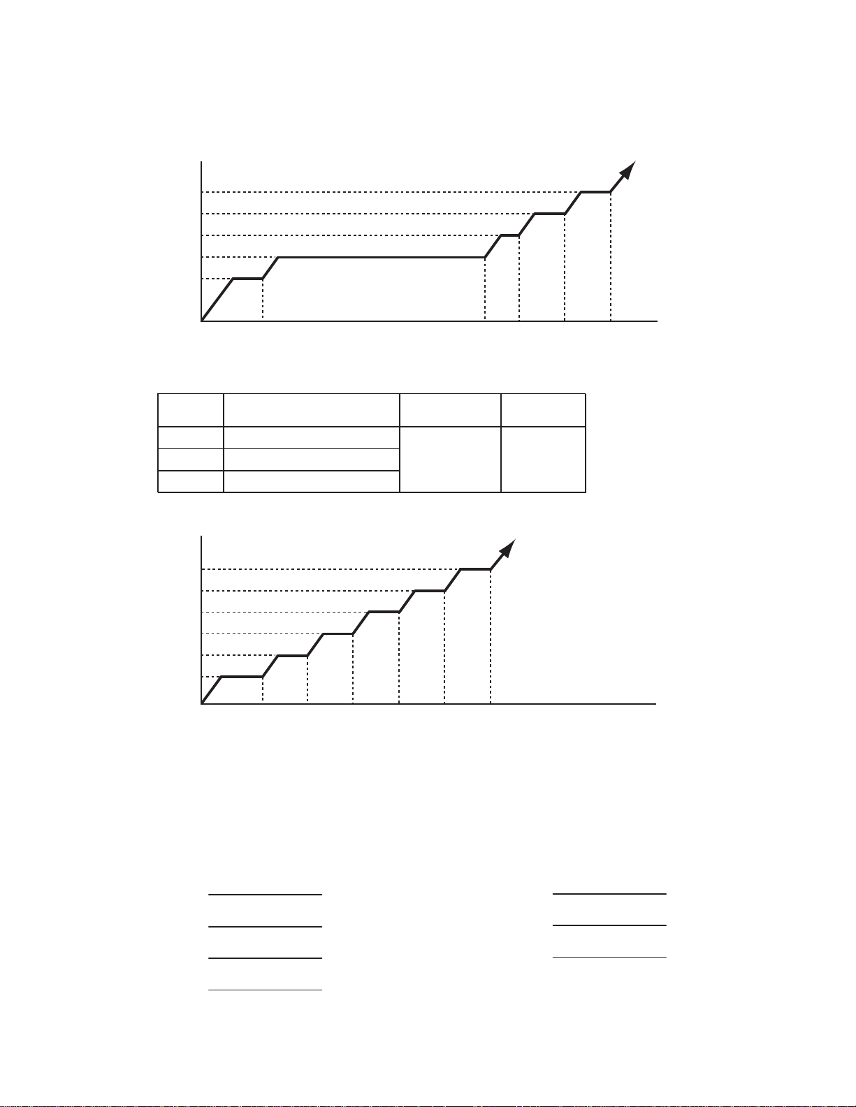
( Fig. 4 : Target high pressure range
for MIN. HEAT OPERATION)
272PSI
Target high pressure
190PSI
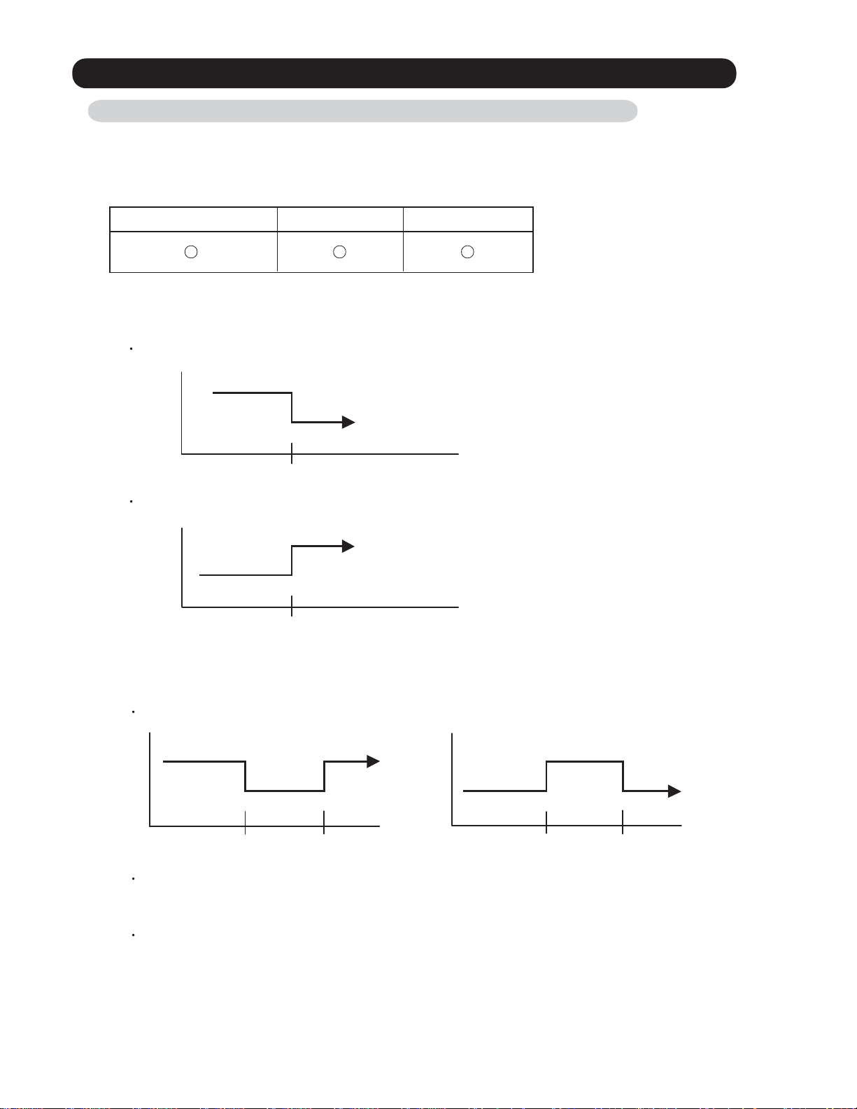
< Target low pressure control >
The outdoor fan speed is controlled to keep the low pressure to the constant range for the following reasons.
1. Frost prevention
2. Low pressure over rise prevention
( Fig. 5 : Target low pressure range)
123PSI
Target low pressure
109PSI
01-02
1-3. AUTO CHANGEOVER OPERATION
When the air conditioner is set to the Auto mode by remote controller, operation starts in the optimum
mode from among the Heating, Cooling, Dry and Monitoring mode. During operation, the
optimum mode is automatically switched in accordance with temperature changes. The temperature
can be set between 64°F(18°C) and 88°F(30°C) in 2°F(1°C) steps.
When operation starts, indoor fan and outdoor fan are operated for around 3 minutes.
1
Room temperature and outdoor temperature are sensed, and the operation mode is selected
in accordance with the table below. <Monitoring mode>
( Table 3 : Operation mode selection table )
Room temperature (TR)
TR> Ts+4°F(+2°C)
Operation mode
Cooling
(Autmatic dry)
TR : Room temperature
Ts : Setting temperature
Ts+4°F(+2°C) TR Ts -4°F(-2°C)
TR < Ts -4°F(-2°C) Heating
*Middle zone
*If it's Middle zone, operation mode of indoor unit is selected as below.
(1). Same operation mode is selected as outdoor unit.
If outdoor unit is operating in Cooling, Dry, and Heating mode,
indoor unit will be operated by the same operation mode.
(2). Selected by the outdoor temperature.
If outdoor unit is operating in other than Cooling, Dry, and Heating mode,
indoor unit will be operated according to the outdoor temperature as below.
( Fig. 6 : Outdoor temperature zone selection )
Cooling mode
77°F (25°C)
Heating mode
2
When Cooling or Dry mode was selected at and air flow mode is Auto, the air conditioner operates as follow.
The same operation as COOLING OPERATION AND DRY OPERATION of page 01-01 is performed.
When the room temperature has remained at set temperature -3°F(-1.5°C), operation is automatically
switched to Dry mode.
If the room temperature reaches set temperature +4°F(+2°C) during Dry mode, operation returns to Cooling.
( Fig.7 : Auto changeover : Cooling - Dry )
( Air flow mode : Auto )
Ts +2°F(+1°C)
Cooling
Cooling
Ts -3°F(-1.5°C)
(J zone)
Ts -5°F(-2.5°C)
Compressor stop
When the room
temperature drops
3
When Heating was selected at , the same operation as HEATING OPERATION of page
1
01-02 is performed.
Dry
1
Dry
(X zone)
Ts +4°F(+2°C)
Ts -1°F(-0.5°C)
Ts -3°F(-1.5°C)
When the room
temperature rises
TR : Room temperature
Ts : Setting temperature
4
When the compressor was stopped for 6 consecutive minutes by the temperature control function
after the Cooling(Auto:Dry) or Heating mode was selected at above, operation is switched
1
to Monitoring and the operation mode is selected again.
01-03
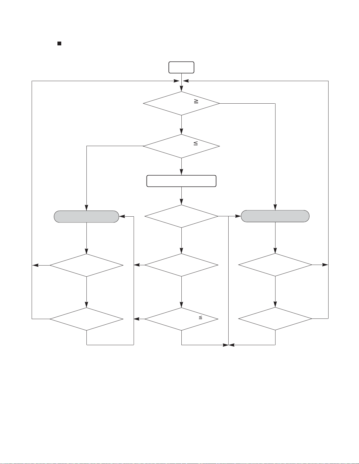
AUTO CHANGEOVER operation flow chart
HEATING OPERATION
YES
START
Room temp.
Ts+4°F(+2
°C)?
NO
Room temp.
Ts -4°F(-2
°C)?
NO
Middle zone
Operation mode of
outdoor unit : Cooling or Dry?
NO
YES
TS : Setting temperature
YES
COOLING (AUTO:DRY)
OPERATION
YES
YES
Thermostat remains
in OFF state for 6 minutes or
longer?
NO
System stops
or operation command other than
auto changeover operation?
NO
YES
YES
Operation mode of
outdoor unit : Heating?
NO
Outdoor temperature
77
°F(25°C)?
NO
Thermostat remains
in OFF state for 6 minutes or
longer?
NO
System stops
or operation command other than
auto changeover operation?
NO
YES
YES
01-04
1-4. INDOOR FAN CONTROL
1. Fan speed
( Table 4 : Indoor fan speed table)
ASU7RLF
ASU9RLF
Operation mode
Heating
Cooling / Fan
Dry
ASU12RLF
Operation mode
Heating
Cooling / Fan
Dry
Air flow mode
Hi
Me+
Me
Lo
Quiet
Cool Air Prevention
S-Lo
Hi
Me
Lo
Quiet
*Soft Quiet
Auto
Air flow mode
Hi
Me+
Me
Lo
Quiet
Cool Air Prevention
S-Lo
Hi
Me
Lo
Quiet
*Soft Quiet
Auto
Fan Speed
1050
1000
950
850
720
600
480
1050
950
850
710
600
X, J zone:710
Fan Speed
1200
1130
1050
910
720
600
480
1200
1050
880
710
600
X, J zone:710
Operation mode
Heating
Cooling / Fan
Dry
ASU18RLF
Operation mode
Heating
Cooling / Fan
Dry
Air flow mode
Hi
Me+
Me
Lo
Quiet
Cool Air Prevention
S-Lo
Hi
Me
Lo
Quiet
*Soft Quiet
Auto
Air flow mode
Hi
Me+
Me
Lo
Quiet
Cool Air Prevention
S-Lo
Hi
Me
Lo
Quiet
*Soft Quiet
Auto
Fan Speed
1100
1040
980
850
720
600
480
1100
980
850
710
600
X, J zone:710
Fan Speed
1260
1120
1020
900
790
680
480
1260
1020
900
770
680
X, J zone:770
ASU24RLF
Operation mode
Heating
Cooling / Fan
Dry
Air flow mode
Hi
Me+
Me
Lo
Quiet
Cool Air Prevention
S-Lo
Hi
Me
Lo
Quiet
*Soft Quiet
Auto
Fan Speed
1430
1320
1220
1020
900
720
480
1480
1220
1020
900
720
X, J zone:900
AUU9RLF
Operation mode
Heating
Cooling / Fan
Dry
Air flow mode
Cool Air Prevention
*Soft Quiet
*Note, during Economy operation and operation mode is Fan, air flow is 1 step downs.
(Hi > Me, Me > Lo, Quiet > Soft Quiet)
01-05
Hi
Me+
Me
Lo
Quiet
S-Lo
Hi
Me
Lo
Quiet
Auto
Fan Speed
590
570
540
490
440
400
300
590
540
490
440
400
X, J zone:440
AUU12RLF
AUU18RLF
Operation mode
Heating
Cooling / Fan
Dry
Air flow mode
Hi
Me+
Me
Lo
Quiet
Cool Air Prevention
S-Lo
Hi
Me
Lo
Quiet
Soft Quiet
Auto
ARU9RLF (Static pressure:25Pa)
Operation mode
Heating
Cooling / Fan
Dry
Air flow mode
Hi
Me
Lo
Quiet
S-Lo
Hi
Me
Lo
Quiet
Soft Quiet
Auto
Fan Speed
650
620
580
520
460
400
300
660
580
520
460
400
X, J zone:460
Fan Speed
1260
1160
1060
960
500
1260
1160
1060
960
500
X, J zone:960
Operation mode
Heating
Cooling / Fan
Dry
Air flow mode
Hi
Me+
Me
Lo
Quiet
Cool Air Prevention
S-Lo
Hi
Me
Lo
Quiet
Soft Quiet
Auto
ARU12RLF (Static pressure:25Pa)
Operation mode
Heating
Cooling / Fan
Dry
Air flow mode
Hi
Me
Lo
Quiet
S-Lo
Hi
Me
Lo
Quiet
Soft Quiet
Auto
Fan Speed
840
800
750
650
500
400
300
790
660
570
460
400
X, J zone:460
Fan Speed
1340
1240
1140
1030
500
1340
1240
1140
1030
500
X, J zone:1030
ARU18RLF (Static pressure:25Pa)
Operation mode
Heating
Cooling / Fan
Dry
Air flow mode
Hi
Me
Lo
Quiet
S-Lo
Hi
Me
Lo
Quiet
Soft Quiet
Auto
Fan Speed
1380
1300
1220
1140
600
1380
1300
1220
1140
600
X, J zone:1140
ARU24RLF (Static pressure:25Pa)
Operation mode
Heating
Cooling / Fan
Dry
01-06
Air flow mode
Hi
Me
Lo
Quiet
S-Lo
Hi
Me
Lo
Quiet
Soft Quiet
Auto
Fan Speed
1460
1360
1260
1180
600
1460
1360
1260
1180
600
X, J zone:1180
2. FAN OPERATION
The airflow can be switched in 5 steps such as Auto, Quiet, Lo, Me, Hi,
while the indoor fan only runs.
When Fan mode is set at (Auto), it operates on (Me) Fan Speed.
< All models >
3. COOLING OPERATION (Auto : Cooling)
Switch the airflow [Auto], and the indoor fan motor will run according to a room temperature,
as shown in Fig 8.
On the other hand, if switched in [Hi] [Quiet], the indoor motor will run at a constant airflow of [Cooling]
operation modes Quiet, Lo, Me, Hi.
( Fig.8 : Airflow change - over )
TR-Ts > +4°F(+2°C)
=
+4
°F(+2°C) > TR-Ts > +2°F(+1°C)
=
+2
=
°F(+1°C) > TR-Ts
=
When the room
temperature drops
< All models >
Hi
Me
Lo
TR-Ts > +5
+5
°F(+2.5°C) > TR-Ts > +3°F(+1.5°C)
°F(+1.5°C) > TR-Ts
+3
When the room
temperature rises
=
TR : Room temperature
Ts : Setting temperature
°F(+2.5°C)
=
=
=
4. DRY OPERATION (Auto : Dry)
During the dry operation, the fan speed setting can not be changed,
it operates automatically as shown in Fig. 8
Room temperature variation which the room temperature sensor of the indoor unit body has detected.
( Fig. 9 : Indoor fan control )
< Compressor >
ON
OFF
< Indoor fan air flow mode >
Setting air flow
S-Lo
Fan OFF
10 30 60 180 60 180 60 10 30 (sec)
< All models >
01-07
5. HEATING OPERATION
Switch the airflow [Auto], and the indoor fan motor will run according to a room temperature,
as shown in Fig 10.
On the other hand, if switched in [Hi] [Quiet], the indoor motor will run at a constant airflow
of [Heat] operation modes Quiet, Lo, Me, Hi, as shown in Table 4.
( Fig.10 : Airflow change - over ( Heating : Auto ) )
< ASU7/9/12/18/24RLF >
When the room
temperature rises
TR-Ts > -2
°F(-1°C) > TR-Ts > -4°F(-2°C)
-2
°F(-1°C) > TR-Ts > -4°F(-2°C)
-2
=
°F(-2°C) > TR-Ts
-4
TR-Ts > -2
=
-4
°F(-2°C) > TR-Ts
°F(-1°C)
=
When the room
temperature rises
°F(-1°C)
=
When the room
Lo
Me
Me+
temperature drops
TR-Ts > -3°F(-1.5°C)
-3°F(-1.5°C) > TR-Ts > -5°F(-2.5°C)
-5
°F(-2.5°C) > TR-Ts
< AUU9/12/18RLF, ARU9/12/18/24RLF >
When the room
Lo
Me
Hi
temperature drops
TR-Ts > -3°F(-1.5°C)
-3°F(-1.5°C) > TR-Ts > -5°F(-2.5°C)
°F(-2.5°C) > TR-Ts
-5
=
=
TR : Room temperature
Ts : Setting temperature
=
=
6. COOL AIR PREVENTION CONTROL (For Heating and Min. Heat operation)
The maximum value of the indoor fan speed is set as shown in Fig 10, based on the detected
temperature by the indoor heat exchanger sensor in heating mode.
Field setting is necessary at AR and AU type as "Cool air prevention : effective"
( Fig.11 : Airflow change - over for cool air prevention)
During NORMAL HEATING OPERATION
< ASU7/9/12/18/24RLF, AUU9/12/18RLF >
When Indoor
heat exchanger
temperature rises
107.6°F
(42°C)
°F
102.2
(39°C)
°F
98.6
(37°C)
86
°F
(30°C)
Hi
*Me+ or setting
FAN mode
*Lo or setting
FAN mode
Cool air
prevention
S-Lo
When Indoor
heat exchanger
temperature drops
98.6
(37°C)
93.2
(34°C)
89.6
(32°C)
82.4
(28°C)
°F
°F
°F
°F
When Indoor
heat exchanger
temperature rises
98.6°F
(37°C)
84.2°F
(29°C)
< ARU9/12/18/24RLF >
*Hi or setting
FAN mode
*Lo or setting
FAN mode
S-Lo
*Lower speed is selected
*Lower speed is selected
During MIN. HEAT OPERATION
< ASU7/9/12/18/24RLF, AUU9/12/18RLF >
When Indoor
heat exchanger
temperature rises
102.2°F
(39°C)
Auto
Lo
When Indoor
heat exchanger
temperature drops
93.2°F
(34°C)
When Indoor
heat exchanger
temperature rises
98.6
(37°C)
< ARU9/12/18/24RLF >
Auto
°F
Lo
When Indoor
heat exchanger
temperature drops
°F
89.6
(32°C)
75.2
°F
(24°C)
When Indoor
heat exchanger
temperature drops
89.6°F
(32°C)
01-08
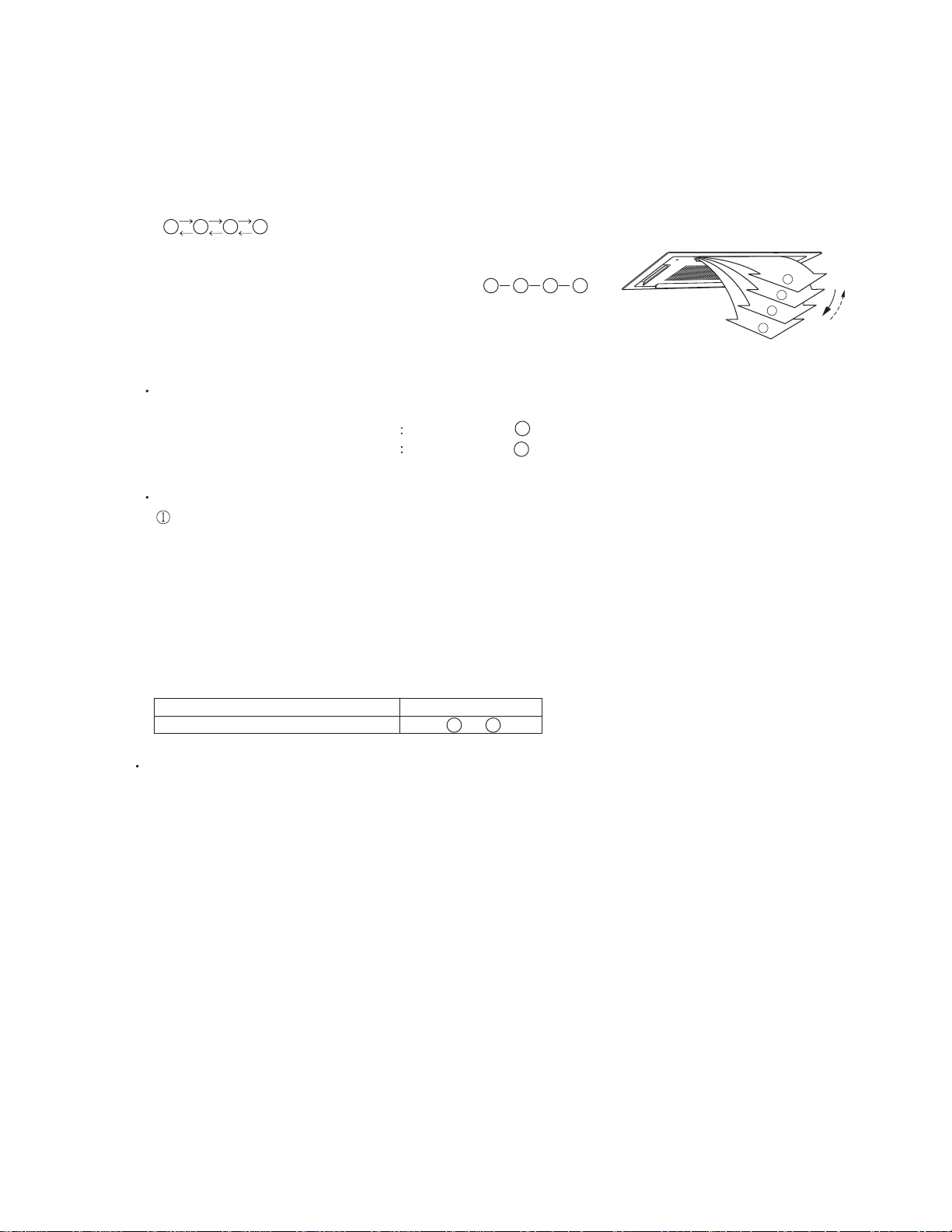
1-5. LOUVER CONTROL
For Compact Wall Mounted Type, Wall Mounted Type < ASU7/ 9/ 12/ 18/ 24RLF >
1. VERTICAL LOUVER CONTROL
(Function Range)
Each time the button is pressed, the air direction range
will change as follow:
(Table9 : Recommended Operation Range)
Cooling / Heating / Dry mode / Fan mode
(Fig.12 : Virtical Air Direction Range)
<Wall Mounted Type><Compact Wall Mounted Type>
Vertical Louver
Power DiffuserVertical Louver
Use the air direction adjustments within the ranges shown above.
The vertical airflow direction is set automatically as shown, in accordance with the type of operation selected.
Cooling / Dry mode : Horizontal flow
Heating mode : Downward flow ASU7/9/12: , ASU18/24:
When the temperature of the air being blown out is low at the start of heating operation or during
defrosting, the airflow direction temporarily becomes to prevent cold air being blown onto the body.
During use of the Cooling and Dry modes, do not set the Air Flow Direction Louver in the Heating
range ( ) for long period of time, since water vapor many condense near the outlet louvers and
drop of water may drip from the air conditioner. During the Cooling and Dry modes, if the Air Flow
Direction Louvers are left in the heating range for around 30 minutes, they will automatically
return to position .
2. HORIZONTAL LOUVER CONTROL (For ASU18/ 24RLF)
(Function Range)
Each time the button is pressed, the air direction
range will change as follows.
ASU7/9/12RLF changes by manual.
Cooling / Heating / Dry mode / Fan mode
3. SWING OPERATION
Vertical Airflow Swing Operation
When the swing signal is received from the remote controller, the vertical louver starts to swing.
(Swinging Range)
Cooling mode / Dry mode / Fan mode( ) :
Heating mode / Fan mode( ) : ASU7/9/12 [ ], ASU18/24 [ ]
4
1 3
6
1
(Fig.13 : Horizontal Air Direction Range)
1
Horizontal Louver
4
6
4
36
2
3
5
4
When the indoor fan is S-Lo or Stop mode, the swing operation is interrupted
and it stops at either upper end or bottom end.
Horizontal Airflow Swing Operation (For ASU18/24RLF )
When the swing signal is received from the remote controller, the horizontal louver starts to swing.
(Swinging Range)
All mode :
1
5
When the indoor fan is S-Lo or Stop mode, the swing operation is interrupted
and it stops at either upper end or bottom end.
Vertical and Horizontal Airflow Swing Operation
When the horizontal swing signal is input from remote control, the combination of the vertical
and horizontal swing operation is performed.
Power Diffuser doesn't swing in any swing operation.
01-09
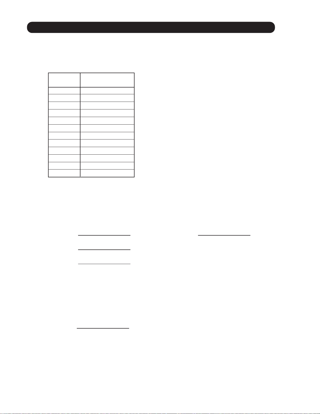
For Compact Cassette Type < AUU9/ 12/ 18RLF >
1. VERTICAL LOUVER CONTROL
(Function Range)
Each time the button is pressed, the air direction range will change as follows:
1234
(Operation Range)
During COOLING / HEATING / DRY / FAN mode :
1234
(Fig.14 : Air Direction Range)
3
4
Use the air direction adjustments within the ranges shown above.
The vertical airflow direction is set automatically as shown, in accordance with the type of operation
selected.
COOLING / DRY / FAN mode
HEATING mode
Horizontal flow
Downward flow
1
4
During AUTO mode operation, for the first minute after start-up, air-flow will be horizontal
; the air direction cannot be adjusted during this period.
2. SWING OPERATION
When the swing signal is received from the remote controller, the vertical louver starts to swing.
The range of swing depends on the set airflow direction.
1
2
The type of operation
COOLING / HEATING / DRY / FAN
Range of swing
to
14
When the indoor fan is either at S-Lo or Stop mode, the swinging operation is interrupted
and the louver stops at the memorized position.
( Stop mode means Operation stop.)
01-10
1-6. OUTDOOR FAN CONTROL
1. Fan speed table
Table 5 shows the fan speed of the outdoor unit.
( Table 5 : Outdoor fan speed table)
AOU48RLXFZ
Fan step
0
1
2
3
4
5
6
7
8
9
10
11
Fan speed
0
250
290
340
390
460
580
690
800
890
910
950
[rpm]
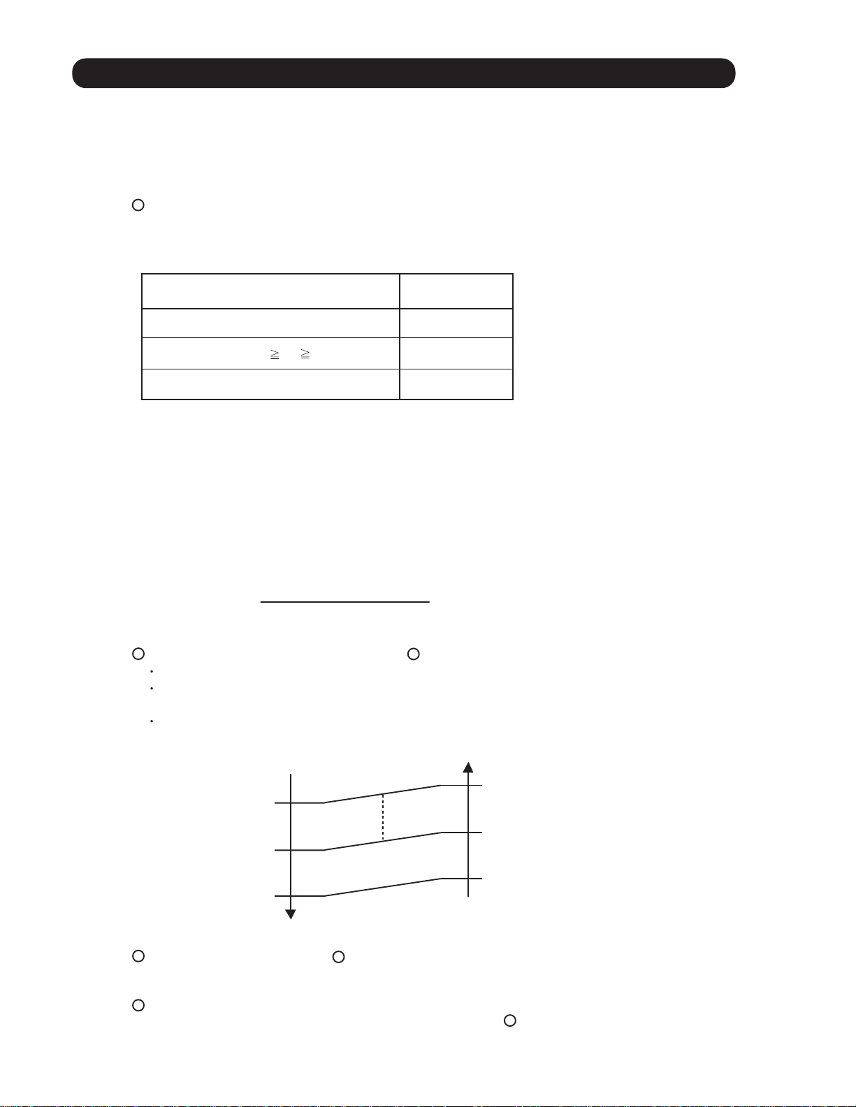
2. Limit of fan speed range
Fig.15 shows the limit of fan speed range changes by outdoor temperature.
( Fig.15 : Limit of fan speed range )
Outdoor
temperature
86°F(30°C)
68°F(20°C)
50°F(10°C)
< Cooling and Dry mode >
890rpm
580 ~ 890rpm
250 ~ 890rpm
0 ~ 890rpm
Outdoor
temperature
41°F(5°C)
< Heating mode >
460 ~ 910rpm
460 ~ 950rpm
3. Initial fan speed control
Initial fan speed is decided by outdoor temperature.
( Fig.16 : Initial fan speed range )
< Cooling and Dry mode >
Outdoor
temperature
690rpm
50°F(10°C)
390rpm
If the fan motor is running over than 400rpm, it start up process is stopped in all conditions. [ Prevent the big wind operation ]
*
When the fan motor is stopped, it can not restart for 10 seconds.
*
Even if during EEV initialization, outdoor unit fan starts.
*
01-11
< Heating mode >
Fixed at 690rpm
1-7. COMPRESSOR CONTROL
1. OPERATION SPEED RANGE
The operation speed of the compressor is different based on the operation mode as
shown in theTable 6.
( Table 6 : Compressor operation speed range )
Heating
Minimum Maximum
18rps 96rps
AOU48RLXFZ
Dry / Cooling
Minimum Maximum
18rps
90rps
2. OPERATION SPEED CONTROL AT START-UP
The compressor speed soon after the start-up is controlled for
2-1 Cooling and Dry start-up procces
< Pattern 1 >
If it does not meet the condition of pattern 2, the compressor will start at pattern 1.
( Fig.17 : Pttern 1)
(rps)
70
limit
54
47
40
33
Upper
speed
90
180 240
Elapsed time
< Pattern 2 >
If it meets one of the following conditions, the compressor will start at pattern 2.
Condition
1
2
3
Compressor control
before operation stops
Target pressure control
Start-up procces 2
Oil recovery / Defrost
Stop time of
compressor
Below 3 hours
Compressor
temperature
Over 32°C
( Fig.18 : Pattern 2)
(rps)
54
Upper
speed
limit
47
40
33
20
(sec)300 330
90
180 240
Elapsed time
01-12
(sec)300 36070390
2-2 Heating start-up procces
< Pattern 1 >
If it does not meet the condition of pattern 2, the compressor will start at pattern 1.
( Fig.19 : Heating start-up pattern 1)
(rps)
70
limit
60
47
40
33
Upper
speed
90
Elapsed time
690 720
< Pattern 2 >
If it meets one of the following conditions, the compressor will start at pattern 2.
Condition
1
2
3
Compressor control
before operation stops
Target pressure control
Start-up procces 2
Oil recovery / Defrost
Stop time of
compressor
Below 3 hours
Compressor
temperature
Over 89.6°F
(32°C)
( Fig.20 : Heating start-up pattern 2)
(rps)
60
Upper
speed
limit
47
40
33
20
90
150 210
Elapsed time
(sec)780 840
(sec)270 33070390
3. LIMIT OF THE COMPRESSOR SPEED RANGE
The compressor speed range is limited by outdoor temperature as shown in Fig.21
( Fig.21 : Limit of the compressor speed range )
< Cooling and Dry mode >
Outdoor
temperature
21 ~ 90rps
104°F(40°C)
18 ~ 90rps
50°F(10°C)
25 ~ 90rps
23°F(-5°C)
27 ~ 90rps
14°F(-10°C)
* 0rps
*Protection stop for low outdoor temperature.
It will be released when outdoor temperature
becomes over than 14°F(-10°C)
01-13
Outdoor
temperature
53.6°F(12°C)
41°F(5°C)
5°F(-15°C)
< Heating mode >
21 ~ 90rps
18 ~ 96rps
23 ~ 96rps
25 ~ 96rps
1-8. TIMER OPEARTION CONTROL
1-8-1 WIRELESS REMOTE CONTROLLER
The table 7 shows the available timer setting based on the product model.
( Table 7 : Timer setting )
ON TIMER / OFF TIMER PROGRAM TIMER SLEEP TIMER
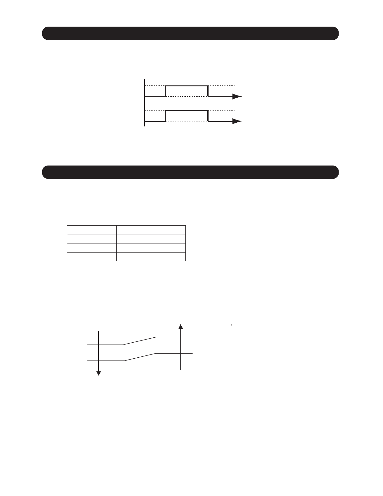
1. ON / OFF TIMER
OFF timer : When the clock reaches the set time, the air conditioner will be turned off.
Operation mode
Stop mode
Set time of timer
ON timer : When the clock reaches the set time, the air conditioner will be turned on.
Operation mode
Stop mode
Set time of timer
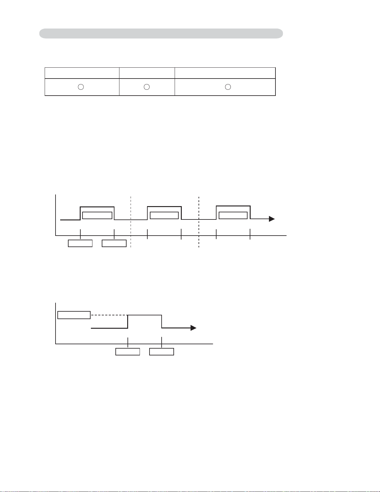
2. PROGRAM TIMER
The program timer allows the OFF timer and ON timer to be used in combination one time.
Operation mode
Stop mode
Set time Set time Set time Set time
Operation will start from the timer setting (either OFF timer or ON timer) whichever is closest
to the clock's current timer setting.
The order of operations is indicated by the arrow in the remote control unit's display.
Operation mode
Operation mode
Stop mode
Stop mode
SLEEP timer operation cannot be combined with ON timer operation.
01-14
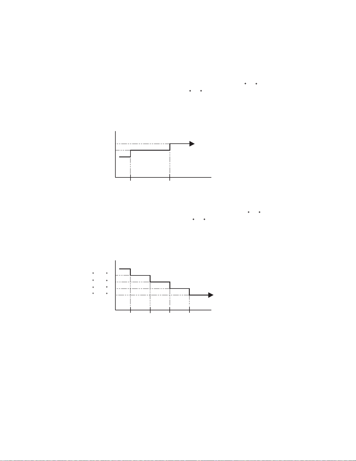
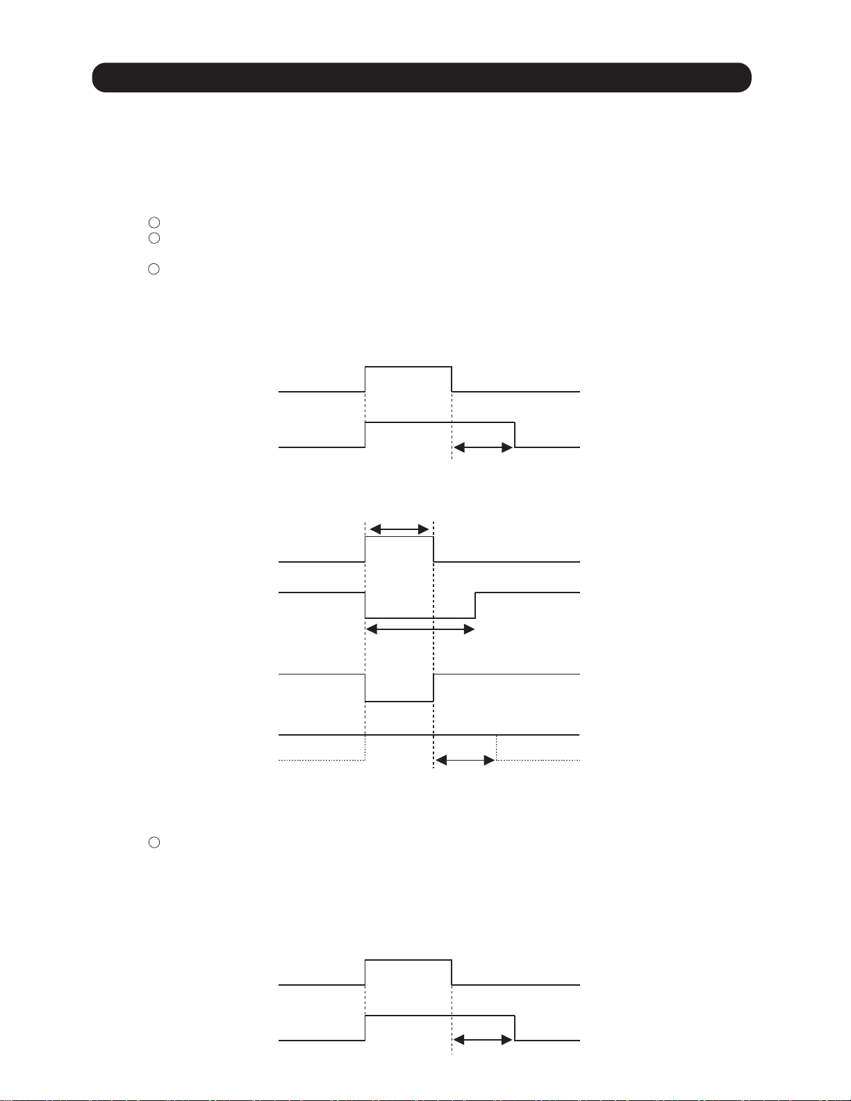
3. SLEEP TIMER
If the sleep is set, the room temperature is monitored and the operation is stopped automatically.
If the operation mode or the set temperature is change after the sleep timer is set, the operation is
continued according to the changed setting of the sleep timer from that time ON.
In the cooling operation mode
When the sleep timer is set, the setting temperature is increased 2 F(1 C).
It increases the setting temperature another 2 F(1 C) after 1 hour.
After that, the setting temperature is not changed and the operation is stopped at the time
of timer setting.
Set temperature rises
( Ts : Set temperature )
+4°F (+2°C)
+2°F (+1°C)
Ts
Stop of operation
Set
60min
In the heating operation mode
When the sleep timer is set, the setting temperature is decreased 2 F(1 C).
It decreases the setting temperature another 2 F(1 C) every 30 minutes.
Upon lowering 4deg C, the setting temperature is not changed and the operation stops at
the time of timer setting.
Set temperature lowers
( Ts : Set temperature )
Ts
-2 F(-1 C)
-4 F(-2 C)
-6 F(-3 C)
-8 F(-4 C)
Stop of operation
Set
30min
30min
30min
01-15
1-8-2 WIRED REMOTE CONTROLLER
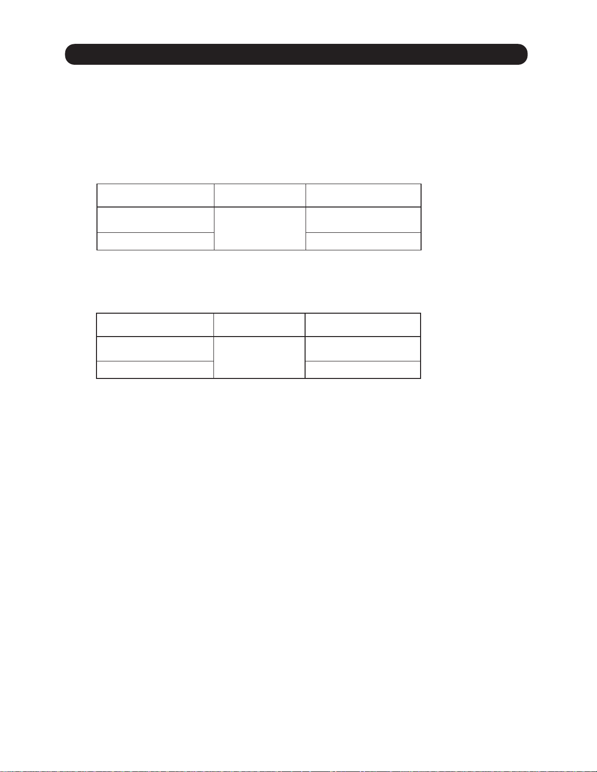
The Table 8 shows the available timer setting based on the product model.
( Table 8 : Timer setting )
ON TIMER / OFF TIMER WEEKLY TIMER TEMPERATURE SET BACK TIMER
1. ON TIMER / OFF TIMER
Same to 1-8-1 ON / OFF TIMER and shown in those.
2. WEEKLY TIMER
This timer function can set operation times of the each day of the week.
All days can be set together,the weekly timer can be used to repeat the timer setting for all of the days.
ON OFF ON OFF ON OFF
Setting day Setting day Setting day
Set time Set time
3. TEMPERATURE SET BACK TIMER
This timer function can change setting temperature of setting operation times of the each day of the week.
This can be together with other timer setting.
Set back tmp.
Normal tmp.
ON
Set time Set time
OFF
01-16
1-9. ELECTRONIC EXPANSION VALVE CONTROL
The most proper opening of the electronic expansion valve is calculated and controlled under the
present operating condition based on the following values.
The compressor frequency, the temperatures detected by the discharge temperature sensor, the
indoor heat exchanger sensor, the outdoor heat exchanger sensor, and the outdoor temperature
sensor.
1. Pulse range
(Table 9 : Pulse range of outdoor unit EEV)
Outdoor unit
Main EEV
Subcool EEV
Operation mode
Dry / Cooling
Heating
During heating operation, lower limit is 0 pulse.
Pulse range
40 ~ 480
35 ~ 480
(Table 10 : Pulse range of branch box EEV)
Branch box
Main EEV
Bypass EEV
Operation mode
Dry / Cooling
Heating
There is a case that EEV is full close at 32 10 pulse.
Pulse range
32 ~ 480
0 ~ 480
+
-
2. Initialization
Initialization (Input of 528 pulses toward closing direction) is operated under the following conditions.
It apply to all of EEV.
< Initialization conditions >
.
Power-on.
.
4 hours has passed from the last initialization, and when the compressor starts.
.
If 12 hours has passed from the last initialization, the compressor is compulsorily stopped.
.
3 minutes has passed from the protection stop of outdoor unit.
01-17

1-10. TEST OPERATION CONTROL
< Pre-test run check items >
Before the test run, refer to the figure and check the following items.
1. Is check run performed? Test run doesn't operate if check run is not performed.
After checking that the above items are all in order, refer to Test run method "to test run the unit.
If there are problems, adjust immediately and recheck.
< Test run method >
Be sure to configure test run settings only when the outdoor unit has stopped operating.
Depending on the communication status between the indoor and outdoor units, it may take several minutes for •
the system to start operating after settings for the test run are complete.
After the test run settings are complete, all the outdoor units and the connected indoor units will start operating. •
Room temperature control will not activate during test run (continuous operation).
Test run set with the outdoor unit doesn't stop automatically. Be sure to stop the operation according to the •
operation method.
All indoor units will operate when test run is performed from the outdoor unit. At this time, the remote controller of •
the indoor unit is unavailable.
Operation mode cannot be changed during the test run. To change the operation mode, please stop the test run •
first, and then perform the test run again. At this time, the compressor cannot be restarted for three minutes after
it stops in order to protect the indoor unit. Please restarte it after three minutes.
With Wired Remote Controller
Under the condition where the air conditioner stops, press the MODE button and the FAN button
simultaneously for 2 seconds or more, and the test operation control mode will appear.
During test running, " " will display on the remote controller display.
Set the test operation mode, and the compressor will continue to run regardless of whatever
the room temperature sensor detects.
With Wireless Remote Controller
Under the condition where the air conditioner runs, press the TEST RUN button, and
the test operation control mode will appear.
During test running, the Operation LED and Timer LED of the air conditioner body blinks simultaneously.
Set the test operation mode, and the compressor will continue to run regardless of whether the room
temperature sensor detects.
With Outdoor Unit
All the indoor units connected to the outdoor unit can be test-operated by push button as next page.
01-18
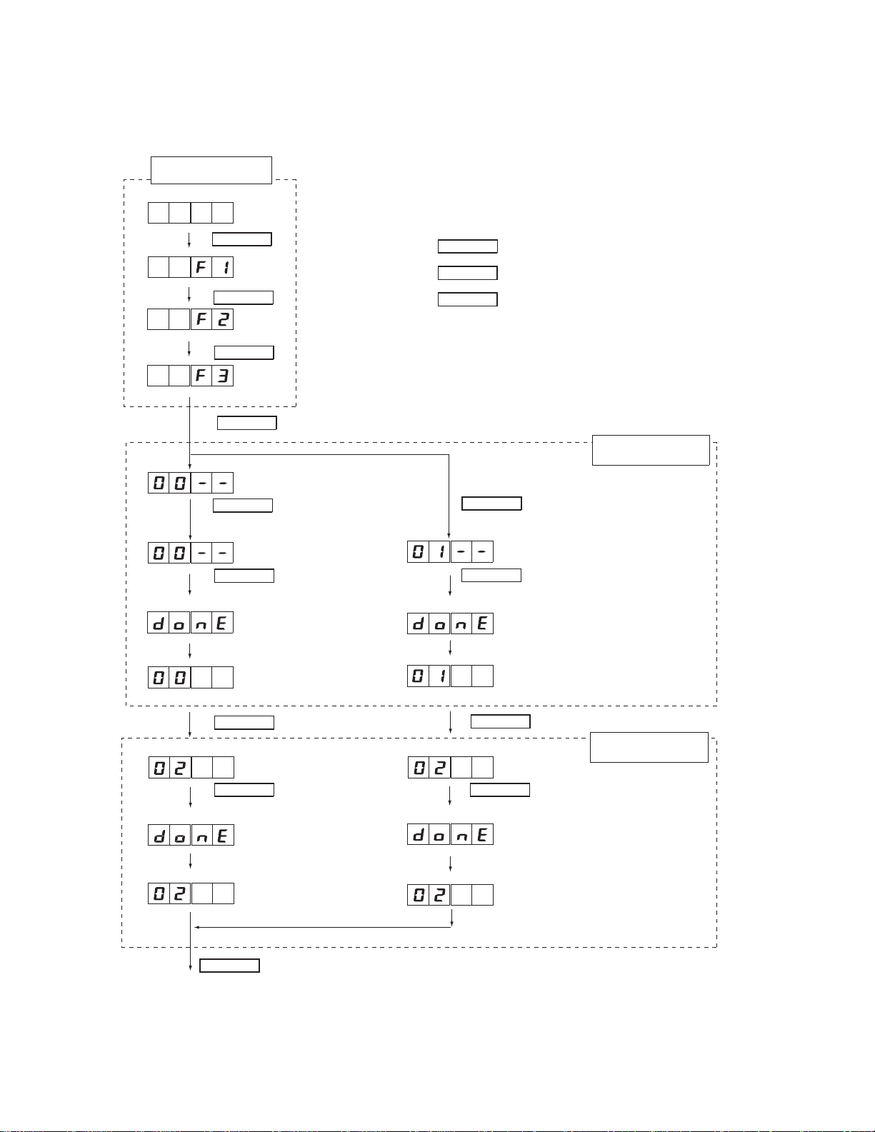
Perform test run for refrigerant system.
You can set “cooling test run” or “heating test run” with the push-button switch on the outdoor unit print circuit board.
Test run setting method
Function settings
First 2 digits
(Blinking)
(Blinking)
(Blinking)
Last 2 digits
MODE/EXIT
(Blinking)
SELECT
(Blinking)
SELECT
ENTER
SELECT
For cooling operation, press the
SELECT button until
ENTER
Press the ENTER button for
more than 3 seconds.
This will be displayed when the
cooling test run starts.
(It takes approximately 30 seconds for
the outdoor unit to start its operation.)
This will be displayed
after 5 seconds.
MODE/EXIT
SELECT
ENTER
(When [F4] to [F9] are displayed, continue to press
the SELECT button until [F3] is displayed.)
SELECT
For heating operation, press the
is displayed.
“00”
(Blinking)
(Blinking)
SELECT button until
ENTER
Press the ENTER button for
more than 3 seconds.
This will be displayed when the
heating test run starts.
This will be displayed
after 5 seconds.
: Press the “MODE/EXIT” button.
: Press the “SELECT” button.
: Press the “ENTER” button.
Settings for starting
test run operation
is displayed.
“01”
(It takes approximately 30 seconds for
the outdoor unit to start its operation.)
SELECT
SELECT
Settings for stopping
test run operation
(Blinking)
(Blinking)
ENTER
Press the ENTER button for
more than 3 seconds.
This will be displayed when the
cooling operation mode is canceled.
(It takes approximately 30 seconds for
the outdoor unit to stop its operation.)
This will be displayed
after 5 seconds.
MODE/EXIT
(Blinking)
(Blinking)
ENTER
Press the ENTER button for
more than 3 seconds.
This will be displayed when the heating
operation mode is canceled.
(It takes approximately 30 seconds for
the outdoor unit to stop its operation.)
This will be displayed
after 5 seconds.
EXIT
After the test run is complete, turn off the power. Attach the cover of the electrical component box and the front panel
of the outdoor unit.
01-19
1-11. 4-WAY VALVE EXTENSION SELECT
At the time when the air conditioner is switched from the Cooling mode to Heating mode,
the compressor is stopped, and the 4-way valve is switched in 3 minutes later
after the compressor stopped.
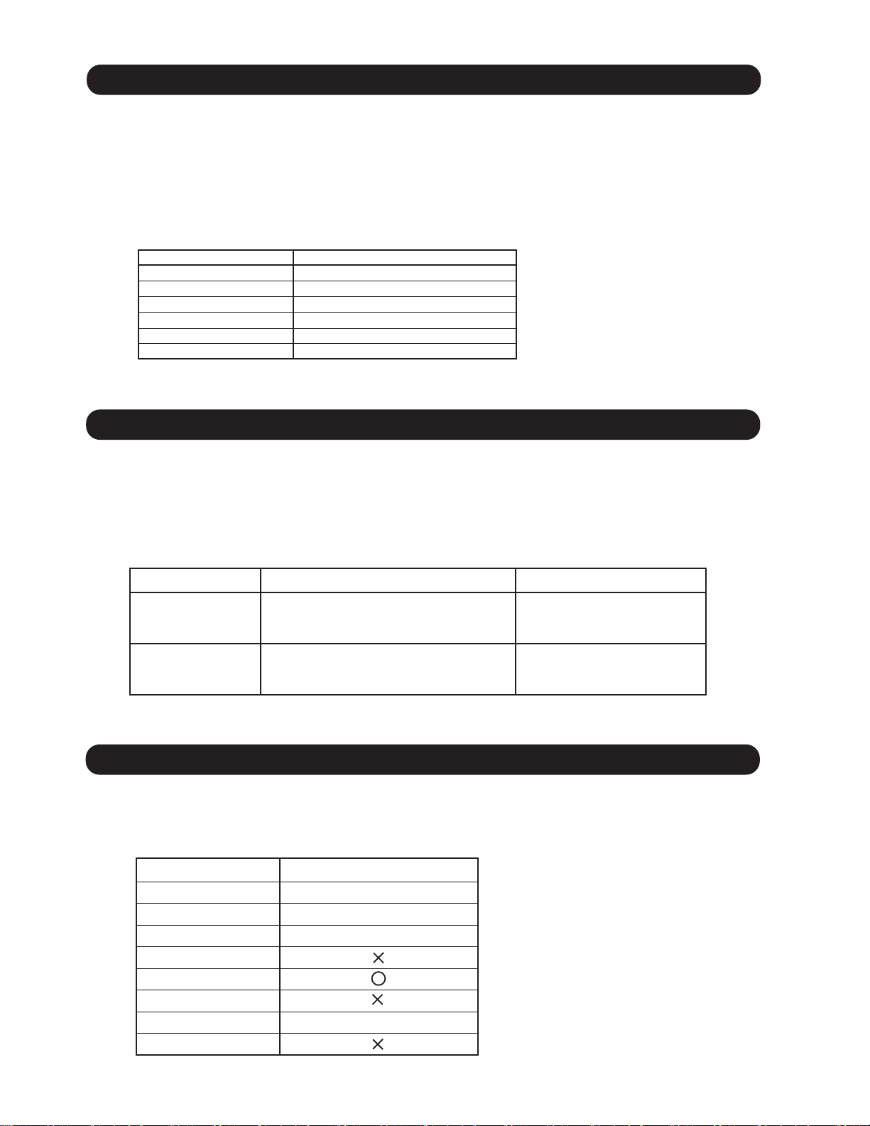
1-12. AUTO RESTART
When the power was interrupted by a power failure, etc. during operation, the operation contents
at that time are memorized and when power is recovered, operation is automatically resumed with
the memorized operation contents.
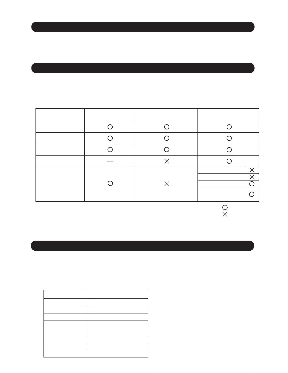
(Table 11 : Operation contents memorized when the power is interrupted)
Wireless remote controller
Wired remote controller
(When Memory Backup : Disable)
Wired remote controller
(When Memory Backup : Enable)
Operation mode
Set temperature
Set air flow
Thermistor detected position
OFF TimerON Timer
WEEKLY Timer
Timer mode
Temperature
SET BACK Timer
: Memorize
: Not memorize
*It is necessary to set on the DIP-SW1-No,6 of the wired remote controller, to enable the memory backup.
Refer to the installation manual of wired remote controller for details.
1-13. MANUAL AUTO OPERATION
If MANUAL / AUTO Button is pushed continuous from 3 seconds to 10 seconds,
manual auto operation will starts.
If the remote control is lost or battery power dissipated, this function will work without the remote
control.
(Table 12 : Manual auto operation control)
Functions
OPERATION MODE
SETTING TEMP.
FAN MODE
VERTICAL LOUVER
HORIZONTAL LOUVER
TIMER MODE
SWING OPERATION
ECONOMY
All models
Auto changeover
75.2°F(24°C)
Auto
NORMAL
NORMAL
Continuous
(No timer setting available)
OFF
OFF
01-20
1-14. FORCED COOLING OPERATION
Forced cooling operation is started when pressing MANUAL AUTO button for 10 seconds or more.
During the forced cooling operation, it operates regardless of room temperature sensor.
Operation LED and timer LED blink during the forced cooling operation. They blink for 1 second ON
and 1 second OFF on both operation LED and timer LED (same as test operation).
Forced cooling operation is released after 60 minutes of starting operation.
FORCED COOLING OPERATION will start as shown in Table12.
( Table 13 : Detail of forced cooling operation)
Forced cooling operation
OPERATION MODE
FAN CONT. MODE
TIMER MODE
SETTING TEMP.
SETTING LOUVER
SWING
Cooling
Hi
-
Room temperature is not controlled
Horizontal
OFF
1-15. COMPRESSOR PREHEATING
The compressor temperature is maintained more than ambient temperature (other refrigerant cycle parts)
for the following reasons.
⅙
⅙1.To Prevent the compressor damage by the cold start.
2.Speed up the ascent rate of the refrigerant, and the separation of the refrigerant and oil is furthered.
( Table 14 : Detail of compressor preheating operation )
Judgment condition Operation
Start condition
Outdoor temperature 89.6
and
>
°F (32°C)
=
Crankcase heater : ON
30 minutes after the compressor stop
Release condition
Outdoor temperature 93.2
Operating instruction to outdoor unit
>
°F (34°C)
=
or
Crankcase heater : OFF
1-16. MINIMUM HEAT OPERATION
MINIMUM HEAT OPERATION functions by pressing MIN HEAT button on the remote controller.
It is almost the same operation as below settings.
( Table 15 : Detail of MINIMUM HEAT OPERATION )
Operation mode
Setting temperature
Defrost operation
Oil recovery operation
Fan mode
Louver setting
Swing setting
LED indication
ON / OFF timer
Only ECONOMY LED (Green)
Heating
50°F (10°C)
Normal operation
Normal operation
01-21
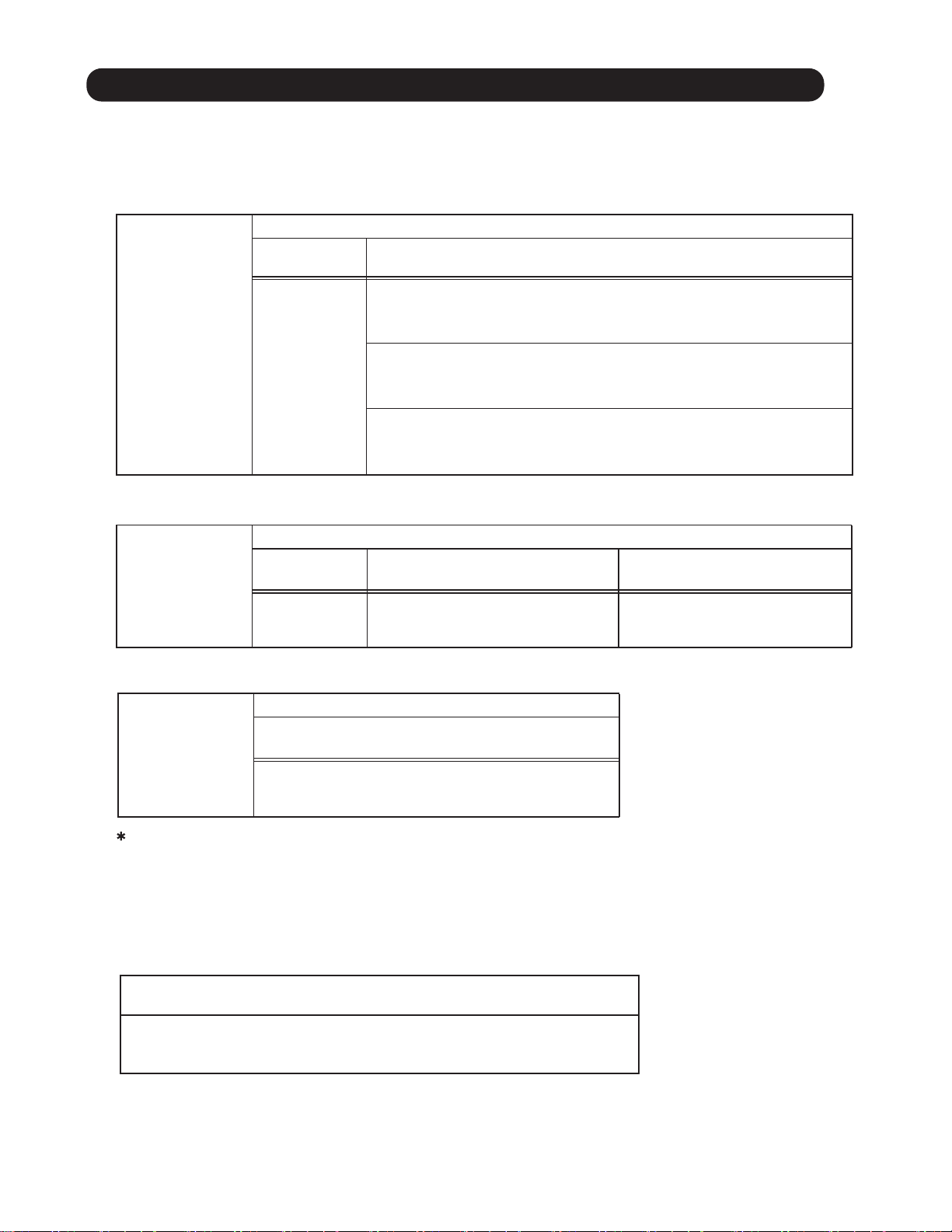
1-17. DEFROST OPERATION CONTROL
1. CONDITION OF STARTING THE DEFROST OPERATION
The defrost operation starts as shown in the following Table 16, 17 and 18.
( Table 16 : Condition of normal defrost operation)
Compressor integrating operation time
Less than
35 minutes
Does not operate
Normal defrost
Outdoor temperature 14°F (-10°C)
Heat exchanger temperature 23°F (-17°C )
Outdoor temperature 14°F (-10°C)
Heat exchanger temperature -14°F (7°C )
Over 35 minutes
>
=
and
>
and
<
=
<
=
and
>
<
=
Outdoor temperature 14°F (-10°C)
Heat exchanger temperature -4°F (-20°C )
( Table 17 : Condition of integrating defrost operation)
Compressor integrating operation time
Integrating defrost
Less than
210 minutes
Does not operate
Outdoor temperature 35.6°F (2°C)
Over 210 minutes
Compressor stop
and
<
=
Over 240 minutes
Outdoor unit
heat exchanger
temperature
<
26.6°F (-3°C)
=
( Table 18 : Condition of Integrating (OFF count) defrost operation)
Compressor continuous operation time
Integrating defrost
(OFF count defrost)
Less than 10 minutes
and
<
=
Outdoor temperature 35.6°F (2°C)
Compressor OFF count : 40 times
If any defrost operated, "compressor integrating operation time" and "compressor OFF count" are cleared.
2. CONDITION OF THE DEFROST OPERATION COMPLETION
Defrost operation is released when the conditions becomes as shown in Table 19.
( Table 19 : Condition of defrost release )
Release Condition
Outdoor heat exchanger temperature is higher than 53.6°F(12°C)
or
Compressor operation time has passed 15 minutes.
01-22
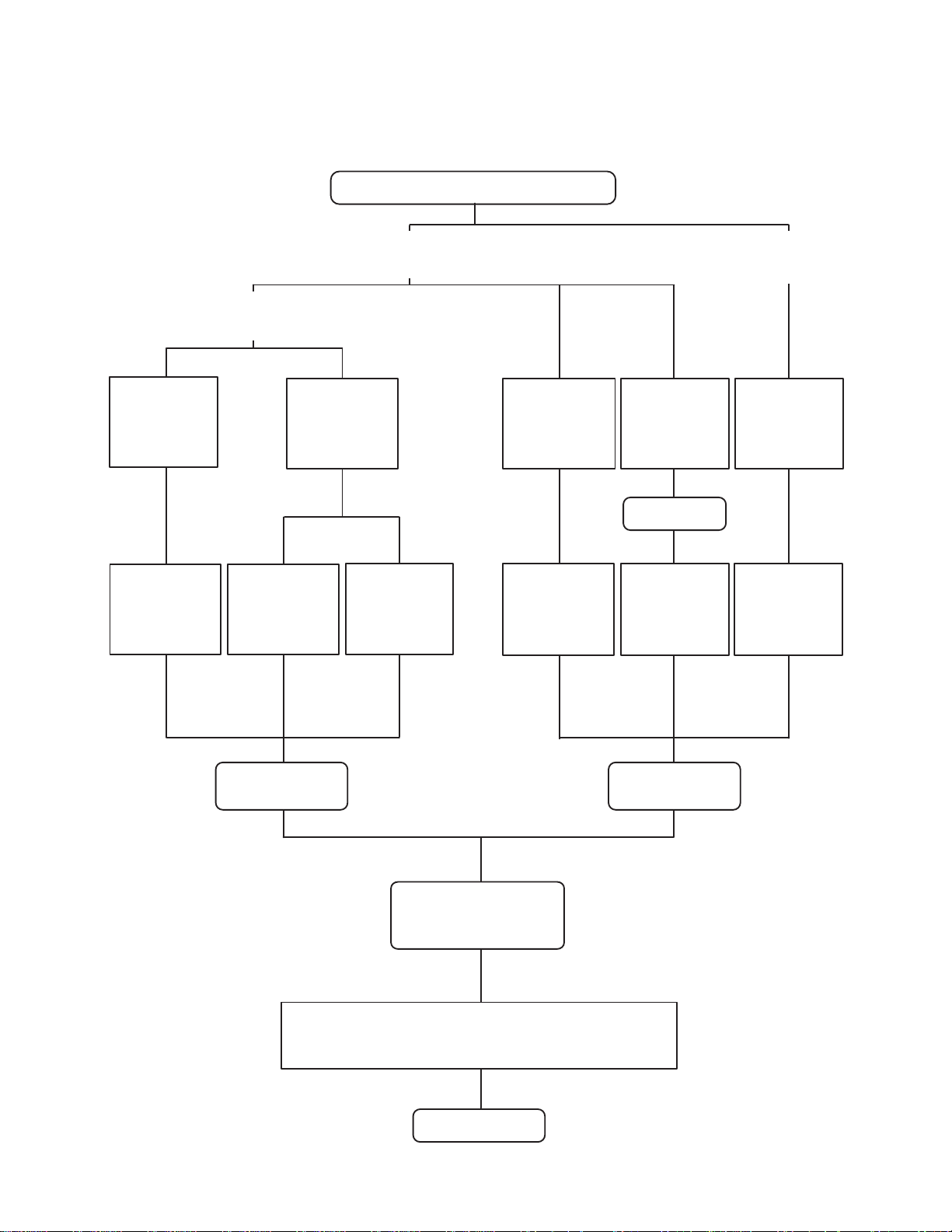
3. Defrost Flow Chart
The defrosting shall proceed by the integrating operation time, outdoor temperature
and outdoor heat exchanger temperature as follows.
Outdoor unit operation mode : Heating mode
Compressor integrating
Outdoor
temperature [Ta]
Ta > 14°F(-10°C)
=
Outdoor
heat exchanger
temperature [Tn]
Tn < 1.4°F(-17°C)
=
operation time :
Over 35 minutes
Outdoor
heat exchanger
temperature [Tn]
Tn < Ta - 14°F(7°C)
=
Compressor continuous
operation time
Over 10 minutes
Outdoor
temperature [Ta]
Ta < 14°F(-10°C)
Outdoor
heat exchanger
temperature [Tn]
Tn < -4°F(-20°C)
=
Compressor
integrating
operation time
Over 240 minutes
Outdoor
heat exchanger
temperature [Ta]
Below 26.6°F(- 3°C)
Compressor
integrating
operation time
Over 210 minutes
Compressor
stop
Outdoor
temperature [Ta]
Ta < 35.6°F(2°C)
Compressor continuous
operation time
Less than 10 minutes
Outdoor
temperature [Ta]
Ta < 35.6°F(2°C)
Compressor
OFF count
40 times
Normal defrost
start
Outdoor heat exchanger temperature (Outlet): Over 53.6° F(12°C)
Compressor : 70rps
Outdoor fan motor : OFF
Defrost Indicator:
[Operation lamp]
7 sec ON / 2 sec OFF
Main EEV : 480Pulse
4-way valve : OFF
Solenoid valve : OFF
Indoor fan : OFF
or
Compressor ON time: Maximum 15 minutes
Defrost end
01-23
Integrating defrost
start
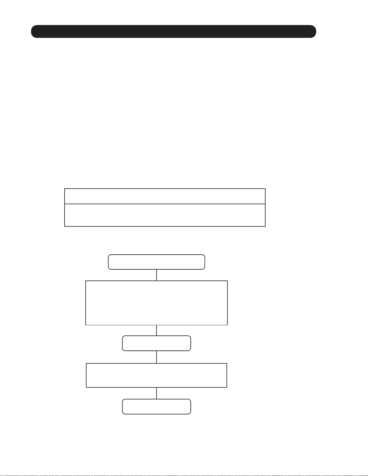
1-18. OFF DEFROST OPERATION CONTROL
When operation stops in the [Heating operation] mode, if frost is adhered to the outdoor unit heat
exchanger, the defrost operation will proceed automatically. In this time, the outdoor unit will allow
the heat exchanger to defrost, and then stop.
1. OFF DEFROST OPERATION CONDITION
When heating operation stops, all of following conditions are met, OFF defrost operation starts.
1. Compressor operation integrating time lasts for more than 30 minutes.
2. Compressor countinuous operation time lasts for more than 10 minutes.
3. Outdoor unit heat exchenger temperature is less than 24.8°F(-4°C).
If the operation stops in defrost operation, defrost operation is kept untill the it is completed.
2. OFF DEFROST RELEASE CONDITION
OFF defrost operation is released when the conditions becomes as shown in Table 31
( Table 20 : OFF Defrost Release Condition )
Release Condition
Outdoor heat exchanger temperature is higher than 53.6°F(12°C)
or
Compressor operation time has passed 15 minutes.
OFF Defrost Flow Chart
Heating operation stop
Compressor integrating operation : Over 30 minutes
and
Compressor countinuous operation time : Over 10 minutes
and
Outdoor heat exchanger temperature : Below
Defrost start
Outdoor heat exchanger temperature : Over 53.6°F(12°C)
or
Compressor ON time : Maximum 15 minutes
24.8°F(-4°C)
Defrost end
01-24
1-19. OIL RECOVERY OPERATION
Outdoor unit operates by cooling refrigerant cycle for recover the refrigerant oil to the compressor
1. Cooling oil recovery operation
< Start condition >
It operates forcibly from the compressor integrating time in Cooling and Dry mode.
Condition of the oil recovery operates after 1 hour
(1). First time after power ON
(2). When the operation mode changes from Heating to Cooling. (only first time)
Condition of the oil recovery operates after 3 hour
Without condition
< Operation >
Compressor : Over 50rps
Outdoor fan : Normal operation
4 way valve : OFF
< Release condition >
*2~7 minutes has passed from the start of oil recovery operation.
2. Heating oil recovery operation
< Start condition >
It operates forcibly when the compressor integrating operation time becomes 12 hours.
< Operation >
Refrigerant cycle is changed to the cooling cycle temporarily.
Compressor : Fixed 50rps
Outdoor fan : Step2 (290rpm)
4 way valve : OFF
< Release condition >
*1~5 minutes has passed from the start of oil recovery operation.
During the oil recovery operation, appears on the display of wired and central remote controller,
and appears on the simple remote controller.
The operation indicators (LED) of the indoor units flash slowly.
*Operation time changes from the progress status of oil recovery.
01-25
1-20. FRESH AIR CONTROL( For AU / AR type)
The fan motor for Fresh Air is operated in synchronization with the indoor fan operation
as shown in Figure 22.
(Fig. 22 : Fresh Air control)
Fan motor
(Indoor unit)
Fan motor
(for Fresh Air)
Operation
Stop
Operation
Stop
*It needs the external relay and power supply.
1-21. EXTERNAL ELECTRICAL HEATER CONTROL (For AR type)
The External Electrical Heater is operated as below.
< Heater : ON condition >
When all of the following conditions are met, external elecrtical heater will operate according to Figure 23.
System type
Operation mode
Compressor
Indoor fan
Heatpump
Heating
ON
ON (S-Lo is excluded)
< Heater : OFF condition >
1). When one of the ON conditions is not met.
2). When Defrost operation or Oil recovery operation starts
(Fig. 23 : External electrical heater control)
Heater : OFF
Ts -6°F(-3°C)
Ts -24°F(-12°C)
When the room
temperature drops
Heater : ON
Heater : OFF
When the room
temperature rises
Ts : Setting temperature
Ts -2°F(-1°C)
Ts -20°F(-10°C)
01-26
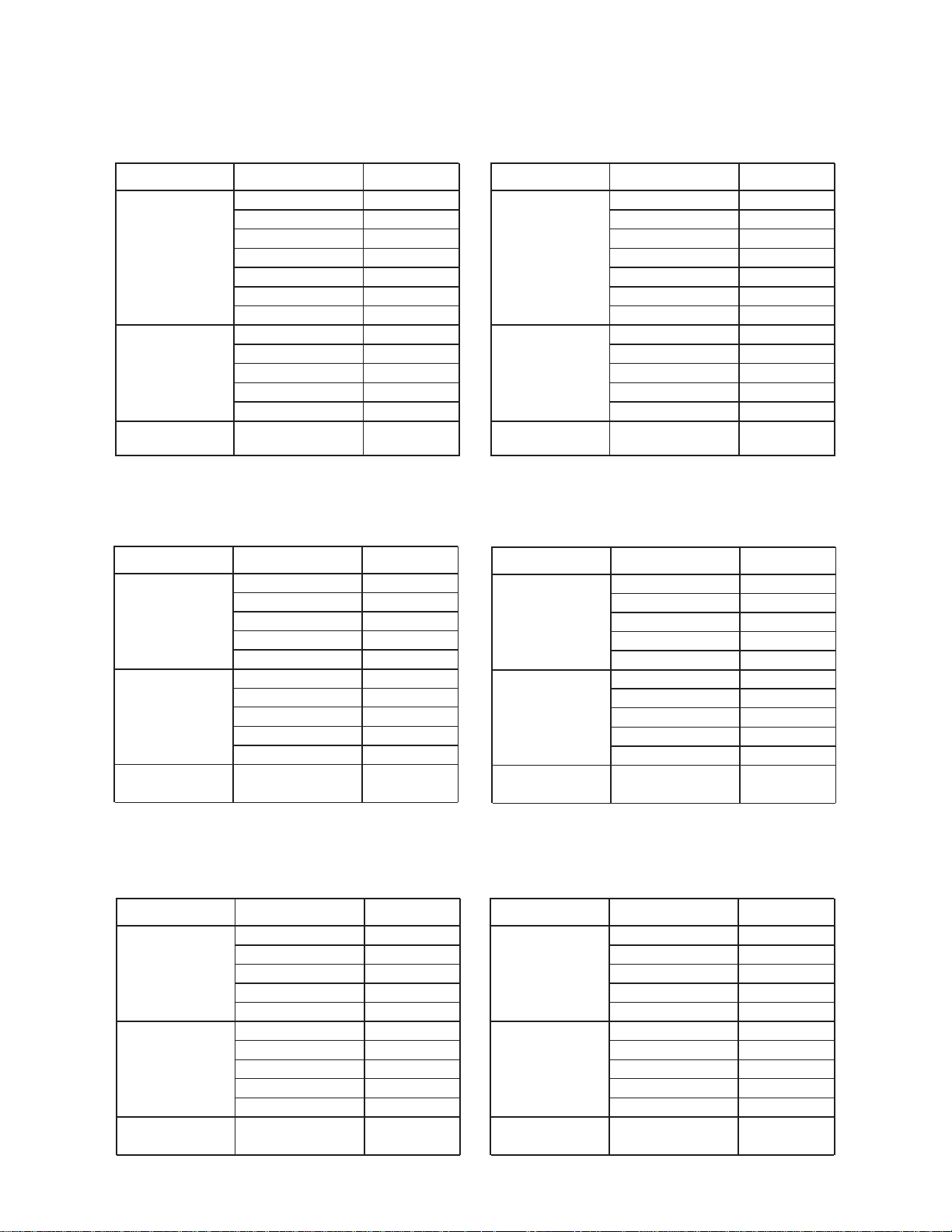
1-22. DRAIN PUMP OPERATION
During Cooling / Dry mode
1. When the compressor starts, the drain pump starts simultaneously.
2. The drain pump operates continuously for 3 minutes after the compressor is turned off.
3. When the compressor stops by the "Anti- freezing protection", the drain pump is turned off
in 1 hour after the compressor stops.
4. When the water level in the drain pan rises up and then the float switch functions:
1
The compressor, indoor and outdoor fan motor operation are stopped.
2
Drain pump operates continuously for 3 minutes after the float switch is turned off.
(Almost condensing water may be drained)
3
The indoor unit fan motor operates after the float switch is turned off.
5. When the float switch turns ON continuously for 3 minutes, "FAILURE INDICATION" operates.
(It is necessary to turn off power for release it. )
6. When the float switch turns OFF less than 3 minutes, the unit starts Cooling operation.
( Fig. 24 : Detail of Drain Pump Operation in Cooling / Dry )
Compressor
Drain Pump
ON
OFF
ON
OFF
3 minutes
<Float Switch turns OFF less than 3 minutes>
Less than 3 minutes
Float Switch
Compressor
Indoor Fan
Drain Pump
ON
OFF
ON
OFF
3 minutes ST
ON
OFF
ON
OFF
3 minutes
During HEATING / FAN mode / Stop operation
1.When the water level in the drain pan rises up and then the float switch functions:
Drain pump operates continuously for 3 minutes after the float switch is turned off.
1
(Almost condensing water may be drained)
2. When the float switch turns ON continuously for 3 minutes, "FAILURE INDICATION" operates.
Thereafter, even if the float switch turns OFF, the "FAILURE INDICATION" is not released.
(It is necessary to turn off power for release it. )
( Fig. 25 : Detail of Drain Pump Operation in Heating )
Float Switch
Drain Pump
ON
OFF
ON
OFF
01-27
3 minutes
 Loading...