


|
Operator'sManual |
Инструкцияпоэксплуатации |
|
MIG-MAG
Сварочный полуавтомат
MIG-MAG Welding machine
IRMIG 140
IRMIG 160
IRMIG 180
www.fubag.ru

Operator's manual
www.fubag.ru
WARNING! BEFORE USING THE WELDING MACHINE READ THE INSTRUCTION MANUAL CAREFULLY! FOR QUALIFIED AND SPECIALLY TRAINED PERSONS ONLY AFTER PROPER READING OF THIS MANUAL IS ALLOWED TO USE AND TO MAINTAIN THIS WELDING MACHINE.
The detailed description, safety rules and all required information necessary for proper operation and maintenance of FUBAG welding machine are provided below. Keep this instruction manual by machine and refer to it by any doubts concerning safety operation, maintenance storage and handling of FUBAG welding machine.
1.Safety operation
-It is highly recommended always to follow the safety rules. Wear protective clothes and special means to avoid injuries to eyes and skins.
-Use the welding mask or special protective glasses while working with the welding machine. Only by viewing through the filter lens on the welding mask your eyes are secured by your operation.
-Prevent the sparks and spatter from harming your body.
-Under no circumstance allow any part of your body to touch the welder's output bipolarity (torch and work piece).
-Do not operate under water or more humid place.
-Fumes and gases produced when welding are hazardous to health. Make sure to work in places where there are exhaust or ventilation facilities to keep fumes or emissions away from the breathing zone.
-Please remember to keep arc rays away from the other nearby people when welding. This is only due to the interference from arc rays.
-There will be high temperature when welding work piece, so please don't directly touch on it
-No touching on the output connection or any other electrification parts while welding.
-No touching on the electrification parts after turning on the power. Cut off the power supply after operation or before leaving the welding site.
-No welding in the dangerous site where easily get an electrical shock.
-No welding for the container loaded inflammable or explosive materials.
-Safe measures should be adoptted while operating in high place to avoid accident.
-No entering the welding site for persons not concerned.
-Welders possible have electromagnetism and frequency interference, so keep away people with heart pace or the articles which can be interfered by electromagnetism and frequency.
WARNING. The welder voltage is always higher, so the safety precaution should be taken before repair to avoid accidental shock. Switch off the power supply before each type of maintenance work. The untrained people are not allowed to make maintenance of the machine.
- 1 -

Operator's manual
www.fubag.ru
-Check the connection of input and output cables and the earth (ground) connection, etc.
-Maintenance should be conducted by the trained personnel.
-The newly installed machine or the welder not in use for some time needs to be checked by multimeter have the right insulation resistance between each winding and the case.
-When the welder is used outdoors, it should be kept from rain or long exposure to the sun.
-Check is needed from time to time to make sure the welding cable is in good condition if the welding machine is in frequent use. Check at least once each month if the welder is in regular use. It is necessary to check when the welder is in mobile use.
-If the welder is not in use either for a long time or temporarily, it should be kept dry and have good ventilation to free it from moisture, erodible or toxic gas.
-The welder must be installed in the place where it can not be exposed to sun and rain. Also it
must be stored in less humid place with the temperature range at -10 +40OC.
-Dust removal is needed every year. Check the machine's fasteners, moving-iron, current regulation screws, etc to make sure there are no loose connection problems.
-The dust, acid and erodible dirt in the air at the job site can not exceed the amount required by the norm (excluding the emission from the welder).
-The welder must be installed in the place where it can not be exposed to sun and rain. Also it must be stored in less humid place with the temperature.
-There should be 50 cm space about for the welding machine to have good ventilation.
-Make sure that there is no metal-like foreign body to enter the welding machine.
-Electrode must be taken down from holder when no welding.
-No violent vibration in the welder's surrounding area.
-Make sure that there is no interference with the surrounding area at the installation site.
-The welder should be installed on the horizontal surface and if it over 15°, there should be added some anti-dump set.
-Take measures to prevent wind while operating in the strong wind since the welder is gas shielded. The wind speed is limited below 1,0 m/s, or the wind shield device must be loaded.
Safety Check:
Each item listed below must be carefully checked before operation:
-Make sure that there is no short circuit connection with welder's both outputs.
-Make sure that there is always sound output and input wire connection instead of exposing it outside.
Regular check needs to be conducted by the qualified personnel after the welding machine has been installed over a long period or re-operation, which involves as follows:
-Check the welding cable to see if it can continue to be used before it is worn out.
-Replace the welder's input cable as soon as it is found to be broken or damaged.
-Make sure whether there is enough power supply to make the welding machine work properly. Any power source required to access the welding machine must be installed with some protective equipments.
Please do not hesitate to contact us for technical assistance whenever you come across the problems you can not work out or you may deem difficult to fix.
- 2 -

Operator's manual
www.fubag.ru
2. Technical Specification
Item |
IRMIG140 |
IRMIG160 |
IRMIG180 |
Rated input voltage, V |
|
220 |
|
Frequency, Hz |
|
50 |
|
Rated input current, А |
25 |
28 |
30 |
Rated input, kVA |
5,5 |
6,2 |
6,6 |
Rated no-load voltage, V |
52 |
52 |
52 |
MIG min welding current, А |
30 |
30 |
30 |
MIG max welding current, А |
140 |
160 |
180 |
MIG rated duty cycle, % |
35 |
30 |
25 |
MIG welding current at 100%, А |
83 |
88 |
90 |
Efficiency, % |
85 |
85 |
85 |
Power factor |
0,92 |
0,92 |
0,75 |
Insulation class |
|
H |
|
Enclosure protection |
|
IP21S |
|
Cooling type |
|
Fan cooled |
|
Dimension (LхWхH), mm |
|
570x300x370 |
|
Weight, kg |
11 |
11 |
12 |
The manufacturer reserves himself the right to make the manual's content or welder's function change without any preliminary notification of the users.
3. Description
MIG Series Inverter is designed to be used with the advanced IGBT (Insulated Gate Bipolar Tube) and rapid recovery diode as its main control and transfer components and assisted with the specially developed control circuit. The continuous wire can form welding seam metal after melting so as to connect the wok pieces each other. The melting electrode gas protects the welding district easily, so it is easy to operate & observe the whole working process. Its characteristics are high produce efficiency and easy to carry out all-position welding.
The highlighted characteristics of MIG Series Inverter:
-Featured with small volume and light weight, it widely used in upholstering field, repairing field and fieldwork.
-High working efficiency. Automatic Wire Feeding can realize high speed welding.
-No special requirements for the welding wire. Both solid and flux-cored wires are available. The diameter of the wire is between 0,6 - 0,8 (1,0) mm.
-Undercutfunction make arc-piloting more successful.
- 3 -
Operator's manual
www.fubag.ru
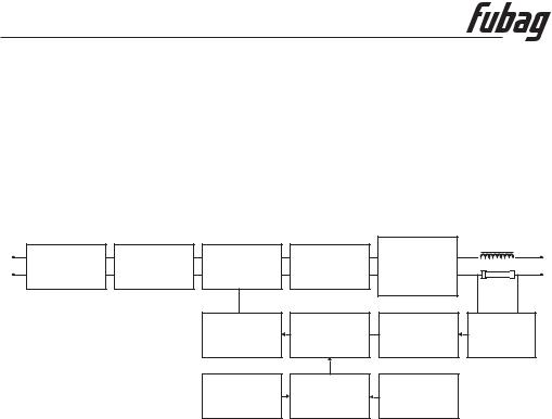
4. Welder’s Principle
The welder acquires 220V single phase industrial frequency DC power source through the power switch and rectify through single phase rectifier bridge and then filtered through capacitor to get the DC current. The 40 KHz AC current is got through the IGBT all-bridge inverter. Then this alternating current, transformed by the intermediate frequency transformer and rectified by quick recovery diode, outputs the stable direct current for the welder immediately after it has been filtered by the reactor. The wire feed speed can be stepless adjusted through the speed adjust knob. The welding current is easily influenced from the wire feed speed, usually the faster the wire feed speed the bigger the Amp value under the same voltage.
|
|
Inverter |
|
High |
|
Rectifier |
Filter |
Transformation |
Frequency |
|
|
Function |
|
||||
|
|
|
Rectifier |
|
|
|
|
|
|
|
|
|
|
Drive |
Modulate |
Trait |
Sampling |
|
|
Control |
|||
|
|
|
|
|
|
|
|
Protection |
Process |
Current |
|
|
|
Inspect |
Control |
Adjustment |
|
MIG series use the movable carton like structures: The upper part in the front is equipped with a welding current regulation knob, abnormal indicator light, working indicator. The back side is installed with power switch, gas valve connection , cooling fan, power source lead-in wire, breaker. On the top there is a handle for the convenient of easy transport. When you open the cover, there is one primary transformer, one piece of printed circuit board. The bottom part is supplied with output reactor, primary transformer and etc. Installed in the middle part is a radiator with power elements.
Environment to Which the Product Is Subject:
-The surrounding temperature range: when welding: -10 + 40ОС; During transport or in storage: -25 +55ОС
-Relative humidity: when at 40ОС: ≤50%, when at 20ОС: ≤ 90%
-The dust, acid and erodible materials in the air can not exceed the amount required by the norm (apart from the emissions from the welding process). No violent vibration at the job site.
-Keep from raining when it is used outdoor.
-Altitude no more than 1,000m.
Requirement for Main Supply:
- The oscillation of the supplied voltage should not exceed ±10% of the rated value.
- 4 -
Operator's manual
www.fubag.ru
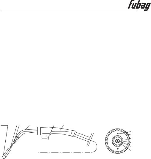
5. Torch
The torch is composed by torch stand, connecting cable and handle. Torch stand is the interface of torch and wire feeding device.
Connecting cable: covered by nylon pipe the liner is loaded in the center of coreless cable. The inner part of liner is the passage for wire feeding. The space between liner and coreless cable is the passage for shielded gas. Coreless cable is the passage for current.
There is a gooseneck installed in the handle of the torch. In the back part of the torch there is a connecting with the coreless cable and in the front part is a shunt. The shielded gas distributes via the shunt and forms well-proportioned air current in the nozzle, and then spurt out in a form of air hanging. Set with a sensitive switch on the handle to control the welding current.
Notice:
-Must cut off the power before assemble/disassemble torch or replace the components.
-The nozzle must be replaced in time on the condition that welding quality was influenced when it burned to some extent. The distributor of torch must be replaced when it ruined.
-The cable of torch must be replaced when it worn out.
NOZZLE CONTACT SHUNT GOOSENECK |
SWITCH HANDLE |
TIP |
|
|
RUBBER LAYER |
|
CONTROL CABLE |
|
CORELESS CABLE |
|
NYLON PIPE |
|
SPRING PIPE |
|
WIRE |
- 5 -
Operator's manual
www.fubag.ru
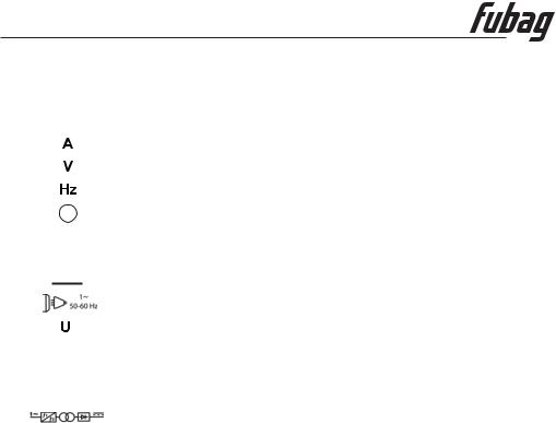
6. Sign & Pictures Illustration
|
SIGN |
NAME |
||||||
|
|
|
|
|
|
|
|
Current |
|
|
|
|
|
|
|
|
|
|
|
|
|
|
|
|
|
Power |
|
|
|
|
|
|
|
|
|
|
|
|
|
|
|
|
|
Frequency |
|
|
|
|
|
|
|
|
|
|
|
|
|
|
|
|
|
Ground |
|
|
|
|
|
|
|
|
|
|
|
|
|
|
|
|
|
|
|
|
|
|
|
|
|
|
|
|
|
H |
Insulation grade |
|||||
|
|
|
|
|
|
|
|
|
|
|
|
|
|
|
|
|
|
IP21 |
Protection class |
|||||||
|
|
|
|
|
|
|
|
DC current |
|
|
|
|
|
|
|
|
|
|
|
|
|
|
|
|
|
|
|
|
|
|
|
|
|
|
Power source |
|
|
|
|
|
|
|
|
|
0 |
|
Rated open circuit voltage |
||||||
|
|
|||||||
|
|
|
|
|
|
|
|
|
|
|
X |
Duty cycle |
|||||
|
|
|
|
|
|
|
|
|
|
|
|
I 1 |
Rated input current |
||||
|
|
|
I 2 |
Rated welding current |
||||
|
|
|
|
|
|
|
|
Welder’s structure |
|
|
|
|
|
|
|
|
|
|
|
U1 |
Rated input voltage |
|||||
|
|
|
|
|
|
|
|
|
|
|
|
|
|
|
|
|
|
|
|
U2 |
Rated load voltage |
|||||
|
|
|
|
|
|
|
|
|
7. Installation
Welder’s Placement
-The dust, acid and erosible dirt in the air at the job site can not exceed the amount required by the norm.
-The welder must be installed in the place where it can not be exposed to sun and rain. Also it
must be stored in less humid place with the temperature range at -10 до 40ОС.
-There should be 50 cm space about for the welding machine to have good ventilation.
-Apparatus to exclude wind and smoke should be equipped if the inside aeration is not sound.
- 6 -

Operator's manual
www.fubag.ru
POWER INPUT CABLE

GAS
FLOWMETER
СО2 |
GAS PIPE |
TORCH
TORCH SWITCH
WORK |
GROUNDING |
PIECE |
CABLE |
Connection between Welder and Power Source
Connect the power source cable at the back board of the welder into the single phase 220 voltage power network with breaker; 380 voltage power sources is strictly prohibited to the welder which will severely damage the welder, otherwise the user should take the consequences for it.
Notice: The melting current of the fuse is 1.2~1.5 times of its rated current.
1-phaze power supply 220 V
Input connection Sketch
Item |
IR 140/160 |
IR 180/200 |
Circuit breaker, А |
≥40 |
≥45 |
Fuse (Rated current), А |
30 |
40 |
Knife Switch, А |
35 |
45 |
Power cord, мм2 |
≥2,5 |
≥2,5 |
The installation and connection of MIG Welding
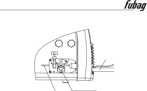
Connection and installation of the wire feeder
-Select suitable wire according to welding technology. The wire diameter must be matched with drive roll, wire guide pipe liner and contact tip.
-Open the lid of wire reel on the wire feeder put “Wire Coil” into “Wire Reel” on the wire feeder. Attention: Wire end under the “Wire Reel”, opposite wire feeder.
-There is damping screw device in the “Wire Reel” (hex head screw will be seen when open the lid). Pull the wire reel with hand when adjust. If resistance is over large, may adjust damping bolt: screw clockwise will enlarge the value and vice versa.
-7 -
Operator's manual
www.fubag.ru
TORCH
WIRE |
FEED |
|
ROLLER |
-Lead wire into “Wire Guide Pipe” of wire feeder, align wire with roll groove through “Drive Roll”, re-lead “Socket Tip” and press “Drive Roll”. (If more welding wire is needed, it will be done after switching on the power.)
Connection of the Connection Cable
-Connect the copper tip of the earth clamp which thread through the wire access hole on the panel with “-“ of the “connecting tip”. The connecting cable must be reliable, or the connecting tip will burn out.
-In order to reach sound performance when welding with flux-cord wire, it’s available that connect the “+”, “-” in an opposite way, that’s the wire feed motor with “-“and the connecting cable with “+”. Notice: Do not use steel plate or the materials alike which are ill conductor to connect between welder and work piece.
- 8 -
 Loading...