


www.iconfitness.com
Model No. SFTL18909.0 Serial No.
Write the serial number in the space above for reference.
Serial
Number
QUESTIONS? Decal
If you have questions, or if parts are damaged or missing, DO NOT
CONTACT THE STORE; please contact Customer Care. IMPORTANT: Please register this product (see the limited warranty on the back cover of this manual) before contacting Customer Care.
1CALL-866TOLL-362-FREE:-4490
Mon.–Fri. 6 a.m.–6 p.m. MT
Sat. 8 a.m.–4 p.m. MT
ON THE WEB:
www.iconservice.com
CAUTION
Read all precautions and instructions in this manual before using this equipment. Save this manual for future reference.
USER'S MANUAL
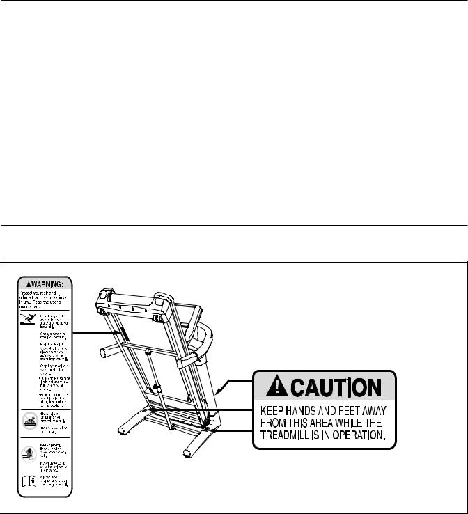
TABLE OF CONTENTS
WARNING DECAL PLACEMENT . . . . . . . . . . . . . . . . . . . . . . . . . . . . . . . . . . . . . . . . . . . . . . . . . . . . . . . . . . . . . .2 IMPORTANT PRECAUTIONS . . . . . . . . . . . . . . . . . . . . . . . . . . . . . . . . . . . . . . . . . . . . . . . . . . . . . . . . . . . . . . . . .3 BEFORE YOU BEGIN . . . . . . . . . . . . . . . . . . . . . . . . . . . . . . . . . . . . . . . . . . . . . . . . . . . . . . . . . . . . . . . . . . . . . . .5 ASSEMBLY . . . . . . . . . . . . . . . . . . . . . . . . . . . . . . . . . . . . . . . . . . . . . . . . . . . . . . . . . . . . . . . . . . . . . . . . . . . . . . .6 OPERATION AND ADJUSTMENT . . . . . . . . . . . . . . . . . . . . . . . . . . . . . . . . . . . . . . . . . . . . . . . . . . . . . . . . . . . .12 HOW TO FOLD AND MOVE THE TREADMILL . . . . . . . . . . . . . . . . . . . . . . . . . . . . . . . . . . . . . . . . . . . . . . . . . .20 TROUBLESHOOTING . . . . . . . . . . . . . . . . . . . . . . . . . . . . . . . . . . . . . . . . . . . . . . . . . . . . . . . . . . . . . . . . . . . . . .21 EXERCISE GUIDELINES . . . . . . . . . . . . . . . . . . . . . . . . . . . . . . . . . . . . . . . . . . . . . . . . . . . . . . . . . . . . . . . . . . .24 PART LIST . . . . . . . . . . . . . . . . . . . . . . . . . . . . . . . . . . . . . . . . . . . . . . . . . . . . . . . . . . . . . . . . . . . . . . . . . . . . . . .25 EXPLODED DRAWING . . . . . . . . . . . . . . . . . . . . . . . . . . . . . . . . . . . . . . . . . . . . . . . . . . . . . . . . . . . . . . . . . . . . .27 ORDERING REPLACEMENT PARTS . . . . . . . . . . . . . . . . . . . . . . . . . . . . . . . . . . . . . . . . . . . . . . . . . .Back Cover LIMITED WARRANTY . . . . . . . . . . . . . . . . . . . . . . . . . . . . . . . . . . . . . . . . . . . . . . . . . . . . . . . . . . . . . . .Back Cover
WARNING DECAL PLACEMENT
This drawing shows the locations of the warning decals. If a decal is missing or illegible, call the telephone number on the front cover of this manual and request a free replacement decal. Apply the decal in the location shown. Note: The decals may not be shown at actual size.
FREEMOTION is a registered trademark of ICON IP, Inc.
2

IMPORTANT PRECAUTIONS
WARNING: To reduce the risk of serious injury, read all important precautions and inctions in this manual and all warnings on your treadmill before using your treadmill. ICON assumes no responsibility for personal injury or property damage sustained by or through the use of
this product.
1. Before beginning this or any exercise program, consult your physician. This is especially important for persons over age 35 or persons with pre-existing health problems.
2. It is the responsibility of the owner to ensure that all users of this treadmill are adequately informed of all warnings and precautions.
3. Use the treadmill only as described.
4. Place the treadmill on a level surface, with at least 8 ft. (2.4 m) of clearance behind it and 2 ft. (0.6 m) on each side. Do not place the treadmill on any surface that blocks air openings. To protect the floor or carpet from damage, place a mat under the treadmill.
5. Keep the treadmill indoors, away from moisture and dust. Do not put the treadmill in a garage or covered patio, or near water.
6. Do not operate the treadmill where aerosol products are used or where oxygen is being administered.
7. Keep children under age 12 and pets away from the treadmill at all times.
8. The treadmill should be used only by persons weighing 350 lbs. (159 kg) or less.
9. Never allow more than one person on the treadmill at a time.
10. Wear appropriate exercise clothes when using the treadmill. Do not wear loose clothes that could become caught in the treadmill. Athletic support clothes are recommended for both men and women. Always wear athletic shoes. Never use the treadmill with bare feet, wearing only stockings, or in sandals.
3

18.The treadmill is capable of high speeds. Adjust the speed in small increments to avoid sudden jumps in speed.
19.The pulse sensor is not a medical device. Various factors, including the user's movement, may affect the accuracy of heart rate readings. The pulse sensor is intended only as an exercise aid in determining heart rate trends in general.
20.Never leave the treadmill unattended while it is running. Always remove the key, unplug the power cord, and switch the reset/off circuit breaker to the “off” position when the treadmill is not in use. (See the drawing on page 5 for the location of the reset/off circuit breaker.)
21.Do not attempt to raise, lower, or move the treadmill until it is properly assembled. (See ASSEMBLY on page 6, and HOW TO FOLD AND MOVE THE TREADMILL on page 20.) You must be able to safely lift 45 lbs. (20 kg) to raise, lower, or move the treadmill.
22.Do not change the incline of the treadmill by placing objects under the treadmill.
23. Inspect and properly tighten all parts of the treadmill regularly.
24. Never insert or drop any object into any DANGER:opening on the treadmill.
25. Always unplug the power cord immediately after use, before cleaning the treadmill, and before performing the maintenance and adjustment procedures described in this manual. Never remove the motor hood unless instructed to do so by an authorized service representative. Servicing other than the procedures in this manual should be performed by an authorized service representative only.
26.The treadmill is intended for in-home use only. Do not use the incline trainer in any commercial, rental, or institutional setting.
27.Over exercising may result in serious injury or death. If you feel faint or if you experience pain while exercising, stop immediately and cool down.
This equipment has been tested and found to comply with the limits for a Class B digital device, pursuant to part 15 of the FCC Rules. These limits are designed to provide reasonable protection against harmful interference in a residential installation. This equipment generates, uses, and can radiate radio frequency energy and, if not installed and used in accordance with the instructions, may cause harmful interference to radio communications. However, there is no guarantee that interference will not occur in a particular installation. If this equipment does cause harmful interference to radio or television reception, which can be determined by turning the equipment off and on, the user is encouraged to try to correct the interference by one or more of the following measures:
•Reorient or relocate the receiving antenna.
•Increase the separation between the equipment and the receiver.
•Connect the equipment into an outlet on a circuit different from that to which the receiver is connected.
•Consult the dealer or an experienced radio/TV technician for help.
WARNING: Per FCC rules, changes or modifications not expressly approved by ICON could void the user's authority to operate the equipment.
SAVE THESE INSTRUCTIONS
4
BEFORE YOU BEGIN
Thank you for selecting the revolutionary FREEMOTION® XTR treadmill. The XTR treadmill offers an impressive selection of features designed to make your workouts at home more enjoyable and effective. And when youʼre not exercising, the unique treadmill can be folded up, requiring less than half the floor space of other treadmills.
For your benefit, read this manual carefully before using the treadmill. If you have questions after read-
ing this manual, please see the front cover of this manual. To help us assist you, note the product model number and serial number before contacting us. The model number and the location of the serial number decal are shown on the front cover of this manual.
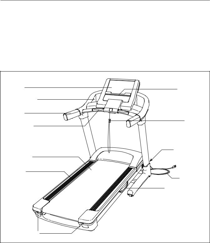
Before reading further, please look at the drawing below and familiarize yourself with the labeled parts.
Console |
Book Holder |
|
|
Accessory Tray |
|
Handrail |
|
Pulse Sensor |
Key/Clip |
|
|
|
Reset/Off |
|
Circuit Breaker |
Walking Belt |
|
Foot Rail |
Power Cord |
|
|
|
Adjustable Cushion |
Idler Roller |
|
Adjustment Bolts |
|
|
5 |
ASSEMBLY
To hire an authorized service technician to assemble the treadmill, call 1-800-445-2480. To watch a video demonstration of the assembly procedure, go to www.freemotionfitness.com/assembly. Assembly requires two persons. Set the incline trainer in a cleared area and remove all packing materials. Do not dispose of the packing materials until assembly is completed. Note: The underside of the incline trainer walking belt is coated with high-performance lubricant. During shipping, some lubricant may be transferred to the top of the walking belt or the shipping carton. This is normal and does not affect performance. If there is lubricant on top of the walking belt, simply wipe off the lubricant with a soft cloth and a mild, non-abrasive cleaner.
Assembly requires the included hex keys and your own Phillips screwdriver and adjustable wrench 
 .
.
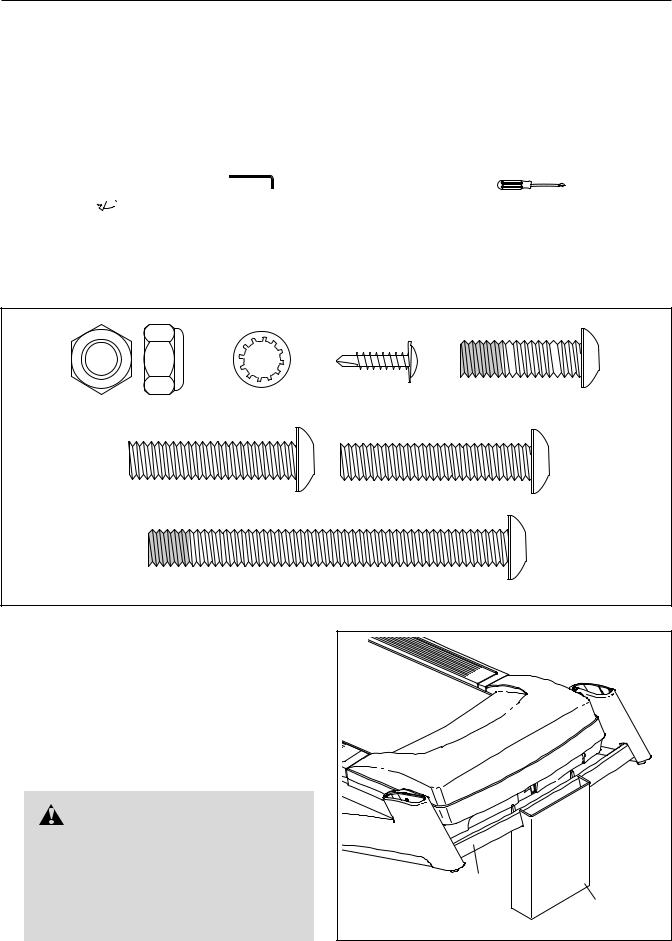
Use the drawings below to identify the assembly hardware. The number in parentheses below each drawing is the key number of the part, from the PART LIST near the end of this manual. The number after the parentheses is the quantity needed for assembly. Note: If a part is not in the hardware kit, check to see if it is preattached to one of the parts to be assembled. To avoid damaging plastic parts, do not use power tools for assembly.
3/8" Jam Nut (7)–2 |
3/8" Star Washer |
#8 x 3/4" |
3/8" x 1 1/4" |
Tek Screw (24)–4 |
Patch Bolt (2)–6 |
||
|
(6)–10 |
|
|
3/8" x 1 3/4" Bolt (3)–1 |
3/8" x 2" Bolt (4)–1 |
||
|
3/8" x 3 3/4" Patch Bolt (5)–4 |
|
|
1. Make sure that the power cord is unplugged. |
1 |
|
|
|
|
With the help of a second person, raise the front |
|
|
of the treadmill and insert the crossbar on the |
|
|
Base (103) into the cutout in the cardboard |
|
|
stand as shown. Have the second person hold |
|
|
the treadmill to prevent it from moving for- |
|
|
ward or backward until assembly step 3 is |
|
|
completed. |
|
|
WARNING: Serious injury |
|
|
y occur if the treadmill moves for- |
|
|
ward or backward and falls off the card- |
|
|
board stand. A second person must |
103 |
|
hold the treadmill until assembly step 3 |
|
|
is completed to prevent the treadmill |
|
Cardboard |
from moving, tipping, or falling. |
|
Stand |
|
6 |
|
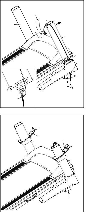
2. Identify the Right Upright (92) which is marked |
2 |
|
|
|
|
with a “Right” sticker. |
|
|
|
|
|
|
|
Wire |
|
|
|
Have a second person hold the Right Upright |
|
|
|
|
|
|
|
Tie |
93 |
|
|
(92) near the Right Base Cover (102). See the |
|
|
|
|
|
inset drawing. Tie the wire tie in the lower end |
|
91 |
|
|
|
of the Right Upright securely around the end of |
|
|
|
|
|
the Upright Wire (93). Then, pull the other end |
|
|
|
|
|
of the wire tie up through the top of the Right |
|
|
|
|
92 |
Upright until the Upright Wire is routed com- |
|
|
|
|
|
pletely through the Right Upright. |
|
|
|
|
|
Gently pull up on the Upright Wire (93) as you |
|
|
|
|
|
set the Right Upright (92) on the Base (103) in- |
|
|
|
|
102 |
side the Right Base Cover (102). Be careful not |
|
|
|
|
103 |
to pinch the Upright Wire. |
|
|
|
|
|
|
|
|
|
|
|
Attach the Right Upright (92) to the Base (103) |
|
|
|
|
|
with two 3/8" x 3 3/4" Patch Bolts (5) and two |
|
|
|
|
6 |
3/8" Star Washers (6). Note: It may be neces- |
|
|
|
|
|
sary to tip the top of the Right Upright forward |
|
|
|
|
|
slightly as you thread the Patch Bolts into it. Do |
|
|
|
|
5 |
not tighten the Patch Bolts yet. |
92 |
93 |
|
|
|
Attach the Left Upright (91) in the same way. |
|
|
|
||
|
|
|
|
||
|
Wire |
|
|
|
|
Note: There are no wires on the left side. |
|
|
|
|
|
|
Tie |
|
|
|
|
|
|
|
|
|
|
3. With the help of a second person, lower the |
3 |
|
|
|
|
treadmill off the cardboard stand. The stand will |
|
|
|
|
|
|
|
|
|
|
|
be used again in assembly step 9. |
|
|
|
89 |
|
Identify the Right Upright Sleeve (90) and the |
|
91 |
|
|
|
|
|
“Left” |
|
||
Left Upright Sleeve (89); the Upright Sleeves |
|
|
|
“Right” |
|
are labeled “Right” and “Left.” Slide the Right |
|
|
|
|
|
Upright Sleeve onto the Right Upright (92) and |
|
|
|
|
90 |
the Left Upright Sleeve onto the Left Upright |
|
|
|
|
|
(91). |
|
|
|
|
|
|
|
|
|
|
92 |
|
|
|
|
|
Cardboard |
|
|
|
|
|
Stand |
|
7 |
|
|
|
|
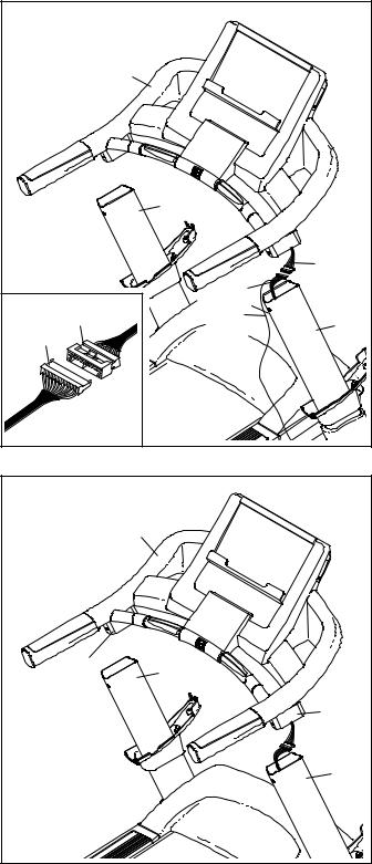
4.Have a second person hold the console assembly near the Uprights (91, 92).
Connect the Upright Wire (93) to the Console Wire (114). See the inset drawing. The connectors should slide together easily and snap into place. If they do not, turn one connector and try again. IF THE CONNECTORS
ARE NOT CONNECTED PROPERLY, THE CONSOLE MAY BE DAMAGED WHEN THE POWER IS TURNED ON. Remove the wire tie from the Upright Wire. Insert the connectors down into the Right Upright (92).
5.Next, insert the brackets on the Handrail (110) into the Uprights (91, 92). Make sure that no wires are pinched.
4 |
|
|
|
|
|
|
Console |
|
|
|
|
Assembly |
|
|
|
|
|
91 |
|
|
|
|
|
114 |
|
|
|
93 |
|
|
93 |
114 |
Wire |
92 |
|
|
Tie |
|
|
5 |
|
Console |
|
|
|
|
|
|
|
|
|
Assembly |
|
|
|
|
110 |
91 |
|
|
|
|
|
|
|
|
|
|
110 |
|
|
|
|
92 |
8
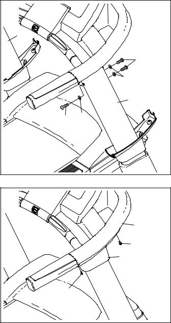
6. Partially tighten three 3/8" x 1 1/4" Patch Bolts |
6 |
|
(2) with three 3/8" Star Washers (6) into the |
|
|
Right Upright (92); do not fully tighten the |
|
|
Patch Bolts yet. |
91 |
|
Repeat this step with the Left Upright (91). |
|
|
|
|
|
Then, firmly tighten all six 3/8" x 1 1/4" Patch |
|
2 |
Bolts (2). |
|
|
|
|
6 |
|
|
92 |
|
2 |
6 |
7. Slide the Right Upright Sleeve (90) up against |
7 |
|
the console assembly. Attach the Right Upright |
|
|
Sleeve with two #8 x 3/4" Tek Screws (24). |
|
|
Attach the Left Upright Sleeve (not shown) to |
|
Console |
|
Assembly |
|
the console assembly in the same way. |
|
|
|
|
|
|
|
90 24 |
|
24 |
|
9
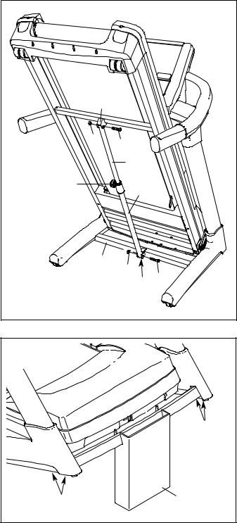
8. |
Orient the Storage Latch (87) so that the large |
8 |
|
|
|
|
|
|
|
barrel and the Latch Knob (88) are in the posi- |
|
|
|
|
|
|
|
|
|
|
|
|
|
|
|
|
|
tions shown. |
|
|
|
|
|
|
|
|
Remove the tie from the upper end of the |
|
|
|
|
|
|
|
|
Storage Latch (87). Attach the upper end of the |
|
|
|
|
|
|
|
|
Storage Latch to the bracket on the Frame (67) |
|
|
|
|
|
|
|
|
with a 3/8" x 1 3/4" Bolt (3) and a 3/8" Jam Nut |
|
|
|
|
|
|
|
|
(7). |
|
|
67 |
|
|
|
|
|
Remove the tie from the lower end of the |
|
|
|
|
|
|
|
|
|
|
|
|
|
|
|
|
|
Storage Latch (87). Keep the holes in the Latch |
|
|
7 |
|
|
|
|
|
Cap (86) aligned with the holes in the Storage |
|
|
3 |
|
|
|
|
|
Latch. Make sure to keep the Latch Cap in- |
|
|
|
|
|
|
|
|
|
|
|
|
87 |
|
||
|
side the Storage Latch. Attach the Storage |
|
|
|
|
|
||
|
Latch to the bracket on the Base (103) with a |
|
|
|
|
Large |
|
|
|
3/8" x 2" Bolt (4) and a 3/8" Jam Nut (7). Note: It |
|
88 |
|
|
|
||
|
|
|
|
Barrel |
|
|||
|
may be necessary to move the Frame back and |
|
|
|
|
|
||
|
|
|
|
|
|
|
|
|
|
forth to align the Storage Latch with the bracket. |
|
|
|
|
|
|
|
|
Lower the Frame (67) (see HOW TO LOWER |
|
|
|
|
|
|
|
|
THE TREADMILL FOR USE on page 20). |
|
|
|
|
|
|
|
|
|
|
|
103 |
|
7 |
|
|
|
|
|
|
|
|
86 |
4 |
|
9. |
With the help of a second person, raise the |
9 |
|
|
|
|
|
|
|
front of the treadmill and insert the crossbar on |
|
|
|
|
|
|
|
|
|
|
|
|
|
|
|
|
|
the Base (103) into the cutout in the cardboard |
|
|
|
|
|
|
|
|
stand as shown. Have the second person |
|
|
|
|
|
|
|
|
hold the treadmill to prevent it from moving |
|
|
|
|
|
|
|
|
forward or backward. |
|
|
|
|
|
|
|
|
Firmly tighten the four 3/8" x 3 3/4" Patch Bolts |
|
|
|
|
|
|
5 |
|
(5). |
|
|
|
|
|
|
|
|
|
|
|
|
|
|
|
|
|
With the help of the second person, lower the |
|
|
|
|
|
|
|
|
treadmill off the cardboard stand. |
|
|
103 |
|
|
|
|
|
|
|
|
|
|
|
|
|
|
|
5 |
|
|
|
|
|
Cardboard |
|
|
|
|
|
|
|
|
Stand |
10. |
Make sure that all parts are properly tightened before you use the treadmill. Keep the included hex keys |
|||||||
|
in a secure place; one of the hex keys is used to adjust the walking belt (see pages 22 and 23). To protect |
|||||||
|
the floor or carpet from damage, place a mat under the treadmill. Extra hardware may be included. |
|||||||
10
 Loading...