


FreeMotion FMTK7256P-AU3, FMTK7256P-CA3, FMTK7256P-CN3, FMTK7256P-EN3, FMTK7256P-HG3 Owner's Manual
...Model No. FMTK7256P.3/ Serial No. FMTK7506P.3
Write the serial number in the space above for future reference.
Serial
Number
Decal
QUESTIONS?
If you have questions, or if parts are damaged or missing, please see HOW TO CONTACT CUSTOMER CARE on the back cover of this manual.
CAUTION
Read all precautions and instructions in this manual before using this equipment. Keep this manual for future reference.
USERʼS MANUAL
www.freemotionfitness.com

TABLE OF CONTENTS
IMPORTANT PRECAUTIONS . . . . . . . . . . . . . . . . . . . . . . . . . . . . . . . . . . . . . . . . . . . . . . . . . . . . . . . . . . . . . . . . .3 WARNING DECAL PLACEMENT . . . . . . . . . . . . . . . . . . . . . . . . . . . . . . . . . . . . . . . . . . . . . . . . . . . . . . . . . . . . . .5 BEFORE YOU BEGIN . . . . . . . . . . . . . . . . . . . . . . . . . . . . . . . . . . . . . . . . . . . . . . . . . . . . . . . . . . . . . . . . . . . . . . .6 ASSEMBLY . . . . . . . . . . . . . . . . . . . . . . . . . . . . . . . . . . . . . . . . . . . . . . . . . . . . . . . . . . . . . . . . . . . . . . . . . . . . . . .7 HOW TO MOVE THE INCLINE TRAINER . . . . . . . . . . . . . . . . . . . . . . . . . . . . . . . . . . . . . . . . . . . . . . . . . . . . . . .11 HOW TO CONNECT THE INCLINE TRAINER . . . . . . . . . . . . . . . . . . . . . . . . . . . . . . . . . . . . . . . . . . . . . . . . . . .12 HOW TO UPGRADE THE CONSOLE . . . . . . . . . . . . . . . . . . . . . . . . . . . . . . . . . . . . . . . . . . . . . . . . . . . . . . . . . .13 HOW TO USE THE BASIC CONSOLE . . . . . . . . . . . . . . . . . . . . . . . . . . . . . . . . . . . . . . . . . . . . . . . . . . . . . . . . .14 PREVENTIVE MAINTENANCE . . . . . . . . . . . . . . . . . . . . . . . . . . . . . . . . . . . . . . . . . . . . . . . . . . . . . . . . . . . . . . .33 SIX-MONTH PREVENTIVE MAINTENANCE RECORD . . . . . . . . . . . . . . . . . . . . . . . . . . . . . . . . . . . . . . . . . . . .36 TROUBLESHOOTING . . . . . . . . . . . . . . . . . . . . . . . . . . . . . . . . . . . . . . . . . . . . . . . . . . . . . . . . . . . . . . . . . . . . . .37 EXERCISE GUIDELINES . . . . . . . . . . . . . . . . . . . . . . . . . . . . . . . . . . . . . . . . . . . . . . . . . . . . . . . . . . . . . . . . . . .39 PART LIST . . . . . . . . . . . . . . . . . . . . . . . . . . . . . . . . . . . . . . . . . . . . . . . . . . . . . . . . . . . . . . . . . . . . . . . . . . . . . . .42 EXPLODED DRAWING . . . . . . . . . . . . . . . . . . . . . . . . . . . . . . . . . . . . . . . . . . . . . . . . . . . . . . . . . . . . . . . . . . . . .44 HOW TO CONTACT CUSTOMER CARE . . . . . . . . . . . . . . . . . . . . . . . . . . . . . . . . . . . . . . . . . . . . . . . .Back Cover
FREEMOTION is a registered trademark of ICON IP, Inc.
2

IMPORTANT PRECAUTIONS
WARNING: To reduce the risk of serious injury, read all important precautions and inctions in this manual and all warnings on your incline trainer before using your incline trainer.
FreeMotion Fitness assumes no responsibility for personal injury or property damage sustained by or through the use of this product.
1.It is the responsibility of the owner to ensure that all users of the incline trainer are adequately informed of all warnings and precautions.
2.Use the incline trainer only as described in this manual.
3.Place the incline trainer on a level surface, with at least 2.4 m (8 ft.) of clearance behind it and 0.6 m (2 ft.) on each side. Do not place the incline trainer on a surface that blocks any air openings. To protect the floor or carpet from damage, place a mat under the incline trainer.
4.Keep the incline trainer indoors, away from moisture and dust. Do not place the incline trainer in a garage or covered patio, or near water.
5.Do not operate the incline trainer where aerosol products are used or where oxygen is being administered.
6.Do not operate the incline trainer until it is properly and fully assembled (see ASSEMBLY on page 7).
7.Regularly inspect and tighten all parts of the incline trainer.
8.Keep children under the age of 12 and pets away from the incline trainer at all times.
9.The incline trainer should not be used by persons weighing more than 159 kg (350 lbs).
10.Never allow more than one person on the incline trainer at a time.
11.Wear appropriate exercise clothes when using the incline trainer. Do not wear loose clothes that could become caught in the incline trainer. Athletic support clothes are recommended for both men and women. Always wear athletic shoes. Never use the incline trainer with bare feet, wearing only stockings, or in sandals.
12.When connecting the power cord, follow the instructions on page 12. No other appliance should be on the same circuit as the incline trainer. Do not use an extension cord.
13.Keep the power cord away from heated surfaces.
14.Never move the walking belt while the power is turned off. Do not operate the incline trainer if the power cord or plug is damaged or if the incline trainer is not working properly. (See TROUBLESHOOTING on page 37 if the incline trainer is not working properly.)
15.Read, understand, and test the emergency stop procedure before using the incline trainer (see GETTING STARTED on page 17).
16.Never start the incline trainer while you are standing on the walking belt. Always hold the handrails while using the incline trainer.
17.The incline trainer is capable of high speeds. Adjust the speed in small increments to avoid sudden jumps in speed.
3

18.The pulse sensor is not a medical device. Various factors, including the user's movement, may affect the accuracy of heart rate readings. The pulse sensor is intended only as an exercise aid in determining heart rate trends in general.
19.Never leave the incline trainer unattended while it is running.
20.Do not change the incline of the incline trainer by placing objects under it.
21.Never insert or drop any object into any opening on the incline trainer.
22. Make sure to perform all maintenance procedures outlined in this manual. Failure to do so will void the warranty and may result in damageDANGER:to the incline trainer.
Always unplug the power 23. cord before cleaning the incline trainer and before performing the maintenance and adjustment procedures described in this manual. Servicing other than the procedures in this manual should be performed by an au-
thorized service representative only.
24.Over exercising may result in serious injury or death. If you feel faint or if you experience pain while exercising, stop immediately and cool down.
4

WARNING DECAL PLACEMENT
These drawings show the location(s) of the warning decal(s). If a decal is missing or illegible, see the back cover of this manual and request a free replacement decal. Apply the decal in the location shown.
Note: The decal(s) may not be shown at actual size.
: HIGH VOLTAGE
Disconnect line cord from outlet before servicing.
HAZARDOUS |
VOLTAGE |
Disconnect power |
before servicing. |
Note: There |
is one decal |
on each side |
Do |
! WARNING |
or insert this plug while the |
|
safety |
inserted in the console. Touch |
metal frame before removing or inserting plug. Static sensitive components may be affected.
: HIGH VOLTAGE
Disconnect line cord from outlet before servicing.
5
BEFORE YOU BEGIN
Thank you for selecting the revolutionary FREEMOTION® INCLINE TRAINER. The INCLINE TRAINER provides an impressive selection of features designed to make your workouts at home more effective and enjoyable.
For your benefit, read this manual carefully before you use the incline trainer. If you have questions
after reading this manual, please see the back cover of this manual. To help us assist you, note the product model number and serial number before contacting us. The model number and the location of the serial number decal are shown on the front cover of this manual.
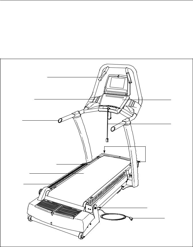
Before reading further, please familiarize yourself with the parts that are labeled in the drawing below.
Handgrip Pulse Sensor |
|
Accessory Tray |
Console |
Handrail |
Key/Clip |
|
|
|
Roller Adjustment Bolts |
Cushioned Walking Platform |
|
Walking Belt |
|
Foot Rail |
|
|
On/Off Circuit Breaker |
|
Power Cord |
|
6 |
ASSEMBLY
Assembly requires two persons. Set the incline trainer in a cleared area and remove all packing materials. Do not dispose of the packing materials until assembly is completed. Assembly can be completed using a 3/8" hex key, a 7/32" hex key, and a Phillips screwdriver.
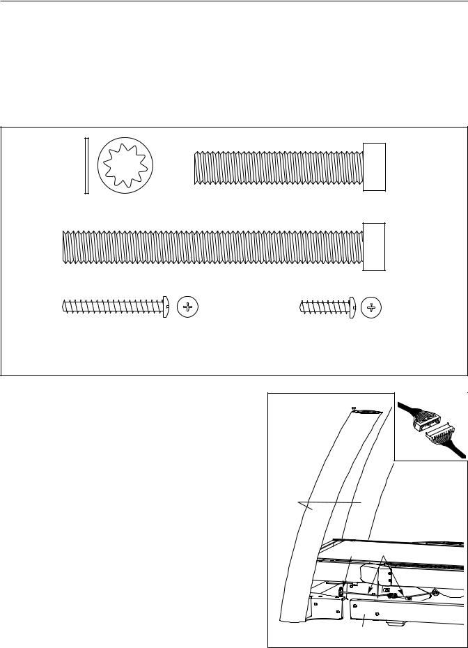
For help identifying assembly hardware, see the drawings below. Note: If a part is not found in the hardware kit, check to see if the part has been preattached. To avoid damaging plastic parts, do not use power tools for assembly.
1/2" Star |
Side Base Bolt (95)–4 |
Washer (124)–4 |
|
|
Top Base Bolt (96)–4 |
Console Plate Screw |
Display Mounting Screw |
(94)–4* |
(114)–5* |
*These Screws are included only with the Workout TV console INCLINE TRAINER.
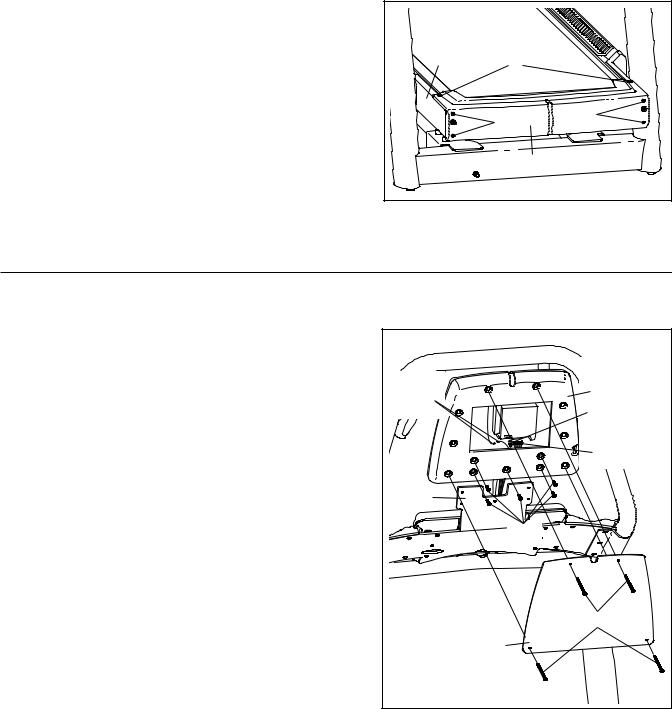
1. Place the Uprights (93) near the front of the Base Frame |
1 |
|
|
|
|
(56) as shown. |
|
|
|
|
|
|
|
|
|
|
|
Connect the indicated wires on the right side of the in- |
|
|
|
|
|
cline trainer. See the inset drawing. The connectors |
|
|
|
|
|
should slide together easily and snap into place. |
If |
|
|
|
|
they do not, turn one connector and try again. IF THE |
|
|
|
|
|
CONNECTORS ARE NOT INSERTED PROPERLY, |
|
|
|
|
|
THE CONSOLE MAY BE DAMAGED WHEN THE |
|
|
|
|
|
POWER IS TURNED ON. |
|
93 |
|
|
|
Insert the excess wire into the indicated hole in the |
|
|
|
|
RIGHT |
Upright (93). |
|
|
|
|
|
|
|
|
Hole |
Wires |
|
|
|
LEFT |
56 |
|
|
7
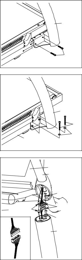
2. Slide the Uprights (93) onto the Base Frame (56), and |
2 |
|
|
align the holes in the Uprights with the holes in the Base |
|
|
|
|
|
|
|
Frame. Be careful to avoid pinching the wires. Finger |
|
|
|
tighten two Side Base Bolts (95) through the bracket |
|
|
|
near the right Upright and into the Base Frame; do not |
|
|
93 |
tighten the Side Base Bolts yet. |
|
|
|
Repeat this step on the left side of the incline |
|
|
|
trainer; there are no wires on the left side. |
|
|
|
|
56 |
|
95 |
|
|
|
|
3. Finger tighten two Top Base Bolts (96) with two 1/2" Star |
3 |
|
|
Washers (124) through the top of the bracket near the |
|
|
|
|
|
|
|
right Upright (93) and into the Base Frame (56); do not |
|
|
|
tighten the Top Base Bolts yet. |
|
|
|
Repeat this step on the left side of the incline |
|
|
|
trainer. |
|
|
|
Then, tighten the Top Base Bolts (96) and the Side Base |
|
|
93 |
Bolts (95) on both sides. |
|
|
|
|
|
|
96 |
|
56 |
95 |
124 |
|
|
|
|
4. Locate the Bolt (B) on the top of each Upright (93). With |
4 |
|
Console |
the help of a second person, set the console assembly |
|
||
|
|
||
onto the top of the Uprights. Make sure that the Bolts |
|
|
Assembly |
are inserted into the indicated holes in the bottom of |
|
|
103 |
the console assembly (only one side is shown). Be |
|
|
|
careful not to pinch any wires. Pull up on the Handrail |
|
|
|
(103) and carefully tip the console assembly forward so |
|
|
|
that you can see the indicated wires. Make sure the |
|
|
Hole |
console assembly is held securely by the Bolts. |
|
|
|
|
|
|
|
Connect the wire in the right Upright (93) and the wire in |
TV Cables |
|
Wires |
the console assembly. See the inset drawing. The |
|
||
|
|
||
connectors should slide together easily and snap |
|
|
B |
into place. If they do not, turn one connector and try |
|
|
|
again. IF THE CONNECTORS ARE NOT INSERTED |
|
|
|
PROPERLY, THE CONSOLE MAY BE DAMAGED |
|
|
93 |
WHEN THE POWER IS TURNED ON. If there is a TV |
|
|
|
cable, connect the TV cable in the console assembly to |
|
|
|
the TV cable in the right Upright. Then, insert the wires |
|
|
|
down into the right Upright. |
|
|
|
8
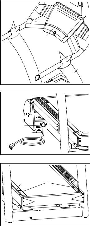
5.With the help of a second person, pivot the console assembly to the position shown. Be careful to avoid pinching your hands or the wires.
Align the Handrail Bolts (102) with the holes in the tops of the Uprights (93). Start all four Handrail Bolts, and then firmly tighten them.
6.After the incline trainer is placed in the location where it will be used (see HOW TO MOVE THE INCLINE TRAINER on page 11), make sure that both Rear Leveling Feet (38) and the Base Pads (not shown) rest firmly on the floor. If the incline trainer rocks even slightly, turn the right Rear Leveling Foot clockwise or counterclockwise until the rocking motion is eliminated.
Note: The Power Cord Bracket (64) must be attached at all times.
5 |
|
102 |
|
Console |
|
Assembly |
102 |
|
|
|
93 |
6 |
|
64 38 |
|
7.Remove the two Cover Screws (2) and the four Front Cover Screws (16) from the Frame (22).
7 |
|
|
22 |
|
2 |
|
16 |
16 |
|
|
9
8.Attach the Front Cover (17) to the Frame (22) with the two Cover Screws (2) and the four Front Cover Screws (16).
8 |
|
|
22 |
2 |
|
|
|
|
|
16 |
16 |
|
|
|
|
|
17 |
9.Make sure that all parts are properly tightened before you use the incline trainer. To protect the floor or carpet, place a mat beneath the incline trainer.
If you purchase the Workout TV console, follow the steps below to assemble the console.
1. Unplug the power cord. Remove the four Console |
|
|
|
Plate Screws (94) and the Basic Console Plate (not |
|
|
|
shown). Remove the five #8 x 3/4" Screws (85) from the |
|
|
|
back of the Basic Console (not shown), and remove the |
Ground |
|
A |
Basic Console from the incline trainer. Disconnect all |
|
||
Wires |
|
TV Cable |
|
wires connecting the Basic Console to the incline trainer. |
|
|
|
2. Insert the wire harness, the TV cable, and the ground |
|
|
Wire |
|
|
Harness |
|
wire into the bottom of the TV Console Assembly (A) as |
|
|
|
you slide the TV Console Assembly onto the bracket on |
103 |
|
|
the Handrail (103). Connect the wire harness, the TV |
|
|
|
cable, and the ground wire to the back of the TV |
|
|
85 |
Console Assembly. Make sure to connect the connec- |
|
|
|
tors properly. |
|
|
|
Align the indicated five holes in the back of the TV |
|
|
|
Console Assembly (A) with the five holes in the bracket |
|
|
|
on the Handrail (103). Attach the TV Console Assembly |
|
|
94 |
with five #8 x 3/4" Screws (85). Be careful not to pinch |
|
|
|
any wires. |
|
118 |
|
|
|
|
|
Attach the TV Console Plate (118) to the TV Console |
|
|
|
Assembly (A) with four Console Plate Screws (94). |
|
|
|
10
HOW TO MOVE THE INCLINE TRAINER
Before moving the incline trainer, unplug the power cord. Note: It may be necessary to disconnect a CATV cable and a network wire from the incline trainer, depending on how far the incline trainer will be moved.
Due to the size and weight of the incline trainer, moving it requires two or three persons. Hold the metal frame firmly in the location shown at the right. CAUTION: To decrease the possibility of damage to the incline trainer or of injury, do not lift the frame by the plastic front cover. Carefully roll the incline trainer on the wheels to the desired location and then lower it back to the level position. CAUTION: To reduce the risk of injury, use extreme caution while moving the incline trainer. Do not attempt to move the incline trainer over uneven surfaces.
Front Frame
Cover


 Wheels
11
HOW TO CONNECT THE INCLINE TRAINER
DANGER: Improper connection of equipment-grounding conductor can result
in an increased risk of electric shock. Check with a qualified electrician or serviceman if you are in doubt as to whether the product is properly grounded. Do not modify the plug provided with the product—if it will not fit the outlet, have a proper outlet installed by a qualified electrician. Do not use an adapter to connect the plug to an improper receptacle.
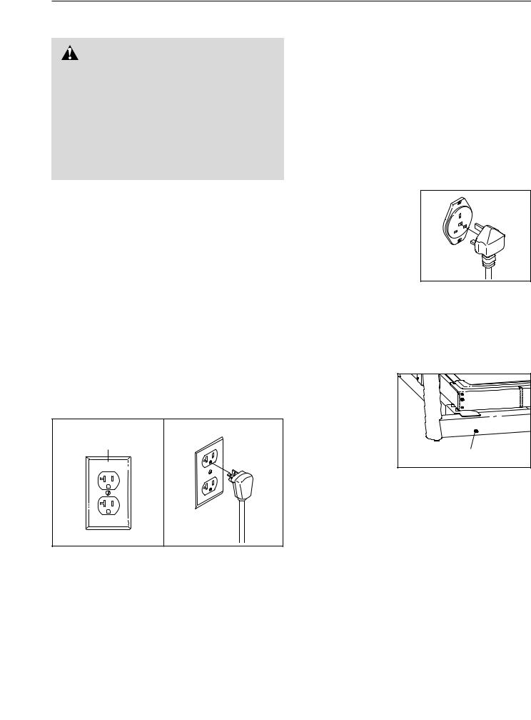
HOW TO CONNECT THE POWER CORD IN THE UNITED STATES
This product must be grounded. If it should malfunction or break down, grounding provides a path of least resistance for electric current to reduce the risk of electric shock.
This product is for use on a dedicated, 20-amp, 120-volt circuit. No other appliance should be on the same circuit. This product is equipped with a cord having an equipment-grounding conductor and a grounding plug.
Plug the grounding plug into a standard NEMA 5-20 receptacle. Do not modify the plug or the receptacle. Do not use an adapter, a surge protector, or an extension cord. The receptacle must be grounded.
NEMA 5-20
Receptacle
12
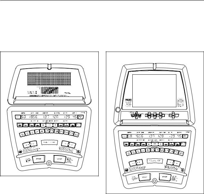
HOW TO UPGRADE THE CONSOLE
Your incline trainer has been pre-configured to operate with the Basic console or the Workout TV console (see the drawings below). To learn about the features of the Basic console, see page 14. To learn about the features of the Workout TV console, see the userʼs manual included with the Workout TV console.
To upgrade your console and expand the capabilities of the incline trainer whenever you choose, please see the back cover of this manual.
Basic Console |
Workout TV Console |
13
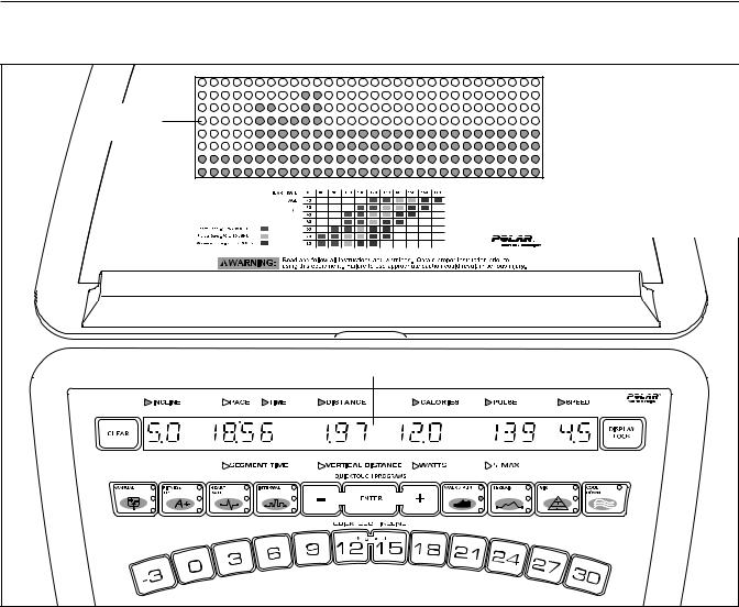
HOW TO USE THE BASIC CONSOLE
|
Note: If there is a |
Matrix |
sheet of clear plastic |
on the face of the |
|
|
console, remove it. |
Main Display
FEATURES OF THE CONSOLE
The Basic console offers an impressive array of features designed to help you get the greatest benefits from your exercise.
When the QUICK START mode is selected, the speed and incline of the incline trainer can be changed with the touch of a button. As you exercise, the console will provide continuous exercise feedback. You can even measure your heart rate using the built-in pulse sensor.
In addition, the console offers a wide selection of workout programs. Each program automatically controls the speed and/or incline of the incline trainer to give you an effective workout.
The console also offers three HEART RATE programs that adjust the speed and incline of the incline trainer
to keep your heart rate near target levels during your workouts, and three unique FITNESS TEST programs that measure your relative fitness level. Note: The HEART RATE programs and the FITNESS TEST programs require the use of a Polar®-compatible chest pulse sensor (not included).
Before using the incline trainer, please read OVERVIEW OF THE CONSOLE beginning on page 15. To use the QUICK START mode, see page 17. To use a MANUAL program, see page 18. To use a FITNESS TEST program, see page 20. To use a HEART RATE program, see page 22. To use an INTERVAL program, see page 24. To use a WALK/RUN program, see page 26. To use a TERRAIN program, see page 27. To use a FITNESS or RANDOM program, see page 28. To use a CUSTOM program, see page 29. To use the maintenance mode, see page 30.
14
OVERVIEW OF THE CONSOLE |
The DISPLAY LOCK |
For your benefit, please read all of the instructions |
button—This button can be |
used during your workout to |
|
on pages 15 and 16 before you use the incline |
keep the main display from |
trainer. |
scanning from one number to |
THE BUTTONS |
the next every few seconds. |
Each time the DISPLAY LOCK button is pressed dur- |
|
The CLEAR button—This |
ing your workout, the word LOCKED or UNLOCKED |
will briefly appear in the main display. |
|
button is used to reset the |
THE MAIN DISPLAY |
console. When this button is |
|
pressed, the main display |
The main display will display a variety of text mes- |
will be reset and the words |
|
SELECT PROGRAM TO |
sages to guide you through your workouts. In addition, |
BEGIN will appear in the main display. Note: If one |
the main display will display the following information |
program is started and then a different program is se- |
while you exercise: |
lected, the main display will not be reset unless the |
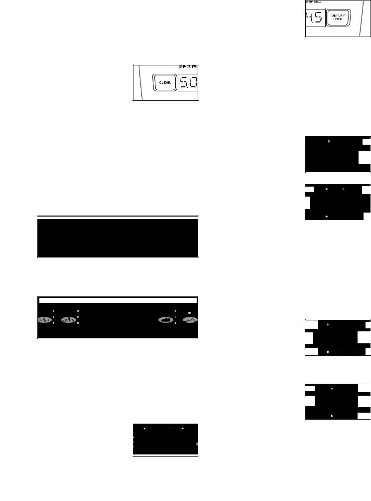
Incline—The left end of the |
CLEAR button is pressed before the second program |
|
is selected. |
main display will show the in- |
The QUICKTOUCH INCLINE buttons—These but- |
cline setting of the incline |
trainer. |
|
tons control the incline of the walking belt. To change |
|
the incline quickly, press the QUICKTOUCH INCLINE |
Pace/Time/Segment Time— |
buttons. Note: After the buttons are pressed, it may |
|
take a moment for the incline trainer to reach the se- |
When the QUICK START |
lected incline setting. |
mode, the MANUAL VERTI- |
|
CAL DISTANCE program, |
|
the MANUAL CALORIE pro- |
|
gram, or any of the |
|
WALK/RUN programs are selected, this section of the |
|
main display will show your pace, in minutes per mile |
|
or minutes per kilometer, the elapsed time, and the |
|
elapsed time in the current segment. The display will |
The QUICKTOUCH PROGRAMS buttons—These |
change from one number to the next every few sec- |
onds. When any other program is selected, the main |
|
buttons are used to select the various programs. |
display will show your pace, the time remaining in the |
|
program, and the time remaining in the current seg- |
|
ment of the program. The display will change from one |
|
number to the other every few seconds. |
|
Distance/Vertical |
|
Distance—This section of |
|
the main display will show |
The COOL DOWN button—This button is designed to |
the distance that you have |
walked or run, in miles or |
|
help you cool down after a workout. When you press |
kilometers, and the number |
the COOL DOWN button, the speed of the walking belt |
of vertical feet you have climbed. |
will automatically adjust to 3 mph (or 4.8 kph) and the |
Calories/Watts—This sec- |
incline will adjust to 0% for a three-minute cool-down |
|
walk. Note: If the walking belt is already moving at less |
tion of the main display will |
than 3 mph (or 4.8 kph), the speed of the walking belt |
show the approximate num- |
will not change. |
ber of calories you have |
The ENTER button and + |
burned and your power out- |
put in watts. The display will |
|
and – buttons—These but- |
change from one number to the other every few sec- |
tons are used to enter infor- |
onds. |
mation into the console. |
|
15
 Loading...