


www.freemotionfitness.com
Model No. SFCW81707.0 Serial No.
Write the serial number in the space above for reference.
Serial Number Decal (under frame)
QUESTIONS?
If you have questions, or if parts are damaged or missing, CONTACT
THE STORE WHERE YOU PURCHASED THIS PRODUCT.
If you are unable to contact the store, see HOW TO CONTACT CUSTOMER CARE on the back cover of this manual.
CAUTION
Read all precautions and instructions in this manual before using this equipment. Keep this manual for future reference.
USERʼS MANUAL
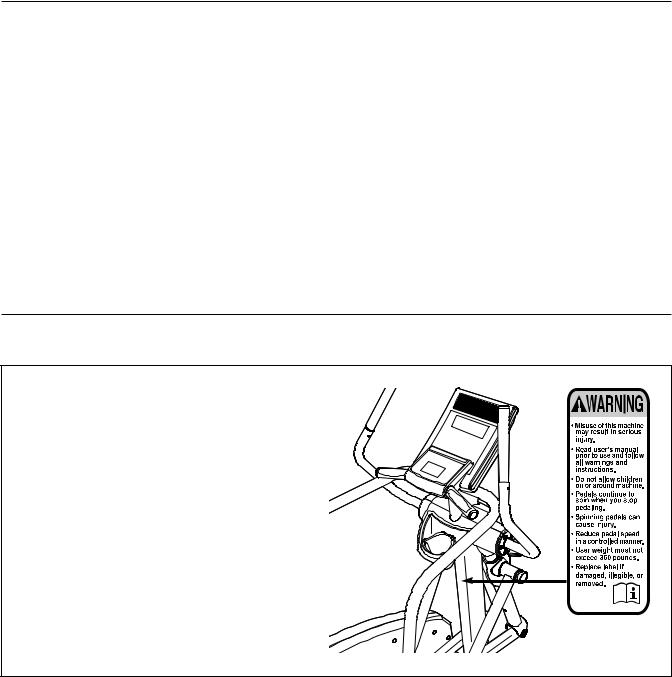
TABLE OF CONTENTS
WARNING DECAL PLACEMENT . . . . . . . . . . . . . . . . . . . . . . . . . . . . . . . . . . . . . . . . . . . . . . . . . . . . . . . . . . . . . .2 IMPORTANT PRECAUTIONS . . . . . . . . . . . . . . . . . . . . . . . . . . . . . . . . . . . . . . . . . . . . . . . . . . . . . . . . . . . . . . . .3 BEFORE YOU BEGIN . . . . . . . . . . . . . . . . . . . . . . . . . . . . . . . . . . . . . . . . . . . . . . . . . . . . . . . . . . . . . . . . . . . . . .4 ASSEMBLY . . . . . . . . . . . . . . . . . . . . . . . . . . . . . . . . . . . . . . . . . . . . . . . . . . . . . . . . . . . . . . . . . . . . . . . . . . . . . . .5 HOW TO USE THE ELLIPTICAL EXERCISER . . . . . . . . . . . . . . . . . . . . . . . . . . . . . . . . . . . . . . . . . . . . . . . . . .13 MAINTENANCE AND TROUBLESHOOTING . . . . . . . . . . . . . . . . . . . . . . . . . . . . . . . . . . . . . . . . . . . . . . . . . . .22 EXERCISE GUIDELINES . . . . . . . . . . . . . . . . . . . . . . . . . . . . . . . . . . . . . . . . . . . . . . . . . . . . . . . . . . . . . . . . . . .23 PART LIST . . . . . . . . . . . . . . . . . . . . . . . . . . . . . . . . . . . . . . . . . . . . . . . . . . . . . . . . . . . . . . . . . . . . . . . . . . . . . .24 EXPLODED DRAWING . . . . . . . . . . . . . . . . . . . . . . . . . . . . . . . . . . . . . . . . . . . . . . . . . . . . . . . . . . . . . . . . . . . .25 HOW TO CONTACT CUSTOMER CARE . . . . . . . . . . . . . . . . . . . . . . . . . . . . . . . . . . . . . . . . . . . . . . .Back Cover LIMITED WARRANTY . . . . . . . . . . . . . . . . . . . . . . . . . . . . . . . . . . . . . . . . . . . . . . . . . . . . . . . . . . . . . .Back Cover
WARNING DECAL PLACEMENT
This drawing shows the location(s) of the warning decal(s). If a decal is missing or illegible, see the back cover of this manual and request a free replacement decal. Apply the decal in the location shown. Note: The decal(s) may not be shown at actual size.
FREEMOTION is a registered trademark of ICON IP, Inc.
2

IMPORTANT PRECAUTIONS
WARNING: To reduce the risk of serious injury, read all important precautions and ructions in this manual and all warnings on your elliptical exerciser before using your elliptical
exerciser. FreeMotion Fitness assumes no responsibility for personal injury or property damage sustained by or through the use of this product.
1.Before beginning any exercise program, consult your physician. This is especially important for persons over the age of 35 or persons with pre-existing health problems.
2.It is the responsibility of the owner to ensure that all users of the elliptical exerciser are adequately informed of all precautions.
3.The elliptical exerciser is intended for home use only. Do not use the elliptical exerciser in a commercial, rental, or institutional setting.
4.Keep the elliptical exerciser indoors, away from moisture and dust. Place the elliptical exerciser on a level surface, with a mat beneath it to protect the floor or carpet. Make sure that there is enough clearance around the elliptical exerciser to mount, dismount, and use it.
5.Inspect and properly tighten all parts regularly. Replace any worn parts immediately.
6.Keep children under age 12 and pets away from the elliptical exerciser at all times.
7.The elliptical exerciser should not be used by persons weighing more than 350 lbs. (159 kg).
8.Wear appropriate exercise clothes when exercising; do not wear loose clothes that could become caught on the elliptical exerciser. Always wear athletic shoes for foot protection.
9.Hold the handles on the console or the handlebars when mounting, dismounting, or using the elliptical exerciser.
10.Keep your back straight while using the elliptical exerciser; do not arch your back.
11.The pulse sensor is not a medical device. Various factors, including the userʼs movement, may affect the accuracy of heart rate readings. The pulse sensor is intended only as an exercise aid in determining heart rate trends in general.
12.The elliptical exerciser does not have a freewheel; the pedals will continue to move until the flywheel stops. Reduce your pedaling speed in a controlled way.
13.Over exercising may result in serious injury or death. If you feel faint or if you experience pain while exercising, stop immediately and cool down.
14.Use the elliptical exerciser only as described in this manual.
3
BEFORE YOU BEGIN
Thank you for selecting the revolutionary FREEMOTION® E5.3 elliptical exerciser. The E5.3 elliptical exerciser provides an impressive selection of features designed to make your workouts at home more effective and enjoyable.
For your benefit, read this manual carefully before you use the elliptical exerciser. If you have questions after reading this manual, please see the back
cover of this manual. To help us assist you, note the product model number and serial number before contacting us. The model number and the location of the serial number decal are shown on the front cover of this manual.
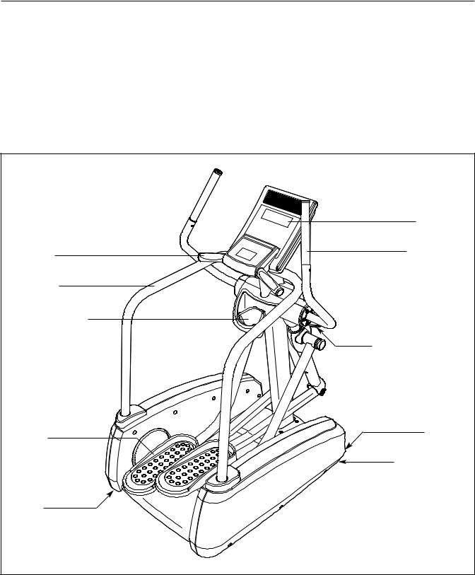
Before reading further, please familiarize yourself with the parts that are labeled in the drawing below.
|
Console |
Handle |
Handlebar |
Handrail |
|
Accessory Tray |
|
|
Adjustment Handle |
Pedal |
Wheel |
|
|
|
Leveling Foot |
Leveling |
|
Foot |
|
4
ASSEMBLY
Assembly requires two persons. Place all parts of the elliptical exerciser in a cleared area and remove the packing materials. Do not dispose of the packing materials until assembly is completed.
In addition to the included tool(s), assembly requires a Phillips screwdriver |
, an adjustable |
||
wrench |
, and a rubber mallet |
. |
|
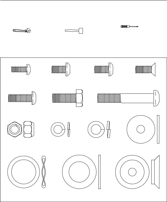
As you assemble the elliptical exerciser, use the drawings below to identify small parts. The number in parentheses below each drawing is the key number of the part, from the PART LIST near the end of this manual. The number following the parentheses is the quantity needed for assembly. Note: If a part is not in the hardware kit, check to see if it has been preassembled.
M6 x 16mm Patch |
M8 x 15mm Patch |
M8 x 15mm Bright |
M8 x 17mm Flat |
Screw (78)–12 |
Screw (61)–24 |
Patch Screw (92)–10 |
Patch Screw (91)–8 |
M8 x 25mm Bright |
M10 x 25mm Patch |
M10 x 60mm Button Bolt (70)–4 |
|
Patch Screw (87)–4 |
Hex Screw (95)–4 |
|
|
M10 Locknut |
M8 Split |
M10 Split |
Pivot Axle |
(63)–4 |
Washer (80)–18 |
Washer (79)–4 |
|
|
|
|
Washer (90)–2 |
34mm x 26mm Wave |
Thrust Washer |
Inner Pedal Bushing |
Washer (77)–2 |
(45)–4 |
(37)–4 |
5

1.To make assembly easier,read the information on page 5 before you begin.
Tip: Have a second person lift and hold each corner of the Frame (1) as you perform this step.
Remove the four screws and the four shipping brackets from the corners of the Frame (1). Discard the screws and the shipping brackets.
Then, tighten the four Leveling Feet (52) into the holes in the underside of the Frame (1).
2.Identify the Upright (2) and the Accessory Tray (54) and orient them as shown.
Press the Accessory Tray (54) into the Upright
(2).
1 |
|
|
|
|
52 |
|
1 |
|
|
|
Shipping Bracket |
|
|
Screw |
2 |
|
54 |
|
|
|
|
|
2 |
6
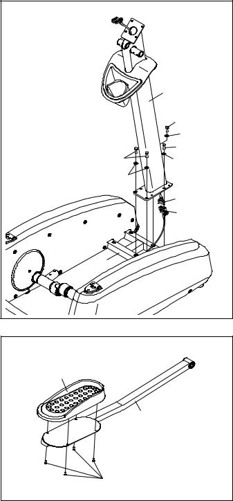
3.Orient the Upright (2) as shown. While a second person holds the Upright near the Frame (1), connect the Upper Wire Harness (81) to the Lower Wire Harness (82).
Tip: Avoiding pinching the Wire Harnesses (81, 82). Attach the Upright (2) to the Frame (1) with four M10 x 25mm Patch Hex Screws (95) and four M10 Split Washers (79). Do not tighten the Patch Hex Screws yet.
4.Identify the Right Pedal Arm (15), which is marked with a “Right” sticker.
Attach a Pedal (9) to the Right Pedal Arm (15) with four M6 x 16mm Patch Screws (78).
Attach the other Pedal to the Left Pedal Arm (not shown) in the same way.
3 |
|
|
|
|
2 |
Avoiding pinching |
|
95 |
|
79 |
|
the Wire Harnesses |
||
(81, 82) |
95 |
95 |
|
79 |
|
|
79 |
|
|
|
81 |
|
|
82 |
|
1 |
|
4 |
|
|
9 |
|
|
|
|
15 |
|
78 |
|
7
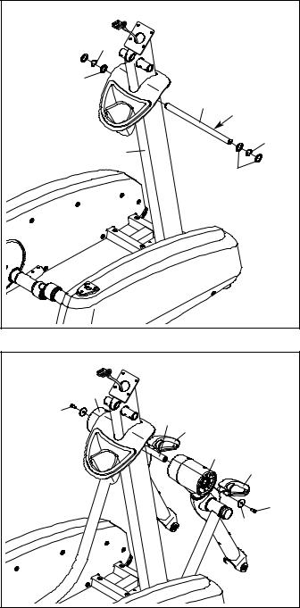
5.Apply a generous amount of the included grease to the Pivot Axle (35).
Insert the Pivot Axle (35) through the Upright (2), and center the Pivot Axle.
Next, slide a Thrust Washer (45), a 34mm x 26mm Wave Washer (77), and another Thrust Washer (45) onto each end of the Pivot Axle (35).
6.Identify the Left and Right Upper Handlebar Leg (12, 13) assemblies, which are marked with “Left” and “Right” stickers.
Orient the Left and Right Upper Handlebar Leg (12, 13) assemblies so that the Adjustment Handles (28) are in the indicated locations. Slide the Left and Right Upper Handlebar Legs (12, 13) onto the left and right sides of the Pivot Axle (35).
Attach the Left and Right Upper Handlebar Legs (12, 13) with two M8 x 15mm Patch Screws (61) and two Pivot Axle Washers (90).
5 |
|
|
|
|
|
|
|
77 |
|
|
|
|
45 |
|
35 |
|
|
|
|
|
Grease |
||
|
|
|
|
||
|
|
2 |
|
|
77 |
|
|
|
|
|
|
|
|
|
|
45 |
|
6 |
|
|
|
|
|
|
12 |
|
|
|
|
61 |
90 |
35 |
28 |
|
|
|
|
|
13 |
28 |
|
|
|
|
|
|
|
|
|
|
|
90 |
61 |
|
|
|
|
|
|
8
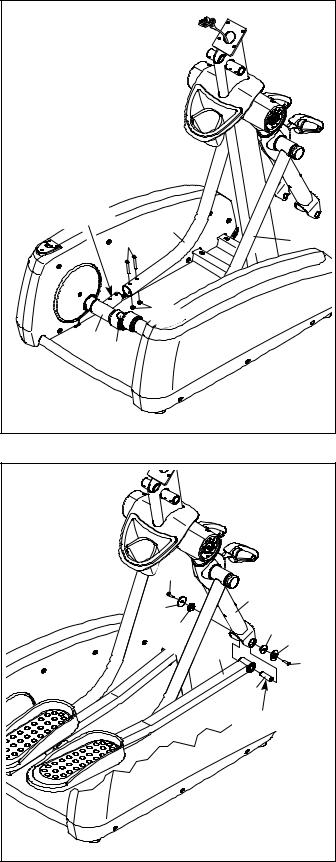
7. Identify the Left Pedal Leg (8), which is marked |
7 |
|
|
|
|
|
|
|
with a “Left” sticker. |
|
|
|
|
|
|
|
|
|
|
|
|
|
|
|
|
|
Apply a small amount of grease to the tube on |
|
|
|
|
|
|
|
|
the left Pedal Arm Bracket (43). |
|
|
|
|
|
|
|
|
Attach the Left Pedal Leg (8) to the left Pedal |
|
|
|
|
|
|
|
|
Arm Bracket (43) with two M10 x 60mm Button |
|
|
|
|
|
|
|
|
Bolts (70) and two M10 Locknuts (63). Tip: If |
|
|
|
|
|
|
|
|
necessary, rotate the Crank (40) to position |
|
|
|
|
|
|
|
|
the Left Pedal Leg near the left Pedal Arm |
|
|
|
|
|
|
|
|
Bracket. |
|
|
|
|
|
|
|
|
Attach the Right Pedal Leg (50) in the same |
Grease |
|
|
8 |
|
|
|
|
way. |
|
|
70 |
|
|
|
50 |
|
|
|
|
|
|
|
|
||
|
|
|
|
63 |
|
|
|
|
|
43 |
40 |
|
|
|
|
|
|
8. Identify the Right Pedal Arm (15) and the Right |
8 |
|
|
|
|
|
|
|
Upper Handlebar Leg (13) assembly, which are |
|
|
|
|
|
|
|
|
|
|
|
|
|
|
|
|
|
marked with “Right” stickers. |
|
|
|
|
|
|
|
|
Apply a small amount of grease to a Pedal Axle |
|
|
|
|
|
|
|
|
(56). Insert the Pedal Axle into the Right Pedal |
|
|
|
|
|
|
|
|
Arm (15). |
|
|
|
|
87 |
|
|
|
|
|
|
|
|
|
13 |
|
|
Position the Right Upper Handlebar Leg (13) as |
|
|
|
39 |
|
|
|
|
shown. Then, insert the Right Pedal Arm (15) |
|
|
|
37 |
|
37 |
|
|
into the Right Upper Handlebar Leg. |
|
|
|
|
|
39 |
||
Attach the Right Pedal Arm (15) with two M8 x |
|
|
|
|
|
15 |
|
|
|
|
|
|
|
|
87 |
||
|
|
|
|
|
|
|
||
25mm Bright Patch Screws (87), two Pedal Axle |
|
|
|
|
|
|
56 |
|
Covers (39), and two Inner Pedal Bushings (37). |
|
|
|
|
|
|
|
|
Do not overtighten the Bright Patch Screws; |
|
|
|
|
|
|
Grease |
|
the Right Pedal Arm must pivot easily. |
|
|
|
|
|
|
|
|
|
|
|
|
|
|
|
|
|
Attach the Left Pedal Arm to the Left Upper |
|
|
|
|
|
|
|
|
Handlebar Leg assembly (not shown) in the |
|
|
|
|
|
|
|
|
same way. |
|
|
|
|
|
|
|
|
|
9 |
|
|
|
|
|
|
|
 Loading...