


TS-550
Fuel Management System
Programming Guide
TS-550 evo
Franklin Fueling Systems • 3760 Marsh Rd. • Madison, WI 53718 USA
Tel: +1 608 838 8786 • 800 225 9787 • Fax: +1 608 838 6433 • www.franklinfueling.com

Notice
Franklin Fueling Systems (FFS) strives to produce the nest manual possible and to ensure that the information that it
contains is complete and accurate FFS periodically review the manuals. However, FFS reserves the rights to change this
document and specications at any time without notice. FFS makes no expressed or implied warranty with regard to the
contents of this manual. FFS assumes no liability for errors, omissions or for any damages, direct or consequential, that
may result from the use of this document or the equipment that it describes.
This manual is for use expressly with the T550evo at its approved specications. No part of this document may be
reproduced in any form without the prior written consent of FFS.
Open Source Notice
The TS-550 evo series consoles implement open source software released under the General Public License (GPL) as
well as other open source licenses. As a customer, you are entitled to receive a copy of the licensed source code used
within our product, if so desired. Please contact our sales staff for more information.
Trademarks
FFS®, Tank Sentinel®, TS-550 evo® System Sentinel®, SCALD®, Brite®, BriteBox®, BriteBus®, and BriteSensors® are
registered trademarks of Intelligent Controls. All brand and product names are trademarks or registered trademarks of
their respective companies.
Inspection of Materials
Visually inspect all components for defects or damage prior to installation. If any defect or damage is found, do not use the
product and contact FFS for further assistance.
Warranty Information
Please refer to the FFS Fuel Management Systems & Product Warranty Policy for all warranty information.
Contacting Franklin Fueling Systems (FFS)
Please feel free to contact us by mail at:
Franklin Fueling Systems
3760 Marsh Rd.
Madison, WI 53718 USA
Or contact us by phone, fax or e-mail:
Tel: +1 800 984 6266 E-mail: sales@franklinfueling.com
Fax: +1 608 838 6433 techserve@franklinfueling.com
Ofce and Sales Hours: 8am to 5pm CST - Monday through Friday
Technical Support Hours: 7am to 7pm CST - Monday through Friday
Please visit our website at www.franklinfueling.com
Copyright ©2011 by Franklin Fueling Systems. No part of this publication may be reproduced in any form without the prior written consent of FFS. All
2
rights reserved.

Contents
Notice..................................................................................................................................2
Important Safety Messages .............................................................................................. 5
Introduction ........................................................................................................................7
FMS Functions ..........................................................................................................................7
Denitions and Acronyms .........................................................................................................8
Related Documentation ............................................................................................................ 8
General ...............................................................................................................................9
User Interfaces (UI) ..................................................................................................................9
LCD Touch Screen Interface .......................................................................................................... 9
Web Browser Interface .................................................................................................................... 9
Access Control ................................................................................................................................ 9
Connecting a PC or Laptop Computer ...................................................................................... 10
Conguring IP Settings for Communication .................................................................................... 10
Obtain an IP Address Automatically ................................................................................................ 12
Use the Following IP Address ......................................................................................................... 12
Check Status of Connection ............................................................................................................ 12
Programming and Navigation ..........................................................................................13
Console Navigation ...................................................................................................................13
Navigation Buttons .......................................................................................................................... 13
Quick Jump Menu (QJM) ..................................................................................................... 13
Text Entry Screen ............................................................................................................................ 14
Number Entry Screen ...................................................................................................................... 14
Initial Console Conguration ..................................................................................................... 15
Touch Screen Calibration .........................................................................................................................15
Console Build Characteristics ................................................................................................... 15
Setup Menu ..............................................................................................................................15
Conguration Options...................................................................................................................... 15
Modifying Passwords ...................................................................................................................... 15
Date / Time Set ................................................................................................................................. 16
Time Zone ....................................................................................................................................... 16
Toggle Sleep Mode.......................................................................................................................... 16
Network Parameters ........................................................................................................................ 16
FAST - Franklin Auto Setup Tool ............................................................................................... 17
Programming System Parameters ............................................................................................ 17
Preferences .............................................................................................................................17
Language ........................................................................................................................................ 17
Date / Time ....................................................................................................................................... 17
Numbers .......................................................................................................................................... 18
Units ................................................................................................................................................ 18
System ID .................................................................................................................................19
System Conguration ...................................................................................................................... 19
Communications ....................................................................................................................... 20
Programming Modules .................................................................................................................... 21
IO Modules ............................................................................................................................................... 21
AC Input Modules.....................................................................................................................................21
Probe Modules .........................................................................................................................................21
2-Wire Sensor Modules............................................................................................................................22
3-Wire Sensor Modules............................................................................................................................22
4-20 mA and 4-20 mA EXP Input Modules .............................................................................................. 22
Power Supply Module ..............................................................................................................................23
Relay Modules .........................................................................................................................................25
Dispenser Interface ..................................................................................................................................26
Programming FMS Parameters ...............................................................................................................27
Fuel Management System .......................................................................................................................27
Manifold Tank System ..............................................................................................................................28
3

Web Browser Interface ...................................................................................................... 31
Navigating Applications Remotely ............................................................................................ 31
Accessing the Web Browser Interface ............................................................................................ 31
Making Changes to System Parameters .................................................................................. 31
Password Prompting .................................................................................................................31
Setup ........................................................................................................................................31
Backup Setup Files ................................................................................................................... 32
DIM Programming ..................................................................................................................... 34
Rules ............................................................................................................................................... 37
Dual DIM Installation ....................................................................................................................... 38
Hardware Conguration .................................................................................................................. 38
Device Address ............................................................................................................................... 38
Communication Settings ................................................................................................................. 38
TS-TPI Overview and Functionality ........................................................................................ 39
List of Alarms and Troubleshooting ................................................................................ 41
Appendix A - Standard Tanks Table ................................................................................. 50
Appendix B - Standard Products Table ........................................................................... 52
Appendix C - Typical Tank Leak Test Times ...................................................................52
4
Important Safety Messages
FFS equipment is designed to be installed in association with volatile hydrocarbon liquids such as gasoline and diesel
fuel. Installing or working on this equipment means working in an environment in which these highly ammable liquids
may be present. Working in such a hazardous environment presents a risk of severe injury or death if these instructions
and standard industry practices are not followed. Read and follow all instructions thoroughly before installing or working
on this, or any other related, equipment.
As you read this guide, please be aware of the following symbols and their meanings:
Warning
Caution
Danger
Warning
This symbol identies a warning. A warning sign will appear in the text of this document when a potentially
hazardous situation may arise if the instructions that follow are not adhered to closely. A potentially hazardous
situation may involve the possibility of severe bodily harm or even death.
This is a caution symbol. A caution sign will appear in the text of this document when a potentially hazardous
environmental situation may arise if the instructions that follow are not adhered to closely. A potentially
hazardous environmental situation may involve the leakage of fuel from equipment that could severely harm
the environment.
This symbol identies an electrical danger. An electrical danger sign will appear in the text of this document
when a potentially hazardous situation involving large amounts of electricity may arise if the instructions that
follow are not adhered to closely. A potentially hazardous situation may involve the possibility of electrocution,
severe bodily harm, or even death.
Alarms and warnings are designed to alert you with specic details when a problem occurs so you can
take appropriate corrective action. System hardware failure warnings, tank related alarms, leak detection
sensor alarms, and line leak alarms can be custom programmed to do many things. The events that require
programming are denoted by a (p) below:
- cause the red Alarm light or yellow Warning light to ash (standard)
- activate / sound the console annunciator alarm horn (p)
- activate internal output relays for external alarm devices (p)
- print alarm reports automatically, either locally (internal printer), or remotely (USB - HP compatible printer) (p)
- send alarm and test reports to a specied e-mail address (p)
- send reports to remote location(s), via internal data/fax modem (p)
Follow all applicable codes governing the installation and servicing of this product and the
entire system. Always lock out and tag electrical circuit breakers while installing or servicing
this equipment and any related equipment. A potentially lethal electrical shock hazard and the
possibility of an explosion or re from a spark can result if the electrical circuit breakers are
accidentally turned on during installation or servicing. Please refer to the Installation and Owner’s
Manual for this equipment, and the appropriate documentation for any other related equipment, for
complete installation and safety information.
Warning
Warning
Warning
Warning
Warning
Follow all federal, state and local laws governing the installation of this product and its associated
systems. When no other regulations apply, follow NFPA codes 30, 30A and 70 from the National Fire
Protection Association. Failure to follow these codes could result in severe injury, death, serious
property damage and/or environmental contamination.
Always secure the work area from moving vehicles. The equipment in this manual is usually
mounted underground, so reduced visibility puts service personnel working on this equipment in
danger from moving vehicles entering the work area. To help eliminate these unsafe conditions,
secure the area by using a service truck to block access to the work environment, or by using any
other reasonable means available to ensure the safety of service personnel.
When the Fuel Management System is used to monitor tanks containing gasoline or other
ammable substances, you may create an explosion hazard if you do not follow the requirements in
this manual carefully.
All wiring must enter the console’s enclosure through the designated knockouts. An explosion
hazard may result if other openings are used.
You must run wiring from probes or sensors to the Fuel Management System console in conduits
which are separate from all other wiring. Failure to do so will create an explosion hazard.
5

Warning
Certied Programmer/Service Person: Only an FFS certied programmer or service person is allowed to access both
the user interface keypad and areas internal to the Fuel Management System console.
Station Owner/Operator: The station owner or operator of the Fuel Management System console is only allowed to
access the user interface keypad. Access to areas internal to the console is strictly prohibited.
Substituting components could impair intrinsic safety. TS-550evo consoles are intrinsically safe
for sensors installed in – Class I, Division 1, Group D – hazardous locations. Substitution of
components could make the energy limiting circuitry in the system ineffective and could cause
an explosion hazard. Repairs to a TS-550 evo console or attached components should only be
performed by a qualied, factory-trained technician.
Approvals
All Fuel Management System models are UL and cUL listed 6L79 as Liquid Level Gauge / Leak Detection
Systems. Third party approved leak detection — Pd (probability of detection) = 99.2 % for 0.1 or 0.2 gph leak tests
(0.1 = annual precision test, 0.2 is the monthly regulatory compliance test).
*The static tank test does not support Manifolded tanks.
**SCALD is 3rd party approved for up to three Manifolded tanks.
6

Introduction
The purpose of this manual is to guide installers, operators and technicians through programming and troubleshooting
the TS-550 evo console, so that it’s congured based on a site’s specic needs. The Fuel Management Systems (FMS)
application within the TS-550 evo console tie together the monitoring and alarm capabilities of the automatic tank gauge
with advanced technologies to supply tank and level data more accurately and efciently. This manual is also designed
to introduce technicians to the LCD Graphical User Interface, which is used as an input device to program system
conguration and maintain all applications from the front panel of the console as well as through a web interface. Overall
safety issues, troubleshooting information, warranty, service and return policies, as dened in this manual, must be
followed.
FMS Functions
The main function of the Fuel Management System is to represent levels for inventory and tank leak testing by monitoring
probe inputs and performing calculations based on those inputs. Line leak transducers provide line pressure data
to perform line leak detection. Results from these calculations may be used for system monitoring and/or regulatory
compliance. The console, in conjunction with external fuel system equipment, may provide positive system shutdown,
based on programmed rules.
Sites that use Fuel Management Systems have the ability to monitor and perform:
• Tank Inventory Information
• Tank Leak Detection
• Sensor Conguration and Monitoring
• Line Leak Detection
• Sump Leak Detection
• Compliance Line and Leak Testing
• Secondary Containment Monitoring
FMS also allows sites to generate and print the following reports:
• Inventory Reports
• Delivery Reports
• Tank Test Results
• SCALD Testing Reports
• Regulatory Reports
• Sensor Reports
• Line Leak Reports
• Reconciliation Reports
7

Denitions and Acronyms
Module – A module is a plug-in card within the T5 series console that is used to perform various console functions. The
modules are used for eld wiring of the input and / or output of electrical signals between different equipment.
RS-232 – An IEEE standard for serial communication using a 9-pin connector.
RS-485 – An IEEE standard for serial communication using Shielded Twisted Pair or Unshielded Twisted Pair wiring.
RJ-45 – An IEEE standard connector for use in communications with Shielded Twisted Pair wiring. Usually data.
RJ-11 – An IEEE standard connector for use in communications using Shielded Twisted Pair wiring. Usually voice and fax.
2SM – 2-Wire Sensor Module (Intrinsically Safe)
ACIM – AC Input Module
AIM – 4-20mA Analog Input Module (Intrinsically Safe)
AST – Aboveground Storage Tank
ATG – Automatic Tank Gauge
CARB – California Air Resources Board
CM – Controller Module
DCE – Data Communication Equipment
DIM – Dispenser Interface Module
DTE – Data Terminal Equipment
DTU – Data Transfer Unit
DW/DWT – Double Wall/Double Wall Tank
EVR – Enhanced Vapor Recovery
FAST – Franklin Auto Setup Tool
FMS – Fuel Management Systems
IS – Intrinsically Safe
ISD – In-Station Diagnostic
LCD – Liquid Crystal Display
LIM – LonWork Interface Module
LLD – Line Leak Detection
NC – Normally Closed
NO – Normally Open
OTB – One Touch Button
PC – Personal Computer
PM – Probe Module (Intrinsically Safe)
PSM – Power Supply Module
QJM – Quick-Jump Menu
RTD – Resistance Temperature Detectors
RM – Relay Module
SCM – Secondary Containment Monitoring
SLLD - Statistical Line Leak Detection
STP – Submersible Turbine Pump
TPI – Turbine Pump Interface
TS-EMS – Environmental Monitoring System
TS-EXPC – Expansion Console
URL – Uniform Resource Locator for the internet
USB – Universal Serial Bus
UST – Underground Storage Tank
VFM – Vapor Flow Meter
V/L – Vapor to Liquid ratio
VRM – Vapor Recovery Monitoring
XML – eXtensible Markup Language
Related Documentation
The system installation and operation instructions, troubleshooting guide and console maintenance manual are provided
for your use in separate documents. Detailed installation and testing instructions for each type of leak detection sensor
are present in the relevant manual, and, likewise, the installation, testing, and programming of various upgrade kits and
optional accessories are also contained in separate manuals, addenda or in one of this document’s appendices.
TS-550 evo Series Fuel Management Systems Installation Guide (000-2170)
TS-550 evo Series Fuel Management Systems Operators Guide (000-2171)
8

General
After the Fuel Management System has been installed, typically your interaction with the system will be from the LCD
display, on-board printer; or using a Web Browser to program and monitor the console. Remote operation can be
performed from a PC, either attached directly or through a network connection to the console. All of the features of
the console are available through these input / output devices. Also, the console may be set up to generate and send
automated reports to e-mail accounts or print reports at a programmed time.
Occasionally you may need console information, such as model and serial numbers. The model number is located on the
face of the console. The serial number is located on a small plaque placed on the bottom of the left panel. This label also
shows the model number, voltage, manufacturer’s address, a warning symbol and the unit’s voltage specications.
User Interfaces (UI)
LCD Touch Screen Interface
A color LCD touch screen is included with the TS-550 evo console. This bright display allows easy viewing in any lighting
condition. Console functions are easily accessed through the LCD screen.
Web Browser Interface
The TS-550 evo console includes an Ethernet port and programming options to allow the system to be installed on a
network. The advantages to using an Ethernet connection are: faster connection speeds, quicker data transfer rates,
less data errors or quicker recovery of data when errors occur, and it does not require extra software or drivers to be
loaded. This means that console parameters can be modied and that status / alarm reports can be printed from virtually
anywhere.
Access Control
There are three access levels programmed into the console’s operating system: Guest, User, and Administrator. Each
level will allow an operator to access different features or change specic settings on the console. This security feature
prevents unauthorized tampering of console congurations. The system will prompt the user for a password when
required.
Default passwords are as follows:
Guest: (none required)
User: user
Administrator: admin
9
Connecting a PC or Laptop Computer
To access the console using the Web Browser interface,
connect a PC to the console through either the Ethernet
port or the COMM 1 serial port. If the console is connected
to a local network, you can perform this setup from any
PC on that network by using a web browser, such as
Microsoft’s Internet Explorer or Mozilla’s FireFox, or Safari
for a Mac.
Note: The PC or laptop will recognize this serial
connection as a network connection and will
not allow the use of a Local Area Connection
simultaneously. While it is not necessary to
disconnect the Local Area Connection to connect
using the Serial port, it will be necessary to
disconnect the Serial Connection through the
computers operating system in order to use the
Local Area Connection again.
The following instructions are written specically for
Microsoft’s Windows 7 operating system. For assistance
with other operating systems, please contact Franklin
Fueling Systems Technical Services.
Connecting a PC to the TS-550 evo Ethernet Port
1. Using an Ethernet Crossover, 10 Base-T cable,
plug the RJ-45 connector on one end of the cable
into the Ethernet port of the console.
2. Plug the RJ-45 connector on the opposite end
of the cable to the Network Interface Card of the
computer.
3. Power up and log onto your PC.
Note:
Note: Some modern laptops have automatically switching
You may need to re-congure your TCP / IP settings to
allow the computer to communicate with the console.
Network Interface Cards and as such, will require the
use of a standard cat 6 cable instead of a crossover.
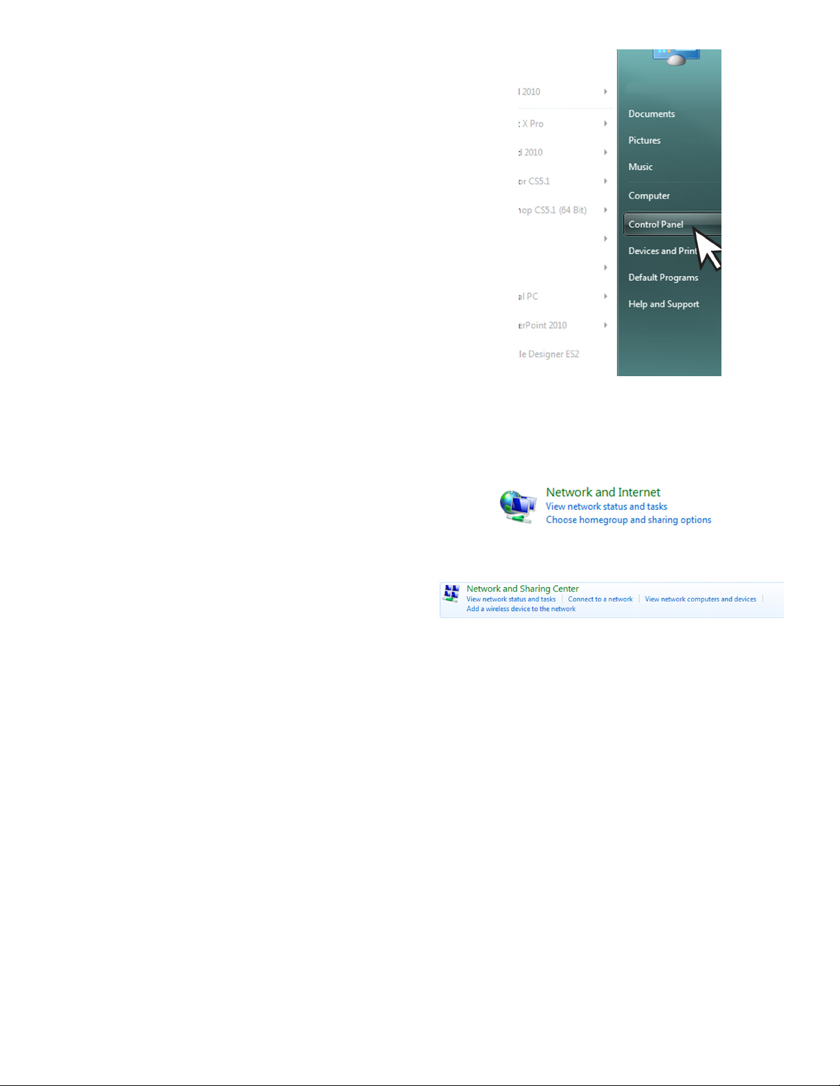
3. There are (2) two views settings possible when
using Windows 7:
• In Category View, click on Network and Internet,
then click View Network Status and tasks under
Network and Sharing Center.
↓
Conguring IP Settings for Communication
Before attempting to modify any computer settings, contact
the Information Technologies department of your business,
if available. Some computer accounts may have restricted
permissions to overcome before any changes are allowed
to be made to TCP / IP settings.
At the PC:
1. Power up the PC and log into your Windows
operating system.
2. Click on Start, then select Control Panel.
10
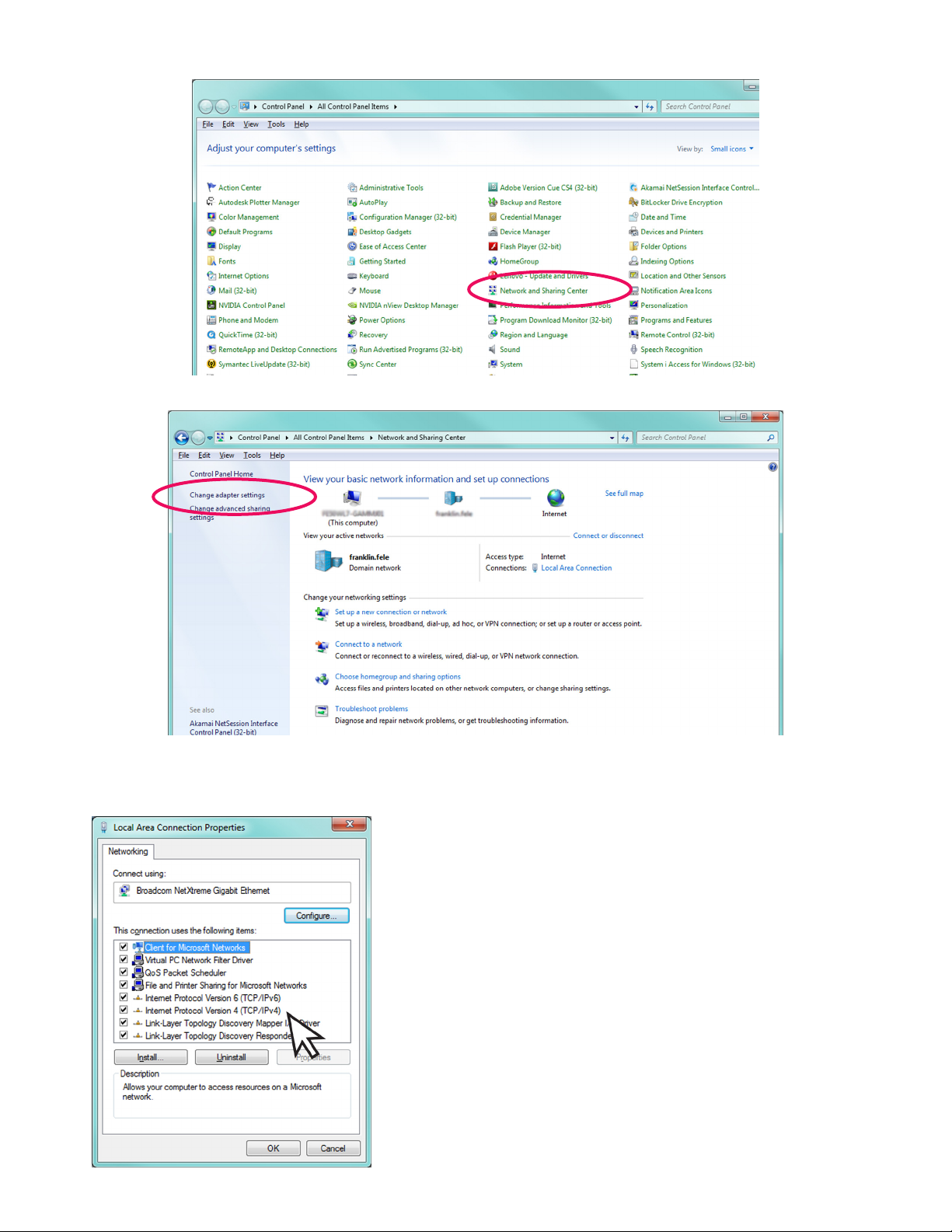
• In Icon View, click on Network and Sharing Center.
4. Click on the Change adapter settings in the left hand column.
5. Right-click on Local Area Connection and select Properties.
6. In the Local Area Connection Properties dialog box, under “This connection uses the following items,” select
Internet Protocol Version 4(TCP / IPv4) and click Properties.
There are various ways to congure a computer to
communicate with a TS-550 evo console. These factors
depend upon the user’s computer knowledge and how the
computer is currently congured.
To determine which method is best for your site, read the
instructions in the following section carefully. Make detailed
notes on the current conguration of the TCP / IP settings on
the PC you are using. Read both the “Obtain an IP address
automatically” and the “Use the following IP address” methods
before making a choice between the two.
11
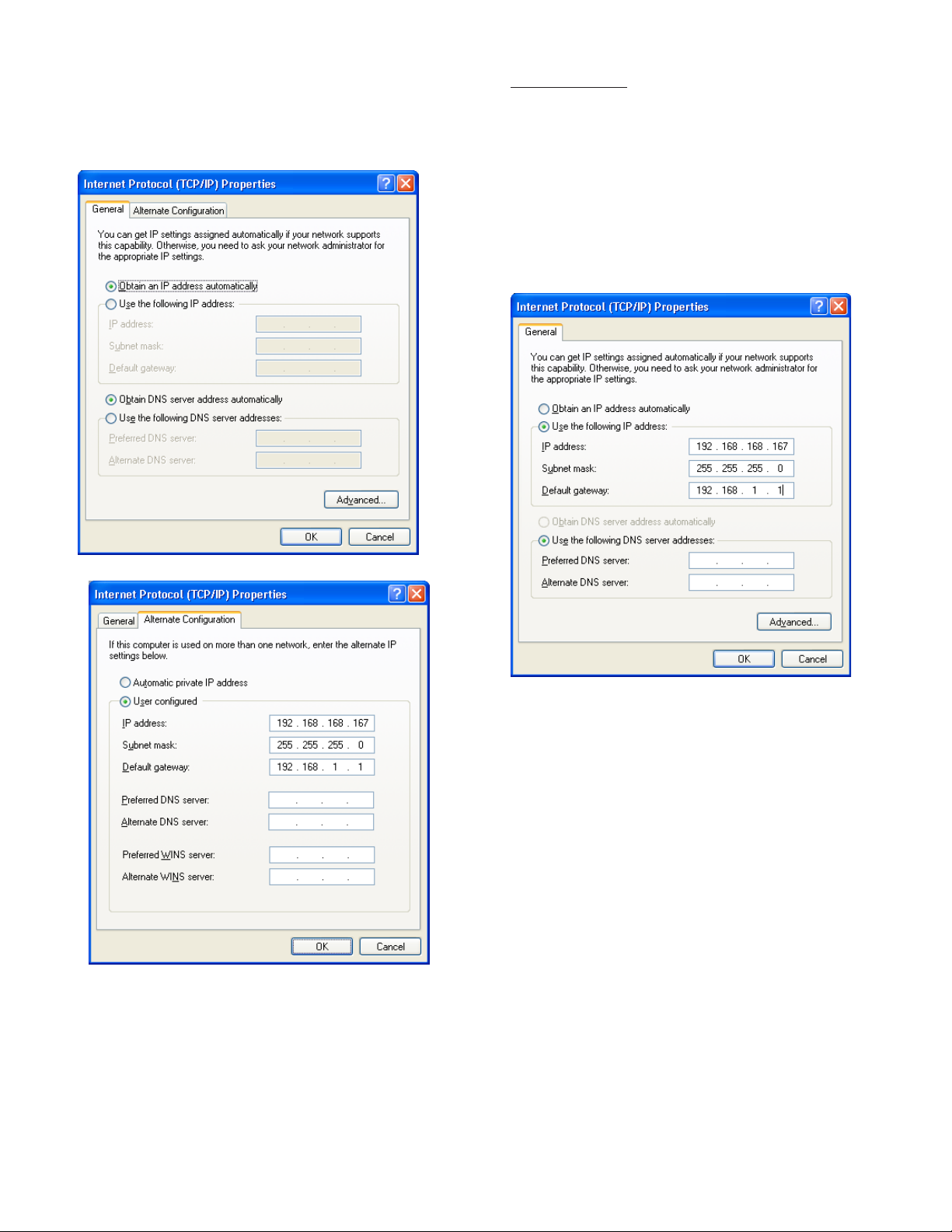
Obtain an IP Address Automatically
Computers commonly use this setting to obtain an IP
address automatically.
1. If Obtain an IP address automatically is
selected, it may be best to click the Alternate
Conguration tab.
Note: The consoles default IP address is
192.168.168.168. If the PC is normally congured
to acquire an IP address automatically, Alternate
Conguration may be used, as mentioned above, to
allow a connection to be enabled without the necessity
of reconguring the computer each time it will be used
to connect to this console.
Use the Following IP Address
1.
If Use the following IP address is selected and
the entry boxes contain any information, record this
information for use when console programming is
complete.
2. Select User Congured.
3. Enter an IP address. For simplicity, make the last
segment of the IP one number different than the IP
address of the console. Upon initial setup ONLY,
the numbers used in the gure may be used to
congure the TCP / IP settings of your PC. After
initial startup the programmed parameters should
be veried through the touchscreen
4. Leave all other information blank and click OK.
5. Close the Local Area network for changes to take
place.
2. Enter an IP address. For simplicity, make the last
segment of the IP one number different than the IP
address of the console. Upon initial setup ONLY,
the numbers used in the gure may be used to
congure the TCP / IP settings of your PC.
3. Leave the DNS information blank.
Note: The consoles default IP address is
192.168.168.168. If the PC is normally congured
to Use the following IP address, make sure that
all displayed information is recorded and kept prior
to making any changes. It may be necessary to use
this information to re-congure the console once
programming is complete.
Check Status of Connection
1. Check the status of your connection by going to
the Network Connections window.
2. If the connection status is disabled, enable it by
right-clicking on the Local Area Connection and
selecting Enable.
3. Verify link light is lit under Ethernet on Controller
module is lit and RX light is ashing.If technical
difculties arise, please contact Franklin Fueling
Systems Technical Support before proceeding.
More information on the Web Browser Interface is located
on page 31 of this manual.
12
Programming and Navigation
Console Navigation
The operating system is designed for easy navigation. Applications allow the user to modify programming options by
responding to on-screen commands. The following instructions show various operating system functions, so that issues
can be corrected efciently without interrupting dispensing or sales.
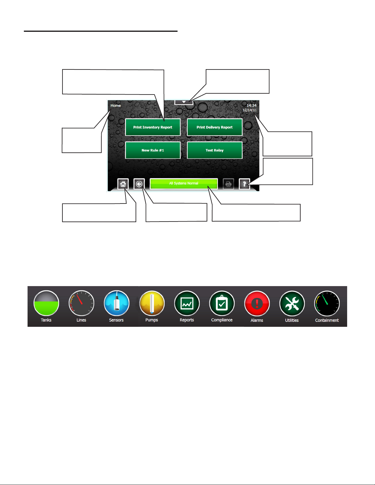
One-Touch Buttons – Run
customized and site-specic rules
for various console functions.
Shows which
screen is
displayed.
Home – This will return to
the screen shown here.
Back – Returns to
the previous screen.
Quick Jump Menu –
Allows rapid access
to console functions.
Shows current
system time and
date.
Help – Displays
context-sensitive
help information.
Status – When in Alarm, bar
turns red and describes alarm.
Navigation Buttons
There are many ways to navigate the applications of the TS-550 evo console. Listed below are buttons that will help you
navigate the functions of the console.
Quick Jump Menu (QJM)
The Quick Jump Menu was developed to simplify system navigation. From the Quick Jump Menu you can access sections
of the TS-550 evo with a few quick selections.
Quick Jump Menu
Note: Your console will display selections depending upon installed equipment.
Selecting the icon will take you to the summary screen for that item and allow you to access more detailed information.
13
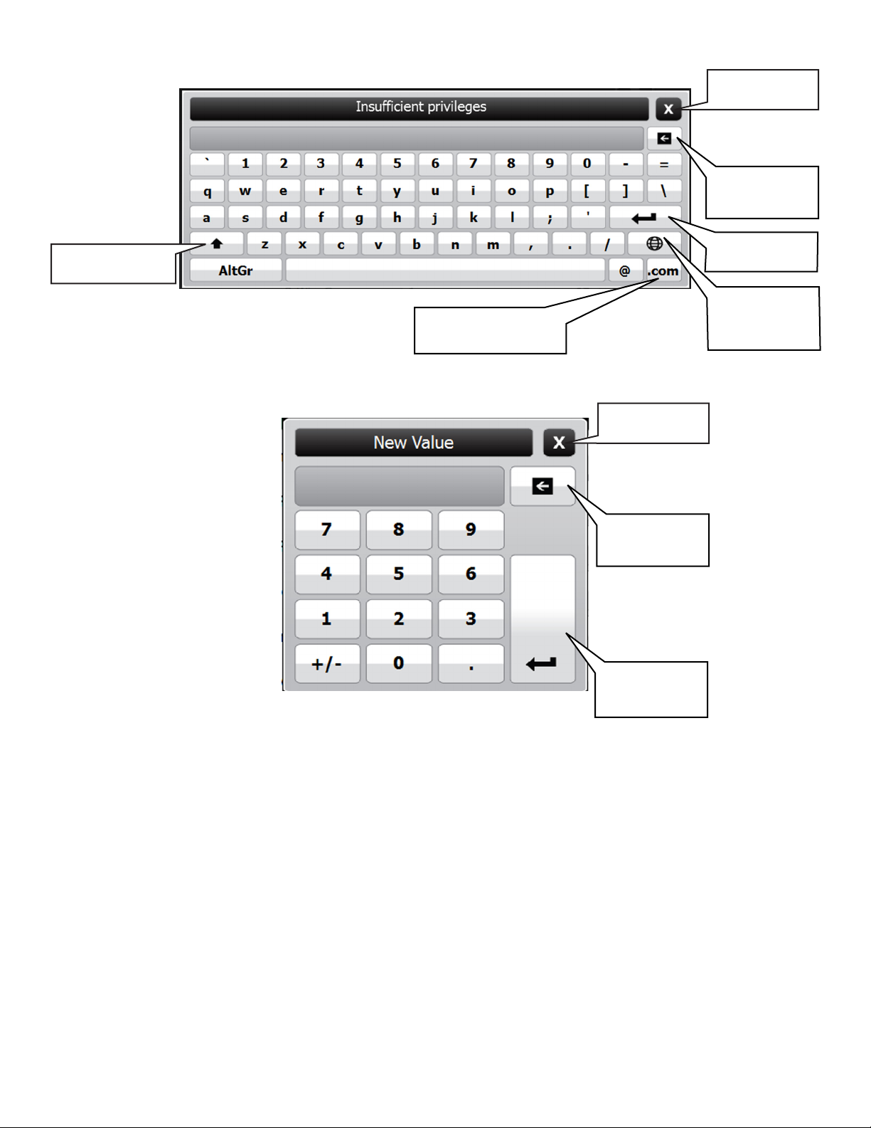
Text Entry Screen
Close Without
Saving
Erase Individual
Characters
Use Upper-Case
Characters
Number Entry Screen
Adds the .com extension
to an e-mail address
Save and Enter
Text
Use
International
Characters
Close Without
Saving
Erase Individual
Characters
Save and Enter
Numerals
14
Initial Console Conguration
Initial setup must be completed before the console can be
used. This section will show how to set custom parameters
by navigating through the programming options to set up
the TS-550 evo series console for the rst time.
Touch Screen Calibration
Calibrating the touch screen will enable the console to
better recognize the area that you “touch,” so that you can
accurately enter in information. The LCD touch screen is
calibrated at the factory when a system is built but it may
be necessary to re-calibrate occasionally. To calibrate the
touch-screen function of the display, you must rst access
the calibration application.
1. From any screen, press Quick Jump
Menu > Utilities > Tools > Touch Screen Calibration.
2. The console will ask if you are sure that you want
to proceed, answer Yes.
3. Follow the on-screen instructions to complete the
calibration process.
Console Build Characteristics
Each console is custom ordered and built to each
customer’s specications. That means that all of the
hardware (modules) and software options needed for your
site are installed and tested. Before programming, check
the status and version of each module and verify that your
purchased options are present.
Pressing QJM > Utilities > System will give you the
option to view specic details about the system
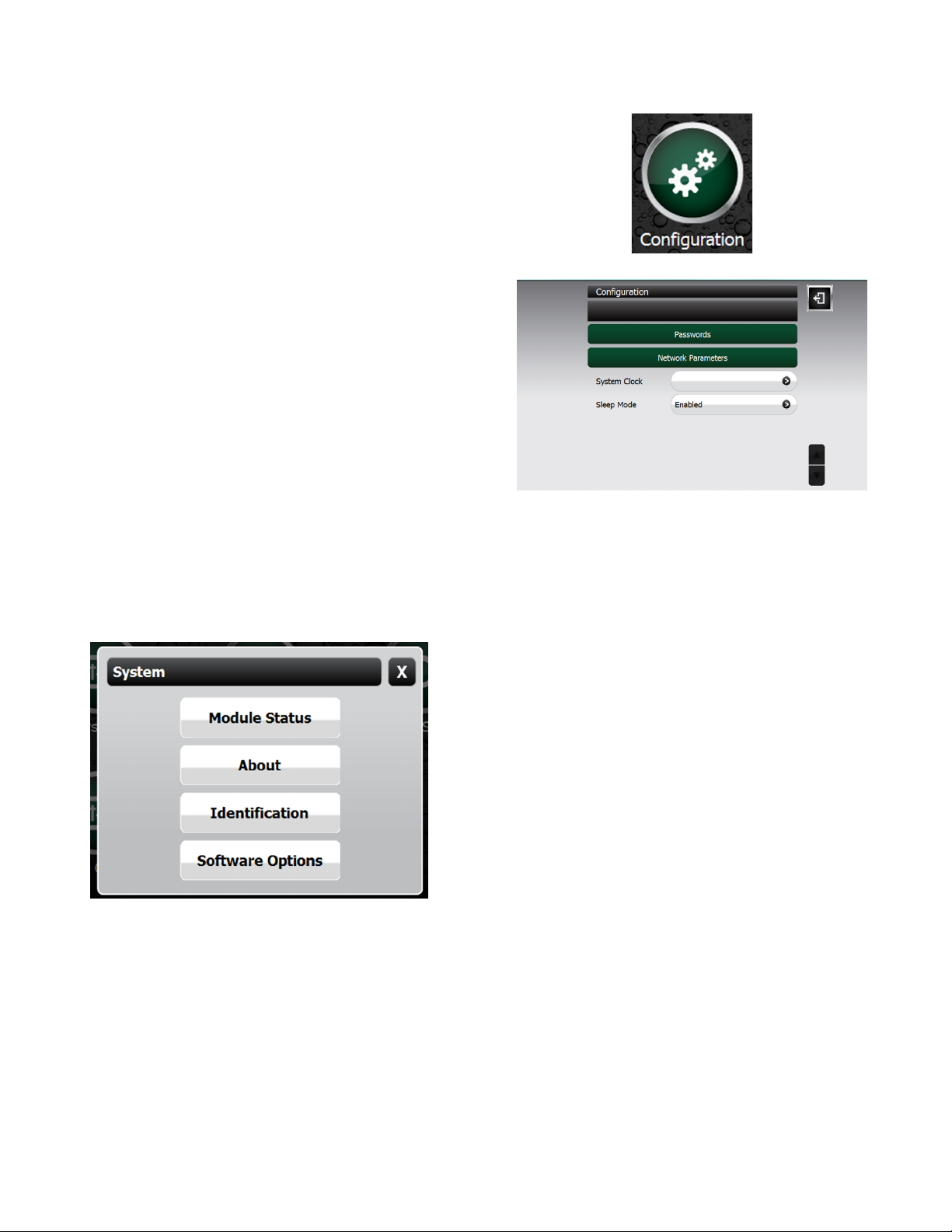
Setup Menu
From any screen select QJM > Utilities > Setup >
Conguration.
Conguration Options
Using the options in this menu, you can change:
• Passwords
• Protocol Settings
• Network Parameters
• System Clock
• Current time / date and set an accurate time zone.
• Toggle Sleep Mode
Modifying Passwords
For access control and security purposes, the console will
allow you to change any password used for accessing
console functions. When changing passwords, make note
of the password and keep it in a secure, memorable place.
The password you choose must be at least two characters
long with a maximum of 16 characters — spaces
and special characters are allowed as part of your
password.
Module Status - Lists the modules installed and what
version those modules are running. It will also indicate if
the module is operational or not.
About - Provides contact information for Franklin Fueling
Systems
Identication – View to locate the System Serial Number,
Ethernet Address (not the same as IP address), Controller
Serial number and Date / Time of manufacture.
Software Options – Displays the current installed
software options.
Administrator level access is required to change
passwords.
To modify passwords:
1. Press the Quick Jump Menu > Utilities > Setup >
Conguration > Passwords.
2. Select the access level to be changed
3. Enter the new password and press enter to accept
the change
Once the console has been powered up, navigate the
console by pressing the screen on the appropriate button.
1. From any screen select QJM > Utilities > Setup >
Conguration.
2. If prompted enter the administrator password.
3. Select from the options in the Network Parameters
section that follows to view or change console
conguration settings
.
15
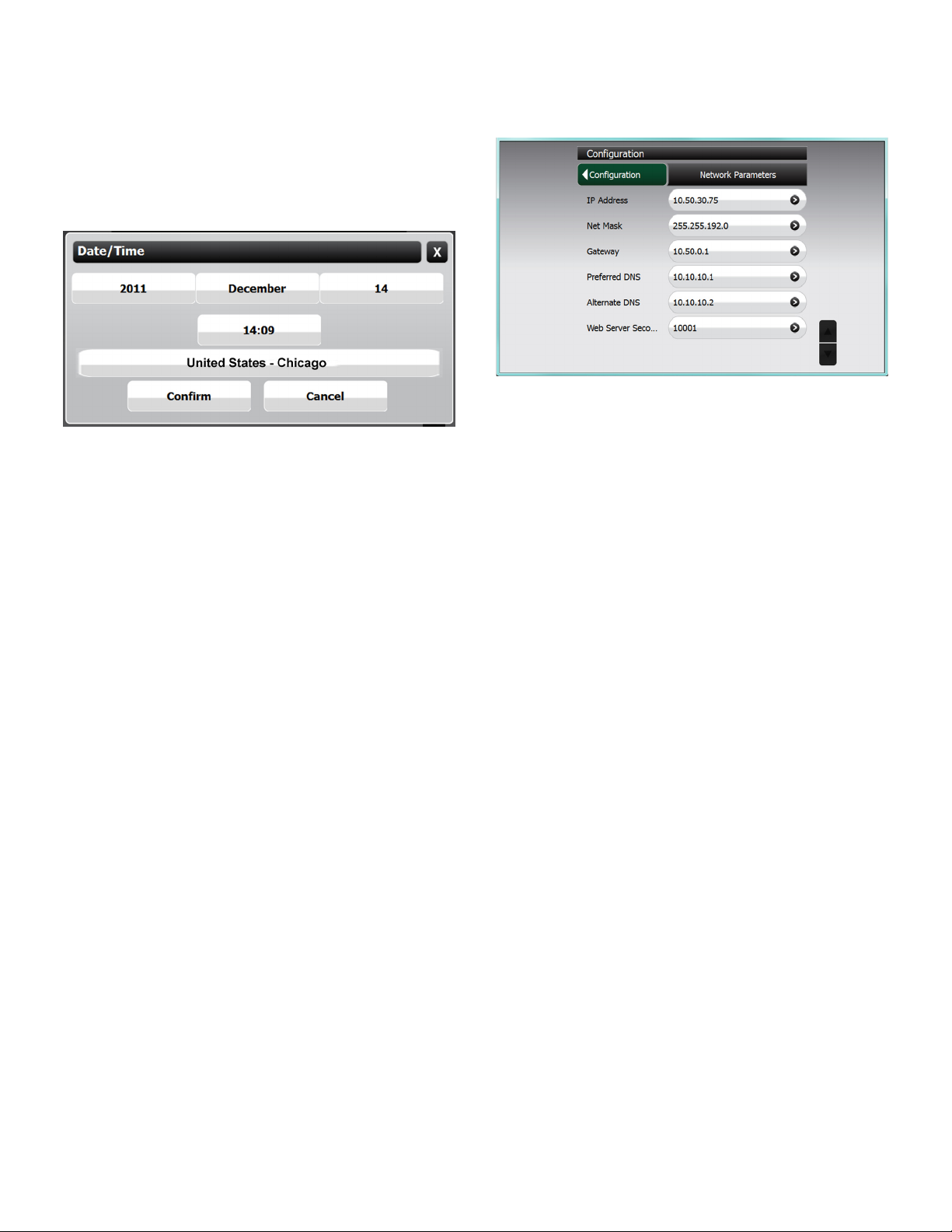
Date / Time Set
To set the date and time, click the button that corresponds
with your selection and then select the correct option from
the list. If your choice does not appear on the rst screen,
use the up and down navigation buttons to scroll through
more options. When nished, conrm your selection by
pressing the conrm button. It is important to enter the
date and time information correctly to ensure reports and
alarms can be accurately tracked.
Time Zone
Set the Time Zone according to your geographical location.
If your choice does not appear on the rst screen, use the
navigation up and down buttons to scroll through more
options. When nished, conrm your selection by pressing
the conrm button.
Toggle Sleep Mode
Enabling sleep mode allows the display to dim after 5
minutes.
Network Parameters
To communicate with your network equipment (i.e. router,
switch, hub, etc.) you will need to modify the network
parameters.
IP Address Settings:
IP Address – This is a logical (electronic) address, like a
street address, that the console uses to route
information. This address will have to match
your network, if connected to a network, in
order to ‘talk’ to a remote communication
device, or your PC.
Network Mask – Masking is a way to diversify the use
of multiple subnets. The mask must match
that of the network the console is connected
to. Masks are used in networking to create
‘sub-networks’ within a whole, like slicing and
apple. You have separate slices that may be
in different locations, but they are still from the
same apple. Administrators use this to make
separate networks, to maximize bandwidth or
capacity of medium resources (cables or ber).
Therefore, when your network uses static IP
addressing (assigned by an administrator),
this mask must match the Network Mask of the
router port that it is attached to. If the network
uses a DHCP server (automatically assigns
IP addresses) then the mask should meet the
specications set by your administrator.
Gateway – The Gateway is the logical address to the
nearest router port, commonly the one that
is connected to the console. Consult your
administrator for details on this and other
network parameters.
DNS Server Address:
Preferred DNS Server / Alternate DNS Server – The
domain name system (DNS) is the way that internet
domain names are located and translated into Internet
Protocol addresses. A domain name is a meaningful and
easy-to-remember tag for an internet address (used for
e-mail functions).
16

Programming System Parameters
To program the system parameters select QJM > Utilities
> Setup > Parameters.
Preferences
Use the Preference tables on the following pages to select
the menu options to be changed.
Language
Language Options
English
Spanish
Portuguese
Italian
Russian
French
Hindi
Hebrew
Polish
Bulgarian
Slovakian
Turkish
German
Chinese (Simplied)
Chinese (Traditional)
Date / Time
Date/Time Options
MM/dd/yyyy
M/d/yyyy
M/d/yy
Short date format
MM/d/yy
MM/dd/yy
Yy/MM/dd
yyyy-MM-dd
dd-MMM-yy
Symbol Representation
MM
M
Two-digit month with leading zero (i.e. 01 for
Jan…).
Two-digit month, no leading zero (i.e. 1 for
Jan…).
MMM Three-letter month (i.e. JAN, FEB, AUG…).
dd
Two-digit day with leading zero (i.e. 01,
02…).
d Two-digit day, no leading zero (i.e. 1, 2…).
yyyy Four-digit year (i.e. 2006…).
yy Two-digit year (i.e. 06, 07…).
HH
hh
Two-digit hour with leading zero; 24-hour
format.
Two-digit hour, no leading zero; 24-hour
format.
mm Two-digit minute, with leading zero.
ss Two-digit second, with leading zero.
a A.M. or P.M. indicator.
EEEE
Numbers
Numbers Options
Digit
grouping
Digit
grouping
symbol
Decimal
symbol
Display
leading
zeroes
Group digits by 103 using specied symbol
(i.e. either “123456789” or “123,456,789”).
Symbol used to group digits (i.e. ‘, ’; ‘ _ ‘…).
User dened option.
Symbol used to separate decimal units (i.e.
‘.’; ‘,’). User dened option.
Displays decimals with leading zero (i.e.
with ‘0.123’; without ‘.123’).
Long date format
Year/month date format
Short time format
Long time format
EEEE, MMMM dd, yyyy
MMMM dd, yyyy
EEEE dd MMMM, yyyy
dd MMMM, yyyy
MMMM, yyyy
HH:mm
H:mm
hh:mm a
h:mm a
HH:mm:ss
H:mm:ss
hh:mm:ss a
h:mm:ss a
17
 Loading...