


TS-550
Fuel Management System
Operator’s Guide
TS-550 evo
Franklin Fueling Systems • 3760 Marsh Rd. • Madison, WI 53718 USA
Tel: +1 608 838 8786 • 800 225 9787 • Fax: +1 608 838 6433 • www.franklinfueling.com

Notice
Franklin Fueling Systems (FFS) reserves the right to change this document and specications at any time without notice.
FFS makes no expressed or implied warranty with regard to the contents of this manual. FFS assumes no liability for
errors or omissions, or for any damages, direct or consequential, that may result from the use of this document or the
equipment that it describes.
Trademarks
INCON®, TS-550 evo, Tank Sentinel®, System Sentinel®, SCALD®, Brite®, BriteBox®, BriteBus®, and BriteSensors® are
registered trademarks of Intelligent Controls. All brand and product names are trademarks or registered trademarks of
their respective companies.
Inspection of Materials
Visually inspect all components for defects or damage prior to installation. If any defect or damage is found, do not use the
product and contact FFS for further assistance.
Return Shipping Charges
FFS will not accept shipments of returned products without a Return Material Authorization (RMA) number. RMA’s are
obtained by contacting FFS’s Technical Service division — NO RMA’s will be given without the unit’s serial number(s).
Returned material remains the property of the buyer until replaced or repaired.
Contacting Franklin Fueling Systems (FFS)
Please feel free to contact us by mail at:
Franklin Fueling Systems
3760 Marsh Rd.
Madison, WI 53718 USA
Or contact us by phone, fax or e-mail:
Tel: 1 608 838 8786 E-mail: sales@franklinfueling.com
Fax:
1 608 838 6433 techserve@franklinfueling.com
Tel:
US & Canada 1 800 225 9787
Tel: México 001 800 738 7610
Tel: Europa +49 6571 105 380
Ofce Hours: 8am to 5pm CST - Monday through Friday
Technical Service Hours: 7am to 7pm CST - Monday through Friday
Please visit our web site at www.franklinfueling.com
No part of this publication may be reproduced in any form without the prior written consent of FFS. All rights reserved.
ii
Copyright ©2007 by Franklin Fueling Systems (FFS).

Contents
Important Safety Messages
Approvals ................................................................................................................................2
Related Documentation .......................................................................................................... 2
............................................................ 1
Introduction ...................................................................................... 3
Denitions and Acronyms .............................................................................................................. 3
Applications ............................................................................................................................4
System: ......................................................................................................................................... 4
Fuel Management System (FMS): ................................................................................................ 4
Secondary Containment Monitoring (SCM): ................................................................................. 4
Standard Sensors.......................................................................................................................... 4
BriteSensors™ ........................................................................................................................ 4
Modules ......................................................................................................................................... 4
Standard Modules ......................................................................................................................... 4
Optional Modules .......................................................................................................................... 5
User Interface ................................................................................................................................ 5
Alarms and Warnings .................................................................................................................... 5
Programming and Navigation ........................................................ 6
Console Navigation ................................................................................................................. 6
Navigation Buttons ........................................................................................................................ 6
Quick Jump Menu (QJM) .............................................................................................................. 6
User Role - Access Control .....................................................................................................7
System Identication ............................................................................................................... 7
Quick Jump Menu Selection Description ................................................................................ 8
Tank Inventory Summary Screen .................................................................................................. 8
Tank Inventory Detail Screen ........................................................................................................ 8
Line Status Summary Screen ....................................................................................................... 8
Line Status Detail Screen .............................................................................................................. 9
Sensor Status Summary Screen .................................................................................................. 9
Sensor Status Detail Screen ......................................................................................................... 9
Pump Status Summary Screen ................................................................................................... 10
Pump Status Detail Screen ......................................................................................................... 10
Report Generator Screen ............................................................................................................ 10
Compliance Screen ......................................................................................................................11
Tank Compliance Screen .............................................................................................................11
Alarm Summary Screen ...............................................................................................................11
Active Alarm Detail Screen ...........................................................................................................11
Utilities Screen ............................................................................................................................ 12
Conguration Menu ..................................................................................................................... 12
Secondary Containment Status Summary Screen ...................................................................... 13
Secondary Containment Detail Screen ....................................................................................... 13
Printing Reports .................................................................................................................... 14
Internal Printer ............................................................................................................................. 14
External Printers .......................................................................................................................... 14
Reports Options .......................................................................................................................... 14
Tank Testing ..................................................................................... 15
Why Test the Integrity of a Tank .................................................................................................. 15
Static Testing ............................................................................................................................... 15
Tank Testing Requirements ......................................................................................................... 16
Ideal Testing Conditions .............................................................................................................. 16
How to Manually Start Static Tests ....................................................................................... 16
Static Test Results ....................................................................................................................... 16
Statistical Continuous Automatic Leak Detection (SCALD) ................................................. 17
Why Continuously Test Tank Integrity ......................................................................................... 17
SCALD Testing Requirements ..................................................................................................... 17
When SCALD Tests ..................................................................................................................... 17
SCALD Results ........................................................................................................................... 17
Tank Leak Test Reports ........................................................................................................18
Printing Tank Leak Test Reports .................................................................................................. 18
iii

Line Leak Testing ............................................................................ 21
Overview ...............................................................................................................................21
Line Leak Testing Requirements ................................................................................................. 21
Test Cycles & Types .............................................................................................................. 22
How to Manually Start Line Leak Tests ................................................................................. 22
Line Test Results ......................................................................................................................... 23
Line Leak Test Reports ................................................................................................................ 23
Printing Tank Leak Test Reports .................................................................................................. 23
Web Browser Interface ................................................................... 24
How to Manually Start Leak Tests Using Web Browser Interface ......................................... 25
Routine Maintenance ...................................................................... 26
Console Care ........................................................................................................................26
LCD Touch Screen ................................................................................................................ 26
Calibration ................................................................................................................................... 26
Internal Printer ...................................................................................................................... 26
List of Alarms and Troubleshooting .............................................. 27
System Alarms ...................................................................................................................... 27
FMS Alarms .......................................................................................................................... 29
SCM Alarms .......................................................................................................................... 32
Wire Sensor Alarms .............................................................................................................. 33
Line Leak Detector (LLD) Alarms ..........................................................................................34
TPI Alarms ............................................................................................................................ 35
Printer Alarms ....................................................................................................................... 35
Appendix C – Third Party Certications ........................................ 36
iv
Important Safety Messages
Franklin Fueling Systems (FFS) equipment is designed to be installed in association with volatile hydrocarbon liquids
such as gasoline and diesel fuel. Installing or working on this equipment means working in an environment in which these
highly ammable liquids may be present. Working in such a hazardous environment presents a risk of severe injury or
death if these instructions and standard industry practices are not followed. Read and follow all instructions thoroughly
before installing or working on this, or any other related, equipment.
As you read this guide, please be aware of the following symbols and their meanings:
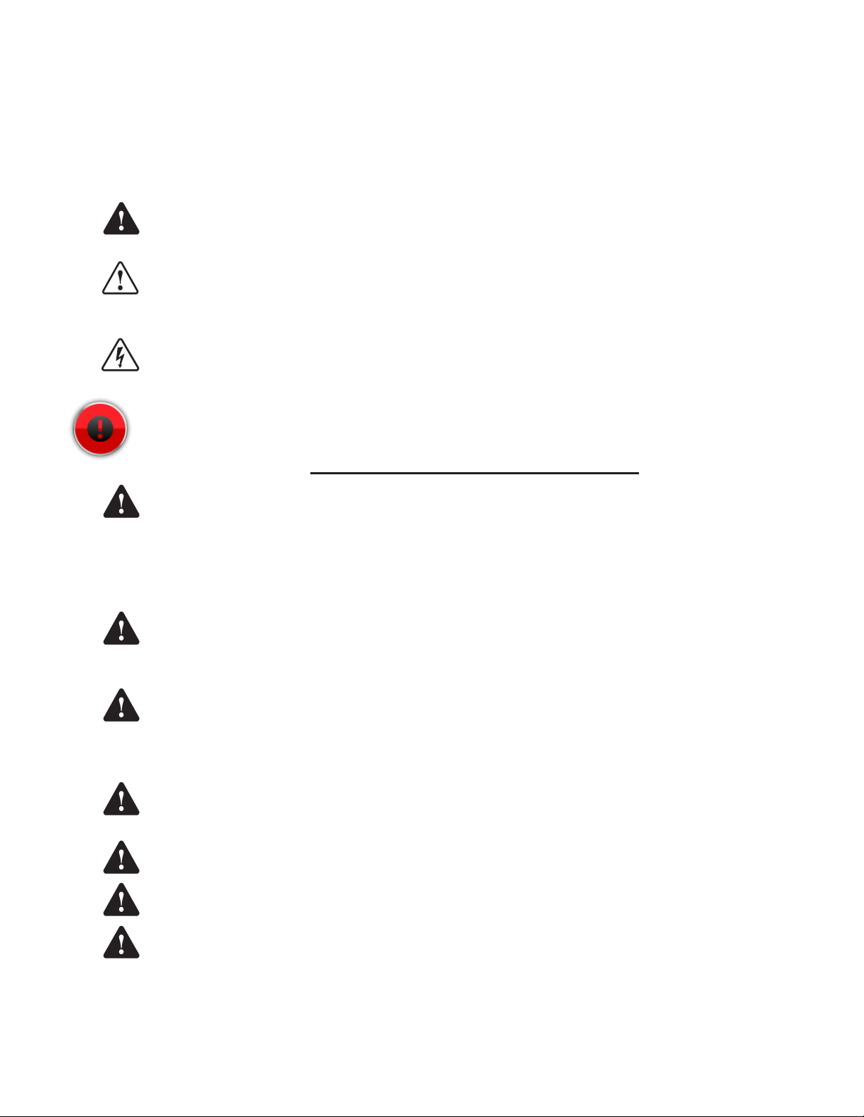
Warning
Caution
Danger
Warning
Warning
This symbol identies a warning. A warning sign will appear in the text of this document when a potentially
hazardous situation may arise if the instructions that follow are not adhered to closely. A potentially hazardous
situation may involve the possibility of severe bodily harm or even death.
This is a caution symbol. A caution sign will appear in the text of this document when a potentially hazardous
environmental situation may arise if the instructions that follow are not adhered to closely. A potentially
hazardous environmental situation may involve the leakage of fuel from equipment that could severely harm
the environment.
This symbol identies an electrical danger. An electrical danger sign will appear in the text of this document
when a potentially hazardous situation involving large amounts of electricity may arise if the instructions that
follow are not adhered to closely. A potentially hazardous situation may involve the possibility of electrocution,
severe bodily harm, or even death.
Alarms and warnings are designed to alert you with specic details when a problem occurs so you can take
appropriate corrective action.
Follow all applicable codes governing the installation and servicing of this product and the entire system.
Always lock out and tag electrical circuit breakers while installing or servicing this equipment and any
related equipment. A potentially lethal electrical shock hazard and the possibility of an explosion or re from
a spark can result if the electrical circuit breakers are accidentally turned on during installation or servicing.
Please refer to the Installation and Owner’s Manual for this equipment, and the appropriate documentation
for any other related equipment, for complete installation and safety information.
Follow all federal, state and local laws governing the installation of this product and its associated systems.
When no other regulations apply, follow NFPA codes 30, 30A and 70 from the National Fire Protection
Association. Failure to follow these codes could result in severe injury, death, serious property damage
and/or environmental contamination.
Warning
Warning
Warning
Warning
Warning
Always secure the work area from moving vehicles. The equipment in this manual is usually mounted
underground, so reduced visibility puts service personnel working on this equipment in danger from moving
vehicles entering the work area. To help eliminate these unsafe conditions, secure the area by using a
service truck to block access to the work environment, or by using any other reasonable means available to
ensure the safety of service personnel.
When the Fuel Management System is used to monitor tanks containing gasoline or other ammable
substances, you may create an explosion hazard if you do not follow the requirements in this manual
carefully.
All wiring must enter the console’s enclosure through the designated knockouts. An explosion hazard may
result if other openings are used.
You must run wiring from probes or sensors to the Fuel Management console in conduits which are
separate from all other wiring. Failure to do so will create an explosion hazard.
Substituting components could impair intrinsic safety. T5 series consoles are intrinsically safe for sensors
installed in – Class I, Division 1, Group D – hazardous locations. Substitution of components could make
the energy limiting circuitry in the system ineffective and could cause an explosion hazard. Repairs to a T5
series console or attached components should only be performed by a qualied, factory-trained technician.
1

Certied Programmer/Service Person: Only a Franklin Fueling Systems certied programmer or service person is
allowed to access both the user interface keypad and areas internal to the Fuel Management System console.
Station Owner/Operator: The station owner or operator of the Fuel Management System console is only allowed to
access the user interface keypad. Access to areas internal to the console is strictly prohibited.
Approvals
All Fuel Management System models are UL and cUL listed 6L79 as Liquid Level Gauge / Leak Detection
Systems. Third party approved leak detection — Pd (probability of detection) = 99.2 % for 0.1 or 0.2 GPH leak
tests (0.1 = annual precision test, 0.2 is the monthly regulatory compliance test).
*The static tank test does not support Manifolded tanks.
**SCALD is 3rd party approved for ONLY two Manifolded tanks.
Related Documentation
The system installation and programming instructions are provided for your use in separate documents. Detailed
installation and testing instructions for each type of leak detection sensor are present in the relevant manual, and,
likewise, the installation, testing and programming of various upgrade kits and optional accessories are also contained in
separate manuals, addenda or in one of this document’s appendices.
TS-550 evo Series Fuel Management Systems Installation Guide (000-2170)
TS-550 evo Series Fuel Management Systems Programming Manual (000-2173)
Manuals can be found on-line at: http://www.franklinfueling.com/service/docs.asp
2

Introduction
The purpose of this manual is to guide installers, operators and technicians through the operation of a TS-550 evo
console. The TS-550 evo console incorporates the monitoring and alarm capabilities of preceding automatic tank gauges
with advanced technologies to supply tank and level data more accurately and efciently. This manual is also designed to
introduce technicians to the optional LCD Graphical User Interface, which is used as an input device to program system
conguration and maintain all applications from the front panel of the console. Overall safety issues, troubleshooting
information, start-up procedures, warranty, service and return policies, as dened in this manual, must be followed.
The TS-550 evo Fuel Management System consists of an open architecture, modular console that can run multiple Fuel
Management Applications simultaneously. It typically contains a color LCD touch screen user interface and a built-in
printer, but it can also be operated by a web-based remote interface. Magnetostrictive Liquid Level Probes inside of
the tanks provide the console with inventory and leak detection information. A variety of optional sensors can be used
to monitor containment spaces. TS-550 evo series consoles combine the power and exibility of computer-based open
architecture with a high speed modular bus design.
Denitions and Acronyms
AST
– Aboveground Storage Tank
Console – The enclosure that houses the Modules.
DHI – Dispenser Hook Isolation
DW/DWT – Double Wall/Double Wall Tank
FAST – Franklin Auto Setup Tool
FMS – Fuel Management Systems
IS – Intrinsically Safe
LCD – Liquid Crystal Display
LON – Echelon Communication Module
LLD – Line Leak Detection
Module – A plug-in card within a T5 series console that is
used to perform various functions for a console.
Modules are used for eld wiring the input and/
or output of electrical signals between different
functional equipment pieces.
NWGLDE – The National Work Group Leak Detection
Evaluations
OTB – One Touch Button
QTB – Quick Jump Button
PC – Personal Computer
STP – Submersible Turbine Pump
TS-ACI – 12 input, AC Input Module
TS-DIMIB – Dispenser Interface Module
TS-2WSNS – 12 input, 2-Wire Sensor Module (Intrinsically
Safe)
TS-3WSNS – 8 input, 3-Wire Sensor Module (Intrinsically
Safe)
TS-420IB – 4-20mA Analog Input Module (Intrinsically
Safe)
TS-RLY – Relay Module
TSSP-CM – Controller Module
TS-PRB – Probe Module (Intrinsically Safe)
TSSP-PS – Power Supply Module
TPI – Turbine Pump Interface
TS-EMS – Environmental Monitoring System
TS-EXPC – Expansion Console
USB – Universal Serial Bus
UST – Underground Storage Tank
XML – eXtensible Markup Language
RS-232 – An EIA standard for serial communication using
either a 9 or 25-pin connector or adapter.
RS-485 – An EIA standard for serial communication.
RTD – Resistance Temperature Detector
RJ-45 – An EIA standard connector for use in
communications with an eight conductor cable.
Usually used in data transmission applications.
RJ-11 –
An EIA standard connector for use in
communications using STP wiring. Usually used in
voice and fax applications.
3

Applications
Applications are programs designed to function as a
platform for specic Inputs/Outputs. There are three
different applications available to the TS-550 evo console:
System:
This application is standard on all systems and monitors
the console’s operational status and manages software
options and upgrades. All preferences and conguration
settings are controlled by this application (e.g., display
options, clock and calendar). The system application is
standard on every console.
Fuel Management System (FMS):
The Fuel Management System application provides
inventory management and leak detection for tanks, lines
and sensors as well as tank, line and sensor control. This
application also allows users to print reports, tank tests
and line tests.
A broad range of liquid products can be leak-tested and
inventory-monitored using Magnetostrictive LL2 probes.
These probes come in a variety of lengths and typically
contain two oats for indicating both product and water
levels inside the of tank. Programmable limits can be set to
indicate high and low conditions.
Containment sumps, interstitial spaces, monitoring
wells and other areas can be monitored for water and
hydrocarbon intrusion using a wide range of optional
Standard and BriteSensors. These sensors come in 2-wire
(non-discriminating) and 3-wire (typically discriminating)
versions. These models are listed below and can be used
in any combination depending on site specications.
Secondary Containment Monitoring (SCM):
Secondary Containment Monitoring is a continuous
secondary containment monitoring system that monitors
the interstitial spaces of double walled tanks and sumps,
secondarily contained product and vapor return piping.
SCM is a software option that can be added to the TS-550
evo. The Secondary Containment Control Module (SCCM)
consists of a vacuum sensor, solenoid valve, mechanical
bypass valve, and vacuum manifold. SCM uses the
STP siphon port vacuum to evacuate the containment
space and AutoLearn® technology to determine the
characteristics of each secondary containment area that is
monitored. The SCCM unit comes in two models.
Standard Sensors
Standard sensors do not discriminate between liquid and
hydrocarbons and are typically 2-wire sensors.
TSP-EIS – Electro-optic Interstitial Sensors (3-wire,
infrared, liquid sensor)
TSP-HLS – High product Level Sensor (2-wire, oat
switch, liquid level sensor)
TSP-ULS – Universal Liquid Sensor (2-wire, oat switch,
liquid level sensor)
BriteSensors™
BriteSensors™ are 3-wire, discriminating sensors (many of
which may generate multiple alarms).
TSP-DIS – Discriminating Interstitial Sensor (Electro-optic
and conductivity, liquid sensor)
TSP-HIS – Hydrostatic Interstitial Sensor (oat switches,
Brine sensor)
TSP-DDS – Discriminating Dispenser sump Sensor
(conductivity strip and oats, liquid and vapor sensor)
TSP-DTS – Discriminating Turbine sump Sensor
(conductivity strip and oats, liquid and vapor sensor)
TSP-MWS – Discriminating ground water Monitoring
Well Sensor (oat and conductivity strip, liquid and vapor
sensor)
TSP-DVS – Discriminating Vapor well Sensor (vapor
sensor)
TSP-DMS - Discriminating Magnetostrictive Sensor
Modules
A modular bus consists of modules connected by a bus
backplane. Some modules are standard in all units, while
the type and number of other modules are dependent
on the site conguration and options purchased. Most
systems have empty slots available for future expansion or
can be expanded with an expansion console.
Standard Modules
Controller Module
Contains the primary controller and software applications
as well as the user interface and printer controls. The
module contains the Ethernet port, (2) USB ports, COMM
port 1, audible horn and an optional internal modem card.
Power Supply Module
Contains a self-switching (110 & 220 VAC) input and
provides power to the rest of the system. the module
contains two output relays, two backup generator inputs,
a Turbine Pump Interface (TPI) RS-485 connection and
the COMM 2 communications port. An optional Dispenser
Interface Module (TS-DIMIB) or Echelon Communications
Module (TS-LON) can also be added. The Power Supply
Module also has a bus expansion port that can connect a
TS-550 evo console to a TS-EXPC Expansion Console.
4
Optional Modules
2-Wire Sensor Module Provides 12 inputs for 2-wire
Standard sensors.
3-Wire Sensor Module Provides 8 inputs and
supports both 3-wire and
2-wire sensors.
4-20 mA Input Module Provides 8 inputs that can be
used for TS-LS500 line leak
detection transducers and
SCM vacuum transducers.
4-20 mA EXP Explosion-proof module.
Otherwise the same as the
4-20 mA Input Module.
AC Input Module Provides 12 inputs for
dispenser hook signals, which
are also required for LLD. This
module replaces external DHI
boxes.
Probe Module Provides 12 inputs or LL2
probes.
User Interface
LED Indicators – Three LEDs below the front panel give
an “at-a-glance” indication of the system status. These
LEDs are standard on all systems. The green Power LED
indicates that the system power is on. The yellow Warning
LED gives indication that the console has detected a
malfunction or condition that has been deemed a Warning.
The red Alarm LED indicates that the system has detected
an alarm condition.
LCD Touch Screen – The color LCD touch screen is
the most commonly used user interface for the Fuel
Management System. This bright and colorful display
allows easy viewing in any lighting condition. Touching
certain buttons or segments of the screen will allow access
to menus or more detailed information. Do not use sharp
or pointed objects to operate the touch screen or damage
may result. A “Sleep Mode” screensaver can be activated
under Setup / Conguration / Sleep mode to automatically
turn off the back light after 5 minutes to extend the life of
the display. If improper operation of the touch screen is
noted, it may be necessary to calibrate the touch screen.
Please refer to the Routine Maintenance chapter of this
manual for calibration procedures.
Relay Module Provides 8 relay outputs (2-
Amp) which are typically used
to control the submersible
pump relays to provide pump
or dispenser shutdown when
line leak detection or other
applications are used. Not
used in combination with TPI.
10-Amp Relay Module Provides 6 relay outputs which
are typically used to control
the submersible pump relays
to provide pump or dispenser
positive shutdown upon alarm
conditions.
Input / Output Module Provides 8 AC or DC voltage
inputs that can range from 3
to 240 volts. Typically used for
vapor processors and generic
devices, but not for dispenser
hook signals. In addition, this
module also includes four
4-20 mA signal outputs which
are typically used to interface
to an external device, such
as a SCADA (Supervisory
Control and Data Acquisition),
building monitoring system or
fuel level monitoring.
Alarms and Warnings
Alarms and warnings are designed to alert you with
specic details when a problem occurs so that you can
take appropriate corrective action. System hardware
failure warnings, tank related alarms, leak detection sensor
alarms, and line leak alarms will always notify the user in
certain ways, other notication options are programmable.
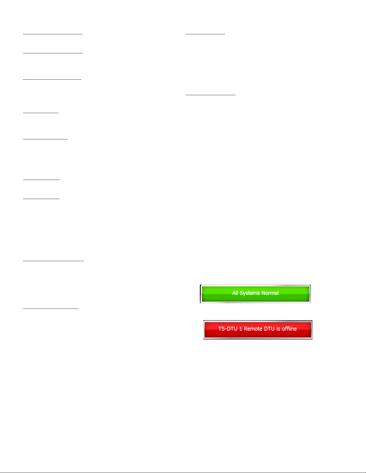
Alarms and Warnings will always:
• Cause the red Alarm light or yellow Warning light to
ash (standard).
• Change the alarm button from showing normal:
to showing the alarm. i.e.:
.
Optionally, on alarm the system can:
• Sound the console’s internal alarm horn.
• Activate relay outputs and sound external alarm
devices.
• Print alarm reports.
• E-mail alarm reports to a specied destination.
• Notify remote monitoring software via optional
internal modem or Ethernet.
For help with troubleshooting alarms, refer to the
Troubleshooting chapter of the TS-550 evo Series
Programming Manual (000-2173).
5
Programming and Navigation
Console Navigation
The operating system is designed for easy navigation. Applications allow the user to modify programming options by
responding to on-screen commands. The following instructions show various operating system functions, so that issues
can be corrected efciently without interrupting dispensing or sales.
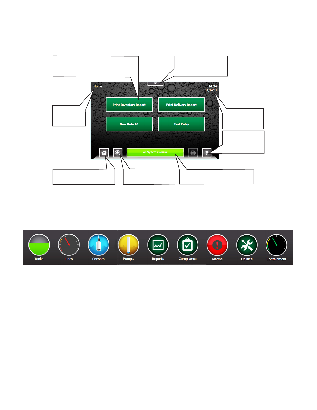
One-Touch Buttons – Run
customized and site-specic rules
for various console functions.
Shows which
screen is
displayed.
Home – This will return to
the screen shown here.
Navigation Buttons
There are many ways to navigate the applications of the TS-550 evo console. Listed below are buttons that will help you
navigate the functions of the console.
Back – Returns to
the previous screen.
Quick Jump Menu –
Allows rapid access
to console functions.
Shows current
system time and
date.
Help – Displays
context-sensitive
help information.
Status – When in Alarm, bar
turns red and describes alarm.
Quick Jump Menu (QJM)
The Quick Jump Menu was developed to simplify system navigation. From the Quick Jump Menu you can access sections
of the TS-550 evo with a few quick selections.
Quick Jump Menu
Note: Your console will display selections depending upon installed equipment.
Selecting the icon will take you to the summary screen for that item and allow you to access more detailed information.
Tank
s – The Tanks selection provides inventory information and control functions for the tanks and manifolds at a site
Lines – The Lines selection provides Line Status, Line Leak Test status, as well as Line control & calibration functions for
each line at a site.
Sensors – The Sensors selection provides Sensor status, and control functions for the sensors at a site.
Pumps – The Pump selection provides the status and control functions for all Pumps connected to the system using the
Turbine Pump Interface.
Reports – The Reports selection allow the user to generate any number of system and application reports.
Compliance – The Compliance selection provide detailed information regarding the compliance status of: Tanks, Manifolds,
Lines, and Sensors monitored by the system.
Alarms – The Alarms selection provide a list of current active alarms, as well as an alarm history and an application event
history.
Utilities – The Utilities selections provides access to the various setup, conguration, and system tools used to congure and
maintain the site.
• Page 8 list further information about these menu items
6
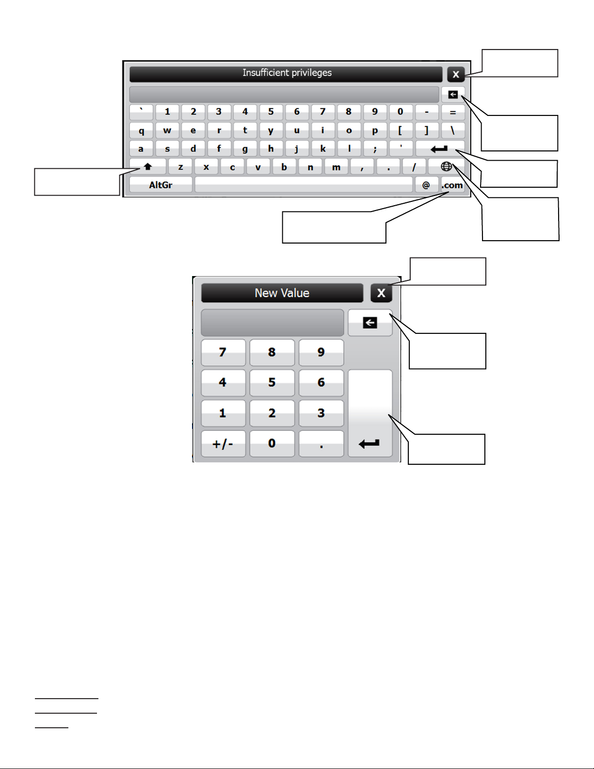
Text Entry Screen
Close Without
Saving
Erase Individual
Characters
Use Upper-Case
Characters
Number Entry Screen
Adds the .com extension
to an e-mail address
Save and Enter
Text
Use
International
Characters
Close Without
Saving
Erase Individual
Characters
Save and Enter
Numerals
User Role - Access Control
There are three levels of access into the console’s operating system: Guest, User, and Administrator. Each level will
allow an operator to access different features and controls of the console. This security feature prevents unauthorized
access to critical information and settings. The password for each access level can be adjusted by the Administrator. The
Administrator level is typically reserved for an Franklin Fueling Systems certied technician. User’s will be automatically
prompted for a password to access or change data as required.
The User Role icon displays the current access level allowed. White bars displayed in this icon indicate the access level.
Pressing the User Role indicator on your LCD display will return the system to Guest access level.
GUEST level: Guests are allowed to access menu options, check the system conguration and print reports. A GUEST
will not be able to modify the console’s settings.
USER level: Users are given access to more functions of the operating system so that they can perform line/tank leak
tests and reset line alarms.
ADMINISTRATOR: This level grants access to all areas of programming and setup conguration. The administrator
privilege is usually reserved for Franklin Fueling Systems certied technicians.
System Identication
In order to understand what sections of this manual apply to your system, you must be able to identify what Fuel
Management System you have and what Options and Applications it is running.
Model Number – Located on the front of the console.
Serial Number – Located on a sticker on the left side panel (along with Model number).
Options – To see what Applications and Options the system is running, press QJM>Utilities>System
7
Quick Jump Menu Selection Descriptions
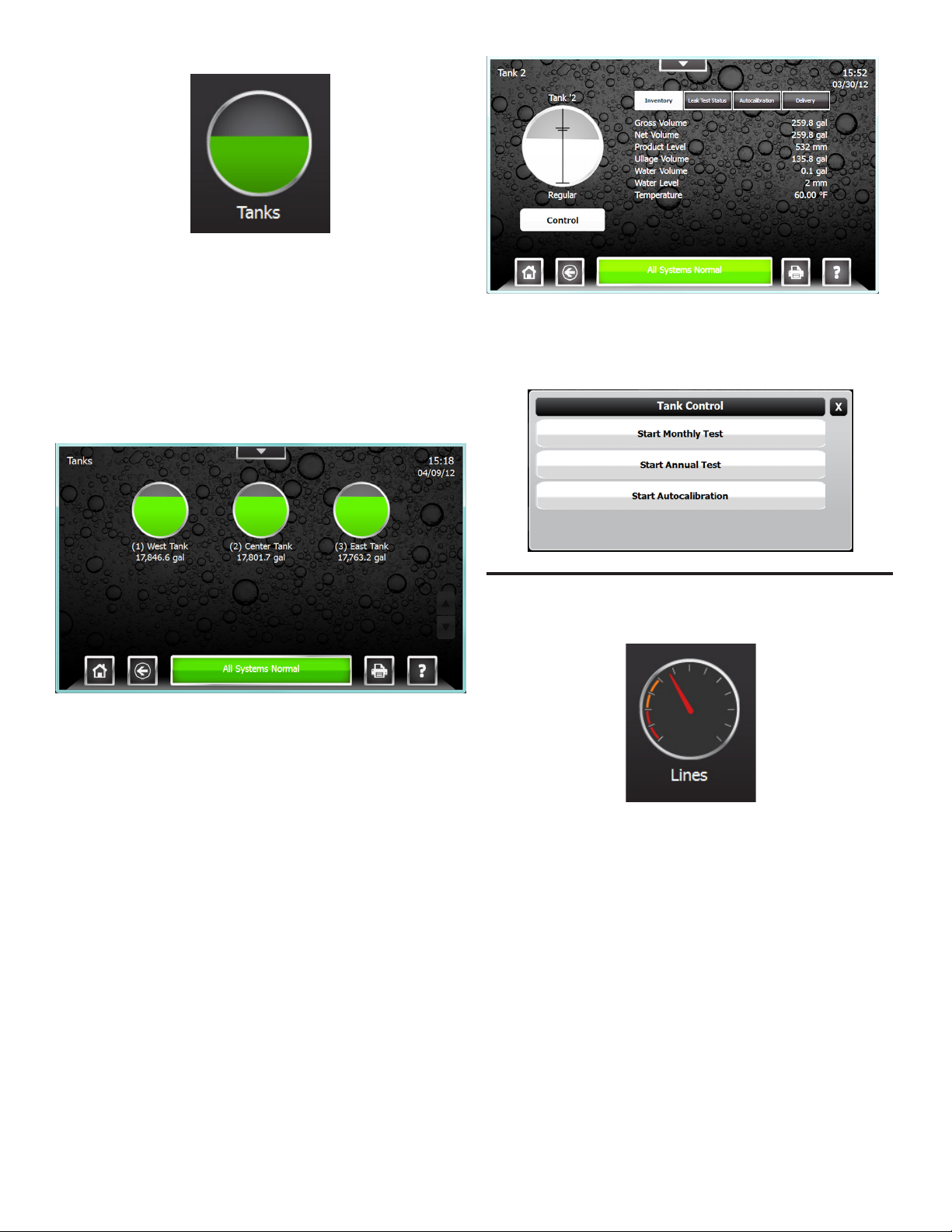
Tank Inventory Summary Screen
The Tank Inventory Summary screen displays a
graphical representation of the product and water levels in
the tanks and indicates any alarm conditions. The Product
name and current Volume are also displayed for each tank.
An alarm condition on the tank is also indicated here, if
present. Pressing the print button while on this screen will
print an Inventory Report for all tanks.
To access the Tank Inventory Summary screen select
Tanks from the Quick Jump Menu (QJM).
Tank Controls feature can be accessed using the Control
Button on the Tank Inventory Detail Screen. This will allow
authorized users and technicians to start tank tests or
autocalibration.
Tank Inventory Detail Screen
The Tank Inventory detail screen will provide detailed
information on product volume, level, temperature and
ullage space available in a particular tank. The level and
volume of any water will also be displayed. The hash
marks on the graphic indicate the various programmed
high and low alarm limits. An alarm condition on the tank is
also indicated here, if present.
The Tank Inventory Detail screen also provides details
regarding the tanks Static Leak Test status, Autocalibration
status, and Delivery history using the four tabs at the top of
the left hand column. Pressing the print button while on the
page will print an Inventory Report for just this tank.
To access the Tank Inventory Detail Screen select a tank
from the Tank Inventory Summary screen.
Line Status Summary Screen
The Line Status Summary screen displays a graphical
representation of the line pressures in each line and will
indicate any alarm conditions. The Line name and current
pressure reading are also displayed for each line.
To access the Lines Status Summary screen select Lines
from the Quick Jump Menu (QJM).
8
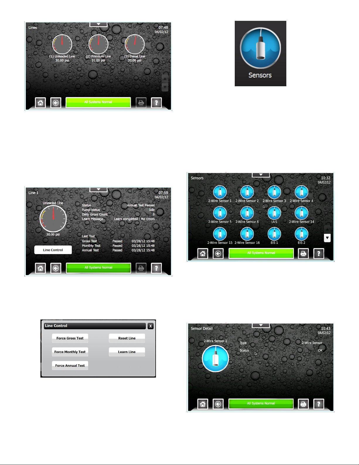
Line Status Detail Screen
The Line Status Detail screen will provide detailed
information on Line Leak Testing and the Line Status. The
Line status, Pump status, number of Gross Leak Tests
performed, Line Learn Messages, and the date and time
of the last line test completed. An alarm condition on the
Line is also indicated here, if present. From the Line Detail
screen Line Control can be accessed. To access the Line
Status Detail Screen select a line from the Line Status
Summary screen.
Sensor Status Summary Screen
The Sensor Status Summary screen displays a graphical
representation of a sensor, the name of the sensor and
will indicate any alarm conditions. Pressing the print button
from the screen will print a sensor status report for all of the
sensors.
To access the Sensor Status Summary screen select
Sensors from the Quick Jump Menu (QJM).
Line Controls feature can be accessed using the Line
Control Button on the Line Status Detail Screen. This will
allow authorized users and technicians to start line leak
tests, reset the line, and learn the line.
Sensor Status Detail Screen
The Sensor Status Detail screen will provide details on
the sensor type and the sensors current status. Any alarm
condition on the Sensor is also indicated here, if present.
Pressing the print button from this screen will print a sensor
report for that tank. To access the Sensor Status Detail
Screen select a sensor from the Sensor Status Summary
screen.
9
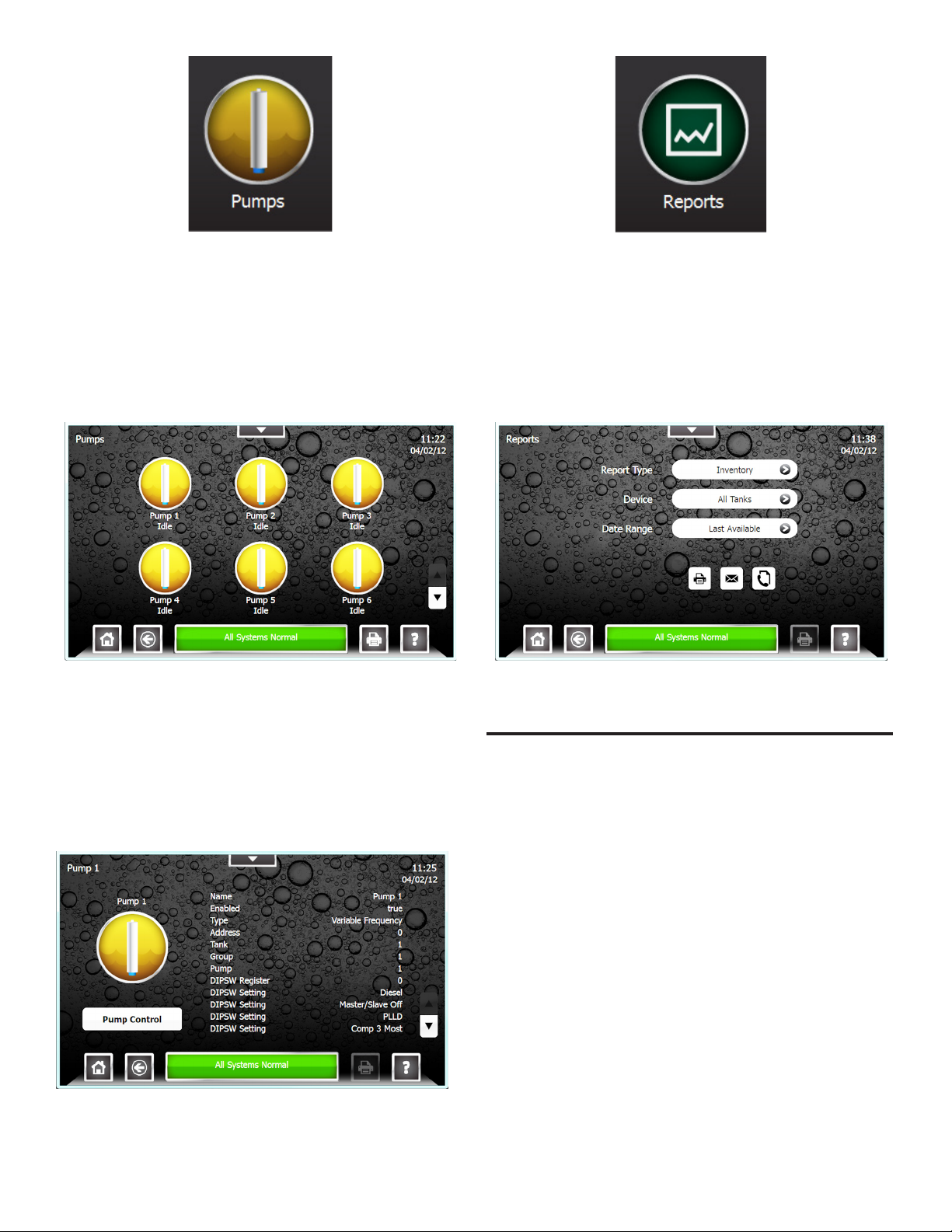
Pump Status Summary Screen
This screen displays a graphical representation of the
submersible pumps, the name of the pump, and an
indication whether the pump is running or not. An alarm
condition on the pump is also indicated here, if present.
Pressing the print button while on this screen will print a
Pump Status Report for all Pumps.
Report Generator Screen
The Report Generator screen is used to create a variety of
reports. The report options available depend on software
options and system conguration. The available reports
include: Alarm History, Application Event History, Setup,
Inventory, Delivery, Tank Test, SCALD, Line Test, Pump
Status, Reconciliation, Regulatory, and Sensor Status.
To access the Pump Status Summary screen select
Pumps from the Quick Jump Menu (QJM).
Pump Status Detail Screen
This screen provides a variety of information regarding the
pump and it settings. Information including: Pump Name,
Enabled/Disabled, Controller Type, Controller Address, the
tank the pump is installed in, and Pump Group. The screen
also includes status information such as Pump Running, has
the pump been forced off, and if a hook signal is present.
Pressing the print button while on the page will print a Pump
Status Report for just this tank.
To access the Report Generator screen select Reports
from the Quick Jump Menu (QJM).
Pump Controls feature can be accessed using the Control
Button on the Pump Status Detail Screen. This will allow
authorized users and technicians to reset the Pump
hardware and software.
10
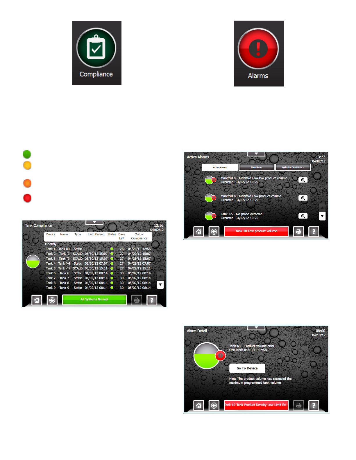
Compliance Screen
The Compliance screen displays regulatory status
information for Tanks, Manifolds, Lines, and Sensors.
Each page lists every device, the number of days
remaining and the date when that specic device will be
out of compliance. The screen will indicate compliance
concerns with a color coded status indicator.
Compliance Status
Compliant – The device is in compliance.
Compliance Alert – The device will be out of
compliance in 8 to 14 days.
Compliance Warning – The device will be out of
compliance in 1 to 7 days.
Compliance Alarm – The device is out of
compliance.
Tank Compliance Screen
Alarm Summary Screen
The Alarm Summary screen displays active alarms, an
alarm history, and an application event history. From the
alarm summary screen users can view currently active
alarms and review alarm and application event histories,
as well as access more details about active alarms.
To access the Alarm Summary screen select Alarms from
the Quick Jump Menu (QJM).
Active Alarm Detail Screen
The Active Alarm Detail screen provides detailed
information regarding an active alarm. These details
include the device, the date and time the alarm occurred,
and a description of the alarm. It will also provide hints for
recommended actions and precautions. Many alarms will
also have a “Go To Device” link which directs users straight
to the device to allow users to perform corrective actions.
Pressing help from this screen will provide further details
regarding the specic alarm. To access the Alarm Detail
Screen select an Alarm from the list of active alarms.
11
 Loading...