


TS-550

Secondary Containment Monitoring
Installation & User’s Guide
TS-550/TS-5000 consoles
Franklin Fueling Systems • 3760 Marsh Rd. • Madison, WI 53718 USA
Tel: +1 608 838 8786 • 800 225 9787 • Fax: +1 608 838 6433 • www.franklinfueling.com

Notice
Franklin Fueling Systems (FFS) strives to produce the nest manual possible and to ensure that the information that
it contains is complete and accurate. However, FFS reserves the rights to change this document and specications at
any time without notice. FFS makes no expressed or implied warranty with regard to the contents of this manual. FFS
assumes no liability for errors, omissions or for any damages, direct or consequential, that may result from the use of this
document or the equipment that it describes.
This manual is for use expressly with the TS-550, TS-5000, and TS-SCM at their approved specications.
For further information and installation and programming instructions, please refer to the T5 Series Installation Guide (p/n
000-2150) and/or T5 Series Programming Guide (p/n 000-2142).
Trademarks
INCON®, Tank Sentinel®, System Sentinel®, System Sentinel AnyWare® and Tank Sentinel AnyWare® are registered
trademarks of Intelligent Controls. All brand and product names are trademarks or registered trademarks of their
respective companies.
Inspection of Materials
Visually inspect all components for defects or damage prior to installation. If any defect or damage is found, do not use the
product and contact Franklin Fueling Systems for further assistance.
Warranty Information
Please refer to the FFS Fuel Management Systems & Product Warranty Policy for all warranty information.
Contacting Franklin Fueling Systems (FFS)
Please feel free to contact us by mail at:
Franklin Fueling Systems
3760 Marsh Rd.
Madison, WI 53718 USA
Or contact us by phone, fax or e-mail:
Tel: +1 800 225 9787 E-mail: sales@franklinfueling.com
Fax: +1 608 838 6433 techserve@franklinfueling.com
Ofce and Sales Hours: 8 a.m. to 5 p.m. CST - Monday through Friday
Technical Support Hours: 7 a.m. to 7 p.m. CST - Monday through Friday
Please visit our website at www.franklinfueling.com
Copyright ©2007 by Franklin Fueling Systems (FFS). No part of this publication may be reproduced in any form without the prior written consent of FFS.
ii
All rights reserved.

Contents
Notice..................................................................................................................................ii
Important Safety Messages .............................................................................................. 1
Overview.............................................................................................................................2
Applications ..............................................................................................................................2
Site Requirements .................................................................................................................... 3
Available Congurations .................................................................................................................. 3
Installation ..........................................................................................................................4
SCM Setup (Console Programming) ................................................................................7
AC Input Module .......................................................................................................................7
4-20mA Input Module ................................................................................................................8
Relay Module ............................................................................................................................ 8
Turbine Pump Interface (TPI) Applications (Alternate STP Control) ......................................... 10
Secondary Containment Monitoring Application ....................................................................... 11
SCM Status and Control Screens ....................................................................................12
SCM Status Summary Screen .................................................................................................. 12
SCM Control Screen ................................................................................................................. 13
Status Indicator Table ...................................................................................................................... 13
Control Indicator Table .................................................................................................................... 13
Learn Indicator Table ....................................................................................................................... 13
Pre-Operational Containment Testing ............................................................................. 14
Required Equipment .................................................................................................................14
Containment Tightness and Continuity Test .............................................................................. 14
STP Siphon Flow Rate Test ...................................................................................................... 16
Learn Process .................................................................................................................... 17
When to Learn/Re-Learn .......................................................................................................... 17
Procedure ................................................................................................................................. 17
Learn Messages ....................................................................................................................... 18
SCM Reports ...................................................................................................................... 19
SCM Alarm Reports .................................................................................................................. 19
Application Event Reports ........................................................................................................19
Alarms ................................................................................................................................20
SCM Alarms and Warnings ....................................................................................................... 20
Clearing Alarms ........................................................................................................................21
Enabling/Disabling SCM ...................................................................................................22
Enabling SCM Channels ........................................................................................................... 22
Disabling SCM Channels .......................................................................................................... 22
SCM Annual Functional Testing ....................................................................................... 23
iii
Important Safety Messages
INCON equipment is designed to be installed in association with volatile hydrocarbon liquids such as gasoline and diesel
fuel. Installing or working on this equipment means working in an environment in which these highly ammable liquids
may be present. Working in such a hazardous environment presents a risk of severe injury or death if these instructions
and standard industry practices are not followed. Read and follow all instructions thoroughly before installing or working
on this, or any other related, equipment.
As you read this guide, please be aware of the following symbols and their meanings:
Warning
Caution
Danger
Warning
Warning
This symbol identies a warning. A warning sign will appear in the text of this document when a potentially
hazardous situation may arise if the instructions that follow are not adhered to closely. A potentially hazardous
situation may involve the possibility of severe bodily harm or even death.
This is a caution symbol. A caution sign will appear in the text of this document when a potentially hazardous
environmental situation may arise if the instructions that follow are not adhered to closely. A potentially
hazardous environmental situation may involve the leakage of fuel from equipment that could severely harm
the environment.
This symbol identies an electrical danger. An electrical danger sign will appear in the text of this document
when a potentially hazardous situation involving large amounts of electricity may arise if the instructions that
follow are not adhered to closely. A potentially hazardous situation may involve the possibility of electrocution,
severe bodily harm, or even death.
Follow all applicable codes governing the installation and servicing of this product and the
entire system. Always lock out and tag electrical circuit breakers while installing or servicing
this equipment and any related equipment. A potentially lethal electrical shock hazard and the
possibility of an explosion or re from a spark can result if the electrical circuit breakers are
accidentally turned on during installation or servicing. Please refer to the Installation and Owner’s
Manual for this equipment, and the appropriate documentation for any other related equipment, for
complete installation and safety information.
Follow all federal, state and local laws governing the installation of this product and its associated
systems. When no other regulations apply, follow NFPA codes 30, 30A and 70 from the National Fire
Protection Association. Failure to follow these codes could result in severe injury, death, serious
property damage and/or environmental contamination.
Warning
Warning
Warning
Warning
Warning
Warning
Always secure the work area from moving vehicles. The equipment in this manual is usually
mounted underground, so reduced visibility puts service personnel working on this equipment in
danger from moving vehicles entering the work area. To help eliminate these unsafe conditions,
secure the area by using a service truck to block access to the work environment, or by using any
other reasonable means available to ensure the safety of service personnel.
When the Tank Sentinel system is used to monitor tanks containing gasoline or other ammable
substances, you may create an explosion hazard if you do not follow the requirements in this
manual carefully.
All wiring must enter the console’s enclosure through the designated knockouts. An explosion
hazard may result if other openings are used.
All wiring from probes or sensors to the Tank Sentinel console must be run in conduit separate
from all other wiring. Failure to do so will create an explosion hazard.
Substituting components could impair intrinsic safety. T5 series consoles are intrinsically safe
for sensors installed in – Class I, Division 1, Group D – hazardous locations. Substitution of
components could make the energy limiting circuitry in the system ineffective and could cause
an explosion hazard. Repairs to a T5 series console or attached components should only be
performed by a qualied, factory-trained technician.
TS-SCCM contains aluminum, care must be taken to avoid ignition due to impact.
1
Overview
The TS-SCM (Secondary Containment Monitoring) system is a continuous secondary containment monitoring system that
monitors the interstitial spaces of double walled tanks and sumps, secondarily contained product and vapor return piping.
This product can be ordered as an available option with Franklin Fueling Systems’s TS-550 and TS-5000 FMS consoles.
The TS-SCM system is comprised of an application running on a T5 series FMS console and all necessary input and
output modules with installation kits. The Secondary Containment Control Module (SCCM) consists of a vacuum sensor,
solenoid valve, mechanical bypass valve, and vacuum manifold. SCM uses the STP siphon port vacuum to evacuate the
containment space and AutoLearn® technology to determine the characteristics of each secondary containment area that
is monitored.
Warning
SCM equipment operates at a standard 2" to 6" Hg and should only be used to monitor containments that are designed to withstand these vacuum levels. Refer to the containment manufacturer
for further information.
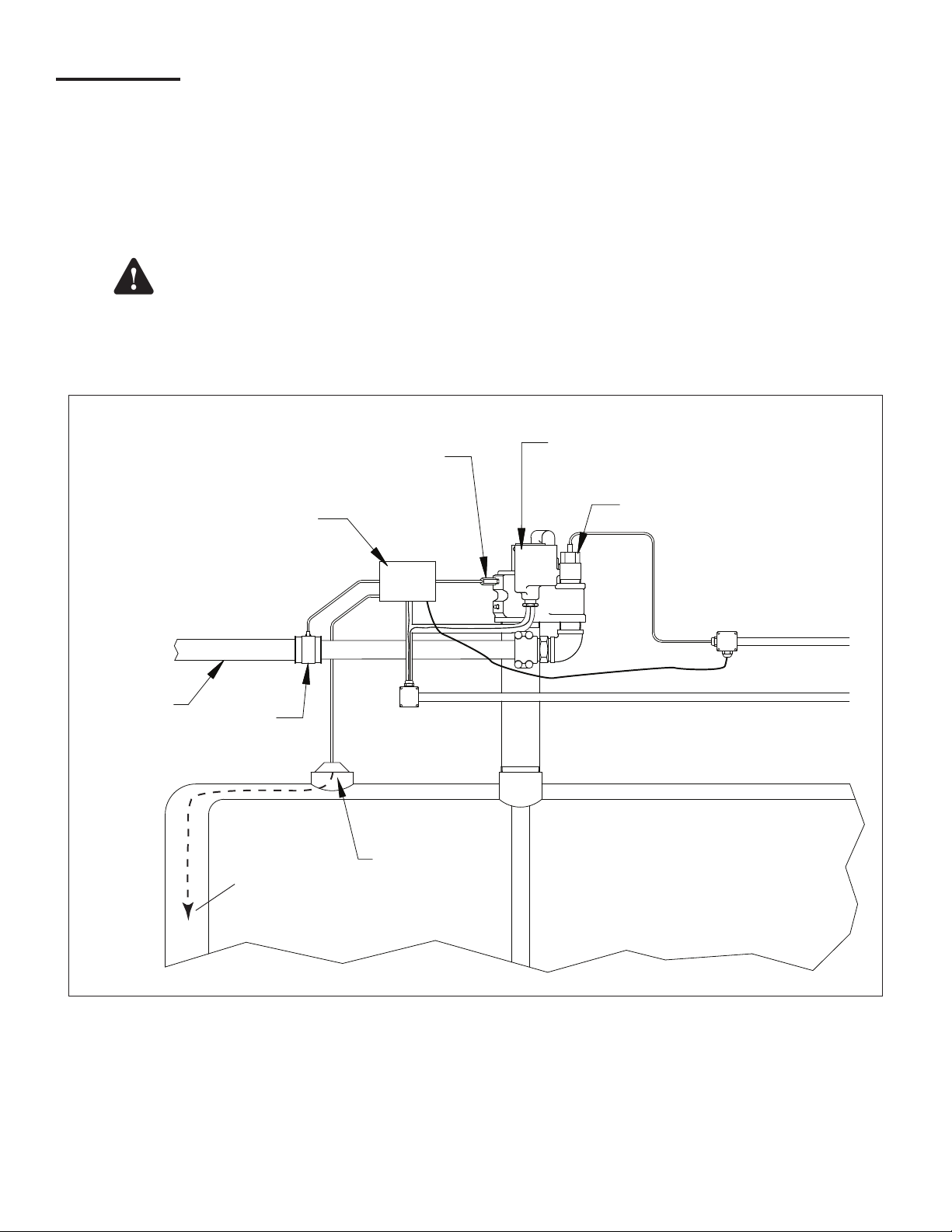
Applications
The following diagram illustrates a typical installation of SCM equipment inside of a STP sump.
FE Petro
Submersible
Pump
TS-LSU500
High Voltage Conduit
APT
Double Wall
Product Pipe
Syphon
Check Valve
Integral Solenoid
Vacuum Sensor
TS-SCCM/1
APT
Test
Boot
Intrinsically
Safe Conduit
To Bottom
of Tank
Tank
Containment
Install Kit
Figure 1 – TS-SCM System Overview
2
Site Requirements
Total Containment Volume*
Normal Operating Vacuum 2" – 6" Hg (1 – 3 PSIG)
Pre-Programmed Maximum
Shutdown (Alarm Condition)
Mechanical Relief Valve
Vacuum**
Jumper Tubing Use only supplied vacuum tubing
Vacuum Sensor Wiring
Solenoid Wiring
Minimum - 0.25 gallons (1 L)
Maximum - 500 gallons (1879 L)
9" Hg (4.5 PSIG)
10" Hg (5 PSIG)
Belden No. 87761(0.12" OD) to 400 ft.
Belden No. 89182(0.31" OD) to 500 ft. (maximum distance)
600 V, 18 AWG minimum, UL approved
refer to ANSI/NFPA70 or CEC electrical codes
*Refer to manufacturers’ installation
guides or data sheets to calculate
containment area volumes.
**All containment areas MUST be
compatible with the vacuum levels
listed.
Note: SCM should be tested annually after installation.
The term containment (in secondary containment) refers to the interstitial spaces of double walled piping, sumps and
tanks that serve as a secondary containment if the primary containment is damaged.
Individual containment sections of a given product pipeline may be jumpered together via a vacuum line to form one larger
single containment. An example of ‘jumpered’ containment spaces is the secondary containment layer of product piping
from the turbine containment to the rst dispenser, and then jumpered to the secondary containment layer of the same
product piping on the other side leading to the next dispenser containment area.
Several containment areas may be grouped together and used with a single Secondary Containment Control Module (TSSCCM). No more than four (4) SCM groups should be used per pump siphon. The combination of any containment group
may not exceed the volume limits listed for SCM.
Note: DO NOT jumper tank interstitials with other tank interstitials or other containments.
Note: DO NOT jumper containment areas of unlike product pipelines together.
Note: If grouping multiple containment areas together, the installer will need to purchase and use the vacuum hose,
ttings, and clamps to secure the connection as specied by FFS.
Note: Both intrinsically safe and explosion proof conduits need to be available inside of the turbine containment for the
TS-SCCM.
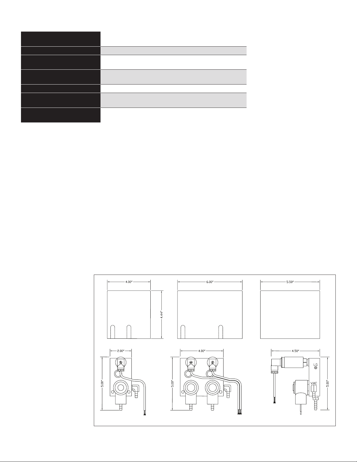
Available Congurations
Refer to Franklin Fueling
Systems’s current Fuel
Management Systems
Product Catalog for
a complete listing
of the current SCM
congurations offered.
Note: The SCCM 1 (as
pictured in Figure
2) can monitor one
containment group
and the SCCM
2 can monitor
two containment
groups.
TS-SCCM/1 TS-SCCM/2 TS-SCCM Side View
Figure 2 – SCCM 1 and SCCM 2 Dimensions
3
Installation
Before starting installation, conduct a site survey to identify potential containment groups. Based on that survey, plan out
which STP sump the equipment will be installed in and how containment areas will be grouped together.
Warning
Lockout and tag circuit breakers, and disconnect console power wiring before installing or servicing
any system wiring.
Warning
Warning
Caution
DO NOT make solenoid and/or sensor wiring connections with live power connected to the console
or any module.
TS-SCCM contains aluminum, care must be taken to avoid ignition due to impact.
Do not run intrinsically safe (IS) wiring and non-intrinsically safe (non-IS) wiring in the same
conduit.
Note: TS-SCCM must be installed in accordance with the national electrical code, ANSI/NFPA 70, CEC or other
applicable national or local codes.
Note: Maximum torque on supplied hose clamps is 20 inch-lbs.
1. Pull all wiring through the conduits that will be used for the TS-SCCM vacuum sensor and solenoid valve. The
intrinsically safe (IS) sensor wiring must be run in an IS conduit. The non-IS solenoid wiring must be run in an
approved explosion proof rigid metal conduit.
2. Mount the TS-SCCM inside of the turbine
containment area, supported by rigid,
explosion proof conduit. Then orientate the
units to allow enough clearance to make the
vacuum line connections without stretching,
kinking, or creating sharp bends in vacuum
hoses. The SCCM cover is installed with the
label upwards. See Figure 3.
3.
Connect the solenoid wiring to the eld wiring
using wire nuts to secure the connections.
Replace the explosion proof junction box cover.
4. Connect the vacuum sensor wiring to the IS
eld wiring using epoxy wire seals to secure
the connections. Replace the IS junction box
cover.
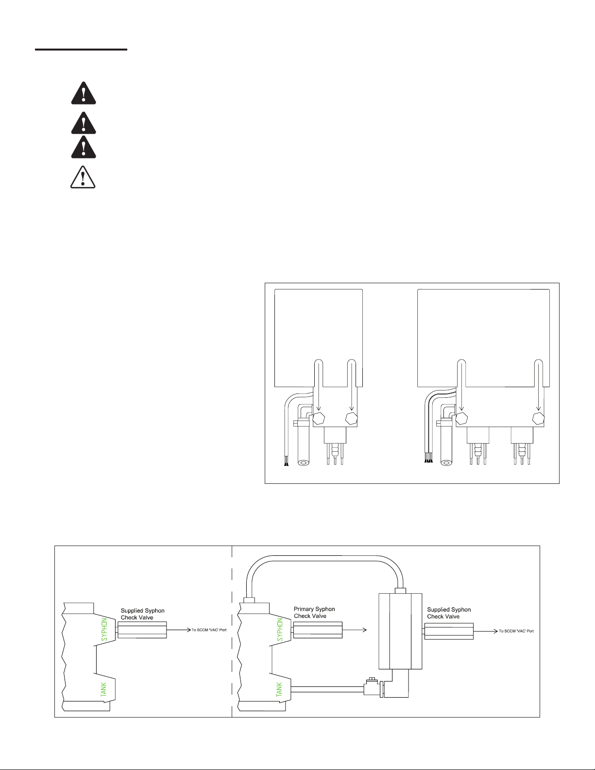
5. Install the supplied Siphon Check Valve with
the inscribed Flow Arrow pointing to the STP.
Apply a non-hardening, thread sealing
TS-SCCM/1 TS-SCCM/2
Figure 3 – Cover Installation (rear view)
compound to the threads, then thread the valve body into the submersible turbine’s siphon port. If necessary, use a
FFS Secondary Syphon Assembly to connect the SCCM to the syphon port of the STP.
Single Syphon (typical)
Secondary Syphon
Assembly
STPSTP
Secondary Syphon Kit
Figure 4 – Secondary Syphon Assembly Installation
4
6. Plumb the siphon hose from the VAC port of the TS-SCCM to the siphon check valve. Secure the hose to the ttings
Earth Ground
using one of the supplied hose clamps at each end.
7. Plumb the containment vacuum hose from the INT port of the TS-SCCM to the containment area to be monitored.
Secure the hose to the tting using one of the supplied hose clamps per tting. Install T-ttings and clamps where
necessary to connect the hoses if more than one containment area will be monitored as a group.
Note: The containment vacuum hose must be placed in the lowest point of the containment space. For double walled
tanks, this means ensuring that the vacuum line rests at the bottom most part of the tanks interstitial space. Use
the same industry procedures used to install any sensor at the bottom of a double walled tank.
8. Secure all containment boots, lids and caps. Clean pipe surfaces to clear debris or foreign objects prior to tightening
secondary test boots on secondary containment product or vapor return piping. Make all jumper connections inside of
dispenser sumps by using supplied hardware.
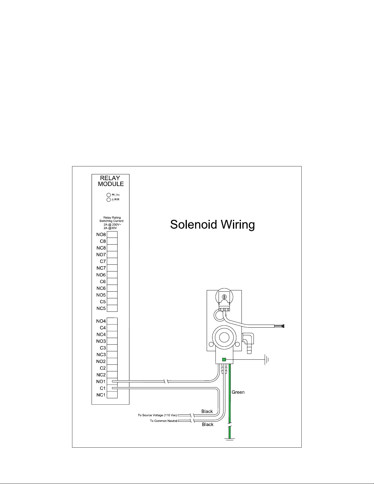
9. Inside the console, the TS-SCCM solenoid wiring must enter the console from the explosion proof rigid conduit through
a designated knockout on the non-IS side of the barrier inside. Connect the line, neutral, and ground wire of the
solenoid to a single unused channel on the Relay Module (RLY). The solenoid should be wired to the Common (C) and
Normally Open (NO) contacts of the channel selected. Source voltage (110 VAC) will need to be provided to the dry
contact relay.
Figure 5 – Solenoid Wiring
5
Warning
console is positively shut down during installation and service. Failure to remove power may result
in damage to equipment, personal injury or even death.
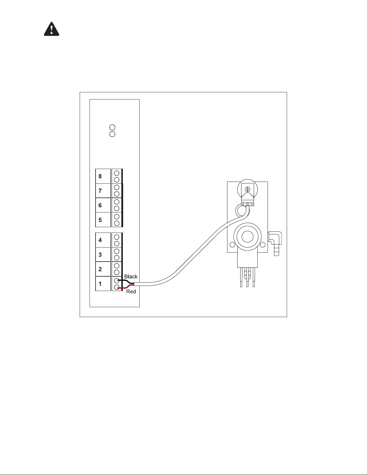
10. The TS-SCCM sensor wiring must enter the console in IS conduit through a knockout on the IS side of the barrier.
Secure each pair of sensor wires to a single channel on the 4-20mA Analog Input Module. Always use the next
available channel when wiring; for example, if Channels 1 – 3 are being used, Channel 4 must be used next. Pay
close attention to the polarity (+/-) of the wires.
4-20mA Input
Module
RUN
ERR
–
+
–
+
–
+
–
+
If using console power wires to provide power to a dry contact relay channel, ensure that the
–
+
–
+
–
+
–
+
Figure 6 – Vacuum Sensor Wiring
6
 Loading...