


TS-DTU

Data Transfer Unit
Dispenser Retrofi t Manual
Model TS-DTU
Franklin Fueling Systems • 3760 Marsh Rd. • Madison, WI 53718 USA
Tel: +1 608 838 8786 • 800 225 9787 • Fax: +1 608 838 6433 • www.franklinfueling.com

2
Important Safety Messages
Franklin Fueling Systems (FFS)/Healy equipment is designed to be installed in association with volatile hydrocarbon
liquids such as gasoline and diesel fuel. Installing or working on this equipment means working in an environment in which
these highly fl ammable liquids may be present. Working in such a hazardous environment presents a risk of severe injury
or death if these instructions and standard industry practices are not followed. Read and follow all instructions thoroughly
before installing or working on this, or any other related, equipment.
As you read this guide, please be aware of the following symbols and their meanings:
This symbol identifi es a warning. A warning sign will appear in the text of this document when a potentially
hazardous situation may arise if the instructions that follow are not adhered to closely . A potentially hazardous
situation may involve the possibility of severe bodily harm or even death.
This is a caution symbol. A caution sign will appear in the text of this document when a potentially hazardous
environmental situation may arise if the instructions that follow are not adhered to closely. A potentially
hazardous environmental situation may involve the leakage of fuel from equipment that could severely harm
the environment.
Warning
Caution
Follow all applicable codes governing the installation and servicing of this product and the
entire system. Always lock out and tag electrical circuit breakers while installing or servicing
this equipment and any related equipment. A potentially lethal electrical shock hazard and the
possibility of an explosion or fi re from a spark can result if the electrical circuit breakers are
accidentally turned on during installation or servicing. Please refer to the Installation and Owner’s
Manual for this equipment, and the appropriate documentation for any other related equipment, for
complete installation and safety information.
Follow all federal, state and local laws governing the installation of this product and its associated
systems. When no other regulations apply, follow NFPA codes 30A and 70 from the National Fire
Protection Association. Failure to follow these codes could result in severe injury, death, serious
property damage and/or environmental contamination.
Always secure the work area from moving vehicles. The equipment in this manual is usually
mounted underground, so reduced visibility puts service personnel working on this equipment in
danger from moving vehicles entering the work area. To help eliminate these unsafe conditions,
secure the area by using a service truck to block access to the work environment, or by using any
other reasonable means available to ensure the safety of service personnel.
Use circuit breakers for multiple disconnect to turn off power and prevent feedback from other
dispensers.
Warning
Warning
Warning
Warning
Important: All electrical and hydraulic plumbing fi ttings referred to in these instructions must be UL “listed” or
“recognized” for the purpose.
Important: The TS-DTU will increase the current draw of the dispenser by 0.25 amps. Use the label supplied to note this
change.

3
Contents
Important Safety Messages ............................................................................................2
Purpose: .................................................................................................................................4
Specifi cations: .........................................................................................................................5
Tools Required .......................................................................................................................6
Installing the TS-DTU in the Dispenser .........................................................................6
Mounting the TS-DTU module ........................................................................................6
Intrinsically Safe Wiring ..................................................................................................6
Connecting the Vapor Flow Meter and Vapor Pressure Sensor..................................7
TS-VFM Splice ..............................................................................................................................7
TS-VPS Splice ...............................................................................................................................7
Dispenser Specifi c Installation ......................................................................................7
Gilbarco Advantage Narrow Frame ........................................................................................8
Gilbarco Encore 300 and 500 Series ....................................................................................12
Tokheim Premier B ...............................................................................................................16
Tokheim Premier C ...............................................................................................................20
Wayne Vista 1 .......................................................................................................................28
Wayne Vista 2 .......................................................................................................................32
Wayne Vista 3 .......................................................................................................................36

4 General Information
Purpose:
This procedure describes the tools, methods and skill levels required to install an INCON/Franklin Fueling Systems model
TS-DTU, Data Transfer Unit in UL Approved Dispensers. Each installation of a TS-DTU in a dispenser requires that a TS-
DRK, dispenser installation kit, be used. The TS-DRK is ordered by specifi c dispenser types. Please refer to the Table
1 for the correct TS-DRK model. Only INCON/Franklin Fueling Systems trained and certifi ed contractors will be able to
perform these retrofi ts or warranty will be void. The installer shall be a skilled petroleum technician and thoroughly familiar
with the requirements of State, Federal and local codes for installation and repair of gasoline dispensing equipment. Also,
they shall be aware of all the necessary safety precautions and site safety requirements to assure a safe and trouble free
installation. NOTE: All electrical fi ttings referred to in these instructions must be UL “listed” or “recognized” for the purpose.
Important Safety Messages
Before installing the equipment, read, understand and follow:
- The National Electrical Code (NFPA 70)
- The Automotive and Marine Service Code (NFPA 30A)
- Any national, state and local codes that may apply.
The failure to install the equipment in accordance with NFPA 30A and 70 may adversely affect the safe use and operation
of the system. Accurate, sound installations reduce service calls: Use experienced, licensed contractors that practice
accurate, safe installation techniques. Careful installation provides a sound troubleshooting framework for fi eld repairs and
can eliminate potential problems.
1. Read all instructions before beginning.
2. Follow all safety precautions:
• Barricade the area.
• Do not allow vehicles or unauthorized people in the area.
• Do not smoke or allow open fl ames in the area.
• Do not use power tools in the work area.
• Wear eye protection during installation.
3. Use circuit breaker for multiple disconnects to turn off power and prevent feedback from other dispensers.
5General Information
Specifi cations:
Power 100-240 VAC, 60 Hz, 0.25 A
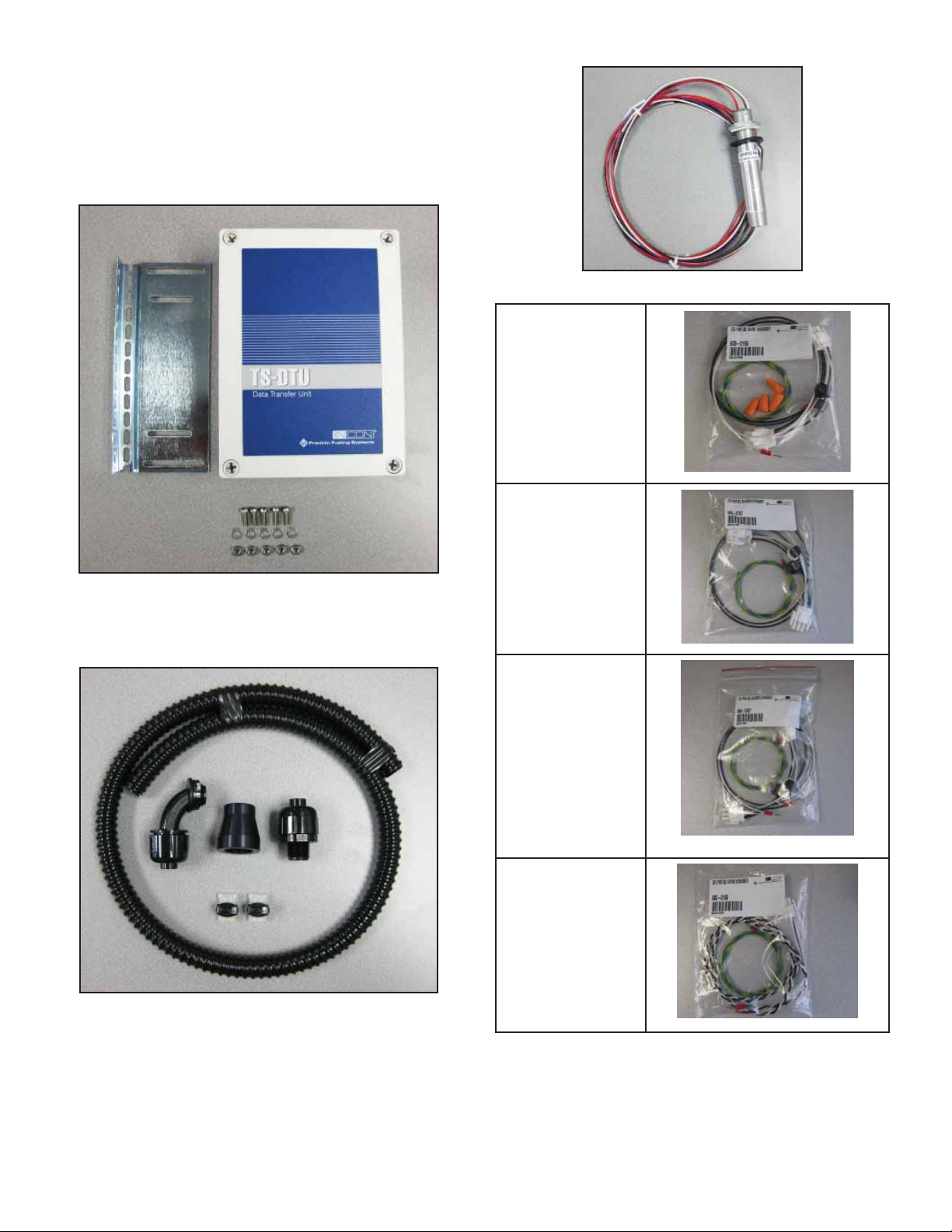
Parts List
The TS-DTU and TS-DRK installation kit consists of the
following major components. Make sure you have these
parts before installing the DTU.
Figure 1: TS-DTU / P Data Transfer Unit
• TS-DTU
• Mounting Plate
• Fasteners (5 screws, nuts, and washers)
Figure 2: 020-1513 IS Conduit Kit
• Straight Conduit Fitting
• 90degree Conduit Fitting
• Conduit Reducer
• Flexible Conduit (1/2”PVC)
• Two splice connectors
Figure 3: 131610 Potted Nipple Assembly
Wayne Dispenser
Power Harness
600-0166
Gilbarco Encore
Dispenser Power
Harness 600-0167
Gilbarco Advantage
Dispenser Power
Harness 600-0168
Tokheim Dispenser
Power Harness
600-0165
Figure 4: Power Harness Kits
6 General Information
General Instructions
Tools Required
(This applies to all dispenser installation procedures)
Assorted Open End Wrenches 1/4” through 3/4”
Wire Cutters/Strippers 16 AWG to 26 AWG
3/8” Drill Assembly
Assorted Drill Bits 1/16” through 7/16”
Assorted Screwdrivers (Flat blade-one must be 1/8” wide)
3/4" Conduit Hole Punch (For potted nipple assembly)
Electrical Multi-meter
12” adjustable Wrench
18” Channel lock Pliers
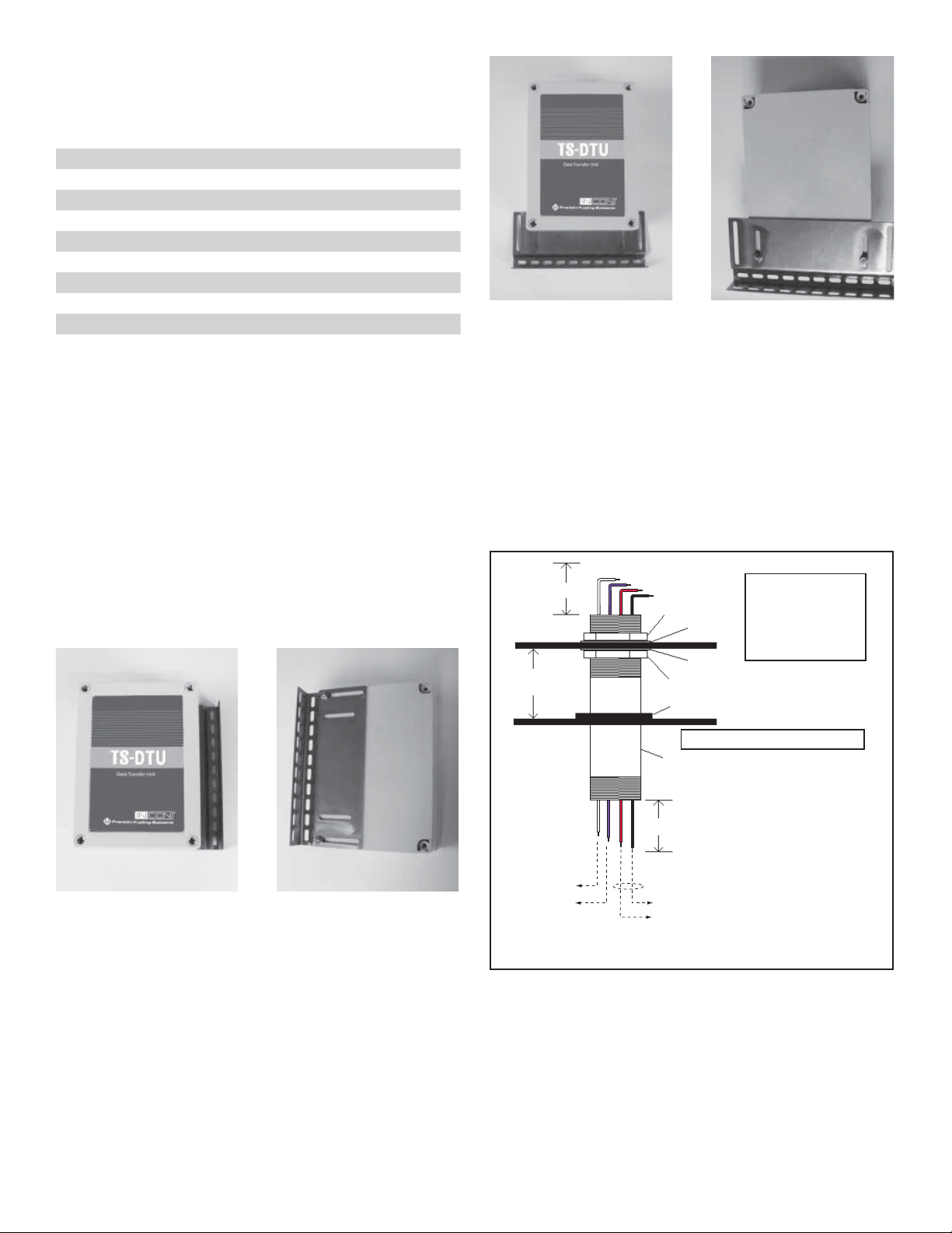
Attaching the Mounting Bracket
For each dispenser installation, the mounting bracket will
need to be attached to the back side of the TS-DTU. Refer
to each dispenser installation instruction as it will specify
the correct orientation of the bracket
1. Remove the TS-DTU enclosure cover and set it
aside.
2. Find the correct orientation for the mounting
bracket in the dispenser-specifi c instructions.
3. Find two screws, washers, and star nuts from the
TS-DTU/P kit. Insert the two screws into the two
mounting holes of the front face of the TS-DTU
enclosure.
4. Put the mounting bracket on the side of the DTU
enclosure and install a washer and star nut.
Figure 5: Mounting Bracket On Side Of Unit
Figure 6: Mounting Bracket On Bottom Of Unit
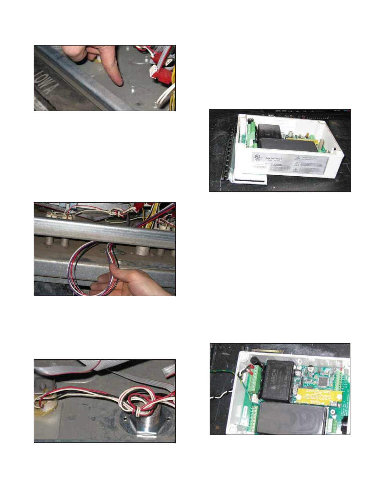
Intrinsically Safe Wiring
The Intrinsically safe wiring is the same for all type of
dispensers. The wires from the top end of a potted nipple
should be connected to the TS-DTU module and from the
bottom end to the TS-VFM and TS-VPS. These wires
connect intrinsically safe devices (TS-VFM and TS-VPS) to
the associated apparatus (TS-DTU) and therefore must be
protected in non-hazardous area where TS-DTU is
located.
List of Items Included with Assembly
1. Hex jam nut (2 required)
2. Metal washer (2 required)
3. Rubber washer (1 required if
dispenser has two decks between
hydraulic & electronic areas)
4. 3/4" x 6" potted conduit
(36" of wires at module end,
42" of wires vapor signals)
42"
Some dispensers have two decks
between hydraulics and electronics
Free space
between decks
36"
Wires from
potted conduit to
sensors
1
1
2
3
4
2
VFM
VPS
Shielded cable
To TS-DTU
Wire Color Codes
Red......... VFM+
Black....... VFM–
Purple ..... VPS +
White ...... VPS–
Figure 7: Potted Nipple Assembly
Follow the dispenser-specifi c instructions for the
installation location and procedure of the potted nipple on
the dispenser vapor barrier.
7General Information
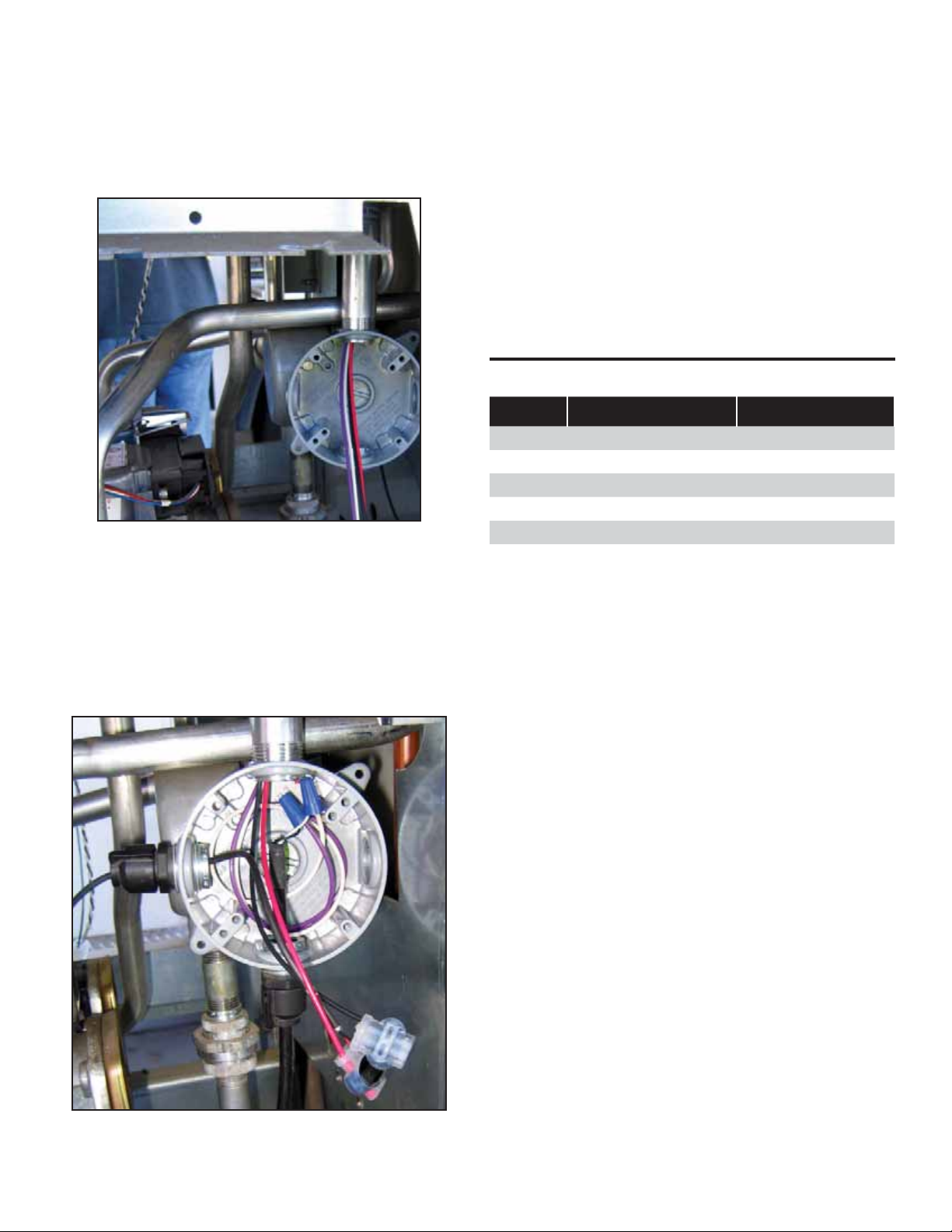
Connecting the Vapor Flow Meter and Vapor
Pressure Sensor
The connection of potted nipple to the TS-VFM and TS-
VPS in the lower section of the dispenser is the same for all
dispensers. For ease of installation, a junction box may be
connected directly to the bottom of the potted nipple. Note,
the potted nipple is a ¾” conduit thread, see Figure 8.
Figure 8: Junction Box Connected to Potted Nipple
TS-VFM Splice
1. Find two-splice connectors in the IS Wiring Kit, 020-
1513.
2. Make the following splice connections:
• Red wire of potted nipped to Red wire of TS-VFM
cable.
• Black wire of potted nipple to Black wire of TS-VFM
cable.
Figure 9: VFM and VPS Spices
TS-VPS Splice
1. Find two wire nuts in the Power Harness Kit, 600-
016X.
2. Make the following splice connections:
• Purple wire of potted nipped to Black wire of TS-
VPS cable.
• White wire of potted nipple to White wire of TS-VPS
cable (Refer to Figure 9).
Dispenser Specifi c Installation
This manual covers the following types of dispensers:
Make Type Installation Kit
Gilbarco Advantage TS-DRK/A
Encore 300 & 500 TS-DRK/E
Tokheim Premier B TS-DRK/T
Tokheim Premier C TS-DRK/T
Wayne Ovation TS-DRK/W
Vista 1V, 2V, 3V TS-DRK/W
Table 1: Dispenser Kits
8
Gilbarco Advantage Narrow Frame - DTU Installation
Gilbarco Advantage Narrow Frame
This section illustrates the basic components needed
to retrofi t a TS-DTU module into an existing or UL
remanufactured dispenser. This system can be installed
in any “Non-Vapor or Vapor Ready” dispenser including
dispensers with existing “Balance” or “VacAssist” piping.
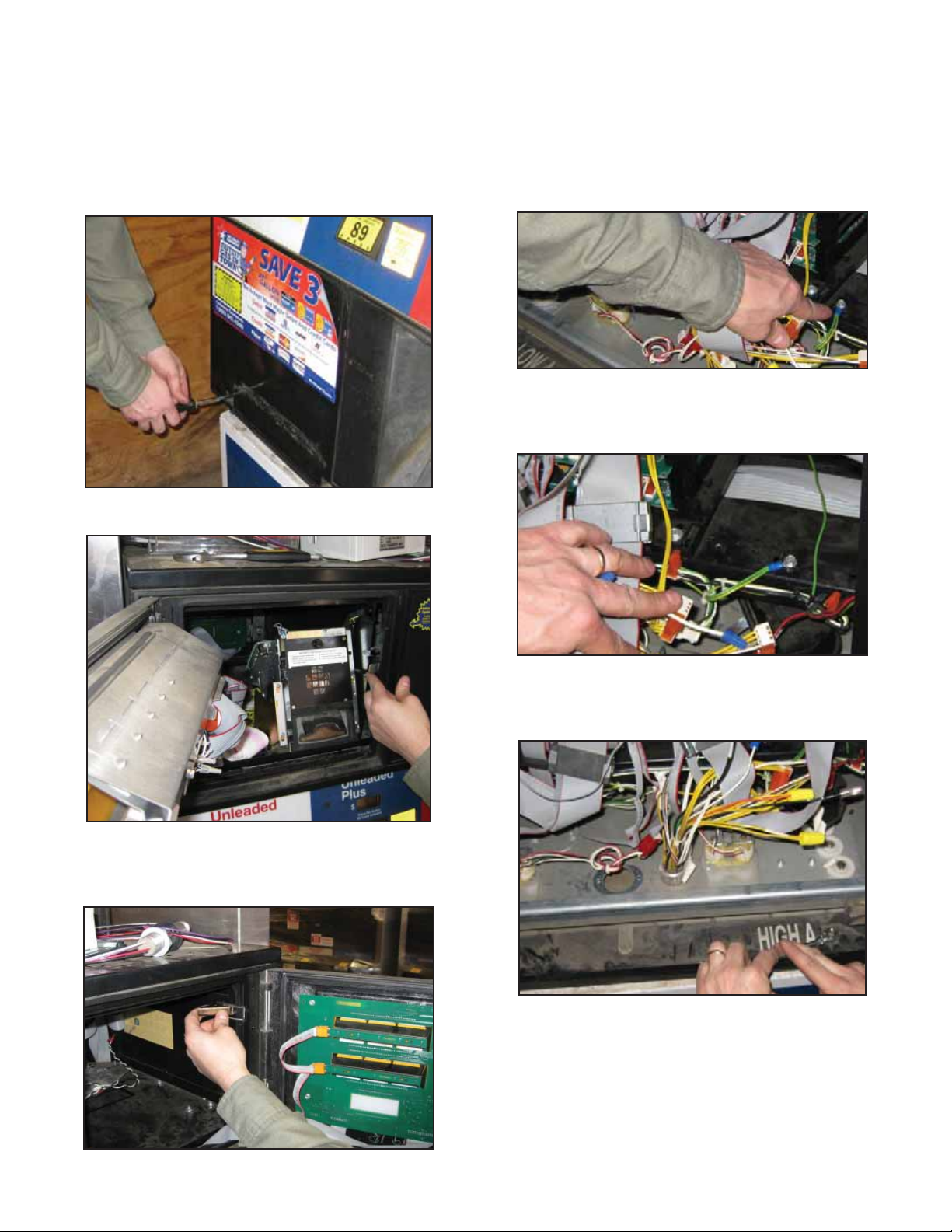
1. Loosen three bolts at the bottom of each main
door assembly.
Figure 1: Loosen Bolts
2. Unlock the left options door on each main door.
Figure 2: Open Options Door
3. Lift latch on right side of left options door opening
to release right options door on each side of the
dispenser.
Figure 3: Release Options Door
4. Disengage two latches, one in each right and left
options door openings, and open main door on
both sides of dispenser.
5. Move to side A of dispenser. Side A can be
determined by the side that the credit card reader
(crind) tray pops out.
6. Find ground wire mounting location shown and
remove screw and star washer.
Figure 4: Find Ground Wire
7. Reinstall ground with ring terminal screw and star
washer in alternate location shown. Tighten screw
securely.
Figure 5: Reinstalled Ground Wire
8. Find shield covering opening in air gap and
remove two bolts from shield. Retain shield and
bolts for future reassembly.
Figure 6: Air Gap Shield
9
Gilbarco Advantage Narrow Frame - DTU Installation
9. Remove two screws from upper air gap knock-out
cover and remove. Discard cover but keep screws
for reuse.
Figure 7: Remove Screws
10. Remove two screws from lower air gap knockout
cover and remove. Discard cover and screws.
11. Remove lower door from side A of dispenser using
key lock on right side of door. Save door for future
reassembly
12. Find potted nipple assembly, 131610. Remove all
washers and nuts and set aside.
13. Pull wires from top side of potted nipple assembly
through dispenser hydraulics enclosure up through
opening in lower air gap knock-out.
Figure 8: Potted Conduit wires
14. Attach one nut and washer onto the potted nipple
assembly before pushing wires up through electrical
enclosure.
15. Pull wires and then nipple assembly up into electronics
enclosure. Fit washer and nut over wires and tighten
nut securely in place, as shown in Figure 9.
Figure 9: Potted Nipple Installed
16. Reattach air gap shield using screws previously
retained in step 8.
17. Reinstall the screws previously retain in step 9.
These screws seal the holes left behind by the air
gap knockout.
18. Find TS-DTU / P kit and remove brackets, DTU,
and hardware from box.
19. Remove cover from DTU.
20. Install mounting bracket to DTU with two screws,
nuts and washers from hardware provided with
DTU as described in the General Information
section. Ensure that bracket is installed on correct
side as shown.
Figure 10: Mounting Bracket on DTU
21. Remove two screws from IS wiring cover inside
the DTU and remove cover. Retain cover and
screws for reassembly
22. Find the 90 degree fi tting from IS wiring kit,
020-1513. Remove nut from 90 degree fi tting.
Attach fi tting to opening nearest IS wiring terminal
block of DTU using nut previously removed.
23. Find power harness kit part number 600-0168.
Find the Gilbarco Advantage power harness and
ground with ring terminal as shown in fi gure 4 of
the Parts List.
24. Put wiring harness end with crimp connector
through opening in DTU nearest terminal block
J1. Attach white lead to terminal block position
labeled NEUTRAL and black lead to terminal
block position labeled L1 on terminal block J1 of
DTU. Attach ground wire to terminal block position
labeled GND of J2 on DTU.
Figure 11: DTU Power Connections
25. Move DTU assembly to dispenser nearest
intended mounting location
10
Gilbarco Advantage Narrow Frame - DTU Installation
26. Find reducer from IS wiring kit, 020-1513. From
electrical enclosure, pull wires from potted nipple
assembly through 3/4” opening of reducer and
attach reducer to the top of the nipple assembly.
27. Find straight conduit fi tting from IS wiring kit,
020-1513. From electrical enclosure, pull wires
from the potted nipple assembly through opening
of straight conduit fi tting. Attach straight conduit
fi tting onto the reducer.
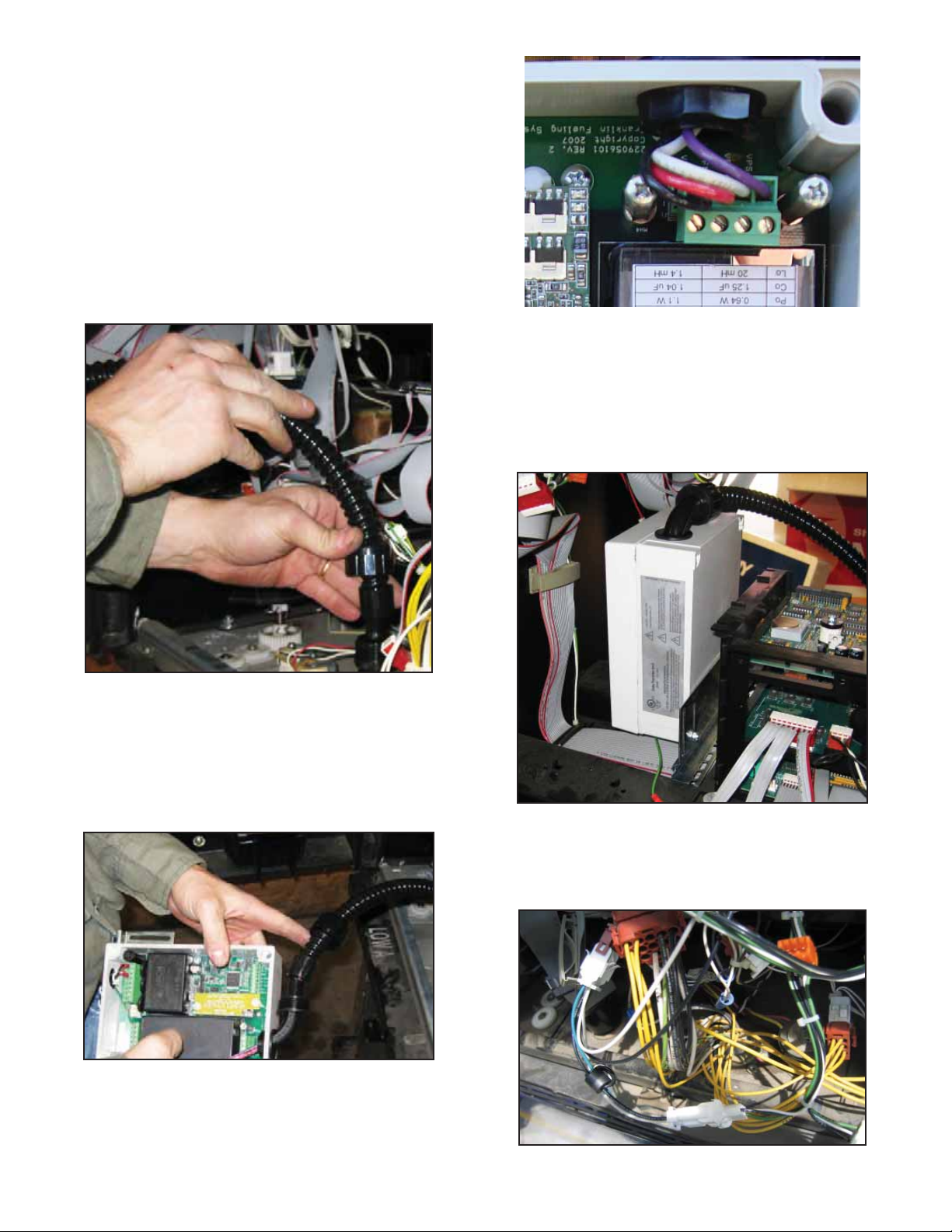
28. Remove nut and bushing from straight conduit
fi tting. Place bushing on one end of fl exible
conduit. Push wires from nipple assembly through
bushing / fl exible conduit and secure fl exible
conduit to straight conduit fi tting using nut.
Figure 12: Attaching Flexible Conduit
29. Remove nut and bushing from 90 degree conduit
fi tting and push fl exible conduit through nut. Put
bushing on unattached end of fl exible conduit.
Push wires from fl exible conduit through the 90
degree conduit fi tting and pull excess wire into
DTU. Attach fl exible conduit to 90-degree fi tting
with nut.
Figure 13: Attach Flexible Conduit to DTU
30. Cut excess wire inside DTU allowing a length of 2”
for terminal block wiring. Strip insulation
3
/
8
” from
ends of wire. Attach wires to DTU terminal block
as follows (DIAGRAM)
Figure 14: Attach Wiring to DTU
31. Reinstall barrier cover using screws that were
removed in step 23.
32. Replace DTU cover.
33. Install the DTU assembly on the horizontal cross
bracket as shown in Figure 15. Use the two
screws, washers, and nuts as supplied in the TS-
DTU/P hardware kit.
Figure 15: Attach DTU Mounting Bracket
34. Find input connector on AC distribution wiring
harness and disconnect.
35. Insert new power harness with ferrites between
input power and AC distribution harness.
Figure 16: Connecting to Dispenser Power

11
Gilbarco Advantage Narrow Frame - DTU Installation
36. Attach ring terminal of DTU ground wire to
dispenser with bolt, nut and star washer.
Figure 17: Attach Ground Wire
37. Use wire-wrap ties to attach excess wires from AC
wiring harness together.
38. Use wire-wrap ties to attach excess wire from DTU
power harness and ground away from door and
gears.
39. Find cable assembly extending from TS-VFM
vapor meter in dispenser hydraulics enclosure.
40. Find wiring from previously installed potted nipple
assembly inside hydraulics enclosure.
41. Find two wire-splice connector kits. Inside hydraulics
enclosure, connect black wire from potted nipple
assembly to black wire from TS-VFM fl ow meter by
placing each lead into an opening in the wire splice
connector and push fi tting closed to lock.
42. Find cable extending from TS-VPS inside
hydraulics enclosure. Cut yellow and blue leads
from end of cable.
43. Find purple and white wires from potted nipple
assembly in hydraulics enclosure. Strip wiring
insulation
3
/
8
" from end of wire.
44. Using wire nuts provided with kit, attach purple
wire from potted nipple assembly to black wire
of TS-VPS and white wire from potted nipple
assembly to white wire of the TS-VPS.
45. Close main doors on Side A and Side B.
46. Engage main door latches located in both option
openings for each side. Refer to fi gure 2 & 3.
47. Tighten the three bolts at the bottom of each main
door assembly. See fi gure 1.
48. Reinstall side A lower dispenser door. Firmly
attach using key lock on right side of door.
12
Gilbarco Encore 300 and 500 - DTU Installation
Gilbarco Encore 300 and 500 Series
This section illustrates the basic components needed
to retrofi t a TS-DTU module into an existing dispenser.
This system can be installed in any “Non-Vapor or Vapor
Ready” dispenser including dispensers with existing
“Balance” or “VacAssist” piping.
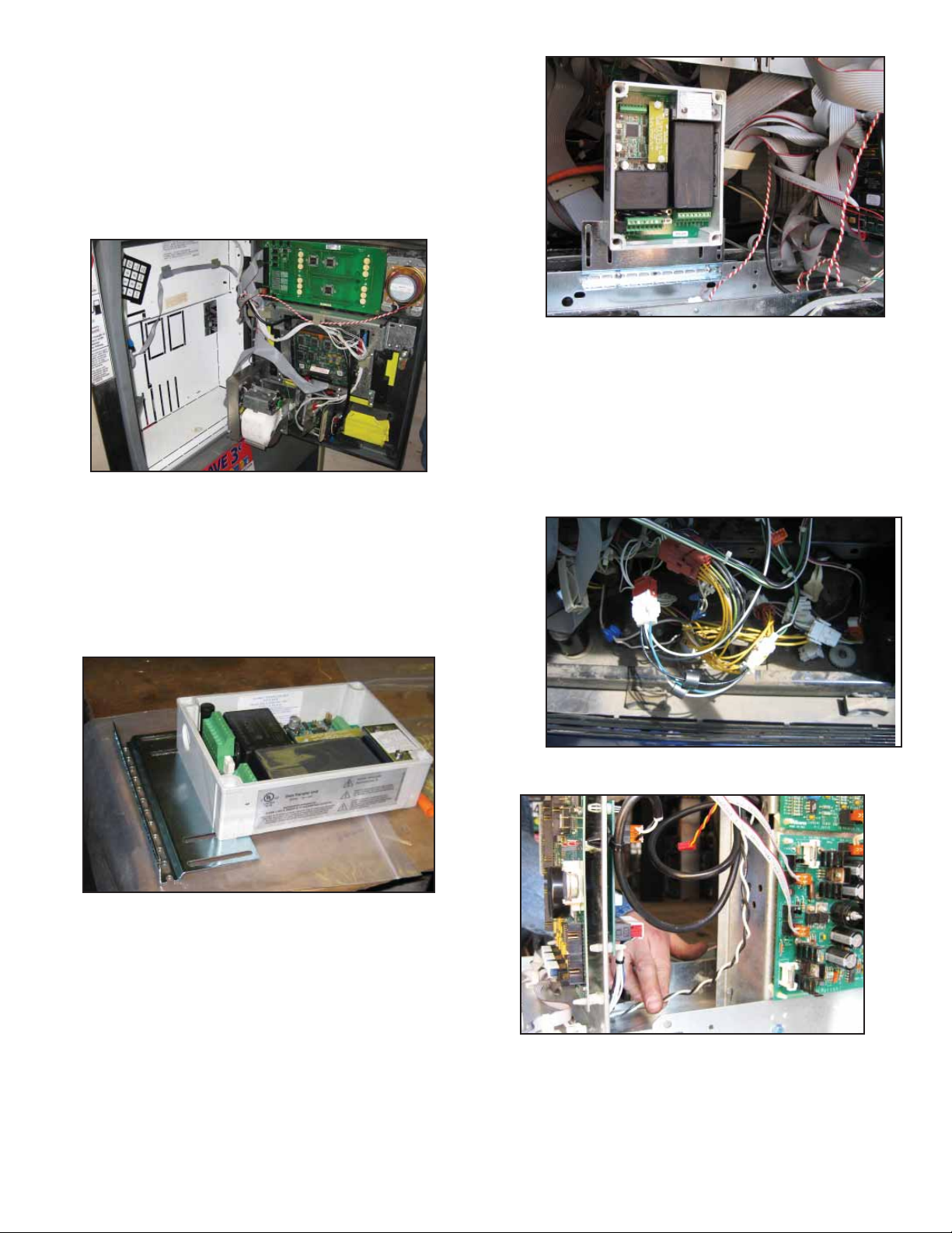
1. Unlock interface doors on both sides of dispenser.
Open two latches on left side of interface door and
open main doors.
Figure 1: Open Doors
2. Find TS-DTU/P from kit and remove brackets,
DTU, and hardware from box.
3. Remove cover from DTU.
4. Install mounting bracket to DTU using two screws,
nuts and washers from hardware provided with
DTU as described in the General Information
section. Make sure the bracket is installed on
correct side as shown.
Figure 2: Install Mounting Bracket
5. Install the DTU assembly on the horizontal
cross bracket as shown in Figure 3. Use
the two screws, washers, and nuts as
supplied in the TS-DTU/P hardware kit.
Figure 3: Mount DTU in Dispenser
6. Find power harness kit part number, 600-0167. Find
the Gilbarco power harness as shown in fi gure 4 of
the Parts List. Remove tie-wraps and uncoil. The
Gilbarco cable will have green ground wire.
7. Inside dispenser, fi nd the incoming power
connection. Attach the new power extension
cable between the original dispenser power
connectors. Notice that the wire colors
match up with the original connection.
Figure 4: Power Distribution Wires
8. Carefully route DTU power wiring harness to DTU.
Figure 5: Power Wiring
9. Route crimp terminal end of harness through
opening in the bottom of the DTU and connect
white lead to terminal block position labeled
NEUTRAL and black lead to terminal block
position labeled L1 on terminal block J1 of DTU.
 Loading...