

Page 1

ZK 313 GB
Installation Instructions 810702-00
Control Valve with ZK Radial Stage Nozzle
Page 2

Contents
Page
Important Notes
Usage for the Intended Purpose.............................................................................................. 3
Safety Note.............................................................................................................................. 3
Warning ................................................................................................................................... 4
Ratings Pursuant to Article 9 of the Pressure Equipment Directive ......................................... 4
Explanatory Notes
Scope of Supply ...................................................................................................................... 5
Description............................................................................................................................... 5
Function................................................................................................................................... 6
Technical Data......................................................................................................................... 7
Pressure/Temperature Rating ................................................................................................. 7
Material.................................................................................................................................... 8
Corrosion Resistance .............................................................................................................. 8
Nominal Sizes.......................................................................................................................... 8
Connections............................................................................................................................. 8
Operation................................................................................................................................. 8
Capacity Charts ....................................................................................................................... 9
Kvs Values and Actuator Selection Data ................................................................................ 10
Operating Procedure
Installation ....................................................................................................................... 11, 12
Commissioning ...................................................................................................................... 12
Operation............................................................................................................................... 13
Maintenance .................................................................................................................... 13, 14
Repairs
Repair.................................................................................................................................... 15
Spare Parts............................................................................................................................ 15
2
Page 3

Important Notes
Usage for the Intended Purpose
The control valve, series ZK 313, is intended solely for cutting off and/or regulating the flow of
fluids consisting of water, steam, or steam condensate.
Its use is permissible only within the allowable limits of pressure and temperature and only if
the chemical and corrosive influences on the pressure equipment are taken into account.
Before installation and operation, a check must be performed to ascertain that the valve is
resistant to the medium in the operational conditions that will exist.
Opening of the valve body and/or structural changes may be performed only if the
manufacturer's written permission is obtained.
Any type of use differing from the usage described above must be considered as improper.
The resulting risk will have to be borne by the user alone. The manufacturer hereby expressly
rejects any claims for any resulting damage.
Safety Note
The control valve ZK 313 must not be installed, removed, commissioned, operated or
maintained by anyone other than qualified staff.
"Qualified staff" are persons who are familiar with the procedures for installation, removal,
commissioning, operation and maintenance of the product, and who have qualifications
appropriate for their work, for example staff who have received the following:
Training as specialists.
Training or instruction in the use of appropriate safety procedures in accordance with the
standards of safety engineering.
Training or instruction in first aid and in accident prevention regulations.
For installation, removal, commissioning, operation and maintenance, every person who
works with the control valve must have read and understood the complete installation
instructions. Furthermore, responsibilities must have been defined clearly and unambiguously
and must be adhered to.
In addition to these installation instructions, the documents issued by the manufacturers of
the actuators, and in particular the safety information contained in these documents, must be
observed.
Usage of the control valve ZK 313 for the intended purpose includes compliance with the
rules and notes in these installation instructions for installation, removal, commissioning,
operation and maintenance.
The operating company must ensure that, whenever the control valve ZK 313 is being
operated, it is in perfect condition.
Working methods that jeopardise safety must not be used.
3
Page 4
Important Notes
Warning
Danger
If the control valve is used in an inexpert or improper manner by unqualified
staff, it can cause danger to life and limb for the user or for third parties,
possibly resulting in death.
During operation, the control valve ZK 313 is under pressure. In this condition,
screws, nuts or bolts must not be slackened. Hot water or steam could flow out
and could cause severe scalding over the entire body.
During operation, the valve might be hot. If the valve is touched when in the
operational condition, severe burns are possible. It must be ensured that,
when handwheels are being operated, the operator wears gloves.
Any installation or removal work may only be performed when the equipment
is at zero pressure and has cooled down. When such work is to be done, the
pressure in the pipes upstream and downstream of the valve must have been
reduced to zero and the valve must have cooled down sufficiently. It must be
ensured that, during the work, the system section in which pressure has been
reduced to zero cannot be accidentally put back into operation. The shut-off
valves needed for this purpose must be separately secured and marked.
In addition, it must be ensured that the actuators of the valve are not in the
connected state. The connection to the energy supply (electric, pneumatic,
hydraulic) must be disconnected and must be secured to prevent it from being
operated accidentally. One or more warning notices, for example containing
the text "DO NOT SWITCH ON", must be displayed in a clearly visible manner
at each operating element.
(continued)
Ratings Pursuant to Article 9 of the Pressure Equipment Directive
Gaseous Liquid
Fluid
1212
Use
Category
Nominal size of connection, DN
CE marking
The control valve may only be used in accordance with the above-mentioned ratings pursuant
to Article 9 of the Pressure Equipment Directive. Any other type of use must be considered as
improper.
No Yes No Yes
Exception
according
to Art.3.3
25 32 – 100 125
No Yes Yes Yes ---
I II III
≥150
IV
(safety
equipment)
---
4
Page 5
Explanatory Notes
Scope of Supply
Control valve ZK 313 with or without an attached actuator, according to the order
Installation instructions for the control valve
Parts list with drawing
Operation instructions for the actuator
Acceptance certificates according to the order
Description
The control valve ZK 313 is used to reduce large differential pressures. It is used mainly in
industrial plants and power stations in which ease of maintenance and high resistance to
wear are required.
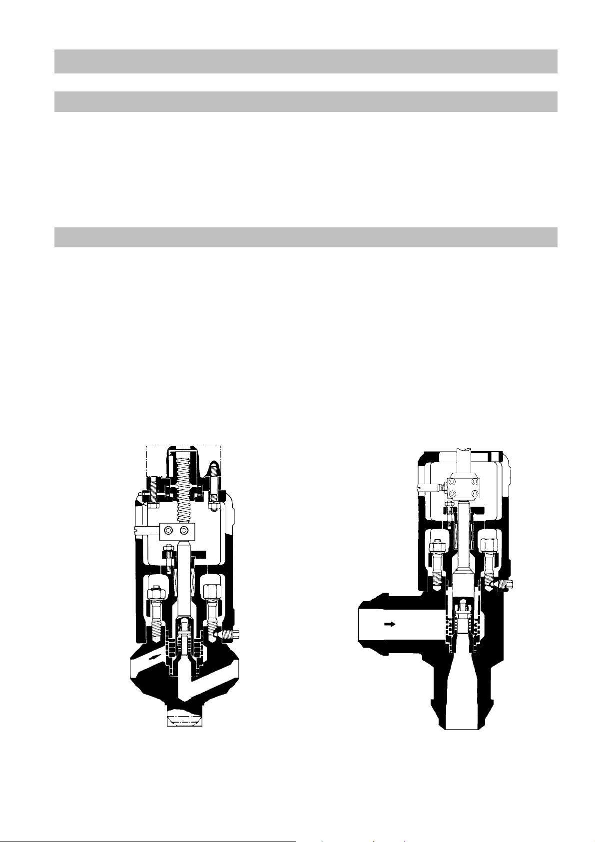
The valve consists of the valve body, a yoke suitable for the various actuators, and a ZK
radial stage nozzle with valve plug integrated in the valve body to act at the control element.
The valve body comes in two different sizes: The small size DN 25 - DN 80 is available as
straight-through (ZK 313-D/...) or angle (ZK 313-E/...) version. For larger flowrates open-die
forged bodies DN 80 - DN 150 in Z shape (ZK 313-Z0/...) or as angle versions (ZK 313-E0/...)
are also available.
The control valve can be operated by means of various actuators, e.g. electric rotary
actuators, pneumatic actuators and lever actuators, or by means of a handwheel.
Control valve ZK 313-D/11 DN 25 – DN 80 Control valve ZK 313-E0/13 DN 80 – DN 150
5
Page 6

Explanatory Notes
Function
Every control valve is equipped with a ZK radial stage nozzle.
This is a system comprising several sleeves nesting within one another and containing radial
orifices drilled in them. By rotation of the sleeves, the orifices are shifted relative to one
another, thus forming a large number of throttling points in parallel, with turbulence chambers
(expansion chambers) in between.
The throughput through the ZK radial stage nozzle is set by means of the valve plug.
Depending on its position, this valve plug opens up the individual orifices partially or
completely, thus producing different flow rates.
As a result of this design, the pressure drop is reduced in steps and the medium flowing
through is split up into many partial flows. This ensures high resistance to wear and reduces
the noise level.
The control valve ZK 313 is also equipped with a dual (tandem) shut-off. At the moment of
closing and at the beginning of opening the flow velocity at the valve seat is zero, which
means that wire drawing and wear on the seating surfaces is prevented. The lift difference
between the control piston and the leading valve plug is balanced out by disc springs.
(continued)
The closing process of the control valve ZK 313 with radial stage nozzle:
Valve plug in control position Valve plug interrupts flowrate Main valve plug in closed
position
6
Page 7

Explanatory Notes
Technical Data
Important
For the technical data of the control valve ZK 313, see the name plate.
Name plate Specifications
(continued)
Type with nominal size of body
Gestra serial number
ZK313-D/11
TYP
1234
NR
50
DN
PN
Düse/Nozzle
11 LIN
300
°C
510 120
bar
psig
1
) If there is no rated pressure stated on the name plate, the maximum allowable pressure
30
20
10
0
570
Nominal size of connection [DN]
Rated pressure [bar]
Valve stroke [mm]
Kvs value, characteristic curve
Max. allowable temperature [°C] 1)
Max. allowable pressure [barg] 1)
limits are stated together with the associated temperatures.
Example: °C 300 | 570
barg 510 | 120
2
) The statement of differential pressure corresponds to valve inlet pressure minus valve
outlet pressure.
The scope and layout of the name plate data comply with EN 19.
Pressure/Temperature Rating
Important
In the installation instructions, standard pressure/temperature ratings for
materials 1.5415 and 1.7380 are described. For possible deviations, please see
the name plate of the control valve.
Max. allowable inlet temperature TMA [°C] 200 400 530 570
Max. allowable pressure (1.5415) PMA [bar g] 535 433 165 –
Max. allowable pressure (1.7380) PMA [bar g] 550 503 326 184
Max. allow. differential pressure ∆PMX [bar]
300 with additional stage 370
7
Page 8

Explanatory Notes
Material
Important
In the installation instructions, standard materials are described. For possible
deviations, please see the parts list supplied.
Body (to choice) 15 Mo 3 (1.5415)
Internals X 35 CrMo 17 (1.4122)
Gland packing Pure graphite
Corrosion Resistance
(continued)
10 CrMo 9 10 (1.7380)
X 90 CrMoV 18 (1.4112)
X 20 CrMoV 12 1 (1.4922)
If the unit is used for the intended purpose, its safety is not impaired by corrosion.
Nominal Sizes
The control valve ZK 313 is delivered with bodies of nominal size DN 25, DN 50, DN 80,
DN 100 and DN 150. Different connection sizes are possible as special versions.
To determine the nominal size, the nominal size of the control valve's connection, which is
stated on the name plate, is definitive.
Connections
The control valve ZK 313 is normally delivered with butt-weld ends. Alternatively if desired,
socket-weld ends or flanges are possible.
Operation
The control valve ZK 313 is suitable for the following actuators:
ZK 313-../11 Version with insert bush F10 of form B1 to DIN ISO 5210 or for attaching
an electric rotary actuator or a handwheel, whichever is desired
ZK 313-../12 Version with insert bush F14 of form B1 to DIN ISO 5210 or for attaching
an electric rotary actuator
ZK 313-../13 Electric linear actuator
ZK 313-../20 Pneumatic diaphragm-actuator
ZK 313-../30 Lever for quarter-turn actuator (next to valve)
ZK 313-../31 Lever prepared for attaching a quarter-turn actuator to the valve
ZK 313-../40 Hydraulic cylinder
8
Page 9

Explanatory Notes
Capacity Charts
(continued)
Cold water: Use open-die forged bodies ZK 313-E0/ or ZK 313-Z0/ for volume
flowrates > 100 m³/h.
Hot water ts -5K The diagrams show the max. flowrates of hot and cold water
at the extreme control position for nozzles up to ∆p max 300 bar.
9
Page 10

Explanatory Notes
Kvs Values and Actuator Selection Data
Important
In the installation instructions, standard values are described. For possible
deviations, please see the name plate of the control valve.
DN Characteristic
25 – 80 linear/equal %. 300 1 1.5 2.3 3.6 5.5 8 11 13
25 – 80 linear/equal %. 370 4.5 7 9.5 10.5
80 – 150 linear/equal %. 300 2.3 3.6 5.5 11 14.5 17
80 – 150 linear/equal %. 370 4.5 9 12
(continued)
∆p max.
[bar]
Kvs [m³/h]
Valve stroke
DN
25 – 80 35
80 – 150 35
[mm] Revs./Stroke
Type/size of
Max. admissible torque
for opening. [Nm]
7 120 F10 – B1
5.8 310 F14 – B1
7 120 F10 – B1
5.8 310 F14 – B1
actuator
DIN ISO 5210
10
Page 11

Operating Procedure
Installation
It is highly advisable to have the installation work done by qualified staff in the manner
described by these installation instructions. The manufacturer will not accept liability for
damage resulting from improper installation.
In addition, the installation instructions issued by the actuator manufacturers must be
observed.
During installation, it must be ensured that the installation space surrounding the valve is
large enough for the purposes of installation, removal, operation and maintenance.
Please check whether the weight of the valve makes an additional support necessary.
In the case of installation with a horizontal valve-spindle and a pneumatic actuator, the weight
of the actuator must be supported separately.
For the installation work, hoisting gear must be chosen which is designed for the weights
concerned.
The control valves may only be hoisted by the body and/or by the yoke of the valve.
During hoisting, damage to the actuator, the stuffing box and the lubricating device must be
avoided.
The control valve ZK 313 is welded into place directly into the pipe or is mounted between
flanges, depending on the connection facilities that are present.
In the case of welding-connections, the statutory and industrial rules for welding-connections
must be observed. Before welding, the welding locations must be cleaned.
Important
The valve is welded into place in the assembled state; any heat treatment that
is necessary for the welded joints can likewise be performed in the assembled
state. It must be ensured here that the region affected by the heat is limited to
the welded joints.
After the valve has been welded into place, it is recommended that it should
then be opened fully and flushed with water.
Flushing with caustic agents may only be performed if approved by the
manufacturer.
In the case of flange connections, precise positioning of the seals between the flanges must
be ensured. Before installation, the sealing surfaces must be cleaned.
Before the control valve is installed, all transportation packaging and all coverings of
connections must be removed.
11
Page 12

Operating Procedure
(continued)
Installation
(continued)
Important
Attention must be paid to the direction of flow. It is indicated by an arrow on the
body.
Basically, the valve can be installed with any orientation. As viewed in the direction of flow,
the normal installation orientation of the control valve is horizontal with the spindle vertical
and the stuffing box pointing upwards.
In the case of angle valves, flow takes place over the valve plug.
In the case of units with actuators, the installation rules issued by the actuator manufacturers
must be observed.
Commissioning
The task of commissioning the control valve is performed when the valve is put into operation
for the first time, and also after repairs.
Commissioning may only be carried out by qualified staff who have read and understood the
installation instructions.
For the actuators, the additional documents issued by the manufacturers must be observed.
Before commissioning, a check must be performed to ensure that all fastenings have been
securely tightened.
Commissioning does not require any additional work on the valve.
Unless agreed otherwise, the control valve is delivered in the closed state. The travel
distance of the valve plug is stated on the name plate.
During the task of commissioning, all connections and seals on the valve must be checked for
leaks. Any leaks must be corrected immediately. In the case of flanged connections, this is
done by tightening the nuts; it can also be done on the valve by tightening the stuffing box if
necessary.
In the case of pipes at high temperatures, the valves should not be suddenly exposed to the
high temperatures. Here, slow warming-up should be performed.
12
Page 13

Operating Procedure
Operation
The control valve ZK 313 may only be operated by qualified staff who have read and
understood the installation instructions. Additional installation instructions issued by the
manufacturers of the actuators must be observed.
Danger
During operation, the control valve ZK 313 is under pressure. In this condition, if
flanged connections, sealing plugs or the stuffing box is slackened, hot water or
steam will flow out and could cause severe scalding over the entire body. There
is danger to life and limb for the user or for third parties, possibly resulting in
death.
During operation, the valve is hot. If the valve is touched when in the
operational condition, severe burns are possible. It must be ensured that, when
handwheels are being operated, the operator wears gloves.
During operation, the spindle is moved. The moving parts of the control valve
and of the actuator must definitely not be touched; otherwise, your hands might
be crushed.
(continued)
Maintenance
The control valve ZK 313 may only be maintained by qualified staff. "Qualified staff" are
persons who have the necessary qualifications for their work and are familiar with the
product.
The additional documents issued by the actuator manufacturers must be observed.
Danger
During operation, the spindle is moved. The moving parts of the control valve
and of the actuator must definitely not be touched; otherwise, your hands might
be crushed.
13
Page 14

Operating Procedure
(continued)
Maintenance
(continued)
The following maintenance work must be performed:
Type of
Time interval Activities
maintenance
Inspection Quarter-yearly Checking the stuffing box for leaks 1) (visual inspection)
Inspection Quarter-yearly Checking that connections, body seal, valve spindle and
threaded spindle are free of wear, are clean, and are not
leaking (visual inspection)
Inspection Quarter-yearly Checking of seat tightness
Lubrication Quarter-yearly Lubricating the spindle bearing with lithium-saponified
grease with penetration grade 2 with MoS2 additive 2)
Inspection Annually Checking that the fastening screws of the valve actuator are
seated securely, and tightening them if necessary
Inspection Every three
years
Checking by Gestra specialists to ensure that the internal
parts and threaded spindle are not damaged
1
) Replenishment or exchange of the stuffing box rings may only be performed when there is
no pressure in the valve. In particular, the safety information and danger notes in the
section entitled "Important Notes" must be observed.
Important
The task of opening the body may only be performed by specialists from
Gestra.
2
) Lubricants recommended by the manufacturer are:
Shell Retinax AM with MoS
2
DEA Glissando MEP2
14
Page 15

Repairs
Repair
Repair work on the control valve ZK 313 may only be performed by specialists from Gestra.
Opening the valve body and making structural changes are regarded as being improper
activities.
The resulting risk will have to be borne by the user alone. The manufacturer hereby expressly
rejects any claims for any resulting damage.
For maintenance and repair, only original Gestra spare parts may be used.
Spare Parts
For every control valve ZK 313, a separate parts-list with the associated overall drawing is
supplied as well by the manufacturer.
When spare parts are being ordered, the necessary spare-part numbers must be taken from
that list.
Spare parts can also be ordered directly from Gestra by quoting the Gestra serial number
stated on the name plate.
15
Page 16

GESTRA Gesellschaften • GESTRA Companies • Sociétés GESTRA • Sociedades Gestra • Societã GESTRA
Vertretungen weltweit ● Agencies all over the world ● Représentations dans le monde entier ● Representaciones en todo el mundo ● Agenzie in tutto il mondo
Great Britain Italia
Flowserve Flow Control (UK) Ltd.
Burrel Road, Haywards Heath
West Sussex RH 16 1TL
Tel. 00 44 14 44 / 31 44 00
Fax 00 44 14 44 / 31 45 40
E-mail: sales@flowserve.com
Flowserve S.p. A
Divisione Italgestra
Via Prealpi, 30 – 20032 Cormano (MI)
Tel. 00 39 02 / 66 32 51
Fax 00 39 02 / 66 32 55 60
E-mail: info@italgestra.it
France Portugal
Flowserve Flow Control S.A.S.
10 Avenue du Centaure, BP 8263
F-95801 CERGY PONTOISE CEDEX
Tél. 00.33.1 / 34 43 26 60
Fax 00.33.1 / 34 43 26 87
E-mail: contact@gestra.fr
Flowserve Portuguesa, Lda.
Av. Dr. Antunes Guimarães, 1159
Porto 4100-082
Tel. 0035122/6198770
Fax 00351 22 / 6 10 75 75
E-mail: gestra@gestra.pt
España
GESTRA ESPAÑOLA S.A.
Luis Cabrera, 86-88
E-28002 Madrid
Tel. 00 34 91 / 5 152 032
Fax 00 34 91 / 4 136 747; 5 152 036
E-mail: gestra@gestra.es
__________________________________________________________________________
810702-00/502 ©2001 GESTRA GmbH Bremen Printed in Germany
 Loading...