

Page 1

Valtek XL Series
High-Performance
Positioner
GENERAL INFORMATION
This bulletin is designed to assist in installing, calibrating, troubleshooting and performing maintenance as
required for the Valtek® XL Series high-performance
positioner.
Product users and maintenance personnel should thoroughly read and strictly follow the instructions contained in this bulletin prior to operating the positioner.
Any questions concerning this product should be directed to a Flowserve representative.
To avoid possible injury to personnel or damage to valve parts, WARNING and CAUTION
notes must be strictly followed. Modifying this
product, substituting non-factory parts or using maintenance procedures other than outlined could drastically affect performance and
be hazardous to personnel and equipment.
NOTE: The air supply should conform to ISA
Standard S7.3 (a dew point at least 18° F / -8° C
below ambient temperature, particle size below 5
microns, oil content not to exceed one part per
million).
The XL Series positioner features an adjustable gain of
400-1100:1. The medium gain setting is standard on
size 25 actuators, while the high gain setting is standard
on size 50 and larger actuators (refer to ‘Gain Adjustment Procedure’ section for further details.)
All positioners come with one of two types of cams:
a linear characteristic cam for use on linear actuators or
a combination linear / modified equal percentage
characteristic cam for rotary actuators. Refer to the
‘Rotary Actuator Cam Characteristic’ chart on page 4 for
specific installed characteristics.
The XL high-performance positioner is a two-stage
device and is designed for use in control loops where
fast response is required. The XL positioner is designed
to be modular and use the P/P module for 3-15 psi input
signal or the NT 3000 Series Transducer Module for
4-20 mA input signal.
The XL high-performance positioner is designed as a
four-way device, but can easily be converted to a threeway device by plugging one of the output ports.
NOTE: The XL high-performance positioner must
use the I/P NT 3000 Transducer. The I/P 2000 Transducer is not acceptable for use with the XL Series
Positioner.
The XL positioner can handle supply pressures up to
150 psi; thus, a supply regulator is usually not required.
However,
matic positioners and a coalescing filter is required for
I/P positioners.
Valtek No. 10077320
a five micron air filter is required for pneu-
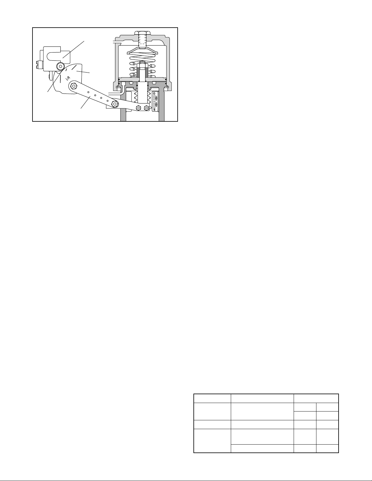
POSITIONER OPERATION
The positioner schematic (Figure 1) shows an XL Series
positioner connected for double-acting service on a
linear actuator. Tension on the feedback spring provides feedback to the positioner, which varies as the
stem position changes. The spring-loading force is
applied through the feedback linkage and cam to the
positioner’s input capsule.
Instrument signal pressure is applied between the diaphragms in the input capsule. Therefore, the input
capsule serves as a force-balance member, matching
the valve stem position (as measured by tension on the
feedback spring) to the instrument signal.
When the opposing forces balance exactly, the system
will be in equilibrium and the stem will be in the exact
position called for by the instrument signal. If the opposing forces are not in balance, the input capsule will move
up or down and, by means of the pilot-valves, will
45-1
Page 2

Supply Seat
Upper Pilot
Poppet
Exhaust Seat
Port No. 1
Restriction
Supply
Pilot Valve
Capsule
Exhaust Seat
Port No. 2
Lower Pilot
Poppet
Supply Seat
Balance Adjustment
Input Capsule
Figure 1: XL Positioner Schematic for Air-to-Open
change the output pressures, moving the stem until the
tension on the feedback spring opposes exactly the
instrument signal pressure.
The sequence of operation is as follows: An increase in
instrument signal pressure forces the input capsule
downward. Displacement of the capsule in turn moves
the flapper away from the detecting nozzle. This allows
a larger flow rate through the nozzle, decreasing the
pressure exerted on the top of the pilot valve capsule.
Supply air biases the pilot-valve in an upward direction.
As the capsule moves up, it will close the exhaust seat
of the upper pilot poppet and open the supply seat,
which applies increased air pressure to the bottom
cylinder port. At the same time, the pilot-valve capsule
will open the exhaust seat for the lower pilot poppet;
thus, decreasing pressure to the top cylinder port.
This difference in pressure will drive the piston upward,
which stretches the feedback spring until the spring
tension exactly opposes the force resulting from the
instrument signal pressure. At this point, the flapper will
be moved toward the detecting nozzle to restore the
pressure above the pilot-valve capsule to its equilibrium
value. As a force-balanced condition is approached, the
pilot-valve capsule will be forced back to a neutral
position where the pilots are neither supplying air to, nor
exhausting air from, their respective sides of the piston.
A decrease in instrument signal pressure reverses the
described actions and causes a proportional downward
movement of actuator piston and stem.
Installation of XL Series Positioner on
Double-Acting, Linear-Cylinder Actuators
When installing or retrofitting the XL Series positioner
on all sizes of linear actuators, proceed as follows:
NOTE: For retrofitting to an actuator equipped with
a Beta or 80R positioner, the same bracket, follower
arm and take-off arm can be used (begin with step 4).
Cylinder
Zero Adjustment
Feedback
Spring
Detecting
Nozzle
Flapper
Range
Adjust Screw
Piston
Cam
Follower
Arm
Upper Diaphragm
Instrument Signal
Lower Diaphragm
Take-off Arm
Size 25, 100, 200 Size 50
Figure 2: Positioner Mounting Bracket
Hole
A
Air-to-Open Air-to-Close
(Air-to-Retract) (Air-to-Extend)
Return Spring
Cam
Positioner
Base
Figure 3: Return Spring / Cam Mounting
(viewed from positioner’s right side)
O
S
Hole B
45-2
Flowserve Corporation, Valtek Control Products, Tel. USA 801 489 8611
Page 3
Cam
elytSevlaVcitsiretcarahCoTriA
DLV/TSS
lauqEdeifidoM
egatnecreP
nepOesolC
BC
DLV/TSSraeniLCB
olFxaM
lauqEdeifidoM
egatnecreP
1MAC2MAC
raeniL1MAC2MAC
Start
Position
Roller
Bearing
Cam
Follower Arm
Figure 4: Cam Alignment
cam roller-bearing when the valve is seated. (See
Figure 4.) Tighten the stem clamp.
10. For air-to-open action, tube ‘output 2’ to the top of
cylinder and ‘output 1’ to the bottom of cylinder. For
air-to-close action, tube ‘output 1’ to top of cylinder
and ‘output 2’ to the bottom of the cylinder.
NOTE: For three-way diaphragm actuators plug
output 2, tube output 1 to desired side of
diaphragm.
11. Attach supply air and instrument tubing or wiring.
CAUTION: Signal air pressure higher than 30
psi may damage the module gauge and instrument signal capsule; a 3-15 psi instrument signal is recommended on the pneumatic module.
NOTE: When retrofitting the XL positioner to an
actuator equipped with other positioners, remove
the existing positioner, tubing and associated bolting.
See tubing instructions in Step 10.
1. Place the stem clamp onto the actuator stem with
the boss on the right side as illustrated in Figure 1.
2. Mount positioner bracket to the yoke leg which has
the stroke indicator plate attached. (See Figure 2.)
3. Mount the take-off arm on the stem clamp so the
slots in the end of the arm step upward toward the
cylinder. The holes in the follower arm should line
up with the slots in the take-off arm.
4. For air-to-retract action, install the cam in the positioner, with L-R facing outward. For air-to-extend
action, L-D side of the cam should face outward.
When installing the cam, position it so the center
mark on the cam lines up through the center of the
cam roller-bearing on the cam follower arm with the
follower arm perpendicular to the base of the positioner. (See Figures 3 and 4.) Apply a small amount
of grease to the bent end of the return spring and
feed it through the hole in the cam. Loop the other
end of the return spring over the screw and screw it
into the positioner base.
NOTE: Screw head will not bottom out.
5. Feed the appropriate follower arm onto the cam
shaft boss with the hole markings facing outward.
Secure with the lockwasher and nut. (See Figure 7.)
6. Fasten the follower pin into the correct hole in the
follower arm for the desired stroke length of the trim.
(Stroke lengths are stamped on the follower arm.)
7. Feed the follower pin into the appropriate slot in the
take-off arm. (See Figure 4.) Tighten the nut on the
pin and grease the slot where the pin rides.
NOTE: A light industrial grease is recommended. Failure to lubricate the pin can cause
premature wear.
8. Using three screws, mount the positioner to the
brackets as shown in Figure 2.
9. If necessary, adjust the height of the stem clamp so
the first line of the cam aligns with the center of the
Flowserve Corporation, Valtek Control Products, Tel. USA 801 489 8611
Reversing Air Action of XL Series
Positioners on Linear Actuators
Reversing the air-action of the positioner is simple. No
additional parts are required, although the tubing will
need to be rerouted on the linear actuator.
To reverse the air-action of XL series positioners on all
sizes of linear actuators, proceed as follows:
1. Using the ‘Spring Cylinder Linear Actuators’ Installation, Operation, Maintenance Instructions, reverse
the air-action of the actuator.
2. Disengage the return spring from the cam and
remove the cam from the cam shaft.
3. Reverse the cam, return spring and tubing for the
desired air-action by referring to Steps 4-8 in the
‘Installation of XL Series Positioner on Linear Actuators’ section of these instructions.
Installing XL Series Positioner on Rotary
Actuators
Proceed as follows when installing the XL Series positioner on all sizes of rotary actuators if the cam and
follower arm are not already installed, otherwise refer
directly to step 7.
1. With the desired cam and its identification letter
facing toward the cam shaft, slide the cam onto the
end of the cam shaft with the shorter shoulder. (Ref er
to Table I to determine desired cam characteristic.)
Fasten with the star lock washer and nut.
2. Insert the follower arm into the back recess of the
Table I:
Rotary Actuator Cam Characteristic Chart
45-3
Page 4

Follower
Pin
Follower
Arm
positioner. Figures 11 through 16 show the shaft
rotation versus instrument signal of a valve (Valdisk,
ShearStream or MaxFlo). These graphs should be
used when visually checking the valve shaft rotation
versus positioner signal relationship.
Cam
Read Cam
Characteristics
from this side only
Actuator Lever Arm
Figure 5: XL Series Positioner
Installation on Valtek Rotary Actuator
positioner with part identification number facing out to
the right side. Slide the cam shaft through the inner
bearing and then slip flatted hole of the follower arm
over the longer stepped shoulder of the cam shaft.
3. Place a small amount of thread-locking compound
(Loctite No. 222 or equivalent) to the threaded portion
of cam shaft nut. Slide the cam shaft nut through outer
bearing and screw it onto the cam shaft. Tighten the
cam shaft together firmly so that the follower arm is
securely clamped. Also, make sure the cam is tightly
secured to cam shaft. Check to be sure there is no
slippage. Apply a small amount of grease to the bent
end of the return spring and feed it through the hole in
the cam. Loop the other end of the return spring over
the screw and screw it into the positioner base.
NOTE: Screw head will not bottom out.
4. Rotate the zero adjustment arm back into place and
reinstall the feedback spring.
5. If the follower pin is present, insert it into the hole in the
actuator lever arm and drive it firmly into place with a
hammer. (See Figure 5.)
6. Apply grease to the sliding surfaces of the follower
arm before mounting the positioner to the transfer
case. When mounting the positioner to the transfer
case, make sure to guide the follower arm so the pin
slides in the slot on the follower arm. (See Figure 5.)
Fasten the positioner to the transfer case with the
three mounting screws. Push up on the cam to verify
the pin is riding in the follower arm slot or remove
transfer case cover plate to inspect.
CAUTION: Failure to replace the cover plate before pressurizing or operating the actuator will
cause damage to the shaft since the cover plate
houses a shaft-support bearing.
Depending on the positioner cam side selected, the
valve flow characteristic may be linear or equal percent when compared to the instrument signal to the
Reversing Air-Action of XL Series
Positioners on Rotary Actuators
Reversing the action on rotary actuators is achieved by
mounting the yoke to the opposite side of the transfer
case. Refer to maintenance instructions ‘Spring Cylinder
Rotary Actuators’ for details.
Note: When reversing action on rotary actuators, also
change cam. (See Table I.)
Return Spring
Read Cam
Characteristics
Screw
Lock
from this side only
Cam
Washer
Grease Here
Nut
Cam Shaft
Figure 6: Cam Return Spring Installation
POSITIONER CALIBRATION
Introduction
Valtek positioners are calibrated at the factory; however, due to shipping and handling, it may be necessary
to check the calibration before operating the valve. The
XL positioner, for strokes 3/4-inch and above, can be
calibrated to a range of 3-15; two-way split range, 3-9,
or 9-15; and three-way split ranging, 3-7, 7-11, 11-15
psi using the standard feedback spring. An alternate
red colored feedback spring on linear actuators is used
for strokes less than 3/4-inch.
WARNING: When stroking the actuator during calibration, keep hands, hair and clothing away from
moving parts. Failure to do so may cause serious
personal injury.
Note: Positioners and I/Ps are calibrated at the
factory. Use mechanical adjustments in positioner
for calibration. Zero and span on the I/P should not
be used to calibrate valve.
For calibration, proceed as follows:
1. For 3-15 or 3-9 psi range, loosen by hand the zero
adjustment locking knob and adjust the zero adjustment knob until the valve begins to stroke with more
than 3 psi signal (for 9-15 psi range adjust to 9 psi).
2. Loosen the range adjustment locking screw no
more than 1/8 turn.
45-4
Flowserve Corporation, Valtek Control Products, Tel. USA 801 489 8611
Page 5

Output 1
Zero Adjustment
Lock Knob
Zero Adjustment
Knob
Span Adjustment
Cam Follower
Arm (Range Arm)
Output 2
Balance
Adjusting
Screw
Feedback
Spring
Figure 7: Positioner Adjustments
3. With a Phillips screwdriver adjust span adjustment
so valve is at full stroke with more than 15 psi for 3-15
or 9-15 psi range (adjust to 9 psi for 3-9 psi range).
4. Return to 3 psi (or 9 psi for 9-15 psi range) and
check the zero. Repeat steps 1-4 if necessary.
5. Tighten the zero adjustment lock knob and span
adjustment lock knob.
6. Use the same procedure for three-way split range.
Positioner Balance Adjustment
CAUTION: Balance is preset at the factory. If balance adjustment becomes necessary, make changes
carefully and slowly, allowing the positioner to respond before continuing adjustments. Check balance pressure frequently to ensure correct values.
Balance adjustment is set at the factory and normally
should not need adjustment. Balance adjustment (output pressure level) permits the equilibrium pressure in
both sides of the actuator piston to be raised or lowered.
The actuator pressure level of output 1 and 2 should be
approximately 75 to 80 percent of the supply pressure.
When actuator springs are used there will be a pressure
difference between output 1 and 2; the average pressure of both ports should be 75 to 80 percent of the
supply pressure. The minimum recommended supply
pressure is 60 psig.
pressure was used on a fail closed actuator, the balance pressure should be adjusted so that output 1
reads approximately 85 psig and output pressure 2
For example, if 100 psig supply
Feedback Spring
Arm
Span
Adjustment
Locking Screw
Cam
Orifice Screw
Pilot Relay
Assembly
Supply Port
reads approximately 70 psig. The average of these two
pressures is 77.5 percent of the supply pressure.
If necessary, adjust the output pressure level using the
following the procedure:
1. If output pressure level is low, before adjusting, check
for leaks in tubing connections between the positioner and actuator and check supply pressure.
2. Make certain there is no process force or pressure
in the valve (The valve should be removed or
isolated from the process.)
3. On positioners without gauges, connect gauges to
‘output 1’ and ‘output 2’ lines.
4. Remove rubber cap over balance adjustment. (See
Figure 7.)
5. Apply full actuator operating pressure to the positioner supply port.
6. Set input signal to midscale (9 psi for 3-15 psi
span). Output pressure level cannot be adjusted
with actuator against valve seat or travel stops.
Allow actuator pressure to stabilize.
7. Observe the pressure gauges. If reading is not
correct, turn balance adjustment screw about 1/8
turn at a time and wait about 20-30 seconds for
pressure to stabilize (counterclockwise to increase
pressure). Continue until output pressure level of
the higher pressure gauge is approximately 80
percent of supply.
8. Replace rubber cap over balance adjustment screw.
Flowserve Corporation, Valtek Control Products, Tel. USA 801 489 8611
45-5
Page 6

Figure 8: Close-up of Gain Adjustment
Gain Adjustment Procedure
The unique gain adjustment on the XL positioner provides a means to increase or decrease the responsiveness of the valve / actuator / positioner system. Increasing the gain makes the valve more responsive and faster,
while decreasing the gain makes the system less sensitive and slower to respond (with increased damping).
The gain is infinitely adjustable between its highest and
lowest settings. For convenience, three marks indicate
high (H), medium (M) and low (L) gain. Most sizes of
actuators will respond well to a medium (M) gain setting. All XL positioners are factory-set on the medium
(M) gain setting. Unique actuator / valve configurations
may require a gain adjustment at the factory or in the
field.
1. Before adjusting the gain, place the controller on
manual and isolate the valve from the process.
2. Turn off the supply air to the control valve actuator.
3. Using a 5/64-inch Allen wrench,
upper and lower lock screws
Do not loosen the spacer nut. (See Figure 9.)
4. By grasping the adjust lever, carefully rotate the
gain adjust assembly to the desired position.
CAUTION: To avoid damaging the gain adjust
connecting spring mechanism. Make sure both
the upper and lower gain adjust plates rotate
together. When they are rotated to the new
position, the connecting spring should be perpendicular to the plates.
5. When the gain is set to the desired position, firmly
tighten both lock-down screws.
6. Turn on the supply pressure. Check the actuator
responsiveness by providing a step signal to the
positioner. When the gain is set as desired, check
the valve zero and span calibration and re-calibrate
if needed.
7. Return the valve to service.
loosen both the
about one half turn.
Spacer Nut
(Do not
loosen)
Upper
Lock Screw
Lower
Lock Screw
Adjust Lever
Figure 9: Gain Adjustment
Calibrating I/P Module Zero and Span
Settings
NOTE: Although calibration can be accomplished
using the output pressure gauge on the I/P module,
its accuracy is ±3 percent. The standard gauge
should be removed only for calibration and more
accurate calibration equipment of ±0.1 percent of
span should be used. The pressure gauge port is
1
/8-inch NPT. Calibration manifolds are available
from the factory (Part No. 97370).
Circuit Board
Mounting Screws
Grounding Screw
Zero
Adjustment
Span
Adjustment
Minimum Pressure
Cutoff Adjustment
Terminal Block
Current Loop
Termination (-)
Current Loop
Termination (+)
Figure 10: NT 3000 Module Circuit Board
(housing cover removed)
45-6
Flowserve Corporation, Valtek Control Products, Tel. USA 801 489 8611
Page 7

1. Connect the I/P module to a supply pressure between 30 to 150 psi.
2. Remove I/P module housing cover. (See Figure 10.)
WARNING: Be certain power to the I/P module is
disconnected before removing the housing
cover in explosive atmospheres; otherwise personal injury may occur.
3. Before adjusting the zero and span, be certain the
MPC feature is disabled. Refer to Step 7 in the
‘Adjusting the Minimum Pressure Cutoff Feature’
section.
4. Connect a current source to the terminal block on
the circuit board.
NOTE: The zero and span adjustments are
multi-turn potentiometers (pots) that have no
stops on the ends of their travel; however, they
have a slip clutch to prevent damage from overadjustment. The pots also make a clicking
noise when they have reached the limits of their
adjustment.
5. Apply a 4.0 mA signal to the input. Locate and
adjust the zero trim pot to achieve a 3.0 psi output.
Output will increase with clockwise rotation of zero
trim pot. If calibrating an I/P module with a 10-50 mA
input signal, apply a 10.0 mA signal to the input.
6. Increase the input signal to 20.0 mA (50 mA for 1050 mA units). Locate and adjust the span trim pot to
achieve a 15.0 psi output. The output will increase
with clockwise rotation of the span.
7. Recheck the zero setting by repeating Step 5. The
span adjustment may affect the zero setting.
8. Repeat Steps 5, 6 and 7 until the proper adjustments are obtained.
Adjusting the Minimum Pressure Cutoff
Feature
The XL positioner with I/P Transducer has a ‘Minimum
Pressure Cutoff’ (MPC) feature, which allows the user
to set the positioner so when the input signal falls below
a user-adjustable current the pressure output falls rapidly to approximately 1.7 psi, causing the valve to move
to the failure position. This feature is generally used
when the service requires a tight shut off or to prevent
throttling near the valve seat. To adjust this feature,
refer to Figure 10 and perform the following steps:
NOTE: The following procedure applies only if t he
minimum pressure cutoff feature will be used.
NOTE: The zero and span settings of both the
positioner and I/P transducer should be verified as
accurate before the minimum pressure cutoff feature is enabled and adjusted.
1. Connect the I/P module to a 30 to 150 psi air supply
pressure.
2. Remove the I/P module housing cover.
WARNING: Be certain power to the I/P module is
disconnected before removing the housing
cover in explosive atmospheres; otherwise personal injury may occur.
3. Connect an adjustable current source to the terminal block on the circuit board. Apply the desired
input signal to the positioner at which the output
pressure is to fall to approximately 1.7 psi. This
signal can range from factory setting of 3.7 to 8 mA.
4. Turn the minimum pressure cutoff pot clockwise
until the output pressure drops off.
5. Fine-tune the pressure drop-off point by increasing
the input signal and then decreasing it through the
desired shut-off signal. Observe the signal value at
which the pressure drops off. If the pressure drops
off at a lower mA signal than desired, turn the MPC
pot slightly counterclockwise. If the pressure drops
off at a higher signal than desired, turn the tight
shut-off screw slightly clockwise.
6. Repeat Step 5 until the pressure drops off at the
desired input signal.
7. To disable the MPC feature turn the minimum
pressure cutoff pot (marked ‘MPC’) 20 turns counterclockwise or until it makes a clicking noise.
Positioner Maintenance
NOTE: Refer to NT 3000 IOM for I/P module maintenance instructions.
For proper maintenance, proceed as follows:
1. Maintain a clean air supply, free of dust, oil and
water. A coalescing air filter for I/P is required to
ensure a clean air supply. Check and maintain filter
regularly.
2. Make sure all arms and levers move freely.
3. Check for any loose parts.
4. Be sure there are no leaks in the air supply tubing
fittings or connections.
5. Refer to the troubleshooting chart on page 12 in
case of problems.
NOTE: The two Phillips screws on the back of
the positioner base are for factory assembly
only and should not be removed.
Pilot Relay Disassembly and Reassembly
The pilot relay is available as a complete unit and can
be easily replaced. (See Steps 2 and 18.) Before
attempting to correct any problem with the pilot relay
assembly, obtain a positioner repair kit that contains the
soft goods most commonly required.
NOTE: Numbers in parentheses correspond to the
numbers in Figure 17.
Flowserve Corporation, Valtek Control Products, Tel. USA 801 489 8611
45-7
Page 8

1. Remove the feedback spring (47) and rotate the
span and zero arms (40, 46) out of the way.
2. Remove four screws (33) holding the pilot relay to
positioner base (1). Remove relay from positioner.
3. Remove the nut (25) connecting the flapper assembly (21) to the signal capsule.
4. Remove four screws (32) holding the two halves of
the pilot relay assembly together. Carefully pull the
relay assembly halves apart, making sure the flapper assembly (21) slides off the flapper adjustment
screw (19) without damaging the signal diaphragm
assembly (16). Pull the relay diaphragm assembly
(13) out of the other half of the relay body (9).
5. With relay assembly in two sections, remove two
screws (22) holding flapper assembly (21) to the relay
diaphragm assembly (13). Remove the flapper.
6. Remove diaphragm retaining plate (15) from the
relay diaphragm assembly (13) and relay plate (14).
7. Replace relay diaphragm assembly (13) with one
from positioner repair kit. Place relay plate (14)
between the new diaphragms making sure the 1/16inch diameter holes between the relay plate (14)
and diaphragm line up. Position diaphragm retaining plate (15) on the relay diaphragm assembly with
rounded inner diameter edge against the diaphragm.
8. Attach the flapper assembly (21) onto the relay
diaphragm assembly (13) using two screws (22)
with a locking adhesive on the threads. The flapper
assembly should extend away from the 1/16-inch
diameter hole through the relay plate. Make sure
the lettering on the flapper assembly is facing away
from the diaphragm.
9. With the relay halves still apart, remove relay tube
O-rings (8) from the upper and lower bodies (9, 7)
and replace them with new O-rings (found in the
positioner O-ring repair kit).
10. Remove the rubber cap (35) and the balance adjust
screw cap (36) from the upper relay body (9).
Remove the O-ring (38) from the balance adjust
screw and install new O-ring.
11. To remove and clean the poppets (28), remove the
retaining rings (31), poppet covers (27), O-rings (30),
and poppet springs (29) found at the end of each
housing. After removing the poppets, inspect them for
dirt buildup or damage to seating surfaces.
12. The upper relay body (9) has a movable seat ring
(34) which is adjusted with the balance adjust screw
(36). This seat is removed by pushing it out with a
soft instrument such as a wooden dowel. Be careful
not to damage the seating surface. Remove the Oring (37) from the seat ring.
13. Lubricate and replace the O-ring (37) on the movable seat ring (34). Carefully reinstall the seat ring
into the upper relay body (9), being careful not to
damage the seating surface or O-rings.
14. Reinstall the poppets (28), poppet springs (29),
Seat Spring O-rings (30), and poppet covers (27)
before installing retaining rings (31).
15. If the signal diaphragm assembly (16) is damaged,
proceed as follows: With the relay halves still apart,
remove the four screws (32) holding the signal
diaphragm assembly (16) to the pilot relay assembly. Remove the locking screw (23), washer (24),
adjustable gain lower plate (26), and diaphragm
plate. Remove the signal diaphragm assembly (15)
and remove the relay plate (14) from between the
diaphragms. Place the relay plate (14) between the
diaphragms on the new assembly
taking care to
align the 1/16-inch diameter holes between the diaphragms and the relay plate
diaphragm plate (15), the adjustable gain lower
plate (26), the washer (24), and the locking screw,
but do not tighten. Replace the four screws (32) that
hold the signal diaphragm assembly together.
16. With O-ring grease, pack grease into the O-ring
groove and lightly lubricate the outside of the relay
tube on the diaphragm relay assembly (13) making
sure the small holes in the side of the tube on the
ends do not get plugged with grease. Insert the
relay diaphragm assembly (13) as assembled in
steps 7 and 8 into the lower relay half. Carefully
align the flapper over the adjustable gain screw (19)
and replace and tighten the nut (25).
17. Fasten the two halves of the relay together using
the four long screws (32).
(14). Replace the
Make sure the 1/16-inch
diameter holes in the relay diaphragm assembly
(13)
and the upper relay body
gain to the desired setting and tighten the locking
screws (23, 25). See gain adjustment procedure.
18.
Replace the screen
found on the back of the pilot relay before reinstalling the pilot relay on the base of the positioner with
four screws (33). Clean out any debris lodged in the
screen or replace with a new one.
19. Replace the span arm and zero arm (40, 46) and
the feedback spring (47).
(110)
(9)
line up.
Set the
and the O-rings
(8,12)
Orifice Screw
The orifice screw enhances positioner stability. If the
positioner overshoots excessively or remains in the fullsignal position regardless of the signal, the orifice may
be partially or full plugged.
When checking the orifice screw, care should be taken
to retain the O-ring and orifice filtering screen located on
the end of the screw. The screen is secured by the Oring. Do not overtighten when replacing the orifice
screw.
45-8
Flowserve Corporation, Valtek Control Products, Tel. USA 801 489 8611
Page 9

Percent Signal (Air-to-Close)
100 90 80 70 60 50 40 30 20 10 0
100
90
80
70
60
(Typical)
v
50
40
Percent C
30
20
10
0
0 10 20 30 40 50 60 70 80 90 100
Percent Signal (Air-to-Open)
90
74
61
50
39
Degrees Shaft Rotation
30
23
17
12
7
Figure 11: Valdisk – Equal Percent Flow Characteristic
(Shaft Rotation vs. Instrument Signal)
Percent Signal (Air-to-Close)
100 90 80 70 60 50 40 30 20 10 0
100
90
80
70
60
(Typical)
v
50
40
Percent C
30
20
90
85
79
72
65
57
48
39
Degrees Shaft Rotation
28
10
0
0 10 20 30 40 50 60 70 80 90 100
Percent Signal (Air-to-Open)
Figure 12: Valdisk – Linear Flow Characteristic
(Shaft Rotation vs. Instrument Signal)
Flowserve Corporation, Valtek Control Products, Tel. USA 801 489 8611
15
45-9
Page 10

Percent Signal (Air-to-Close)
100 90 80 70 60 50 40 30 20 10 0
100
90
80
70
60
(Typical)
v
50
40
Percent C
30
20
10
0
0 10 20 30 40 50 60 70 80 90 100
Percent Signal (Air-to-Open)
90
74
61
50
Degrees Shaft Rotation
39
30
23
17
12
7
Figure 13: ShearStream – Equal Percent Flow Characteristic
(Shaft Rotation vs. Instrument Signal)
Percent Signal (Air-to-Close)
100 90 80 70 60 50 40 30 20 10 0
100
90
80
70
60
(Typical)
v
50
40
Percent C
30
20
10
0
0 10 20 30 40 50 60 70 80 90 100
90
85
79
72
65
57
48
Degrees Shaft Rotation
39
28
15
45-10
Percent Signal (Air-to-Open)
Figure 14: ShearStream – Linear Flow Characteristic
(Shaft Rotation vs. Instrument Signal)
Flowserve Corporation, Valtek Control Products, Tel. USA 801 489 8611
Page 11

Percent Signal (Air-to-Close)
100 90 80 70 60 50 40 30 20 10 0
100
90
80
70
90
74
60
(Typical)
v
50
40
Percent C
30
20
10
0
0 10 20 30 40 50 60 70 80 90 100
Percent Signal (Air-to-Open)
Figure 15: MaxFlo – Equal Percent Flow Characteristic
(Shaft Rotation vs. Instrument Signal)
Percent Signal (Air-to-Close)
100 90 80 70 60 50 40 30 20 10 0
100
90
80
70
60
(Typical)
v
50
61
39
27
Degrees Shaft Rotation
22
19
16
14
11
4
90
78
67
59
52
41
40
Percent C
30
20
10
0
0 10 20 30 40 50 60 70 80 90 100
Percent Signal (Air-to-Open)
Figure 16: MaxFlo – Linear Flow Characteristic
(Shaft Rotation vs. Instrument Signal)
Flowserve Corporation, Valtek Control Products, Tel. USA 801 489 8611
31
Degrees Shaft Rotation
23
17
11
0
45-11
Page 12

Troubleshooting XL Positioners
Failure Probable Cause Corrective Action
Valve won’t 1. Tubing to wrong ports 1. Re-tube to correct ports. (See ‘Installation’ section)
stroke, no 2. Cam action reversed 2. Refer to ‘Installation’ section and reverse cam
excessive air is 3. Lever is stuck 3. Work with lever arm until it turns freely
exhausting 4. Low air supply 4. Increase air supply to recommended value
from positioner 5. Relay tube stuck 5. Disassemble relay assembly and work relay tube free. Lightly
lubricate if necessary
6. Balance adjust screw not adjusted 6. Adjust balance pressure with adjusting screw
correctly
7. I/P module filter plugged 7. Remove I/P module and replace filter
8. I/P module failure 8. Replace I/P module
9. I/P mounting bolts loose 9. Tighten mounting bolts
10.I/P pressure signal blocked 10.Remove I/P module and clear passageway; replace O-ring if
necessary
Valve won’t 1.A diaphragm in relay assembly burst 1. Replace relay assembly or replace diaphragms
stroke, 2. One of the poppets is stuck 2. Remove relay assembly/poppet cover; free stuck poppet
excessive air 3. Internal control valve problem 3. Refer to instructions or check for actuator tubing leaks
exhausting 4. Damaged relay O-rings on relay tube 4. Disassemble relay and replace O-rings
from positioner 5. Blocked passageways in relay 5. Disassemble relay and check small holes under
diaphragms; clean if clogged
Actuator goes 1. Broken feedback spring 1. Replace feedback spring
to full signal 2. Linkage is disconnected or stuck 2. Check and tighten bolts/nuts in linkage. Make sure linkage
position does not hang up; grease pin that rides in follower arm slot
regardless of 3. Orifice is clogged by water, oil or 3. Remove orifice screw and carefully clean orifice hole
signal dust in air supply
4. Bent flapper, damaged nozzle 4. Straighten flapper or replace damaged parts
5. I/P module failure 5. Replace I/P module
6. Clogged orifice screen 6. Remove relay and clean or replace orifice screen
Calibration 1. Loose positioner mounting 1. Remove cover and check three screws holding positioner
shifts to bracket; check two bolts holding bracket to yoke
2. Loose linkage 2.Tighten nuts and bolts on linkage and stem clamp
3. Loose zero adjustment locking knobs 3. Tighten zero adjustment locking knob; re-calibrate if necessary
4. Wear of arms or pins 4.Replace worn arms, pins; grease appropriately
5. I/P mounting bolts loose 5. Tighten I/P mounting bolts
6. Stroke has changed in valve 6. Refer to valve maintenance instructions
Excessive air 1. Air leakage from manifold rings 1. Tighten screws holding relay assembly together and/or
consumption between relay and base replace O-rings
(other than 2. Air leakage from tubing 2. Tighten or replace tubing fittings
normal 3. Leaky cylinder piston O-rings 3. Replace O-rings in cylinder
exhaust) 4. Air leakage from relay 4. Disassemble relay and check and replace dynamic O-rings
next to tube if necessary
Actuator 1. Connection between signal capsule 1. Adjust gain according to Figure 8 or until actuator
strokes very and flapper misadjusted strokes approximately equal speed in both directions. Verify
slowly in one alignment of upper and lower gain plates. Make sure spacer
direction only nut is tightened
2. Tubing to cylinder is restricted 2. Inspect tubing/fittings for restrictions and replace if necessary
3. Balance pressure low 3. Adjust balance pressure according to page 5
Erratic 1. Dirt buildup on relay poppets or seats 1. Disassemble; clean poppets and seats; add air or change filter
operation 2. Dirt buildup on relay tube 2. Disassemble; clean relay and lightly lubricate; replace
O-rings if necessary; add air filter or change filter
3. Clogged ports / passageways in relay 3. Disassemble, inspect and clean all ports and passageways
4. Faulty I/P module 4. Replace the I/P module
5. Clogged orifice screw 5. Remove orifice screw and carefully clean orifice
6. Mechanical binding in linkage or 6. Tighten linkage or refer to valve maintenance instructions
internal galling in valve
7. Clogged orifice screen 7. Remove relay and clean or replace orifice screen
Excessive 1. Restricted air flow to positioner 1. Adjust air supply as needed
overshoot 2. Balance pressure not set correctly 2. Adjust balance pressure according to page 5.
3. Gain is set too high 3. Lower gain mechanism until overshoot is minimized
45-12
Flowserve Corporation, Valtek Control Products, Tel. USA 801 489 8611
Page 13

Figure 17: Positioner--Exploded View
AA
AA Pilot relay assembly
1 Base assembly
2 Cover
3 Screw
4 O-ring
6 Pressure gauge 0-160 psi
7 Bottom relay assembly
8 O-ring
9 Upper relay assembly
10 Orifice screw
11 O-ring
12 O-ring
13 Relay diaphragm assembly
14 Relay plate
15 Diaphragm retaining plate
16 Signal diaphragm assembly
17 Set screw
18 Spring
19 Set screw
20 Nut
21 Adjustable gain upper plate
22 Pan head screw
23 Socket screw
24 Washer
25 Spacer nut
26 Adjustable gain lower plate
27 Poppet cover
28 Poppet
29 Poppet spring
30 O-ring
31 Retaining ring
32 Screw
33 Screw
34 Adjustable seat
35 Rubber cap
36 Balance adjust screw
37 O-ring
38 O-ring
39 Adjustable seat spring
40 Span arm
43 Pivot bushing
44 Pivot screw
45 Snap ring
46 Zero arm
47 Feedback spring
48 Pivot block
49 Adjust zero knob
50 Zero locking knob
51 Return spring
52 Cam shaft
53 Cam
54 Lock washer
55 Nut
56 Screw
57 O-ring
66 Pneumatic adapter
67 Screw
69 O-ring
72 I/P module
73 Screws
106 Washer
107 Signal gauge
108 Cam shaft nut
109 Cap
110 Orifice Screen
All of the above parts are in stock, and can be purchased in any one of 14 spare parts kits. For selecting and ordering the appropriate kit
or a new positioner, contact your Valtek representative or the factory. * See follower arm kits.
Flowserve Corporation, Valtek Control Products, Tel. USA 801 489 8611
45-13
Page 14
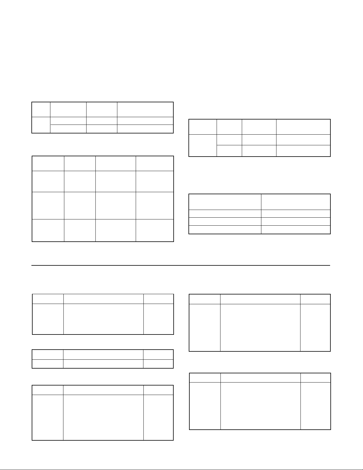
Ordering Information
The following information is provided to order a XL positioner or to adapt an existing positioner from one application
to another.
Linear Actuators
When ordering a positioner for a linear actuator, select
two part numbers; one each from Tables II and III.
Table II: Positioner Model with 3-15 psi or
4-20 mA span for Linear Actuators
Air P/P NT 3000-10 I/P
Action Module Module
Std.
Stroke
(1) The cam can be turned over in the field for opposite air action.
Air-to-Open 10076820 10122958
Air-to-Close 10076821 10122959
(1)
Table III: Linear Actuator Follower Arms
Actuator Stroke Spud Follower
Size (inch) (inch) Arm Kit
1
/4** 2.00 10043879*
25
50
100 / 200
*Requires the use of stem clamp number 55679
** Use short stroke positioner
3
/8** 2.00 10043879*
1
/2** 2.00 10037613*
1
/4 - 11/2** 2.00 10037613
3
/4 - 11/2** 2.00 10037613
3
/4 - 21/2** 2.62 10044111
3** 2.62 10037614
3
/4 - 3** 2.62 - 2.88 10037614
3
/4 - 4** 3.38 - 4.75 10037615
5 - 8** 3.38 - 4.75 10037616
Rotary Actuators
When ordering a positioner for a rotary actuator, select
two part numbers; one from Table IV and one from
Table V which includes part numbers for follower arm.
Table IV: Positioner Model with 3-15 psi
or 4-20 mA span for for Valdisk, Valdisk
150, and ShearStream Rotary Actuators.
Actuator Installed Pneumatic NT 3000-10 I/P
Size Cam
25 B 10075141 10121777
50
100 C 10075142 10121780
(2) The cam can be turned over in the field to the opposite side ‘B’
or ‘C’. To select the correct positioner model choose either ‘B’ or
‘C’ from Table I
(2)
Module Module
Table V: Follower Arms for Rotary Actuators
Actuator Size Follower Arm
(Square-inches) Part Number
25 10034715
50 10034714
100 / 200 10033767
When installed on a rotary valve, the signal vs. CV relationship can be equal percentage or linear, based on air
action as well as cam characteristics. (See Table I.)
Spare Part Kits
Cover Kit – Part No. 10094522
Item No. Description Quantity
2 Cover 1
3 Screw 2
4 O-ring 2
5 Sticker 1
Gauge Kit – Part No. 10129690
Item No. Description Quantity
6 Pressure gauge 0-160 psi 2
Span & Zero Arm Kit – Part No. 10094523
Item No. Description Quantity
40 Range arm assembly 1
43 Pivot bushing 1
44 Pivot Screw 1
45 Snap Ring 2
46 Zero Adjust arm 1
106 Washer 1
Feedback Spring Kit – Part No. 10094524
Item No. Description Quantity
47 Feedback Spring 1
assembly (Includes item
no. 103, 104)
48 Pivot block 1
49 Adjustment knob 1
50 Lock knob 1
Base Kit – Part No. 10094525
Item No. Description Quantity
58 Base 1
63 Screen 1
64 Screen retainer 1
65 Bearing 2
66 Post 2
67 Gasket 1
45-14
Flowserve Corporation, Valtek Control Products, Tel. USA 801 489 8611
Page 15

Standard O-ring Kit – Part No. 10094526
Standard Relay Kit – Part No. 10094530
Item No. Description Quantity
8 Relay/ base O-ring and 6
relay tube O-ring
11 Orifice screw O-ring 1
12 Relay/ base O-ring 2
30 Relay retainer O-ring 2
37 Adjustable seat O-ring 1
38 Adjustable screw O-ring 1
57 Orifice face O-ring 1
69 Input signal O-ring 2
Ext. Temp. O-ring Kit – Part No. 10094527
Item No. Description Quantity
8 Relay/base O-ring and 6
relay tube O-ring
11 Orifice screw O-ring 1
12 Relay/base O-ring 2
30 Relay retainer O-ring 2
37 Adjustable seat O-ring 1
38 Adjustable screw O-ring 1
57 Orifice face O-ring 1
69 Input signal O-ring 2
Item No. Description Quantity
AA Pilot Relay assembly 1
(Includes item no. 7-39,
56, 57, 110)
Ext. Temp. Relay Kit – Part No. 10094531
Item No. Description Quantity
AA Pilot Relay assembly 1
(Includes item no. 7-39,
56, 57, 110)
Std. Linear Cam Kit – Part No. 10094532
Item No. Description Quantity
32 Pan head screw 1
51 Return spring 1
52 Cam shaft 1
53 Cam 1
54 Lock washer 2
55 Nut 2
Std. Rotary Cam Kit – Part No. 10094533
Standard Dia. Kit – Part No. 10094528
Item No. Description Quantity
13 Relay diaphragm 1
16 Signal diaphragm assembly 1
Ext. Temp. Dia. Kit – Part No. 10094529
Item No. Description Quantity
13 Relay diaphragm 1
16 Signal diaphragm assembly 1
Item No. Description Quantity
32 Pan head screw 1
51 Return spring 1
52 Cam shaft 1
53 Cam 1
54 Lock Washer 1
55 Nut 1
108 Cam shaft nut 1
109 Cap 1
Rotary MaxFlo Cam Kit – Part No. 10094534
Item No. Description Quantity
32 Pan head screw 1
51 Return spring 1
52 Cam shaft 1
53 Cam 1
54 Lock washer 1
55 Nut 1
108 Cam shaft nut 1
109 Cap 1
Flowserve Corporation, Valtek Control Products, Tel. USA 801 489 8611
45-15
Page 16

Flowserve Corporation has established industry leadership in the design and manufacture of its products. When properly selected, this
Flowserve product is designed to perform its intended function safely during its useful life. However, the purchaser or user of Flowserve
products should be aware that Flowserve products might be used in numerous applications under a wide variety of industrial service
conditions. Although Flowserve can (and often does) provide general guidelines, it cannot provide specific data and warnings for all
possible applications. The purchaser/user must therefore assume the ultimate responsibility for the proper sizing and selection, installation, operation and maintenance of Flowserve products. The purchaser/user should read and understand the Installation Operation
Maintenance (IOM) instructions included with the product, and train its employees and contractors in the safe use of Flowserve products
in connection with the specific application.
While the information and specifications presented in this literature are believed to be accurate, they are supplied for informative purposes
only and should not be considered certified or as a guarantee of satisfactory results by reliance thereon. Nothing contained herein is to
be construed as a warranty or guarantee, express or implied, regarding any matter with respect to this product. Because Flowserve is
continually improving and upgrading its product design, the specifications, dimensions and information contained herein are subject to
change without notice. Should any question arise concerning these provisions, the purchaser/user should contact Flowserve Corporation
at any of its worldwide operations or offices.
For more information, contact:
Flowserve and Valtek are registered trademarks of Flowserve Corporation.
contact www.flowserve.com or call USA 972 443 6500
Regional Headquarters
1350 N. Mt. Springs Prkwy.
Springville, UT 84663
Phone 801 489 8611
Facsimile 801 489 3719
12 Tuas Avenue 20
Republic of Signapore 638824
Phone (65) 862 3332
Facsimile (65) 862 4940
12, av. du Québec, B.P. 645
91965, Courtaboeuf Cedex, France
Phone (33 1) 60 92 32 51
Facsimile (33 1) 60 92 32 99
Quick Response Centers
5114 Railroad Street
Deer Park, TX 77536 USA
Phone 281 479 9500
Facsimile 281 479 8511
104 Chelsea Parkway
Boothwyn, PA 19061 USA
Phone 610 497 8600
Facsimile 610 497 6680
1300 Parkway View Drive
Pittsburgh, PA 15205 USA
Phone 412 787 8803
Facsimile 412 787 1944
FCD VLAIM045-04 ©2000 Flowserve Corporation. Flowserve Corporation, Valtek Control Products, Tel. USA 801 489 8611
For more information about Flowserve and its products,
 Loading...