

Page 1

Edward Valves
Maintenance Manual for
Edward Pressure-Seal Valves
V-377 R4
Page 2

2
Flow Control Division
Edward Valves
Key to Illustrations...........................................3
Pressure-Seal Valve Figure Numbers..................3
Introduction ....................................................3
Description of Pressure-Seal
Valve Bonnet Types
(Illustration, description and figure numbers)
Type I.........................................................4
Type II ........................................................5
Type III........................................................6
Type IV.......................................................7
Service Problems
Packing Chamber Leak.................................8
Packing Recommendations............................8
Pressure-Seal Gasket Leaks..........................10
Pressure-Seal Leak......................................10
Seat and Disk Joint Leaks............................10
Body Wall Leaks........................................12
Objectionable Vibration, Noise or
Excessive Pressure Drop..............................12
Valve Lubrication........................................12
Repair Procedures
Valve Body Repairs ....................................13
Body Bore Gasket Seal Area Repair.........13
Body Bore Guide Rib Repair ...................13
Seat and Disk Repair ..............................14
Body Wall Repair...................................15
Valve Component Repair ............................15
Disk-Piston Assembly Repair.....................15
Bonnet or Cover Repair ...........................16
Welding Rod Recommendations...................16
Field Repair Equipment...............................17
Disassembly Procedures for
Pressure-Seal Valves
Introduction...............................................18
First Determine the Area of Failure...............18
Disassembly Procedures for
Impactor Handles and Handwheels
Non-Ball Bearing Impactor
Handles and Handwheels........................20
Ball Bearing Impactor Handwheels...........21
Procedures for Removing Limitorque
Operators from Valve Yokes
Revolving Stem Valves or Non-Revolving
Stem Valves with Torque-Only Units...........22
Non-Revolving Stem Valves with
Torque and Thrust Units...........................23
Procedures for Setting Actuator Torque
and Limit Switches
Limitorque Limit Switch and
Torque Switch Setting Procedures .............24
Geared Limit Switch ............................24
Torque Switch .....................................25
Single Torque Switch ...........................25
Double Torque Switch..........................25
Torque Switch Setting...........................26
Disassembly Procedures for Yoke Assemblies
Revolving Stem Valves
with Type I Bonnets.................................27
Revolving Stem Valves
with Type II Bonnets................................28
Non-Revolving Stem Valves
with Type II or III Bonnets.........................28
Valves with Type IV Bonnets.....................28
Procedures for Removing Operator
and Yoke Assembly as a Unit
Revolving Stem Valves
with Type I Bonnets.................................29
Revolving Stem Valves
with Type II Bonnets................................29
Non-Revolving Stem Valves
with Type II, III or IV Bonnets....................30
Disassembly Procedures for
Bonnet Types
Type I Pressure-Seal Bonnets
– Stop and Stop-Check
(Non-Return) Valves..............................31
– Piston-Lift Check Valves.........................32
Type II Pressure-Seal Bonnets
– Stop and Stop-Check (Non-Return)
Valves with Revolving Stems..................33
– Stop and Stop-Check (Non-Return)
Valves with Non-Revolving Stems...........34
Type III Pressure-Seal Bonnets
– Stop and Stop-Check
(Non-Return) Valves..............................36
– Piston- Lift Check Valves........................37
– Tilting Disk Check Valves ......................38
Type IV Pressure-Seal Bonnets
– Stop and Stop-Check
(Non-Return) Valves..............................39
– Piston-Lift Check Valves.........................41
Assembly of Composite Pressure-
Seal Gaskets.................................................42
Reassembly Procedures
for Metal Pressure-Seal Valves
Introduction...................................................43
Type I Pressure-Seal Bonnets
– Stop and Stop-Check
(Non-Return) Valves..............................44
– Piston-Lift Check Valves.........................45
Type II Pressure-Seal Bonnets
– Stop and Stop-Check (Non-Return)
Valves with Revolving Stems..................45
– Stop and Stop-Check (Non-Return)
Valves with Non-Revolving Stems...........45
Type III Pressure-Seal Bonnets
– Stop and Stop-Check
(Non-Return) Valves..............................46
– Piston-Lift Check Valves.........................46
– Tilting Disk Check Valves ......................47
Type IV Pressure-Seal Bonnets
– Stop and Stop-Check
(Non-Return) Valves..............................47
– Piston-Lift Check Valves.........................47
General Information.......................................48
Supplementary Repair Information.......back cover
Ordering Parts...................................back cover
Table of Contents
Page 3

3
Flow Control Division
Edward Valves
Table of Contents (continued)
Illus No.Title Page
I Pressure-Seal Bonnet Type I......................4
2 Pressure-Seal Bonnet Type II.....................5
3 Pressure-Seal Bonnet Type III ....................6
4 Pressure-Seal Bonnet Type IV....................7
5 Typical Globe Valve Nomenclature.........11
6 Pressure-Seal Bonnet Seal Angle.............16
7 Portable Lapping Tool for
Large Valves ........................................17
8 Van Norman Portable
Grinding Machine................................17
9 Van Norman Portable
Boring Machine ...................................17
10 Impactor Handwheel
Non-Ball Bearing Types .........................20
11 Impactor Handwheel
Non-Ball Bearing Types .........................20
12 Impactor Handwheel
Non-Ball Bearing Types .........................20
13 Impactor Handwheel
Ball Bearing Type (with Impactogear)......21
14 Torque-only Limitorque Operator on
Revolving Stem Valve (SMA or SMB) ......22
Illus No.Title Page
15 Torque-only Limitorque Operator on
Revolving Stem Valve (SMB-4T or 5T)......22
16 Torque-only Limitorque Operator on
Non-Revolving Stem Valve.....................22
17 Torque and Thrust Limitorque Operator
on Non-Revolving Stem Valve ................23
18 Limitorque Geared Limit Switch Assy.......24
19 Single & Double Torque
Switch Assemblies ................................25
20 Type I Bonnet on Stop-Check Valve.........27
21 Type I Bonnet on Piston-Lift Check Valve..29
22 Type II Bonnet on Revolving
Stem Stop Valve...................................30
23 Type II Bonnet on Non-Revolving
Stem Stop Valve...................................31
24 Type III Bonnet on Stop Valve.................34
25 Type III Bonnet on Piston-Lift
Check Valve ........................................35
26 Type III Bonnet on Tilting
Disk Check Valve..................................38
27 Type IV Bonnet on Stop-Check Valve.......39
28 Type IV Bonnet on Piston-Lift
Check Valve ........................................41
Key to Illustrations
Introduction
This manual has been prepared to
serve as a guide for the maintenance
of Edward valves of the pressure-seal
bonnet joint construction. It is
designed to help you obtain the most
satisfactory ser vice from these valves.
Although rigid metallurgical, radiographic, physical, and visual inspection is the standard procedure for all
Edward products, it is inevitable that
some valves, after a period of time,
may occasionally require repair.
When this happens, this manual will
assist you so that your valve may be
satisfactorily restored to good working condition with a minimum of time
and expense.
Scope
Before starting, it will be helpful to
have some understanding of the
valve’s physical construction. Consequently, the four basic types of
pressure-seal constructions are discussed and illustrated first. All Edward
pressure-seal valves employ one of
these four basic types, or a minor
modification thereof. Non-pressureseal, or bolted bonnet type valves,
are not included in this manual.
The next major section of this manual
discusses the more common service
problems and failures. It identifies the
problem and explains the reasons for
certain failures. The reason should
be understood before work is
actually started.
602Y
606
606Y
607
607Y
614Y
616
616Y
617
617Y
692Y
694
694Y
695
695Y
702Y
714Y
792Y
970Y
1570Y
1602Y
1614Y
1692Y
1802Y
1814Y
1892Y
2002Y
2006Y
2007Y
2014Y
2016Y
2017Y
2070Y
2092Y
2094Y
2095Y
2570Y
3902Y
3906
3906Y
3907
3907Y
3914Y
3916
3916Y
3917
3917Y
3948Y
3992Y
3994
3994Y
3995
3995Y
4002Y
4006
4006Y
4007
4007Y
4014Y
4016
4016Y
4017
4017Y
4092Y
4094
4094Y
4095
4095Y
4302Y
4306Y
4307Y
4314Y
4316Y
4317Y
4370Y
4392Y
4394Y
4395Y
4402Y
4406Y
4407Y
4414Y
4416Y
4417Y
4448Y
4470Y
4492Y
4494Y
4495Y
4502Y
4514Y
4570Y
4592Y
7502Y
7506
7506Y
7507
7507Y
7514Y
7516
7516Y
7517
7517Y
7548Y
7592Y
7594
7594Y
7595
7595Y
Pressure-seal Valve Figure Numbers
Page 4
4
Flow Control Division
Edward Valves
The procedure to be followed in making
the repair is then explained. This includes
normal valve maintenance as well as major
valve repair. Field repair equipment, available from Edward, is described and
illustrated. Valve lubrication and welding
rod recommendations are also made.
These procedures are adequate for almost
any pressure-seal valve repair or maintenance problem that may arise in the field.
Following is the section describing the
disassembly procedure for the various
valve components; for example, manual of
Limitorque operators, valve yokes, and the
four basic bonnet types. It is very impor-
tant that the Introduction and the paragraphs titled “First Determine the Area of
Failure” be read and understood before
any disassembly work is begun. Several
procedures are described, depending upon
the area of failure. Considerable time can
often be saved by first selecting the proper
disassembly procedure.
The last major section explains how the
various valve constructions are to be
reassembled. Information on how to
contact Edward for additional advice, if
required, and how to order parts is
included.
Description of
Pressure-Seal Valve Types
Edward pressure-seal valves are built with
four basic bonnet arrangements to provide
the most suitable designs for the wide
range of sizes and pressure classes
offered.
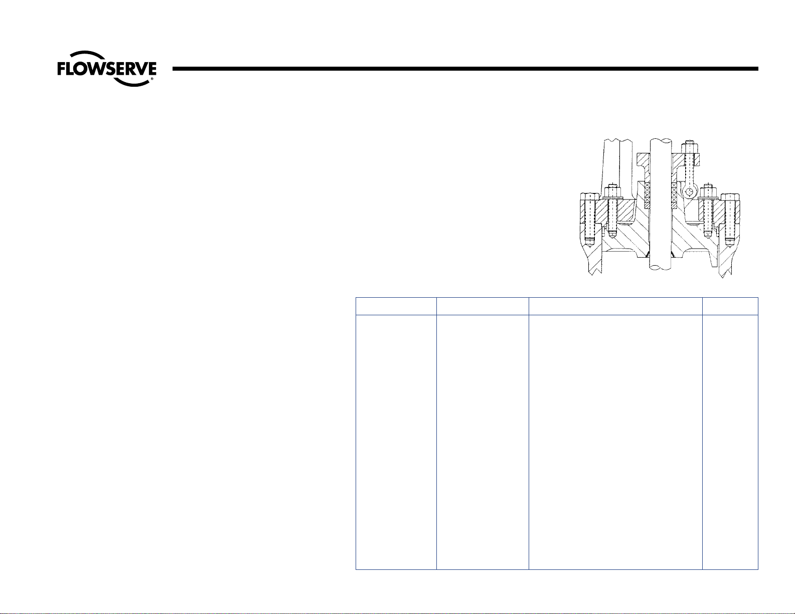
Type I is the studded bonnet design as
shown. It uses the basic pull-up construction
with studs in the bonnet projecting through
the retainer for tightening by use of nuts. It
is a simplified design employed in moderate pressure applications and certain valve
sizes, as shown in the following table.
Description of Pressure-Seal Bonnet Types – Type I
Type I
Illustration No. 1
Pressure-Seal Bonnet
Fig. No. Pressure Rating Type of Valve Size
602Y 600 Flite-Flow Globe Stop-Check (Y-Type) 6-20
606 and 606Y 600 Globe Stop-Check 8-14
607 and 607Y 600 Angle Stop-Check 8-14
614Y 600 Flite-Flow Globe Stop (Y-Type) 6-20
616 and 616Y 600 Globe Stop 8-14
617 and 617Y 600 Angle Stop 8-14
692Y 600 Flite-Flow Check (Y-Type) 16-20
694 and 694Y 600 Horizontal Check 8-14
695 and 695Y 600 Angle Check 8-14
702Y 600-SPL Flite-Flow Globe Stop-Check (Y-Type) 16-20
714Y 600-SPL Flite-Flow Globe Stop (Y-Type) 6-20
792Y 600-SPL Flite-Flow Check (Y-Type) 16-20
1602Y Special Flite-Flow Globe Stop-Check (Y-Type) 16-20
1614Y Special Flite-Flow Check Stop (Y-Type) 16-20
1692Y Special Flite-Flow Check (Y-Type) 16-20
1802Y Special Flite-Flow Globe Stop-Check (Y-Type) 16-20
1814Y Special Flite-Flow Globe Stop (Y-Type) 16-20
1892Y Special Flite-Flow Check (Y-Type) 16-20
Type I
Page 5
5
Flow Control Division
Edward Valves
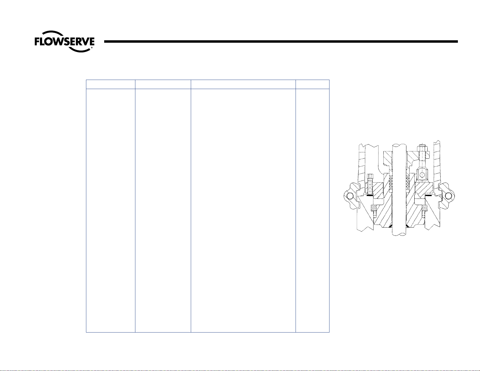
Description of Pressure-Seal Bonnet Types – Type II
Type II
Illustration No. 2
Pressure-Seal Bonnet
Fig. No. Pressure Rating Type of Valve Size
2002Y 1500-SPL Flite-Flow Globe Stop-Check (Y-Type) 3 – 4
2006Y 1500-SPL Globe Stop-Check 2-1/2 – 4
2007Y 1500-SPL Angle Stop-Check 2-1/2 – 4
2014Y 1500-SPL Flite-Flow Globe Stop (Y-Type) 3 – 4
2016Y 1500-SPL Globe Stop 2-1/2 – 4
2017Y 1500-SPL Angle Stop 2-1/2 – 4
3902Y 2500 Flite-Flow Globe Stop-Check (Y-Type) 3-24
3906 and 3906Y 2500 Globe Stop-Check 2-1/2 – 12
3907 and 3907Y 2500 Angle Stop-Check 2-1/2 – 22
3914Y 2500 Flite-Flow Globe Stop (Y-Type) 3-24
3916 and 3916Y 2500 Globe Stop-Check 2-1/2 – 12
3917 and 3917Y 2500 Angle Stop-Check 2-1/2 – 22
3948Y 2500 Elbow Down Stop-Check 10-16
4002Y 900 Flite-Flow Globe Stop (Y-Type) 3 – 4
4006 and 4006Y 900 Globe Stop-Check 2-1/2 – 4
4007 and 4007Y 900 Angle Stop-Check 2-1/2 – 4
4014Y 900 Flite-Flow Globe Stop (Y-Type) 3 – 4
4016 and 4016Y 900 Globe Stop 2-1/2 – 4
4017 and 4017Y 900 Angle Stop 2-1/2 – 4
4302Y 900-SPL Flite-Flow Globe Stop-Check (Y-Type) 3 – 4
4306Y 900-SPL Globe Stop-Check 2-1/2 – 4
4307Y 900-SPL Angle Stop-Check 2-1/2 – 4
4314Y 900-SPL Flite-Flow Globe Stop (Y-Type) 3 – 4
4316Y 900-SPL Globe Stop 2-1/2 – 4
4317Y 900-SPL Angle Stop 2-1/2 – 4
4402Y 2500-SPL Flite-Flow Globe Stop-Check (Y-Type) 3-24
4406Y 2500-SPL Globe Stop-Check 2-1/2 – 12
4407Y 2500-SPL Angle Stop-Check 2-1/2 – 22
4414Y 2500-SPL Flite-Flow Globe Stop (Y-Type) 3-24
4416Y 2500-SPL Globe Stop 2-1/2 – 12
4417Y 2500-SPL Angle Stop 2-1/2 – 22
4448Y 2500-SPL Elbow Down Stop-Check 10-16
4502Y 4500 Flite-Flow Globe Stop-Check (Y-Type) 8-10
4514Y 4500 Flite-Flow Stop (Y-Type) 8-10
4592Y 4500 Flite-Flow Check (Y-Type) 8-10
7502Y 1500 Flite-Flow Globe Stop-Check (Y-Type) 3 – 4
7506 and 7506Y 1500 Globe Stop-Check 2-1/2 – 4
7507 and 7507Y 1500 Angle Stop-Check 2-1/2 – 4
7514Y 1500 Flite-Flow Globe Stop (Y-Type) 3 – 4
7516 and 7516Y 1500 Globe Stop 2-1/2 – 4
7517 and 7517Y 1500 Angle Stop 2-1/2 – 4
Type II
Type II is the push-up design in which the
bonnet retainer ring is screwed onto the
bonnet, and cap screws develop the
upward force. This design is employed on
both intermediate and high-pressure applications. A three-piece construction is used
for the pressure-seal parts.
Page 6
6
Flow Control Division
Edward Valves
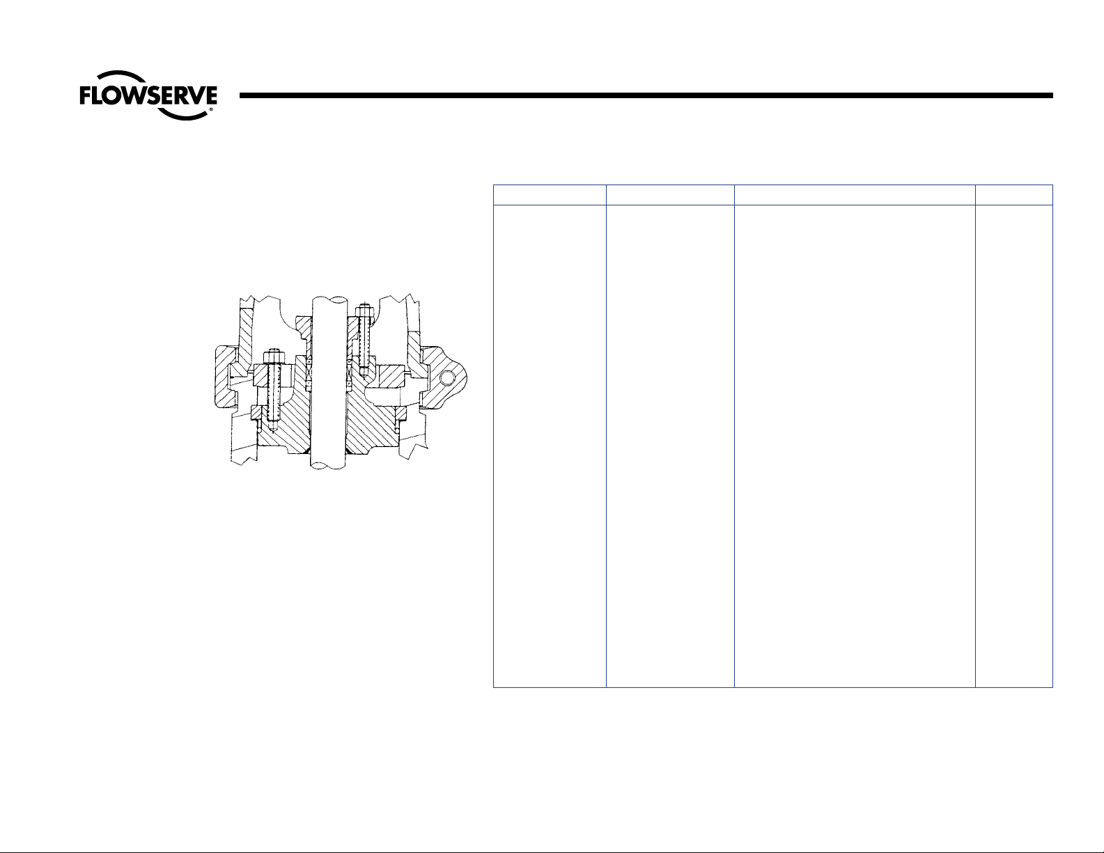
Type III also uses the three-piece pressureseal construction but combines it with the
basic pull-up bonnet. This design is utilized
extensively in the larger valves.
Description of Pressure-Seal Bonnet Types – Type III
Type III
Illustration No. 3
Pressure-Seal Bonnet
Fig. No. Pressure Rating Type of Valve Size
602Y 600 Flite-Flow Stop-Check (Y-Type) 24-32
607Y 600 Angle Stop-Check 24-30
614Y 600 Flite-Flow Globe Stop (Y-Type) 24-32
617Y 600 Angle Stop 24-30
692Y 600 Flite-Flow Check (Y-Type) 24-32
695Y 600 Angle Check 24-30
702Y 600-SPL Flite-Flow Globe Stop-Check (Y-Type) 24-32
714Y 600-SPL Flite-Flow Globe Stop (Y-Type) 24-32
792Y 600-SPL Flite-Flow Check (Y-Type) 24-32
970Y 900 Tilting Disk Check 2-1/2 – 24
1570Y 1500 Tilting Disk Check 3-24
1602Y Special Flite-Flow Globe Stop-Check (Y-Type) 24-32
1614Y Special Flite-Flow Globe Stop (Y-Type) 24-32
1692Y Special Flite-Flow Check (Y-Type) 24-32
1802Y Special Flite-Flow Globe Stop-Check (Y-Type) 24-32
1814Y Special Flite-Flow Globe Stop (Y-Type) 24-32
1892Y Special Flite-Flow Check (Y-Type) 24-32
2002Y 1500-SPL Flite-Flow Globe Stop-Check (Y-Type) 6-18
2006Y 1500-SPL Globe Stop-Check 5-14
2007Y 1500-SPL Angle Stop-Check 5-24
2014Y 1500-SPL Flite-Flow Globe 6-18
2016Y 1500-SPL Globe Stop 5-14
2017Y 1500-SPL Angle Stop 5-24
2070Y 1500-SPL Tilting Disk Check 3-24
2092Y 1500-SPL Flite-Flow Check (Y-Type) 3-18
2094Y 1500-SPL Horizontal Check 2-1/2 – 14
2095Y 1500-SPL Angle Check 2-1/2 – 24
2570Y 2500 Tilting Disk Check 3-24
3992Y 2500 Flite-Flow Check (Y-Type) 3-24
3994 and 3994Y 2500 Horizontal Check 2-1/2 – 12
3995 and 3995Y 2500 Angle Check 2-1/2 – 24
4006 and 4006Y 900 Globe Stop-Check 5-14
4007 and 4007Y 900 Angle Stop-Check 5-24
4014Y 900 Flite-Flow Stop (Y-Type) 6-16
4016 and 4016Y 900 Globe Stop 5-14
Type III
Page 7

7
Flow Control Division
Edward Valves
Description of Pressure-Seal Bonnet Types – Type III and Type IV
Fig. No. Pressure Rating Type of Valve Size
4017 and 4017Y 900 Angle Stop 5-24
4092Y 900 Flite-Flow Check (Y-Type) 3-16
4094 and 4094Y 900 Horizontal Check 2-1/2 – 14
4095 and 4095Y 900 Angle Check 2-1/2 – 24
4302Y 900-SPL Flite-Flow Globe Stop-Check (Y-Type) 5-16
4306Y 900-SPL Globe Stop-Check 5-14
4307Y 900-SPL Angle Stop-Check 5-24
4316Y 900-SPL Globe Stop 5-14
4317Y 900-SPL Angle Stop 5-24
4392Y 900-SPL Flite-Flow Check (Y-Type) 3-16
4370Y 900-SPL Tilting Disk Check 2-1/2 – 20
4394Y 900-SPL Horizontal Check 2-1/2 – 14
4395Y 900-SPL Angle Check 2-1/2 – 24
4470Y 2500-SPL Tilting Disk Check 3-24
4492Y 2500-SPL Flite-Flow Check (Y-Type) 3-24
4494Y 2500-SPL Horizontal Check 2-1/2 – 12
4495Y 2500-SPL Angle Check 2-1/2 – 24
4570Y 4500 Tilting Disk Check 6-10
7502Y 1500 Flite-Flow Globe Stop-Check (Y-Type) 6-18
7506 and 7506Y 1500 Globe Stop-Check 5-14
7507 and 7507Y 1500 Angle Stop-Check 5-24
7514Y 1500 Flite-Flow Globe Stop (Y-Type) 6-18
7516 and 7516Y 1500 Globe Stop 5-14
7517 and 7517Y 1500 Angle Stop 5-24
7548Y Special Elbow Down Stop-Check 10-18
7592Y 1500 Flite-Flow Check (Y-Type) 3-18
7594 and 7594Y 1500 Horizontal Check 2-1/2 – 14
7595 and 7595Y 1500 Angle Check 2-1/2 – 24
7598Y Special Elbow Down Check 10-18
Fig. No. Pressure Rating Type of Valve Size
4502Y 4500 Flite-Flow Globe Stop-Check (Y-Type) 4-6
4514Y 4500 Flite-Flow Globe Stop (Y-Type) 4-6
4592Y 4500 Flite-Flow Check (Y-Type) 4-6
Type IV design used in the 4500 lb. valve
is unique in that the gasket retainer segments are located below the bonnet. The
pressure-seal force is derived by pulling the
bonnet retainer down.
Type IV
Illustration No. 4
Pressure-Seal Bonnet
Type III (continued)
Type IV
Page 8

8
Flow Control Division
Edward Valves
Packing Chamber Leak
Where moisture appears or actual dripping
occurs at the packing chamber around the
stem, gland or gland flange, which cannot
be eliminated by retorqueing the gland bolt,
the following points should be considered.
1. The packing may have become hard.
Replace the packing.
2. Gland travel has been fully taken up.
Repack with new packing.
3. The wrong packing is being used.
See packing recommendations shown
on this page.
4. A stem should be replaced when it
has become deeply scratched,
burred,or otherwise mutilated from
careless handling, or where the stem
has worn, tapered or has been bent.
5. The gaps in the rings of split packing
have not been staggered around the
stem. They should be inserted in this
manner.
6. The packing gland may be binding
against the packing chamber or stem
and does not compress the packing
properly. Make certain the gland fits
the packing chamber and is tightened down equally on each side.
Packing Recommendations
Edward valves are packed with all-purpose
packing sets.This is a combination of packing using braided rings at the top and bottom of the packing chamber and flexible
graphite packing in the center section.
Packing glands should be tightened down
enough to prevent leakage but not enough
to develop excessive operating torque.
When the gland has advanced approximately half way into the packing chamber,
it is recommended that additional packing
rings be added. To obtain best results, the
stem should be thoroughly cleaned.
Replacement packing should be the same
as that originally furnished.
We recommend that replacement packing
be purchased from Edward Valves to
assure packing with the proper density and
corrosion inhibitors are always used.
Important:
Long service life from modern graphitic
packing requires that adequate preloads
be applied when repacking.
1. All parts should be clean and not
scored or pitted, especially the stem.
2. The valve internal parts and bonnet
should be assembled prior to
installing the packing.
3. Position split packing rings with the
ends of adjacent rings rotated 90°.
4. Install in the following sequence:
Bottom Ring – Braided Ring
Center Rings – Die formed
expanded graphite
Top Ring – Braided Ring
5. Clean and lubricate the gland eyebolts.
6. Carefully seat each individual packing ring before adding the next ring.
7. Apply the recommended torque to the
gland nuts evenly without cocking the
gland. See Table A for recommended
torques.
8. Tighten the nuts to the initial values
shown, then loosen and retighten to
the final torque.
9. Stroke the valve, then recheck the
gland nut torques.
NOTE: The torque values given are for
sealing full-rated pressure. For line pressures less than the full CWP rating of the
valve, the final torques may be reduced by
the ratio of P
actual
/CWP down to a mini-
mum of P
actual
= 1500 psig. This will
reduce packing drag and extend packing
life.
Service Problems
Page 9
9
Flow Control Division
Edward Valves
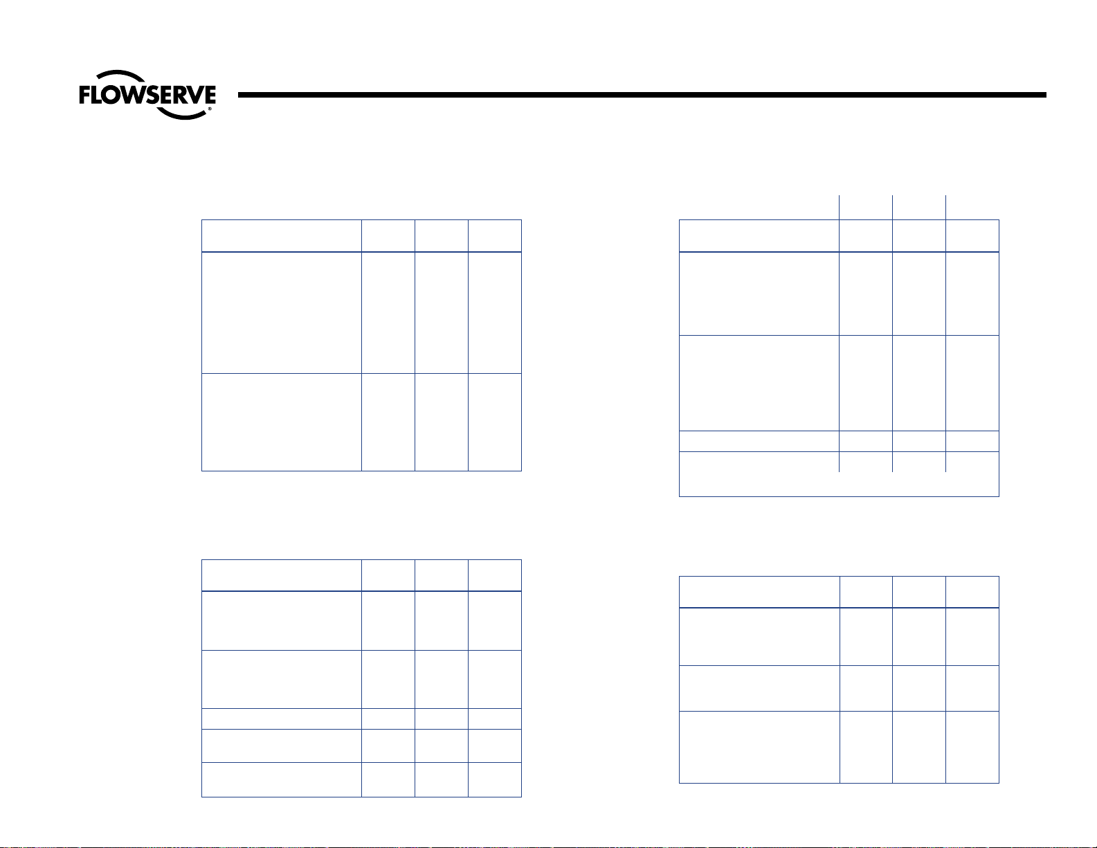
Service Problems (continued)
Initial Final
Figure Numbers Size Torque Torque
2.5 27 8
3278
604, 605, 606, 607 4 41 12
616, 617, 618, 619 5 55 16
704, 705, 706, 707 6 60 17
716, 717, 718, 719 8 89 26
10 143 41
12 209 60
14 233 67
64814
85516
10 62 18
602, 614, 702, 714 12 84 24
14 84 24
16 353 102
20 571 165
Table A
Gland Bolt Torques, ft.-lbs.
Class 600 Valves
Initial Final
Figure Numbers Size Torque Torque
65825
86930
4002, 4014, 4302, 4314 10 115 50
12 185 80
14 185 80
16 206 89
35524
47934
4006, 4007, 4016, 4017 5 84 36
4306, 4307, 4316, 4317 6 89 39
8 143 62
10 199 86
12 252 109
4006, 4016, 4306, 4316 14 266 115
14 252 109
4007, 4017, 4307, 4317 16 331 143
20 633 274
Table A (continued)
Gland Bolt Torques, ft.-lbs.
Class 900 Valves
Initial Final
Figure Numbers Size Torque Torque
7506, 7507, 7516, 7517 2.5 29 21
2006, 2007, 2016, 2017 3 55 40
47857
58461
7502, 7506, 7507, 7514 6 90 65
7516, 7517, 2002, 2006, 8 200 145
2007, 2014, 2016, 2017 10 159 114
12 353 255
7502, 7514 14 353 255
7506, 7507, 7516, 7517 14 378 273
2006, 2007, 2016, 2017
7502, 7507, 7514, 7517 16 672 484
2002, 2007, 2014, 2017 18 672 484
Table A (continued)
Gland Bolt Torques, ft.-lbs.
Class 1500 Valves
Initial Final
Figure Numbers Size Torque Torque
3906, 3507, 3916, 3917 2.5 29 29
4406, 4407, 4416, 4417 3 51 51
460 60
590 90
3902, 3906, 3907, 3914, 6 143 143
3916, 3917, 4402, 4406, 8 267 267
4407, 4414, 4416, 4417 10 286 286
12 473 473
3902, 3907, 3914, 3917 14 479 479
4402, 4407, 4414, 4417 16 479 479
19 269 269
20 269 269
Table A (continued)
Gland Bolt Torques, ft.-lbs.
Class 2500 Valves
Page 10

10
Flow Control Division
Edward Valves
Pressure-Seal Gasket Leak
Edward valves have been produced with
two types of pressure-seal gasket: Earlier
valves had metal gaskets, while later
designs have composite expanded graphite
gaskets. The valves with composite gaskets
can be identified by a “B” prefix on the figure number. Assembly and disassembly of
the two gasket types are essentially the
same except the composite gasket designs
may have belleville spring washers under
the nuts (or capscrews) of the pull-up bolting, and the tightening torque requirements
for the pull-up bolting are different.
To guard against leakage, the bolts should
be kept tightened at all times.
A torque wrench should be used for tightening the bonnet or cover retainer stud nuts or
capscrews, which are used to preload the
pressure-seal gasket.
All nuts/capscrews should be tightened in
an alternating star pattern to ensure even
tightening.
The bolting should be tightened to the
torque values shown in Table B while the
valve is under full line pressure.
Pressure-Seal Leak
Should the leak fail to stop after tightening,
it must be concluded that there is an imperfect pressure-seal, and the valve will have
to be opened for examination. (Note:
Regardless of the cause of failure, opened
pressure-seal bonnets should always be
reassembled with a new gasket. These are
available from stock via Air Express from
Raleigh, North Carolina.) Such a leak may
result from any of the following causes:
1. Incomplete Seal Between Bonnet and
Gasket. An incomplete seal around
the gasket seating surface of the bonnet (or cover on check valves) may be
caused by corrosion, dirt, chips, or
other foreign matter on the mating surfaces of the sealing angle.
2. Incomplete Seal Between Body I.D.
and Gasket. An incomplete seal in
the area of the gasket and body I.D.
contact may be caused by surface
imperfections in the body wall in the
form of pin holes, extended cracks, or
indentations where the metal has
failed sometime after valve installation
and use. Such imperfections may be
surface indications of deeper flaws in
the body casting that may cause a bypass around the pressure-seal.
Seat and Disk Joint Leak
A leak existing between the seat and disk
of a closed valve might be indicated by
one of the following: a definite pressure
loss in the high-pressure side of the valve;
continued flow through an inspection drain
on the low-pressure side; or, in hot water or
steam lines, a downstream pipe that
remains hot beyond the usual length of time
and conductivity range.
Such a leak may be the result of a distorted
seat caused by uneven welding and stressrelieving temperatures that were present in
the body when mounting the valve in the
pipe line. It may also develop because of
the operator’s failure to close the valve
tightly. An increased velocity is imparted to
a flow forced through a very small opening. This increased velocity subsequently
gives rise to the “cutting” of both disk and
seat, particularly by particles of line scale
or rust in suspension or normal solids in
solution; or, in spite of the fact that the stellited hard-facing material on the seat and
disk is corrosion and erosion resistant,
grooves, pit marks, or other surface irregularities may be formed on the seat and disk
joint surfaces when the disk is closed
against a foreign body on the seat. This
sometimes occurs during the initial start-up
of a piping system.
Service Problems (continued)
Table B
Bonnet/Cover Bolt/Nut Pull-Up
Torques
(With Valve Under Pressure)
REQUIRED TORQUE, FT-LBS
BOLT SIZE METAL COMPOSITE
GASKET GASKET
3/8 18 5
7/16 30 5
1/2 45 7
9/16 68 10
5/8 90 15
3/4 150 25
7/8 240 35
1 370 55
1-1/8 533 80
1-1/4 750 110
1-3/8 1020 150
1-1/2 1200 170
1-5/8 1650 230
1-3/4 2250 320
1-7/8 3000 420
2 3300 460
Page 11
11
Flow Control Division
Edward Valves
Leakage of steam through a valve that is
badly steam-cut has a whistling or
sonorous sound. If the valve is only slightly
steam-cut, however, leakage is identified
by subdued gurgling or weak popping
sounds. These sounds can be heard
through a stethoscope or by placing one
end of a stick against the valve body while
holding the other end between the teeth,
with hands over the ears.
To check for a properly closed valve, on
valves with nonrising type handwheels
(non-revolving stem), an indicator is
attached to the lower side of the yoke
bushing that coincides with a pointer
attached to the yoke, when the valve is
tightly closed. This can be viewed through
one of the yoke windows and it represents
the same relative position between the
yoke and yoke bushing, as when the valve
was hydrostatically seat-tested and found
to be tight at the factory. The hydrostatic
pressure is stamped on the indicator. It is
only natural that the indicator will travel
past this mark after repeated closings.
Some operators hesitate to force the valve
crossarm under the handwheel further than
this button, but no harm will be done even
if the indicator travels more than an inch
past the mark when holding a desired
pressure. If a tight seal is not made after
repeated impact blows, it must be concluded that the pressure is bypassing either at
the seat joint or body diaphragm between
the inlet and the outlet passage. Inspection
of the interior of the valve now is advisable.
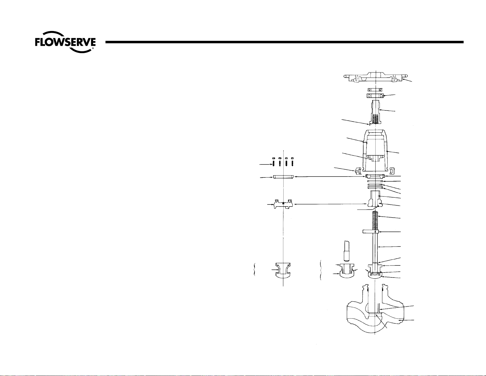
HANDWHEEL–
IMPACTOR TYPE
BEARINGS–USED ON NONREVOLVING STEM VALVES ONLY;
TAPERED AND SPHERICAL ROLLER
BEARINGS ALSO USED
LOCATION OF “INDICATOR” ON
YOKE BUSHING TO INDICATE
WHEN VALVE IS TIGHTLY SEATED
LOCATION OF “POINTER”
ON YOKE TO INDICATE WHEN
VALVE IS TIGHTLY SEATED
ONE-PIECE PACKING GLAND
(OR 2-PIECE GLAND FLANGE
AND GLAND ASSEMBLY)
YOKE LOCK RING
(2 PIECES)
BONNET BACKSEAT
COVER RETAINER
STUDS OR
CAP SCREWS
COVER RETAINER
USED ON
CHECK VALVES
PRESSURE-SEAL
COVER, USED ON
CHECK VALVES
YOKE BUSHING USED ON VALVES
WITH NON-REVOLVING STEMS
(CALLED STEM BUSHING ON
LIMITORQUE OPERATED VALVES)
TYPICAL YOKE–USED ON VALVES
WITH NON-REVOLVING STEMS
(YOKES USED ON OTHER VALVE
TYPES DIFFER)
BONNET RETAINER
SPACER RING
PRESSURE-SEAL GASKET
PACKING CHAMBER
STEM THREADS
STEM GUIDE COLLAR ON
NON-REVOLVING STEMS
STEM
STEM BACKSEAT
DISK NUT
STEM COLLAR
DISK
LOCK
WELD
BODY GUIDE RIBS
(ONLY ONE SHOWN)
SEAT WITH STELLITE
HARD FACING
FOR STOP
CHECK
VALVES
DISK PISTON
ASSEMBLY
PISTON
PISTON
FOR
CHECK
VALVES
DISK
BODY
FOR STOP
VALVES
DISK STEM
ASSEMBLY
TYPICAL PRESSURE-SEAL
BONNET AS USED ON STOP &
STOP-CHECK VALVES
GASKET RETAINER SEGMENTS
(SEVERAL PIECES)
}
Illustration No. 5
Typical Globe Valve Nomenclature
Service Problems (continued)
Page 12

12
Flow Control Division
Edward Valves
Body Wall Leak
This is a visual leak through the body wall,
welding end or end flanges and may be the
result of a shrink cavity or other void in the
casting. If small at first, such a leak may go
unnoticed for a time, particularly if the valve
is heavily insulated and the pipe line at that
point is sufficiently warm to keep the insulation dry enough to escape notice.
Objectionable Vibration, Noise or
Excessive Pressure Drop
Excessive vibration noise or humming coming from within a stop-check, non-return or
check valve indicates the possibility that
the disk-piston assembly is wedged inside
the body. Such sticking may be caused by
uneven body guide rib wear on the downstream side induced by oversizing the
valve, or by corrosion, by flakes of line
scale, or by particles of weld spatter that
may have entered the valve during construction of the piping, and which later
washed up into the piston bearing area of
the body I.D.
On stop-check and non-return valves, the
stem position is indicated by the stem
guide collar on non-revolving stems, or by
the position of the handwheel on revolving
stems; the stem should normally be fully
open against the bonnet backseat in order
that the disk-piston can lift the full amount.
When the disk is not touching the bottom
of the stem or the bottom stop lugs on the
bonnet (due to a wedged disk-piston or
insufficient flow, for example), then the disk
assembly is free to move laterally within
the body. This motion in most cases causes
a slight vibration which can be felt through
the body, yoke and handwheel.
Screwing the stem down slowly to contact
the disk first increases the intensity of vibration to the hand and to the ear, but further
downward, movement of the stem builds
sufficient contact pressure and eliminates
the vibration. This also tends to dislodge
any foreign particles that may have been
the initial cause for disk-piston wedging.
The position of the lift indicator on the
yoke, where vibration ceased, should be
noted and any increase in pressure drop
indicated on available gauges recorded. It
may be that when the stem is screwed
back to the full open position, the disk will
again remain in a floating position, which
could indicate oversizing of the valve for
the flow conditions. It is always recommended that check valve size selection be
governed by flow conditions rather than by
adjacent piping. Oversizing induces vibration or noise and causes excessive, uneven
guide rib wear, giving rise to greater diskpiston assembly clearance on one side of
the body.
By means of other valves in the line, it may
be possible to vary the rate of flow through
a noisy check valve sharply enough (in a
short period of time) to dislodge the piston
from its wedged position.
Valve Lubrication
In order to obtain full service life, valves
require periodic lubrication of the bearings
and stem threads, as does any rotating
machinery.
On valves where the stem bushing and
bearings are in the motor operator, the
bearings are lubricated by the operator
lube supply, which should be maintained
at the recommend level.
Valves that have bearings in the top of the
yoke have lube fittings on the valve yoke
for convenient relubrication.
Stem threads also require periodic replenishment of the lubricant. Exposed threads
should be wiped clean of old grease and
accumulated dirt and fresh lubricant
applied. This can be most effectively done
with the valve in the closed position.
For valves that see frequent operation, the
lubricant should be replenished on bearings and stem threads every three months.
If extreme service conditions dictate, the
plant operating engineer should establish
a more frequent relube schedule.
For valves that are operated infrequently,
relubrication at least once a year is recommended. The recommended lubrication for
both bearings and stem threads is Rykon EP
#2, manufactured by The American Oil
Company. This is an extreme-pressure,
extreme-temperature lubricant of high
quality.
Valves equipped with automatic stem lubricators should be maintained in accordance
with the above instructions for the bearings
and as required to maintain the lube level
in the stem lubricator reservoir.
Service Problems (continued)
Page 13

13
Flow Control Division
Edward Valves
VALVE BODY REPAIRS
Body Bore Gasket Seal Area Repair
with Metal Gasket Only
Pressure-seal valves made prior to 1952
were made with a 47° bonnet seal angle
and the body bore seal was in the parent
metal of the body castings. In 1952 the
design was changed to a 25° seal angle
and the body castings were inlayed with
18-8 stainless at the seal area. When a leak
developed on the older valves, the gasket as
well as the body bore were wire drawn.
If the depth of defects are .010” or less,
the seal area can be honed using a
portable Sunnen Hone. This device is
adjustable for different bore sizes and can
be operated by one man using a portable
electric drill of 1/2“ to 3/4“ capacity.
When the defects are greater than .010”,
welding will be required to cut down the
repair time.
First make visual inspection all around this
area, noting, if possible, where flaws may
occur. Next wash the area with a suitable
solvent, drying with clean rags and, if necessary, polishing with a fine grade of
emery cloth to remove any undesirable
scale or foreign matter that may have been
deposited on the area suspected of having
flaws. Use a dye penetrant test if cracks
are suspected.
Where it is necessary to repair the body
inlay by welding, note the following:
1. Prior to any cutting or welding operations being performed on the valve, it
is necessary that adequate seat joint
protection be provided and some
means of insurance against getting
chips, weld spatter or other foreign
matter into the pipe line if the valve is
permanently mounted. A round piece
of sheet metal placed over the seat
and taped in place will furnish
adequate protection.
2. Chip out the defective area in the
body, being careful to remove the
affected portion to its end, inside
the casting, and to thoroughly clean
it away.
3. With a small hand grinder, grind the
chipped area smooth.
4. Preheat an area large enough
around the imperfection so that during the entire welding operation heat
will be retained at approximately
400°F.
5. Use a stainless steel inlay selected
from either 18-8 stainless steel rod,
Harstain 18-8, Stainlend “K” 18-8,
Stainweld 18-8 or equivalent.
6. Lay the weld in thin, even layers,
peening each layer before proceeding with the next, and being careful
to maintain a temperature above
400°F in the area being repaired.
Peening the bead actually stretches it
and counteracts its tendency to contract and shrink as it cools. The last
layer of weld must overlap onto the
sound metal to ensure a weld without
an undercut at the edges. The overlapping should be done along this
edge by using a welding rod of 1/8”
maximum diameter. The last layer
should bring the height of the welded
area up to 1/16” above the original
surface, as checked with a straight
edge along the body bore.
For this type of weld repair, it is recommended that the last layer be
pounded while still hot with the flat
face of the hammer. Thermal stress
relieving is not recommended.
With a hand grinder, rough grind the
welded surface to within about .010”
of the finished surface. A simple
template cut from thin sheet metal
and having the same arc as the body
bore diameter, and a straight edge
laid along the body bore can be
used as a guide. A final cut then can
be made, using a fixture similar to
the one shown in Illustration No. 9.
Final finishing can be done with the
adjustable Sunnen hone described on
page 17.
After removing all dirt, chips, slag,
spatter, and grinding dust from the
body, the bore should be polished
with fine emery cloth and then thoroughly cleaned before reassembly of
the valve.
It is best that a new pressure-seal gasket be used upon reassembly.
Body Bore Guide Rib Repair
Where more than one guide rib is
involved, each rib should be preheated
and welded before proceeding to the next.
1. Follow steps 1 through 3 of the section titled “Body Bore Gasket Seal
Area Repair” on this page.
Repair Procedures
Page 14

14
Flow Control Division
Edward Valves
2. Heat the body area adjacent to the
guide rib to approximately 200°F.
This can be done locally with an oxyacetylene torch.
3. Select the proper welding rod to suit
the body material (1/8” maximum
size rod is recommended here). See
page 16 for weld rod recommendations. Using the same welding procedure as described for step 6 in the
previous section, build up the guide
rib at least 1/16” above the original
finished surface. The welding should
be started at the bottom so as to create a small shelf, and then proceeded up the guide rib.
If stainless steel inlay is desired on
the guide ribs, use AWS 5.4, E309L
stainless electrodes.
4. Finishing after welding is also similar
to that described in the previous section and in addition, the edges of the
guide ribs should be rounded off
smooth. Check the progress of the
grinding by using a straight edge
and feeler gauges. As the bonnet
bore and guide rib approach alignment a light can be placed on one
side of the straight edge and the high
spots in the guide rib observed on
the other. Where a check valve or
stop-check (non-return) body is being
repaired, the progress of the finishing
cuts can also be measured by slipping some long pieces of shim stock
between the I.D. of the body guide
ribs and the O.D. of the disk-piston
assembly, which has been placed
centrally in position on the seat joint.
A shim should pass around the disk
at all three guide ribs with equal
clearance. The original design clearance is .020 to .030 inches on the
diameter. The disk-piston assembly
should also be moved up and down
to make sure that it is free.
It is recommended that where guide
rib repairs have been made, the seat
and disk joint be checked for distortion and relapped, if necessary.
Seat and Disk Repair
The following description does not apply to
tilting-disk check valves. For repair information on these valves, contact your local
Edward Sales representative.
A valve seat joint will require repairing in
any instance where the seating surface permits a leak because it has been altered
from the original state in which it was
shipped from the factory; where corrosion
has set in to cause pit marks on the seating
surfaces of either the body or disk; where
the seat has become distorted because of
an abnormal heating condition; or, where
a groove has been formed on the seat or
disk by closing the valve against a foreign
body. Verification of such a faulty condition
may be obtained by a seat blueing test or
by careful visual examination.
The stellited seats in these pressure-seal
valves are not easily scored, but where
reconditioning is necessary, the following
points should be observed:
Where an indentation or pit marks on
the valve seat joint are deep (.010 or
greater), a cast iron lap with suitable
lapping compound will speed up
repair. The included angle of the valve
seat is 90° and the cast iron lap should
be closely guided in the body bore during the lapping.
Lap first with the cast iron lap and finish
with the valve disk, which has been
reground or relapped, if necessary. For
initial lapping, use Clover compound
“A.” Norton 320 mixed with olive oil
or sperm oil to a molasses consistency
is also recommended for finish lapping.
For rough lapping, Carborundum H20
coarse is recommended.
In the lapping operation, lap against
the seat with a small quantity of the lapping compound placed between the
mating surfaces. It is important that not
too much pressure be applied on the
lap or disk against the seat. With the
lapping compound in place between
the mating surface, the lap or disk
should be reciprocally rotated as far as
arm movements will permit while standing in one position; the strokes should
be light, and the lap or disk should be
lifted frequently and turned to a new
position circularly around the valve
body so that lapping will be rotated
over a new area. To make cer tain the
pressure strokes are light, it is necessary on large valves to suspend the disk
and stem assembly from a coil spring in
such a manner as to allow the disk to
bear, but lightly, against the seat. See
Figure A on page 17; for another type
see Illustration No. 7.
Repair Procedures (continued)
Page 15

15
Flow Control Division
Edward Valves
For smaller size valves, a driving handle can be easily made of 3/8” diameter wire bent as per Fig. B on page 17.
These small assemblies, being much
lighter, do not require a supporting
spring. Stellited seating faces are hard
and lapping time is variable, depending on the extent of flaws on the surface
and the position of the valve in the line.
If a seat requires machining prior to
lapping, a fixture similar to that shown
in Illustrations 8 and 9 on page 17,
can be used.
The disk of stop valves will also require
refinishing. When the only defects that can
be found on the disk-stem assembly occur
on the seating surface, it becomes very
convenient to push the stem into a lathe
spindle and chuck on the disk nut diameter
without taking the assembly apart. (However, if the stem is too large to fit through the
lathe spindle, it will have to be taken apart
as described in the following paragraph).
Hold the disk using a four jaw chuck so
that the large O.D. and seating surface run
true. Grind the seating surface using a tool
post grinder. Just go deep enough to clean
the surface. Polish the seating surface with
fine emery cloth.
If, when checking the disk-stem assembly,
it is found that the assembly is tight or does
not swivel freely, it will be necessary to
disassemble. Occasionally it is possible to
cut the lock welds with a hack saw and
unscrew the disk from the disk nut. However, it will usually be found expedient to
chuck the disk O.D. in a lathe and cut the
lock welds, including the weld that penetrates the first thread. After this weld metal
has been cleaned away, the disk nut will
readily unscrew. Repair any damaged surfaces on the stem, disk nut, stem collars or
disk. Then proceed to repair the disk seating surface as described above. When finishing the disk in this manner, it will not be
necessary to lap it to the seat.
Body Wall Repair
There are five basic steps in repairing a
casting defect:
1. Cut out to sound metal. Attempting to
weld over the defect will only leave a
notch that may reintroduce the defect.
Cutting may be done by chipping,
grinding or flame gouging. The amount
of metal removed should be held to a
minimum to avoid distortion during subsequent welding.
2. Preheat, using the minimum temperature
specified by the material specification
and/or the design code. Use at least
400F on WC9 or C5 material, 300F on
WC6. Although cast carbon steels such
as WCB or WCC do not require preheat, it may be advantageous to
remove any moisture or other contaminants from the area to be welded. This
may also identify any leak paths. There
are also disadvantages to preheat,
especially localized preheat, that must
be considered when working in areas
of the casting with finish machined
dimensions. Distortion may result in
more damaging problems than those
concerns created by the original defect.
Lower preheats and the control of interpass temperature are two methods used
to minimize distortion.
3. Welding should be done by qualified
welders, using qualified procedures and
weld material of a chemistry matching
the casting (see Table on page 16 for
welding rod recommendations). The
final weld should be blended into the
contour of the casting.
4. Stress relieving is generally recommended. Decisions to not stress-relieve should
factor in piping code rules. The temperatures must be based on material specification and piping code recommendations. Again, since temperatures are
much higher than those experienced in
welding, there are also disadvantages
that must be considered. Distortion may
result in more damaging problems.
Lower temperature post-weld heat treatment is sometimes an option for carbon
steels.
5. The final weld should receive any needed nondestructive testing. This should
include a visual examination and liquid
penetrant or magnetic particle examination. Some major weld repairs could
even mandate radiography to ensure a
sound weld.
VALVE COMPONENT REPAIR
Disk-Piston Assembly Repair
It is possible that the bearing surfaces on
the O.D. of the disk-piston assembly and
I.D. of the body can become scored
deeply enough to cause a binding or
wedging of the piston assembly in a full, or
partially, open or closed position. Such
scores and resulting burrs may be caused
by particles of weld spatter, flakes of hard
Repair Procedures (continued)
Page 16

Flow Control Division
Edward Valves
Repair Procedures (continued)
line scale or other foreign matter that has
inadvertently gotten into the line. Upon disassembly, any body and disk-piston assembly burrs must be removed with emery
cloth, and the bearing surfaces otherwise
made smooth and clean again. Where the
burrs on the piston are very large, it may
be more convenient to chuck the assembly
in an engine lathe and file them off.
Bonnet or Cover Repair
In late 1951 and early 1952 important
changes were made in the pressure-seal gasket design. These changes have greatly
reduced the likelihood of gasket seal leakage. In any case of gasket or bonnet leakage necessitating repair or replacement, it is
strongly recommended that the valve be converted to the new style by replacing the bonnet, or cover, and the pressure-seal gasket.
Where foreign matter of any sort is responsible for a gasket seal leak on the outer
angular sealing surface of the bonnet, it is
very likely that it has caused an impression
in this same sealing surface that must be
removed completely before reassembling.
This can be done by taking a shaving or
skin cut on the sealing surface. In so
doing, it is mandatory that the work be
chucked concentric and square to all existing diameters and surfaces and that the
angle be remachined at 25°, plus 1/2°,
minus 0° as shown in Illustration No. 6.
For old style valves the angle should be
47°, plus 1/2°, minus 0°. When finished,
this surface must be smooth and free from
any marks or surface blemishes, and the
circumferential point where the largest
O.D. meets the angular seal surface must
be lightly honed to remove any sharp
edges or fins.
Welding Rod Recommendations
PRESSURE
SEAL
GASKET
25° +1/2°
–0°
Illustration No. 6
Pressure-Seal Bonnet Seal Angle
Material to be Welded
Weld Rod
Recommendations
ASME IX
Material ASTM Grade AWS Classification
P-Numbers
P-1 Carbon Steel 1. ASTM A216, Grade WCB AWS 5.1
2. ASTM A105 E7018
P-4 1-1/4% Chromium, 1. ASTM A217, Grade WC6 AWS 5.5
1/2% Molybdenum 2. ASTM A182, Grade F11 E8018-B2
Low Alloy Steel
P-5 2-1/4 Chromium, 1. ASTM A217, Grade WC9 AWS 5.5
1% Molybdenum 2. ASTM A182, Grade F22 E9018-B3
Low-Alloy Steel
P-8 18% Chromium, 1. ASTM A351, Grade CF8M AWS 5.4
8% Nickel 2. ASTM A182, Grade F316 E316
Stainless Steel
P-8 18% Chromium, 1. ASTM A351, Grade CF8C AWS 5.4
8% Nickel 2. ASTM A182, Grade F347 E347
Stainless Steel
Welding Edward Valves In-Line
When welding a valve in-line, the installer should apply the specific technical rules imposed by the jurisdictional
authority of the area where the valve is installed. In the absence of such rules, following are suggested practices
for welding Edward Valves in-line:
1. Welding should be done using procedures and personnel qualified in accordance with ASME Section IX. Rules
for preheat and postheat are stated in Chapter V of ASME B31.1 (Power Piping).
2. The valve should be welded in-line, one end at a time, in a closed position (approximately a half-turn after the
seat in the body comes in contact with the disk). This is suggested to preclude warpage between seating surfaces caused by temperature-induced stresses during welding or subsequent heat treat. It also protects the seat
from weld spatter that might coat the lapped seat and disk. When post-weld heat treat is required, each weld
end should be heat-treated one at a time, to minimize impact of heat on valve internals. Do not heat treat an
Edward Valve with a piping attached as a unit in a furnace, as warpage of parts may occur. After welding,
open the valve and flush the line to clean out all foreign matter.
16
Page 17

17
Flow Control Division
Edward Valves
Field Repair Equipment
Available from the Edward Manufacturing
plant in Raleigh, N.C., are some basic
tools for repairing valves in the field. This
equipment was developed for customer use
on a rental basis. Of course, an emphasis
has been placed on large valve repairs
where economics justify extensive repairs
in the field rather than removing the valve
from the pipe line for return to the factory.
Contact your local Edward Valves sales
representative for more information. A list
of this equipment follows:
1. Lapping equipment for all pressureseal valves from 2-1/2 to 18” in all
pressure classes. See Figs. A, B and
Illustration No. 7 on this page.
2. Self-centering, lap-guide fixtures for
lapping valve seats in valves 8” and
up in all pressure classes. See Figs.
C, D on this page. This fixture can be
used when the valve is installed in
any position, and is suggested in
place of (1) above, when the stem is
horizontal or mounted down.
3. Sunnen Portable Hone for honing
pressure-seal bores from 4” to
14-1/2“ diameter. (Not illustrated)
4. Van Norman portable boring
machine for reboring valves in the
field. Grinding attachments are also
available to some sizes for grinding
seat joints. See Illustrations No. 8
and No. 9 on this page.
5. Air-driven portable boring machine
for reboring guide ribs and seats of
valve bodies in the line. (Not
illustrated)
SPRING
GUIDE PLATE
GUIDE PLATE
FRICTION CLAMP
FRICTION CLAMP
SPRING
SPRING
SOFT STEEL
BUSHING
SOFT STEEL
BUSHING
YOKE LOCK
RING
STEEL PILOT
PLATE
STEEL PILOT
PLATE
DISK DRIVER FOR
LAPPING LARGE VALVES
DISK DRIVER FOR
LAPPING SMALL VALVES
SEAT AND DISK LAPPING
FIXTURE FOR VALVES
MOUNTED WITH STEM
DOWN OR HORIZONTAL
(SHOWING VALVE WITH YOKE
LOCK RING CONNECTION
TO BODY)
SEAT AND DISK LAPPING
FIXTURE FOR VALVES
MOUNTED WITH STEM
DOWN OR HORIZONTAL
(SHOWING VALVE WITH
STUDDED YOKE CONNECTION
TO BODY)
Fig. A
Fig. C
Fig. D
Fig. B
Illustration No. 7
Portable Lapping Tool
for Large Valves
Illustration No. 8
Van Norman
Portable
Grinding Machine
Illustration No. 9
Van Norman
Portable
Boring Machine
Page 18

18
Flow Control Division
Edward Valves
Introduction
Step-by-step disassembly procedures are
described for all types of Edward pressureseal bonnet valves, including those with
manual and motor operators. It is impor-
tant that the following paragraphs be read
and understood before any specific
disassembly work is started.
First Determine the Area
of Failure
Failures or maintenance problems, for
other than check valves, can be divided
into three major areas. The area involved
will affect the disassembly procedure to be
followed. These areas, in general, are:
Area 1 The impactor Handwheel or
Handle, or the Limitorque
Operator.
Area 2 The yoke assembly, including the
yoke and yoke bushing, and in
addition on non-revolving stem
valves, the yoke bearings and
stem guide collar.
Area 3 The valve internals, including the
bonnet, body, stem, disk, disk-nut,
gland and seats.
If failure is indicated in Area 1, refer to the
applicable section “Disassembly Procedure
for Impactor Handles” on page 19, or
“Disassembly Procedure for Removing Limitorque Operators from Valve Yokes” on
page 20.
If failure is indicated in Area 2, it will be
necessary to first remove the valve operator. Therefore, refer first to the applicable
operator disassembly procedure described
in the above paragraph. Then proceed to
the section “Disassembly Procedure for
Yoke Assemblies” on page 27, for the
actual disassembly of Area 2.
If failure is indicated in Area 3, two methods are available. In method 1, the operator and yoke assembly may be removed
from the valve body as a unit. This requires
less time but requires adequate clearance
area above the valve. Also, large handwheels, say 48” diameter and above, are
massive and sometimes difficult to handle
when attached to the yoke assembly. For
these reasons, the second method is to first
remove the operator from the yoke, and then
the yoke from the body, in separate steps.
Disassembly Procedures for Pressure-Seal Valves
CAUTION
As a general reminder, make sure all pressure is removed from
valves, both upstream and downstream, before any disassembly
work is started. An exception to this is valves requiring service
only on the operator (Area 1) or Yoke Assembly (Area 2),
where the valve can remain in service. NOTE: Removal of the
yoke assembly under pressure does not apply to revolving stem
valves, only non-revolving. The following stem positions should
be observed:
1. For service in Area 1:
a. If pressure is to be maintained in the valve, back seat to the full
open position. On Limitorque operated valves, only torque-only
operators will permit service in Area 1 under pressure. See
definition of “torque-only” units on page 22.
b. If no pressure is to be maintained in the valve, close the
valve fully and open approximately 1/8”.
2. For service in Area 2:
a. For non-revolving stems only, if pressure is to be main-
tained in the valve, back seat to the full open position.
Never service revolving stem valves in Area 2 while
under pressure.
b. If no pressure is to be maintained in the valve, close the
valve fully and open approximately 1/8”.
3. For service in Area 3:
Close the valve fully and open approximately 1/8”.
Service Area 3 only without pressure in the valve.
Page 19

19
Flow Control Division
Edward Valves
For Method 1, first remove the operator-
yoke assembly combination as described
in “Procedure for Removing Valve Opera-
tor and Yoke Assembly as a Unit” on page
29. Then proceed to the section “Disassembly Procedure of Bonnet Types” on page
31, omitting any steps preceded by an
asterisk (*) for the actual disassembly of
Area 3. On all revolving stem and Type IV
bonnets, only method 2, as follows, should
be used.
For Method 2, first remove the operator by
following the applicable section, “Disas-
sembly Procedure for Impactor Handwheels
and Handles” on page 19, or “Disassembly Procedure for Removing Operators
from Valve Yokes” on page 22. Then, pro-
ceed to the section “Disassembly Procedure
of Bonnet Types” on page 31, for actual
disassembly of Area 3. On Type IV bonnets, reverse this procedure and complete
steps 1 through 9 on pages 39 & 40,
before beginning operator disassembly.
If failures are indicated in any combination
of Areas 1, 2, or 3, then each of the
respective procedures must be followed.
For check valves without stems or operators, simply use the proper section under
“Disassembly Procedure of Bonnet Types”
on page 31.
Disassembly Procedures
for Impactogear Handles
and Handwheels
(With or Without Impactogear
Air Wrench Operators)
AREA 1
Edward pressure-seal valves use several
designs of Impactor handles or handwheels, depending upon the valve size
and pressure class.
Handwheels can be removed while the
valve is pressurized, but caution must be
observed to make certain that it’s first in
the back-seated or fully opened position.
See “Caution” on page 18.
Valves equipped with Impactogear air
wrench operators do not require disassembly of the Impactogear itself. However, during regular impactor handwheel disassembly, the Impactogear pinion gear and the
handwheel gear will be separated.
All of the following handwheel disassembly
procedures are arranged in accordance
with the general comments on page 18.
Study these pages carefully before beginning disassembly.
To disassemble, first determine the type of
handwheel on the valve by measuring its
diameter or referring to the valve dimension drawing. Then select the proper
procedure, as listed below.
Disassembly Procedures for Pressure-Seal Valves (continued)
Page 20

20
Flow Control Division
Edward Valves
Non-Ball Bearing Type Impactor
Handles and Handwheels
All have 12, 14, 16, 20, 26, or 30 inch
diameters. See Illustrations No. 10, 11,
and 12 on this page.
These handwheels are of relatively simple
design and utilize fewer parts than the ball
bearing type. (Not to be confused with ball
bearings in the valve yoke.) Not illustrated,
but of similar construction to Illustration
No. 10 on this page, are Impactor handles. The following instructions apply, in
general, to all non-ball bearing types.
1. Remove the handwheel locknut,
which is the uppermost part on the
top of the valve stem. On some
designs, it is a friction device and is
merely unscrewed. On others, a roll
pin must first be driven out. On
another design, a small lock screw
must be unscrewed.
2. Mark the relative position of the handwheel and cross arm so the original
relationship can be restored when
reassembling. If this is not done, the
handwheel could be reassembled
180° out of the original position.
3. Lift the handwheel off the valve, using
a suitable capacity chain hoist for
large handwheels. If the stem of the
valve is mounted vertically, position
the hoist directly above the handwheel. Otherwise, the hoist should be
positioned slightly away from the
handwheel in line with the stem.
4. Crossarm Removal: For all valves
being serviced in Area I or revolving
stem valves in Area 2, the crossarm
can be removed by tapping lightly
with a hammer on the underside. If
the crossarm is keyed to the yoke
bushing, as in non-revolving stem
valves, the handwheel bushing is first
removed by unscrewing the cap
screws holding the handwheel bushing to the handwheel, and then
unscrewing the handwheel bushing
from the yoke bushing. The keyed
crossarm can now be removed by
tapping the underside with a hammer
and lifting off.
Illustration No. 12
Impactor Handwheel
Non-Ball Bearing Types
Illustration No. 11
Impactor Handwheel
Non-Ball Bearing Types
Illustration No. 10
Impactor Handwheel
Non-Ball Bearing Types
CROSSARM
ROLL PIN
HANDWHEEL LOCKNUT
HANDWHEEL LOCKNUT
ADAPTER (EQUIVALENT
TO CROSSARM
IMPACTOR
HANDWHEEL
IMPACTOR
HANDWHEEL
IMPACTOR HANDWHEEL
VALVE YOKE BEARING
HANDWHEEL LOCK NUT
LOCKSCREW
HANDWHEEL BUSHING
CROSSARM
KEY
Disassembly Procedures for Impactor Handles & Handwheels
Page 21

Flow Control Division
Edward Valves
Disassembly Procedures for Impactor Handles & Handwheels (continued)
BEARING NUT
BALL BEARING
GEAR COVER ASSEMBLY
(VALVE YOKE)
CROSSARM
(VALVE YOKE BUSHING)
(VALVE YOKE BEARING)
SHOWN WITH
IMPACTOGEAR
IMPACTOR
HANDWHEEL
LOCKING
SCREWS
KEY
Ball Bearing Impactor Handwheels
(With or without Impactogears)
All have 28, 36, 48 or 72” diameters. See
Illustration No. 13 on this page.
These impactor handwheels differ in diam-
eter and design from the non-bearing type
in that the handwheel turns on ball bearings. The following instructions apply to all
sizes.
1. Remove the cover plate screws and
the cover plate.
2. Back off all of the locking screws.
3. Mark the relative position of the
handwheel and crossarm so the original relationship can be restored when
reassembling. If this is not done, the
handwheel could be reassembled
180° out of the original position.
4. Provide a suitable capacity chain
hoist, at least 1500 lb., to remove
the handwheel. If the stem of the
valve is mounted vertically, position
the hoist directly above the handwheel. Otherwise the hoist should be
placed slightly away from the handwheel in line with the stem.
a. The handwheel bearing nut and
handwheel are removed as an
assembly.
b. Unscrew the handwheel bearing
nut using a tool to engage the two
drive holes in the top of the nut or
a strap wrench on the O.D. To
prevent the yoke bushing from
turning, hold it with a strap
wrench or other suitable tool.
c. Begin with all slack out of the
hoist, and retain a taut chain by
simultaneously taking up the slack
as the handwheel bearing nut is
fully unscrewed and lifted off the
valve.
5. Crossarm Removal: For all valves
being serviced in Area I or revolving
stem valves in Area 2, the crossarm
can be removed by tapping lightly
with a hammer on the underside until
it is free of the key(s).
6. If malfunction is indicated within the
handwheel bearing, the balls can be
removed by unscrewing the filler hole
set screw, tipping the handwheel so
the hole is down, and ‘fishing’ out
the individual balls. Need for this
should be rare, if ever.
Illustration No. 13
Impactor Handwheel Ball Bearing Type (w/Impactogear)
21
Page 22

22
Flow Control Division
Edward Valves
Edward pressure-seal valves use various
types of Limitorque operators, depending
upon the size and pressure class, which
determines the torque requirements,
whether the stem is revolving or non-revolving, and whether the valve takes the stem
thrust (torque-only unit) or the operator
takes the stem thrust (torque and thrust
unit). The procedures below describe the
removal of these various types from the
valve yoke. Also included are complete
instructions for resetting the torque and
limit switches. Disassembly procedures for
the Limitorque operators themselves are not
included and appropriate instructions
should be obtained before starting.
On torque-only Limitorques, the operator
can be removed while the valve is pressurized, but caution must be observed to
make certain that the valve is first in the
back-seated or fully open position. See
“Caution” on page 18.
All of the following disassembly procedures
are arranged in accordance with the
general comments on page 18. Study these
pages carefully before beginning.
First, determine whether the valve stem is
revolving or non-revolving. For non-revolving stem valves, several procedures are
shown, depending upon the operator type.
Then determine whether the operator is a
torque-only or torque and thrust unit.
Revolving Stem Valves or NonRevolving Stem Valves with Torqueonly Units
All revolving stem valves use torque-only
units. The operator drive nut is connected
to the stem through a key. See Illustration
No. 14. Non-revolving stem valves using
torque-only units, have their drive nut
splined to the valve yoke bushing. See
Illustration No. 15.
1. Disconnect the electrical wiring to the
operator.
2. Position a sling on the motor operator
and attach a chain hoist of suitable
capacity to the sling.
3. Remove the nuts from the underside
of the yoke flange.
Procedures for Removing Limitorque Operators from Valve Yokes
Illustration No. 14
Torque-Only Limitorque Operator on
Revolving Stem Valve (SMA or SMB)
Illustration No. 15
Torque-Only Limitorque Operator on
Revolving Stem Valve (SMB-4T or 5T)
Illustration No. 16
Torque-Only Limitorque Operator on
Non-Revolving Stem Valve
Page 23

23
Flow Control Division
Edward Valves
4. Lift the operator up and completely
off the stem and stem key or the yoke
bushing splines.
5. Position the operator away to a clean
area for further disassembly, if
required.
Non-Revolving Stem Valves with
Torque and Thrust Units
See Illustration No. 17 on this page.
1. Disconnect the electrical wiring to the
operator.
2. Make certain the packing gland nuts
are tight.
3. Position a chain hoist of suitable
capacity so the operator is supported
in such a manner that the handwheel
can still be rotated. If the valve is
installed with its stem other than
vertical, the hoist should be positioned slightly away from the handwheel in line with the stem.
4. Remove the nuts from the underside
of the yoke flange.
5. Turn the operator handwheel in a
direction to close the valve, thus
unscrewing the operator from the
stem. Try to keep the weight on the
hoist as the handwheel is turned.
6. With the hoist, lift the operator clear
of the stem and place down on a
clean area for further disassembly, if
required.
Procedures for Removing Limitorque Operators from Valve Yokes (continued)
Torque and Thr ust Limitorque Operator on
Non-Revolving Stem Valve
Page 24

Limitorque Limit Switch and Torque
Switch Setting Procedures
The following descriptions apply only to
Limitorque valve controls. If another type
valve control is used, the appropriate manual should be consulted to determine the
proper setting of the limit switch and
torque switch.
Geared Limit Switch
See Illustration No. 18.
Numbers in parenthesis ( ) refer to callouts on Illustration No. 18 on this page.
When reassembling the Limitorque valve
control, the rotor type geared limit switch
should be reset as follows:
1. Make certain the electric current is
off.
2. Open the valve by hand until the
valve disk strikes the back seat. Note
the direction the intermittent gear
shaft (D) is turning. This slotted shaft
is extended through the gear case
and can be seen just above the rotor
connected to the open coil.
3. Back the valve off to allow for coast
of the moving parts.
4. With the valve in this position,
declutch the drive pinion (A) by
inserting a screwdriver in the drive
pinion setting rod (B) and turning
clockwise until it is tight.The intermittent gear shaft (D) can now be turned
by inserting a screwdriver in its slot.
5. a. Turn the intermittent gear shaft (D)
in the same direction as noted
when the valve was opened until
the contact on the rotor (C) connected to the open contactor circuit opens.
b. In the event this contact is already
open, turn this shaft in the opposite direction until it closes; then
back off on the shaft until the contact opens.
6. Unscrew the drive pinion setting rod
(B) until it reaches a firm stop, but do
not jam. This train of gears and contacts is now set.
Illustration No. 18
Limitorque Geared Limit Switch Assembly
WARNING
SHOULD IT BECOME NECESSARY TO
CHANGE THE TORQUE SWITCH SETTING
FOR ANY REASON, THE LOCAL EDWARD
REPRESENTATIVE SHOULD BE CONTACTED
AND HE WILL OBTAIN FROM THE FACTORY
THE CORRECT NEW SETTING.
THE TORQUE SWITCH FOR THE
MOTOR -OPERATED VALVE IS SET DURING
FACTORY ASSEMBLY TO CLOSE THE VALVE
AGAINST THE SPECIFIED UNBALANCED
PRESSURES AND REQUIRES THE SAME
ATTENTION FOR RESETTING.
24
Flow Control Division
Edward Valves
Procedures for Setting Actuator Torque and Limit Switches
Page 25

25
Flow Control Division
Edward Valves
7. Connect the electric current and
check this setting as follows:
a. Run the valve to mid-position by
hand.
b. Press the “open” pushbutton -
make sure moving the valve is in
the “open” direction.
c. Allow the limit switch to stop the
motor.
d. After the motor has stopped, turn
the valve by hand to make sure
their is sufficient clearance
between the valve backseat and
the position at which the valve
stem comes to rest.
8. To set the position for operation of
the indicating light, make sure the
torque switch is properly wired into
the closing circuit (see procedure for
setting torque switch below), and run
the valve to the closed position. Back
the valve off the seat to the desired
position and set the “closed” light
contact using the same procedure
outlined under steps 4, 5a, 5b, and
6, but use the intermittent gear shaft
for the light contacts.
9. When the settings are complete, the
setting rod should remain in the position described in step 6.
Torque Switch
See Illustration No. 19.
The procedure for setting the torque switch,
both single and double, is as follows:
Single Torque Switch
1. Make sure the electric current is off.
2. Loosen the jam nut (F).
3. Move the socket head adjusting
screw (G) in for light seating.
4. Close the valve by the motor and
test for tightness of closing. If the
valve closes tightly enough, tighten
the jam nut.
5. For heavier seating move the adjusting screw (G) out and re-tighten the
jam nut.
6. The threaded bushing (E) is intended
to limit the maximum setting of this
torque switch and is locked in position to limit the output torque to the
maximum safe rating for the unit.
Double Torque Switch
1. Make sure the electric current is off.
2. Loosen the jam nut (F). Note: The
right side of this switch (K) normally
limits the torque applied in closing
the valve. There are cases of special
valve assemblies where the right side
of this switch limits the torque in the
open direction. In all cases it is
recommended that this be checked
upon installation.
Illustration No. 19
Single & Double Torque Switch Assemblies
Procedures for Setting Actuator Torque and Limit Switches (continued)
Page 26

26
Flow Control Division
Edward Valves
3. Move the socket head adjusting
screw (H) in for light seating.
4. Close the valve by the motor and test
for tightness of closing. If the valve
closes tightly enough, tighten the jam
nut.
5. For heavier seating move the adjusting screw (H) out and retighten the
jam nut.
6. For setting the torque switch for the
opening direction of valve travel, the
same procedure as outlined in steps
2, 3, and 5 is followed, except this
adjustment is made on the left side of
the switch, using the lower adjusting
screw.
7. The threaded bushing (J) is intended
to limit the maximum setting of this
torque switch and is locked in position to limit the output torque to the
maximum safe rating for the unit.
Torque Switch Setting
The procedure outlined for setting torque
switches is to be used only on occasions
when maintenance on the switch itself or
adjacent components require it.
Procedures for Setting Actuator Torque and Limit Switches (continued)
Page 27

AREA 2
This procedure describes the method for:
1) Removing the yoke assembly from the
valve, after the operator has been
removed (procedure described
elsewhere), and
2) Disassembling the yoke assembly itself.
This procedure should be used if service is
required in the yoke assembly itself (Area
2), which includes the yoke and yoke bush-
ing on revolving stem valves, and in addition, on non-revolving stems, the yoke
bearings and stem guide collar. All of the
following yoke disassembly procedures are
arranged in accordance with the general
comments on page 18. Study these pages
carefully before beginning disassembly.
The following is a step-by-step instruction.
First determine whether the valve to be serviced has a revolving or a non-revolving
stem. Then determine the bonnet type. For
a review of bonnet types, see pages 4, 5,
6 and 7.
Revolving Stem Valves with
Type I Bonnets
See Illustration No. 20 on this page.
Due to the construction, it is not practical
to remove the yoke assembly separately
(without also removing the bonnet) in Type I
bonnets. In addition, the basic simplicity
minimizes any time savings. Therefore,
remove the operator in accordance with
instructions on pages 19 or 22, and then
refer directly to the procedure for Bonnet
Disassembly, Type 1.
YOKE
GASKET
BODY
BONNET
Illustration No. 20
Type I Bonnet on Stop-Check Valve
27
Flow Control Division
Edward Valves
Disassembly Procedure for Yoke Assemblies
SPACER
Page 28

28
Flow Control Division
Edward Valves
Revolving Stem Valves – Valves with
Type II Bonnets
See Illustration No. 22 on page 30.
1. The manual or Limitorque operator
must first be removed in accordance
with instructions on pages 19 or 22.
2. Mark the body and yoke with prick
punch marks so that the parts are referenced for reassembly.
3. Loosen the gland stud nuts.
4. Remove the yoke stud nuts.
5. Lift the yoke and stem to clear the
studs, and spin the yoke completely
off the stem.
6. The yoke bushing can be removed
from the yoke by breaking the tack
welds on the flats and unscrewing.
Non-Revolving Stem Valves –Valves
with either Type II or III Bonnets
See Illustrations No. 23 on page 31, and
Illustration No. 24 on page 34.
1. The manual or Limitorque operator
must first be removed in accordance
with instructions on pages 19 or 22.
2. Mark the body, yoke, and yoke lock
ring with prick punch marks so that the
parts are referenced for reassembly.
3. Make certain the packing gland nuts
are tight.
4. Remove the yoke lock ring studs and
nuts.
5. Remove the yoke lock ring using a
small pry bar to separate the halves.
6. Loosen the stem guide collar lock nut,
back off the stem guide collar lock
screw and remove the stem guide collar key. Lift the collar to the top of the
stem.
7. Turn the crossarm in a direction to
close the valve, thus unscrewing the
yoke assembly from the stem.
8. If the valve is installed with its stem
other than vertical, a chain hoist will
have to be attached to the yoke to
allow the parts to turn freely.
9. With the hoist, lift the yoke assembly
clear of the stem and body assembly,
simultaneously slipping the stem
guide collar off of the stem.
10. Set the yoke assembly down on its
side and remove the hoist.
11. Disassembly of the yoke assembly
itself is as follows:
a. Remove the crossarm as explained
under “Disassembly Procedure for
Impactor Handles and Handwheels,” step 4, on page 20, or
step 5 on page 21. Be careful that
the yoke bushing does not drop
out of the yoke and bearings.
b. Prepare a bed of clean rags or
paper for the bearings and yoke
bushing.
c. While holding the yoke bushing,
place a clean wood block over the
top and tap to drive the yoke bushing out of the bearings or yoke.
d. Remove the bearing washers (if
any) and the bearings from the
yoke or yoke bushing, being very
careful not to contaminate the
grease with dirt of any kind. Keep
the bearings protected.
Valves with Type IV Bonnets
See Illustration No. 27 on page 39.
It is possible to remove the operator and
yoke assembly as a unit on Type IV
bonnets, but then it is not possible to disassemble the valve bonnet since use of the
yoke is required. Therefore, only “Method
2” is recommended for disassembly of
Type IV bonnets. See page 19.
Disassembly Procedure for Yoke Assemblies (continued)
Page 29

AREA 1 & 2
This procedure describes the method for
removing the operator, either handwheel
or Limitorque type, and yoke assembly
from the valve as a unit.
This procedure should be used to remove
the operator and yoke assembly in order
to gain access for servicing the valve
internals (Area 3), i.e., body, seats, bonnet,
disk, etc. It is not suggested if service is
required on either the operator (Area 1) or
yoke assembly (Area 2) themselves.
It has been arranged in accordance with
the general comments on page 18, and is
specifically referenced in “Method 1.”
Study this carefully.
Before beginning, first determine if the
valve has a revolving or non-revolving
stem. Then determine the bonnet type. For
a review of bonnet types, see pages 4, 5,
6 and 7.
Revolving Stem Valves with
Type I Bonnets
See Illustration No. 20 on page 27.
Due to the construction of Type I bonnets, it is
not practical to remove the yoke without also
removing the bonnet. Therefore, refer to page
19 and use the “Method 2” procedure.
Revolving Stem Valves with
Type II Bonnets
See valve Illustration No. 22 on page
30. See operator Illustration No. 14 on
page 22.
Impactor handwheels used on Type II bonnets with revolving stems are not attached
to the yoke (only the stem) and the two,
therefore, cannot be removed as a unit.
Refer to page 19 and use the “Method 2”
procedure.
On Limitorque-operated valves, due to the
construction, it is not possible to remove
the operator and yoke assembly as a unit.
Therefore, refer to page 19 and use the
“Method 2” procedure.
Illustration No. 21
Type I Bonnet on Piston-Lift Check Valve
29
Flow Control Division
Edward Valves
Procedures for Removing Operator and Yoke Assembly as a Unit
GASKET
SPACER
BODY
COVER
Page 30

Non-Revolving Stem Valves with
Type II, III, or IV Bonnets
See valve Illustrations No. 23 (page 31),
No. 24 (page 34) and No. 27 (page 39).
See Handwheel Illustrations 10, 11, and
12 on pages 20 and 21. See Limitorque
Illustrations No. 16 (page 22) and 17
(page 23).
The following is applicable for Impactor
Handwheels and all types of Limitorque
operators, including the XT type.
1. Disconnect the electrical wiring to
Limitorque-operated valves.
2. Mark the body, yoke and yoke lock
ring with prick punch marks so that
the parts are referenced for
reassembly.
3. Make certain the packing gland nuts
are tight.
4. Position a chain hoist of suitable
capacity so the operator and yoke
assembly are supported in such a way
that the handwheel can still be rotated.
If the valve is installed with its stem
other than vertical, the hoist should be
positioned slightly away from the
handwheel in line with the stem.
5. Remove the yoke lock ring studs
and nuts.
6. Remove the yoke lock ring using a
small pry bar to separate the halves.
7. Loosen the stem guide collar nut,
back off the stem guide collar lock
screw and remove the stem guide collar key. Lift the collar to the top of the
stem.
8. Turn the Impactor handwheel or
Limitorque handwheel in a direction
to close the valve, thus unscrewing
the operator yoke assembly from the
stem. Keep the weight on the hoist as
the handwheel is turned to prevent
damage to the stem threads. This is
important.
9. With the hoist, lift the whole assembly clear of the stem simultaneously
slipping the stem guide collar off of
the stem.
Illustration No. 22
Type II Bonnet on Revolving Stem Stop Valve
30
Flow Control Division
Edward Valves
Procedures for Removing Operator and Yoke Assembly as a Unit (continued)
Page 31

AREA 3
(For a definition of Area 3, see page 18)
(See Illustration No. 5 on page 11 for an
explanation of valve parts nomenclature.)
Step-by-step disassembly procedures are
described for each of the four basic bonnet
types. For a review of bonnet types, refer
to pages 4, 5, 6 and 7. The procedures
for each bonnet type include disassembly
instructions for stop, stop-check (nonreturn), and piston-lift check valves. A section is also included under bonnet Type III
for tilting-disk check valves. The applicable
instructions should be read thoroughly
before the start of disassembly.
All of the following bonnet disassembly procedures are arranged in accordance with
the general comments on page 18. Study
these pages carefully before beginning.
Type I Pressure-Seal Bonnets – Stop
and Stop-Check (Non-Return) Valves
See Illustration No. 20 on page 27.
Note: All Type I bonnets have revolving
stems.
1. Loosen the gland bolt nuts and tap
the gland, which should relieve any
pressure that might be trapped in the
valve. This is important.
Note: Care must be taken in removing the yoke stud nuts, in case the
above step has not relieved all pressure that might be trapped in the system. Once the yoke stud nuts are
completely removed, the yoke-bonnet-
stem assembly is held only by the friction of the pressure-seal gasket
against the body bore. Trapped pressure could cause these parts to be
blown out with considerable force.
Therefore, care must be taken to
break the bonnet and pressure-seal
gasket loose before the yoke stud
nuts are completely removed.
2. Remove the crossarm by tapping with
a hammer on the underside.
3. Carefully remove the yoke stud
nuts, observing the cautionary note
in step 1.
4. Remove half of the bonnet stud nuts,
alternating to leave those remaining
equally spaced.
5. Remove the gland bolt nuts.
Illustration No. 23
Type II Bonnet on Non-Revolving Stem Stop Valve
31
Flow Control Division
Edward Valves
Disassembly Procedures for Bonnet Types
Page 32

32
Flow Control Division
Edward Valves
6. Partially back off the remaining bonnet stud nuts. Raise the yoke, and
insert uniform shims in at least three
places between the yoke flange and
the body.
7. Raise the pressure-seal gasket by
tightening the bonnet stud nuts uniformly a fraction of a turn at a time
using a star pattern. It is possible to
damage the valve parts by cocking
the bonnet, so uniform turning of
these nuts is very important. Note
that it will only be possible to raise
the gasket a distance equal to the
thickness of the shims used in step 6.
When this point is reached, the nuts
should be backed off again, more
shims added, and the process repeated until the gasket comes free of the
body.
8. Use a chain hoist in line with the
stem to lift the stem yoke bonnet
assembly out of the body. During this
process, mark the body, yoke, bonnet, and pressure-seal gasket at corresponding points (other than sealing
surfaces) so that their relative position
can be duplicated in reassembly. In
laying the parts aside for inspection,
it is imperative that they be placed
carefully on a bed of rags or other
soft material to avoid marring any
machined surface, particularly any
seating and sealing surfaces.
9. Unscrew the stem from the yoke
bushing.
10. Remove the bonnet stud nuts;
separate the yoke and bonnet.
11. On stop valves, the disk and disk-nut
assembly is attached to the stem. On
stop-check (non-return) valves, the
piston-disk assembly is not attached
to the stem and must be removed
separately. See step 12.
12. Screw 1/2”-13 bolts (3/8”-16 on
sizes 5” and smaller) into the threaded bosses or nuts provided in the piston. The piston can now be lifted
from the valve. Occasionally a vacuum may be formed by the cooling
fluid in the pipe line below the valve.
Until relieved, this vacuum will prevent removal of the piston. Since the
piston must be removed through the
pressure-seal area of the bonnet
bore, use caution to avoid marring
the scaling surface in any way.
13. The bonnet end opening should be
kept covered whenever possible.
Type I Pressure-Seal Bonnets
Piston-Lift Check Valves
See Illustration No. 21 on page 29.
Piston-lift check valves are constructed with
valve bodies similar to the corresponding
stop or stop-check (non-return type) valves.
Assembly is simplified by the absence of a
yoke and stem.
Note: Care must be taken in removing the
cover retainer nuts, in case pressure should
be trapped in the body (down-stream piping). Check to make certain all downstream pressure is relieved. Once the cover
retainer nuts are completely removed, the
cover/cover retainer assembly is held only
by the friction of the pressure-seal gasket
again the body bore. Trapped pressure
could cause these parts to be blown out
with considerable force. Therefore, care
must be taken to relieve all pressure, and
break the cover and pressure-seal gasket
loose before the cover retainer nuts are
completely removed.
1. Carefully remove the cover retainer
nuts, observing the above caution.
2. Remove half of the cover stud nuts,
alternating to leave those remaining
evenly spaced.
3. Partially back off the remaining bonnet stud nuts or cap screws. Raise the
cover retainer and insert uniform
shims in at least three places between
the cover retainer and body.
4. Raise the pressure-seal gasket by
tightening the bonnet stud nuts or cap
screws uniformly, a fraction of a turn
at a time using a star pattern. It is
possible to damage the valve parts
by cocking the cover, so uniform turning is very important. Note that it will
only be possible to raise the gasket a
distance equal to the thickness of the
shims used in step 3. When this point
is reached, the nuts or cap screws
should be backed off again, more
shims added, and the process repeated until the gasket comes free of the
body.
5. Lift the cover/cover retainer assembly
out of the valve. During this process,
mark the body, cover/cover retainer,
and pressure-seal gasket at corresponding points (but not on sealing
surfaces) for reference and reassembly.
Disassembly Procedures for Bonnet Types (continued)
Page 33

33
Flow Control Division
Edward Valves
In larger sizes where this assembly is
too heavy to manhandle, remove the
cover/cover retainer and install an
eyebolt in the threaded hole in the
cover. Use the eyebolt to fasten a
chain hoist directly above the valve
centerline. In laying the parts aside
for inspection, it is imperative that
they be placed carefully on a bed of
rags or other soft material to avoid
marring any machined surface,
particularly any seating and sealing
surfaces.
6. Screw 1/2”-13 bolts (3/8”-16 on
sizes 5” and smaller) into the threaded bosses or nuts provided in the piston. The piston can now be lifted
from the valve. Until relieved, this
vacuum will prevent removal of the
piston. Since the piston must be
removed through the pressure-seal
area of the bonnet bore, use caution
to avoid marring the sealing surface
in any way.
7. The bonnet end opening should be
kept covered whenever possible.
Type II Pressure-Seal Bonnets – Stop
and Stop-Check (Non-Return) Valves
with Revolving Stems
See Illustration No. 22 on page 30.
*1. Remove the crossarm by tapping with
a hammer on the underside.
*2. Mark the body and yoke with prick
punch marks so that the parts can be
reassembled in their original position.
*3. Remove the yoke stud nuts.
4. Remove the gland stud nuts and
gland.
*5. Lift the yoke and stem to clear the
studs, and spin the yoke completely
off the stem.
6. Mark the bonnet, bonnet retainer
ring, and body with adjacent prick
punch marks so that their relative
position can be duplicated in
reassembly.
7. Replace the crossarm and handwheel
nut on the stem and with a chain
hoist mounted in line with the stem,
pull the stem up snugly against the
bonnet backseat. On Limitorqueoperated valves, thread an eyebolt
into the threaded top end of the stem.
8. Loosen the bonnet retainer cap
screws.
9. Unscrew the bonnet retainer ring.
10. With clean rags and an air hose,
thoroughly clean the bonnet and
gasket retainer segments. This is
important.
11. Slack off the chain hoist slightly. If the
bonnet does not drop away from the
pressure-seal gasket, tap gently until
it does. When the bonnet is free,
lower it as far as it will go into the
body.
12. With a copper or brass drive pin, or
small clean hardwood block, drive
the gasket retainer segments downward to the bottom of the retainer
groove (about 1/16”) in the body.
13. Remove the gasket retainer segments.
14. Lift the bonnet into contact with the
pressure-seal gasket, again using the
chain hoist.
15. Screw back on the bonnet retainer
ring, using shims to provide additional clearance for further upward
movement of the bonnet.
16. Use three or four nuts, in a uniform
spacing on the bonnet studs, to pull
the bonnet and pressure-seal gasket
out of the body. All nuts should be
turned uniformly, a fraction of a turn
at a time using a star pattern. It is
possible to damage valve parts by
cocking the bonnet, so uniform turning of the nuts is very important.
17. Remove the stem and bonnet assembly. During this process, mark the
spacer ring and pressure-seal gasket
at points (other than sealing surfaces)
corresponding to the previous mark
on the body (see step 6). In laying
the parts aside for inspection, it is
imperative that they be placed carefully on a bed of rags or other soft
material to avoid marring any
machined surface, particularly any
seating and sealing surfaces.
18. On stop valves, the disk and disk-nut
assembly is attached to the stem. On
stop-check (non-return) valves, the
piston-disk assembly is not attached
to the stem and must be removed
separately. See step 19.
Disassembly Procedures for Bonnet Types (continued)
Page 34

Flow Control Division
Edward Valves
19. Screw 1/2”-13 bolts (3/8”-16 on
sizes 5” and smaller) into the threaded bosses or nuts provided in the piston. The piston now can be lifted
from the valve. Occasionally, a vacuum may be formed by the cooling
fluid in the pipe line below the valve.
Until relieved, this vacuum will prevent removal of the piston. Since the
piston must be removed through the
pressure-seal area of the bonnet
bore, use caution to avoid marring
the sealing surface in any way.
20. The bonnet end opening should be
kept covered whenever possible.
Type II Pressure-Seal Bonnets – Stop
and Stop-Check (Non-Return) Valves
with Non-Revolving Stems
See Illustration No. 23 on page 31.
*1. Mark the body, yoke and yoke lock
ring with prick punch marks so that
the parts can be reassembled in their
original position.
*2. Remove the yoke lock ring studs and
nuts.
*3. Remove the yoke lock ring using a
small pry bar to separate the halves.
*4. Loosen the stem guide collar lock nut,
back off the stem guide collar lock
screw, and remove the stem guide
collar key.
*5. Turn the crossarm in a direction to
close the valve, thus unscrewing the
yoke from the stem. The stem must be
restrained from turning; a flat tool
held in the stem guide collar key slot
is convenient, being careful not to
damage the slot.
*6. If the valve is installed with its stem
other than vertical, attach the chain
hoist to the yoke in such a manner as
to permit rotation of the crossarm.
*7. With the chain hoist, lift the yoke
assembly clear of the stem and body
assembly, simultaneously slipping the
stem guide collar off the stem.
8. Mark the bonnet, bonnet retainer
ring, and body with adjacent prick
punch marks so that their relative
position can be duplicated in
reassembly.
9. Remove the gland bolt nuts and
gland.
10. Place an eyebolt in the threaded end
of the stem.
Disassembly Procedures for Bonnet Types (continued)
Illustration No. 24
Type III Bonnet on Stop Valve
SHOWN WITH
IMPACTOGEAR
34
Page 35

Flow Control Division
Edward Valves
11. With a chain hoist mounted in line
with the stem and fastened to the eyebolt, pull the stem into firm contact at
the bonnet backseat.
12. Loosen the bonnet retainer cap
screws.
13. Unscrew the bonnet retainer ring.
14. With clean rags and an air hose,
thoroughly clean the top of the valve
and all exposed surfaces of the bonnet and gasket retainer segments.
This is important.
15. Slack off the chain hoist slightly. If the
bonnet does not drop away from the
pressure-seal gasket, tap gently until
it does. When the bonnet is free,
lower it into the body to clear the
gasket retainer segments.
16. With a copper or brass drive pin, or
a small clean hardwood block, drive
the gasket retainer segments downward to the bottom of the retainer
groove (about 1/16”) in the body.
17. Remove the gasket retainer segments.
18. Lift the bonnet into contact with the
pressure-seal gasket, again using the
chain hoist.
19. Screw back on the bonnet retainer
ring, using shims to provide additional clearance for further upward movement of the bonnet.
20. Use three or four nuts, in a uniform
spacing on the bonnet studs, to pull
the bonnet and pressure-seal gasket
out of the body. All nuts should be
turned uniformly, a fraction of a turn
at a time using a star pattern. It is
possible to damage the valve parts
by cocking the bonnet, so uniform
turning of the nuts is very impor tant.
21. Remove the stem and bonnet assembly. During this process, mark the
spacer ring and pressure-seal gasket
at points (other than sealing surfaces)
corresponding to the previous mark
on the body (see step 8). In laying
the parts aside for inspection, it is
imperative that they be placed carefully on a bed of rags or other soft
material to avoid marring any
machined surface, particularly any
seating and sealing surfaces.
Disassembly Procedures for Bonnet Types (continued)
Illustration No. 25
Type III Bonnet on Piston-Lift Check Valve
SPACER
RING
GASKET
RETAINER
GASKET
BODY
COVER
35
Page 36

36
Flow Control Division
Edward Valves
22. On stop valves, the disk and disk-nut
assembly is attached to the stem. On
stop-check (non-return) valves, the piston-disk assembly is not attached to
the stem and must be removed separately. See step 23.
23. Screw 1/2”-13 bolts (3/8”-16 on
sizes 5” and smaller) into the threaded bosses or nuts provided in the piston. The piston can now be lifted
from the valve. Occasionally a
vacuum may be formed by the cooling fluid in the pipe line below the
valve. Until relieved, this vacuum will
prevent removal of the piston. Since
the piston must be removed through
the pressure-seal area of the bonnet
bore, use caution to avoid marring
the sealing surface in any way.
24. The bonnet end opening should be
kept covered whenever possible.
Type III Pressure-Seal Bonnets –
Stop and Stop-Check (Non-Return)
Valves
See Illustration No. 24 on page 34.
*1. Mark the body, yoke and yoke lock
ring with prick punch marks so the
parts can be reassembled in their
original position.
*2. Remove the yoke lock ring studs and
nuts.
*3. Remove the yoke lock ring using a
small pry bar to separate the halves.
*4. Loosen the stem guide collar lock nut,
back off the stem guide collar lock
screw and remove the stem guide
collar key.
*5. Turn the crossarm in a direction to
close the valve, thus unscrewing the
yoke from the stem. The stem must be
restrained from turning; a flat tool
held in the stem guide collar key slot
is convenient, being careful not to
damage the slot.
*6. If the valve is installed with its stem
other than vertical, attach the chain
hoist to the yoke in such a manner as
to permit rotation of the crossarm.
*7. With the chain hoist, lift the yoke
assembly clear of the stem and body
assembly, simultaneously slipping the
stem guide collar off the stem.
8. Mark the bonnet, bonnet retainer
ring, and body with adjacent prick
punch marks so their relative position
can be duplicated in reassembly.
9. Remove the gland bolt nuts and
gland.
10. Screw an eyebolt in the threaded end
of the stem.
11. With the chain hoist mounted in line
with the stem and fastened to the eyebolt, pull the stem into firm contact at
the bonnet backseat.
12. Remove the bonnet stud nuts and
bonnet retaining ring.
13. With clean rags and air hose, thoroughly clean the top of the valve and
all exposed surfaces of the bonnet
and gasket retainer segments. This is
important.
14. Slack off the chain hoist slightly. If the
bonnet does not drop away from the
pressure-seal gasket, tap gently until
it does. When the bonnet is free,
lower it as far as it will go into the
body.
15. With a copper or brass drive pin, or
a clean hardwood block, drive the
gasket retainer segments downward
to the bottom of the retainer groove
(about 1/16”) in the body.
16. Remove the gasket retainer segments.
17. Lift the bonnet into contact with the
pressure-seal gasket, again using the
chain hoist.
18. Replace the bonnet retainer ring,
using shims to provide additional
clearance for further upward movement of the bonnet.
19. Use three or four nuts in a uniform
spacing on the bonnet studs to pull
the bonnet and pressure-seal gasket
out of the body. All nuts should be
turned uniformly, a fraction of a turn
at a time using a star pattern. It is
possible to damage valve parts by
cocking the bonnet, so uniform turning of the nuts is very important.
20. Remove the stem and bonnet assembly. During this process, mark the
spacer ring and pressure-seal gasket
at points (other than seal-surfaces)
corresponding to the previous mark
on the body (see step 8). In laying
the parts aside for inspection, it is
imperative that they be placed carefully on a bed of rags or other soft
material to avoid marring any
machined surface, particularly any
seating and sealing surfaces.
Disassembly Procedures for Bonnet Types (continued)
Page 37

37
Flow Control Division
Edward Valves
21. On stop valves, the disk and disk-nut
assembly is attached to the stem. On
stop-check (non-return) valves, the piston-disk assembly is not attached to
the stem and must be removed separately. See step 22.
22. Screw 1/2”-13 bolts (3/8”-16 on
sizes 5” and smaller) into the threaded bosses or nuts provided in the piston. The piston now can be lifted
from the valve. Occasionally, a vacuum may be formed by the cooling
fluid in the pipe line below the valve.
Until relieved, this vacuum will prevent removal of the piston. Since the
piston must be removed through the
pressure-seal area of the bonnet
bore, use caution to avoid marring
the sealing surface in any way.
23. The bonnet end opening should be
kept covered whenever possible.
Type III Pressure-Seal Bonnets –
Piston-Lift Check Valves
See Illustration No. 25 on page 35.
1. Remove the cover/cover retainer.
2. Screw an eyebolt into the tapped
hole in the cover.
3. Fasten a chain hoist to the eyebolt
and pull up just enough to eliminate
all slack in the hoist.
4. Remove all cover stud nuts or cap
screws.
5. Remove the cover retainer.
6. Mark the body, cover and gasket
retainer segments with adjacent prick
punch marks so that their relative position can be restored on reassembly.
7. With clean rags and an air hose,
thoroughly clean the top of the valve
and all exposed surfaces of the cover
and gasket retainer segments. This is
important.
8. Slack off on the chain hoist to permit
the cover to slip down into the valve
body. If necessary, tap lightly to
loosen. If the cover resists all attempts
to force it into the valve body, highpressure fluid may be trapped in the
bonnet cavity (and downstream) of
the check valve. The cover will drop
easily when this pressure is relieved.
Lower the cover until it rests on top of
the valve piston.
9. With a copper or brass drive pin or
a clean hardwood block, drive the
gasket retainer segments downward
to the bottom of the retainer groove
(about 1/16”) in the body.
10. Remove the gasket retainer segments.
11. Lift the cover back into contact with
the pressure-seal gasket, again using
the chain hoist.
12. Replace the cover retainer, using
shims to provide additional clearance
for further upward movement of the
cover.
13. Use three or four nuts in a uniform
spacing on the bonnet studs to pull
the cover and gasket out of the body.
All nuts or screws should be turned
uniformly, a fraction of a turn at a
time, using a star pattern. It is possi-
ble to damage valve parts by cocking the cover, so uniform turning of
the nuts is very important.
14. Lift out the cover assembly. During
this process, mark the spacer ring
and pressure-seal gasket at points
(other than the sealing surfaces) corresponding to previous marks on the
body and cover (see step 6). In laying the parts aside for inspection, it is
imperative that they be placed carefully on a bed of rags or other soft
material to avoid marring any
machined surface, particularly any
seating and sealing surfaces.
15. Screw 1/2”-13 bolts (3/8”-16 on
sizes 5” and smaller) into the threaded bosses or nuts provided in the piston. The piston can now be lifted
from the valve. Occasionally a vacuum may be formed by the cooling
fluid in the pipe line below the valve.
Until relieved, this vacuum will prevent removal of the piston. Since the
piston must be removed through the
pressure-seal area of the bonnet
bore, this must be done very carefully
to avoid marring the sealing surface
in any way.
16. The bonnet end opening should be
kept covered whenever possible.
Disassembly Procedures for Bonnet Types (continued)
Page 38

38
Flow Control Division
Edward Valves
Type III Pressure-Seal Bonnets –
Tilting Disk Check Valves
Sizes 6”and larger.
See Illustration No. 26 on page 38.
As explained under “Seat and Disk
Repairs” on page 14, this manual does not
include information for repair of the seat
and disk of Tilting Disk Check Valves.
Consult your Edward Sales Representative.
1. Remove the cover/cover retainer.
2. Screw an eyebolt into the tapped
hole in the cover.
3. Fasten a chain hoist to the eyebolt
and pull up just enough to eliminate
all slack in the hoist.
4. Remove all cover stud nuts or cap
screws.
5. Remove the cover retainer.
6. Mark the body, cover and gasket
retainer segments with adjacent prick
punch marks so that their relative position can be restored on reassembly.
7. With clean rags and an air hose,
thoroughly clean the top of the valve
and all exposed surfaces of the cover
and gasket retainer segments. This is
important.
8. Slack off on the chain hoist to permit
the cover to slip down into the valve
body. If necessary, tap lightly to
loosen. If the cover resists any reasonable attempts to force it into the
valve body, high-pressure fluid may
be trapped in the bonnet cavity (and
downstream) of the check valve. The
cover will drop easily when this pressure is relieved. Lower the cover until
it rests on top of the disk.
9. With a copper or brass drive pin or
a clean hardwood block, drive the
gasket retainer segments downward
to the bottom of the retainer groove
(about 1/16”) in the body.
10. Remove the gasket retainer segments.
11. Lift the cover back into contact with
the pressure-seal gasket, again using
the chain hoist.
12. Replace the cover retainer, using
shims to provide additional clearance
for further upward movement of the
cover.
13. Use three or four nuts or screws in a
uniform spacing on the bonnet studs
to pull the cover and gasket out of the
body. All nuts or screws should be
turned uniformly, a fraction of a turn
at a time, using a star pattern. It is
possible to damage valve parts by
cocking the cover, so uniform turning
of the nuts is very important.
Disassembly Procedures for Bonnet Types (continued)
Illustration No. 26
Type III Bonnet on Tilting Disk Check Valve
LIFT HAND WOUND SPRING COLORED GREEN
AND ASSEMBLED ON THIS SIDE
Page 39

14. Lift out the cover assembly. During this
process, mark the spacer ring and
pressure-seal gasket at points (other
than the sealing surfaces) corresponding to the previous marks on the body
and cover (see step 6). In laying the
parts aside for inspection, it is imperative that they be placed carefully on a
bed of rags or other soft material to
avoid marring any machined surface,
particularly any seating and sealing
surfaces.
15. Inspection of the seat and hinge pins can
be made without further disassembly.
16. If removal of the disk is necessary,
proceed as follows:
NOTE: Pressure may be trapped in
the valve even though the system is
down, and care must be taken in
removing the hinge pin retainer. Once
the retainer bolts are completely
removed, the hinge pins are held
only by the friction of the pressureseal gasket against the hinge pin
bore. Trapped pressure could cause
the retainer and hinge pin to be
blown out with considerable force.
Therefore, care must be taken to
break the hinge pin and hinge pin
pressure-seal gasket loose before the
three retainer bolts are completely
removed.
a. Carefully loosen, but do not
remove, the hinge pin retainer
bolts.
b. Place a suitable spacer between
the hinge pin retainer and the
body. Insert a threaded stud (same
thread as the retainer bolts)
through the center hole of the
hinge pin retainer and thread into
the puller hole in the hinge pin.
c. Support the disk inside the body;
thread a nut onto the stud, and
tighten the nut until the pressureseal gasket and hinge pin is loose
and any pressure that may be
trapped in the valve is relieved. If
the hinge pin will not move, heat
the body boss (not more than
300° F) with an acetylene torch.
d. Remove the hinge pin retainer
bolts, hinge pin retainer, roll pin,
hinge pin, pressure-seal gasket
and torsion spring. During this
process, mark the position of the
hinge pin relative to the body with
prick punch marks. Tag each
hinge pin and torsion spring so
that each may be replaced on the
proper side of the valve. The torsion springs are wound counter to
each other to provide a slight
restraint to valve opening and
assist in valve closing, making it
extremely important to reassemble
them correctly.
e. Remove the other hinge pin.
f. The disk can now be removed from
the body. Use caution not to damage any machined or seating surfaces. In laying the parts aside for
inspection, it is imperative that they
be placed carefully on a bed of
rags or other soft material to avoid
damage.
17. The cover end opening should be
kept covered whenever possible.
Type IV Pressure-Seal Bonnets –
Stop and Stop-Check (Non-Return)
Valves
See Illustration No. 27.
NOTE: All Type III Bonnets have nonrevolving stems.
1. Mark the body, yoke and yoke lock
ring with prick punch marks so that
the parts can be reassembled in their
original position.
2. Loosen the gland bolt nuts and tap
the gland, which should relieve any
pressure that might be trapped in the
valve. This is impor tant.
SHOWN WITH
IMPACTOGEAR
Illustration No. 27
Type IV Bonnet on Stop-Check Valve
39
Flow Control Division
Edward Valves
Disassembly Procedures for Bonnet Types (continued)
Page 40

40
Flow Control Division
Edward Valves
3. Remove the bonnet retainer ring cap
screws. Due to space limitations, a
special tool may have to be used.
Make it from a standard Allen socket
wrench.
4. Open the valve fully so the stem is
back-seated on the bonnet and impact with the handwheel several
times to break the pressure-seal gasket loose from the body. Once the
gasket is free, discontinue turning the
handwheel.
5. Remove the yoke lock ring studs and
nuts.
6. Remove the yoke lock ring using a
small pry bar to separate the halves.
7. To make cer tain the pressure-seal gasket is free in the body, attach a chain
hoist to the handwheel and lift the
yoke and bonnet assembly up a maximum of 1/4”. Do this with a hoist of
at least 1000 lb. capacity. If the stem
of the valve is not mounted vertically,
position the hoist slightly away from
the handwheel in line with the stem.
8. Lower the hoist and valve assembly
back to a slack position.
9. Loosen the stem guide collar lock nut,
back off the stem guide collar lock
screw and remove the stem guide
collar key.
10. Turn the crossarm in a direction to
close the valve thus unscrewing the
yoke from the stem. The stem must be
restrained from turning; a flat tool
held in the stem guide collar key slot
is convenient, being careful not
damage the slot.
11. The hoist may have to be used for
step 10, if the stem is not vertical, to
allow the parts to turn freely.
12. Lift the yoke assembly clear of the stem
and body assembly, simultaneously
slipping the stem guide collar off of the
stem.
13. Mark the bonnet, bonnet retainer ring
and body with adjacent prick punch
marks so that their relative position
can be duplicated in reassembly.
14. Remove the gland bolt nuts and
gland.
15. Remove the bonnet retainer ring.
16. With clean rags and air hose, thoroughly clean the top of the valve and
all exposed surfaces of the bonnet
and pressure-seal gasket. This is
important.
17. Mark the pressure-seal gasket at a
point (other than seal surfaces) corresponding to the previous mark on the
body (see step 13).
18. Screw an eyebolt in the threaded end
of the stem.
19. For Stop Valves:
a. With the chain hoist mounted in
line with the stem and fastened to
the eyebolt, pull the stem, bonnet
and pressure-seal gasket out of the
valve so the disk nut contacts the
gasket retainer segments. Back off
1/8”.
b. Slide the bonnet, spacer ring (if
used) and pressure-seal gasket up
to the top of the stem and fasten in
place by wrapping the stem with
electrical tape, or other suitable
means.
20. For Stop-Check (non-return) Valves:
With the chain hoist mounted in line
with the stem and fastened to the eyebolt, pull the stem, bonnet, spacer ring
(if used), and pressure-seal gasket completely out of the valve. In laying the
parts aside for inspection, it is imperative that they be placed carefully on a
bed of rags or other soft material to
avoid marring any machined surface,
particularly any seating and sealing
surfaces.
21. With a copper or brass drift pin, or a
clean hardwood block, tap the gasket retainer segments to free them in
the body retainer groove. (Note that
they cannot be driven downward in
Type IV construction.)
22. Remove the gasket retainer segments
using two pieces of approximately
3/32 diameter wire bent 90°, half
an inch from the end. Insert the bent
end into the 1/8” holes provided for
this, removing each segment one at a
time.
23. For stop valves, remove the stem and
disk assembly from the valve, and lay it
down carefully as explained in step 20.
24. For stop-check (non-return) valves, the
piston-disk assembly is not attached
to the stem and must be removed separately. Reach down into the body
Disassembly Procedures for Bonnet Types (continued)
Page 41

41
Flow Control Division
Edward Valves
bore and lift out the piston, being
careful not to mar any sealing surfaces such as the body pressure-seal
area or piston seating surface. Occasionally a vacuum may be formed by
the cooling fluid in the pipe line
below the valve. Until relieved, this
vacuum will prevent removal of the
piston.
25. The bonnet end opening should be
kept covered whenever possible.
Type IV Pressure-Seal Bonnets –
Piston-Lift Check Valves
See Illustration No. 28.
1. If used, remove the cover/cover
retainer.
2. NOTE: Make certain all pressure is
relieved in the valve body (downstream piping). Once the cover
retainer bolts or nuts are completely
removed, the cover/cover retainer
assembly is held against the body
bore only by the friction of the pressure-seal gasket. Trapped pressure
could cause the cover/cover retainer
assembly to be blown out with considerable force. Therefore, care must
be taken to break the cover and pressure-seal gasket loose before the
cover retainer bolts or nuts are completely removed.
3. Carefully loosen, but do not remove,
the cover retainer bolts or nuts. If
used, loosen the large bolt in the center of the cover retainer.
4. Mark the body and cover retainer at
corresponding points for reference
and reassembly.
5. Place a suitable spacer between the
cover retainer and the body. Unless
already equipped, insert a threaded
stud through the center hole of the
cover retainer and thread into the
puller hole in the cover.
6. Place a heavy washer over the stud
to bridge the cover retainer hole and
thread a nut onto the stud. Tighten
the nut (or the large center bolt) until
the pressure-seal gasket and cover is
loose and any pressure is relieved.
7. Remove the cover retainer bolts or
nuts and draw the cover/cover retainer assembly out of the body. An eyebolt may be inserted in the threaded
cover hole and the assembly lifted
out with a chain hoist, if desired. In
laying the parts aside for inspection,
it is imperative that they be placed
carefully on a bed of rags or other
soft material to avoid marring any
machined surface.
8. Before disassembling the cover/cover
retainer assembly, mark the cover
and pressure-seat gasket at points
(other than sealing surfaces) corresponding to the previous mark on the
cover retainer (see step 4).
9. With a copper or brass drift pin or a
clean hardwood block, tap the gasket retainer to free them in the body
retainer groove. (Note that they cannot be driven downward in Type IV
construction.)
10. Remove the gasket retainer segments
using two pieces of approximately
3/32 diameter wire bent 90°,half an
inch from the end. Insert the bent end
into the 1/8“ holes provided for this,
removing each segment one at a time.
11. Remove the piston by reaching down
into the body bore and lifting out,
being careful not to mar any sealing
or seating surfaces such as the body
pressure-seal area or piston seating
surface. Occasionally a vacuum may
be formed by the cooling fluid in the
pipeline below the valve. Until
relieved, this vacuum will prevent
removal of the piston.
12. The bonnet end opening should be
kept covered whenever possible.
Disassembly Procedures for Bonnet Types (continued)
Illustration No. 28
Type IV Bonnet or Piston-Lift Check Valve
Page 42

42
Flow Control Division
Edward Valves
It is important to determine that the new
composite pressure-seal gasket, the bonnet
and the body sealing area are in satisfactory condition before installation. The following steps will help ensure superior performance of the gasket.
1. Carefully inspect the body bore and
bonnet O.D. sealing surfaces.
Remove any raised metal from the
entry chambers and gasket chamber
regions. Repair any gouges in the
sealing region in accordance with the
instructions on page 10.
2. Inspect the new composite gasket.
Note: All composite gaskets have
cracks and wrinkles in the flexible
graphite. This is a normal result of
the forming process and will not
affect gasket performance.
3. Be sure the anti-extrusion rings are
tightly bonded to the graphitic gasket, so they will not touch the body
during assembly. If any of the antiextrusion rings are loose, carefully
scrape away all flexible graphite left
on the anti-extrusion ring surface and
re-bond to the graphite surface using
Loctite 454 or other suitable contact
cement. The ends of the outer rings
should touch after bonding. There
should be an approximate .020 ±
.005” gap at the ends of the inner
ring.
4. Place the gasket on the bonnet with
the two anti-extrusion rings facing up
as shown in the illustration. The gasket should fit snugly around the bonnet, and the gasket O.D. should not
exceed the O.D. of the bonnet. This
will ensure that the gasket does not
catch on the body and “energize”
prematurely.
5. Install the spacer ring on the bonnet
as shown with the wide end toward
the gasket. Now the valve may be
reassembled using the assembly
procedures described in the following
sections for different types of bonnets,
except that special torqueing
procedures are required as described
in the following:
IMPORTANT: The composite pressure-seal
must remain dry until fully compacted
for proper sealing!
6. Once the bonnet and bonnet retainer
holes have been aligned, lightly lubricate the fasteners with high-temperature anti-seize lubricant. Assemble the
Belleville washers under the nuts or
capscrews. Assemble remaining parts
as described in previous sections.
7. Preload the bonnet by pulling up with
a well-centered crane load or with
come-alongs.
Assembly of Composite Pressure-Seal Gaskets
BELLEVILLE
WASHERS
GASKET
RETAINER
SPACER
RING
COMPOSITE
GASKET
Table C
Composite Gasket Bonnet/Cover
Bolt/Nut Pull-Up Torques
(For Initial Pull-Up)
Bolt Size Required Torque
ft.-lbs.
3/8 30
7/16 45
1/2 70
9/16 100
5/8 135
3/4 220
7/8 350
1 540
1-1/8 770
1-1/4 1100
1-3/8 1500
1-1/2 1700
1-5/8 2300
1-3/4 3200
1-7/8 4200
2 4600
Page 43

43
Flow Control Division
Edward Valves
8. Initially compress the pressure-seal
gasket, making sure that the bonnet
does not cock in the body.
9. While maintaining the pull-up load,
torque the bonnet/cover bolts evenly
using a varying star pattern, until the
fastener torques reach a value of 2/3
or the torque given in Table C on
page 42.
10. After reaching 2/3 of the torque
value given in Table C on page 42,
torque the bonnet nuts in small
torque increments, with no more
than 1/16 turn per tightening
round, using a varying star pattern,
until the full torque value given in
Table C on page 42, is reached.
11. Re-torque the bolts at the final
torque value several times, until the
gasket no longer compresses. This
step is necessary due to the high
resilience of the graphitic gasket.
12. Complete remaining valve assembly
in accordance with the appropriate
preceding section of this manual.
13. When the valve is next under pressure, either during system hydrostatic test or when put in service, retorque the bolts to the torque values
given in Table B on page 10.
CAUTION
Do not use the torque
values in Table C on page 42
while the valve is under pressure.
Introduction
The reassembly procedures in this manual
are not as detailed as the disassembly
instructions since, in many cases, just a
reverse procedure is used. However, step by
step instructions are provided for each of the
four bonnet types. In addition, the following
general points should be considered.
1. The most important consideration in
the reassembly of pressure-seal valves
is cleanliness. All flaky scales should
be removed with a wire brush, emery
cloth, or acid solvent. Oil and grease
should be removed from all parts
with a suitable solvent to prevent any
foreign matter from collecting on sealing and seating surfaces.
2. Unless it is impossible to do so, use
a new pressure-seal gasket when
reassembling a bonnet that has been
disassembled, whether it was leaking
or not.
3. When reassembling valve bonnets,
always examine the stem packing
and replace if necessary.
4. Observe all of the reference marks or
prick punch marks assigned during
disassembly so that the original part
relationships can be maintained.
5. Reassemble stud nuts and cap screws
using the torque values given in Table
B on page 10.
6. When reassembling the bearings in
the yoke assembly of non-revolving
stem valves, use the following procedure to obtain the proper bearing
preload:
Handwheel Operated Valves
a.Close the valve hand tight.
b.Impact the handwheel.
1) Two men, one blow for valves
with spherical roller bearings.
2) One man, one blow for valves
with tapered roller bearings.
c. Tighten the handwheel bearing
nut, using a tool to engage the two
drive holes in the top or a strap
Reassembly Procedures for Metal Pressure-Seal Valves
Assembly of Composite Pressure-Seal Gaskets
(continued)
Page 44

44
Flow Control Division
Edward Valves
wrench on the O.D. Use a reasonable length of bar stock, or adequate size strap wrench, so the nut
is firmed up well.
d.Tighten the set screws in the hand-
wheel bearing nut against the yoke
bushing. This completes the preloading of the lower bearing.
e. If desired, the valve can now be
closed tightly for a seat joint test.
f. To preload the upper bearing,
open the valve fully to the bonnet
backseat so it is hand tight.
g.Repeat step b.
h. Loosen the set screws in the hand-
wheel bearing nut.
i. Repeat step c. Attempt to line up
the existing set screw holes in the
handwheel bearing nut with those
in the yoke bushing. This will dupli-
cate the original factory preload.
However, it is important that the
preloading be performed as
described above and if the holes
cannot be lined up, new ones
should be drilled and tapped.
When drilling, be careful that no
chips enter the yoke bushing-stem
threads.
j. Refasten the safety wire.
Limitorque Motor-Operated Valves
This preloading procedure applies
only to the yoke bearings (on nonrevolving stem valves) on valves using
operators of the ‘torque-only’ type.
Valves using torque and thrust units
do not have bearings (they are in the
operator instead). For an explanation
of the various operator types, refer to
the section “Procedure for Removing
Limitorque Operators from Valve
Yokes” on page 22.
a. Turn the manual handwheel on the
Limitorque operator to apply 10%
of the handwheel torque required
to seat the valve against maximum
pressure.
b. Tighten the yoke bushing nut so the
keyways in the yoke bushing and
the nut line up, and insert the key.
This completes the preloading of
the lower bearing.
c. If desired, the valve can now be
closed tightly for seat joint test.
d. To preload the upper bearing,
open the valve full to the bonnet
backseat.
e. Repeat step a.
f. Remove the key, retighten the yoke
bushing nut and reinsert the key, as
in b.
g. Drive the rollpin into the yoke
bushing nut to fix the position of
the key.
7. When threading a yoke bushing
back onto the stem threads, particularly on non-revolving stem valves
with heavy operators attached to the
yoke assembly, use caution in order
to not damage the threads. Start the
stem threads by rotating the handwheel and keeping the weight on the
hoist.
8. When reassembling handwheels with
Impactogears, make certain that the
pinion gear meshes properly with the
large gear on the underside of the
handwheel before tightening the
bearing nut. After the bearing nut is
properly tightened, in accordance
with Step 6 above, retighten the lock-
ing screws and install the safety wire.
Type I Pressure-Seal Bonnets – Stop
and Stop-Check (Non-Return Valves)
See Illustration No. 20 on page 27.
1. Insert the disk, disk-nut, stem assembly, or the disk-piston and stem, lowering carefully until they rest on the
valve seat. Hold the stem centrally in
the valve bore.
2. Install a new pressure-seal gasket on
the bonnet and lower this assembly
carefully into the body until it rests on
top of the stem back seat or disk-piston.
3. Lower the yoke into position, rotating
the stem the amount necessary to
engage the yoke bushing threads.
4. Turning the stem in a direction to
open the valve, raise the bonnet and
pressure-seal gasket up into contact
with the yoke.
5. Install and tighten the yoke stud nuts
using the torque values on page 10.
Reassembly Procedures for Metal Pressure-Seal Valves (continued)
Page 45

45
Flow Control Division
Edward Valves
6. Open valve to the backseat with the
bonnet studs loose. Use the handwheel to back-seat the valve 2 or 3
light taps. This will align the bonnet
with the other parts.
7. Install and tighten the bonnet stud
nuts in accordance with the torque
values shown on page 10. All nuts
must be tightened uniformly in a star
pattern to avoid cocking the bonnet.
8. Reassemble the operator to the
valve using a procedure opposite the
disassembly.
Type I Pressure-Seal Bonnets –
Piston-Lift Check Valves
See Illustration No. 21 on page 29.
1. Insert the disk-piston, lowering it carefully until it rests on the valve seat.
2. Reassemble the cover, pressure-seal
gasket, and cover retainer, leaving
the parts loose and using a new
gasket.
3. Lower the cover, gasket, and cover
retainer assembly carefully into the
valve.
4. Install and tighten the cover retainer
stud nuts using the torque valves on
page 10.
5. Install and tighten the cover stud nuts
in accordance with the torque values
shown on page 10. All nuts should
be tightened uniformly in a star pattern to avoid cocking the cover.
Type II Pressure-Seal Bonnets – Stop
and Stop-Check (Non-Return) Valves
with Revolving Stems
See Illustration No. 22 on page 30.
1. Insert the disk, disk-nut, stem assembly, or the disk-piston and stem, lowering carefully until they rest on the
valve seat. Hold the stem centrally in
the valve bore.
2. Install a new pressure-seal gasket and
the spacer ring on the bonnet. Lower
this assembly carefully into the body
until it rests on top of the stem backseat or disk-piston.
3. Insert the gasket retainer segments in
the body groove.
4. Install the bonnet retainer screw thrust
washer on the body.
5. Lower the bonnet retainer ring over
the stem.
6. Lift the stem, pulling the bonnet,
pressure-seal gasket, and spacer ring
assembly up to the gasket retainer
segments.
7. Screw the bonnet retainer ring onto
the bonnet to the position marked in
the disassembly.
8. Tighten the bonnet retainer cap
screws in accordance with the torque
values shown on page 10. All screws
must be tightened uniformly in a star
pattern to avoid cocking the bonnet.
The stem can now be lowered to the
closed position.
9. Retrace disassembly steps 5, 4, 3,
and 1 on page 33.
10. Reassemble the operator to the
valve using a procedure opposite the
disassembly.
Type II Pressure-Seal Bonnets –
Stop and Stop-Check (Non-Return)
Valves with Non-Revolving Stems
See Illustration No. 23 on page 31.
1. Insert the disk, disk-nut, stem assembly, or the disk-piston and stem, lowering carefully until they rest on the
valve seat. Hold the stem centrally in
the valve bore.
2. Install a new pressure-seal gasket and
the spacer ring on the bonnet. Lower
this assembly carefully into the body
until it rests on top of the stem backseat or disk-piston.
3. Insert the gasket retainer segments in
the body groove.
4. Install the bonnet retainer screw thrust
washer on the body.
5. Lower the bonnet retainer ring over
the stem.
6. Lift the stem, pulling the bonnet,
pressure-seal gasket, and spacer ring
assembly up to the gasket retainer
segments.
7. Screw the bonnet retainer ring onto
the bonnet to the position marked in
disassembly.
Reassembly Procedures for Metal Pressure-Seal Valves (continued)
Page 46

46
Flow Control Division
Edward Valves
8. Retighten the bonnet retainer cap
screws in accordance with the torque
values shown on page 10. All screws
must be tightened uniformly in a star
pattern to avoid cocking the bonnet.
The stem can now be lowered to the
closed position.
9. Retrace disassembly steps 9, 7, 6, 5,
4, 3, and 2 on page 34.
10. Reassemble the operator to the
valve using a procedure opposite the
disassembly.
Type III Pressure-Seal Bonnets –
Stop and Stop-Check (Non-Return)
Valves
See Illustration No. 24 on page 34.
1. Insert the disk, disk-nut, stem assembly, or the disk-piston and stem, lowering carefully until they rest on the
valve seat. Hold the stem centrally in
the valve bore.
2. Install a new pressure-seal gasket and
spacer ring on the bonnet. Lower this
assembly carefully into the body until
it rests on top of the stem backseat or
disk-piston.
3. Insert the gasket retainer segments in
the body groove.
4. Lower the bonnet retainer over the
stem.
5. Lift the stem, pulling the bonnet and
pressure-seal gasket spacer ring
assembly into contact with the gasket
retainer segments. Assemble the bonnet retainer nuts on the bonnet studs.
6. Tighten the bonnet retainer nuts in
accordance with the torque values
shown on page 10. All nuts must be
tightened uniformly in a star pattern
to avoid cocking the bonnet. The
stem can now be lowered to the
closed position.
7. Retrace disassembly steps 9, 7, 6, 5,
4, 3, and 2 on page 36.
8. Reassemble the operator to the
valve using a procedure opposite the
disassembly.
Type III Pressure-Seal Bonnets –
Piston-Lift Check Valve
See Illustration No. 25 on page 35.
1. Insert the piston into the body, lowering carefully until it rests on the valve
seat.
2. Install a new pressure-seal gasket and
spacer ring on the cover and lower
the assembly carefully into the body
until it rests on top of the piston.
3. Insert the gasket retainer segments
into the body groove.
4. Install the cover retainer.
5. Lift the cover, pressure-seal gasket,
and spacer ring assembly into contact with the gasket retainer segments. Install the cover stud nuts.
6. Tighten the cover stud nuts in accordance with the torque values shown
on page 10. All nuts should be tight-
ened uniformly in a star pattern to
avoid cocking the cover.
7. Replace the cover/cover retainer.
Type III Pressure-Seal Bonnets –
Tilting Disk Check Valves
See Illustration No. 26 on page 38.
1. Insert the disk through the cover end
of the body and hold it against the
valve seat.
2. Checking the tags or parts, place the
proper torsion spring in each hinge
pin so the tang end enters the small
hole in the bottom of the hinge pins.
3. Observing the relative position of the
parts as marked (disassembly step
16d on page 39), insert the hinge
pin and torsion spring through the
body and into the disk. The other
extended tang of the spring must slip
into the hole at the base of the hinge
pin bearing hole in the disk.
4. Install a new pressure-seal gasket on
the hinge pin.
5. Position the hinge pin retainer so the
roll pin enters the hole in the hinge
pin and the projecting diameter is
against the pressure-seal gasket. The
hinge pin retainer must be rotated
about 20° in the direction of spring
wind to line up with the holes for the
cap screws.
6. Tighten the retainer cap screws in
10 ft.-lbs. increments to the torque
value shown on page 10.
7. Install a new pressure-seal bonnet
gasket and spacer ring on the cover
and lower the assembly carefully into
the body until it rests on top of the
disk.
Reassembly Procedures for Metal Pressure-Seal Valves (continued)
Page 47

47
Flow Control Division
Edward Valves
8. Insert the gasket retainer segments in
the body groove.
9. Install the cover retainer.
10. Lift the cover, pressure-seal gasket,
and spacer ring assembly into contact with the gasket retainer segments. Install the cover stud nuts.
11. Tighten the cover stud nuts in accordance with the torque values shown
on page 10. All nuts must be tight-
ened uniformly in a star pattern to
avoid cocking the cover.
12. Replace the cover/cover retainer.
Type IV Pressure-Seal Bonnets –
Stop and Stop-Check
(Non-Return) Valves
See Illustration No. 27 on page 39.
1. Insert the disk, disk-nut, stem assembly, or the disk-piston and stem, lowering carefully until they rest on the
valve seat. Hold the stem centrally in
the valve bore.
2. Insert the gasket retainer segments in
the body groove.
3. Install a new pressure-seal gasket on
the bonnet. Lower this assembly carefully into the body until it rests on the
gasket retainer segments.
4. If used, slip the spacer ring over the
bonnet and down on to the pressureseal gasket.
5. Lower the bonnet retainer over the
stem.
6. Install the bonnet retainer cap screws
in accordance with the torque values
shown on page 10. All nuts must be
tightened uniformly in a star pattern
to avoid cocking the bonnet.
7. Retrace disassembly steps 14, 12,
11, 10, 9, 6, and 5 on page 40.
8. Reassemble the operator to the valve
using a procedure opposite the disassembly.
Type IV Pressure-Seal Bonnets –
Piston-Lift Check Valves
See Illustration No. 28 on page 41.
1. Insert the piston in the body, lowering
carefully until it rests on the valve
seat.
2. Insert the gasket retainer segments in
the body groove.
3. Install a new pressure-seal gasket on
the bonnet. Lower this assembly carefully into the body until it rests on the
gasket retainer segments.
4. If used, slip the spacer ring over the
bonnet and down on to the pressureseal gasket.
5. Install the bonnet retainer.
6. Screw in the bonnet retainer cap
screws in accordance with the torque
values shown on page 10. All nuts
must be tightened uniformly in a star
pattern to avoid cocking the bonnet.
7. Replace the large center bolt, inserting it through the cover retainer and
threading it into the cover.
Reassembly Procedures for Metal Pressure-Seal Valves (continued)
Page 48

48
Flow Control Division
Edward Valves
General Information
WARNING
Edward valves are not provided with a
pressure relief device. A pressure relief
device must be provided elsewhere in the
piping system to prevent the piping system
pressure from exceeding the maximum
rated pressure of the valve.
Welding Valves Into Piping
Welding is outside the scope of this manual, but Edward recommends you consult the
appropriate welding procedure in
ASME/ANSI B31, or whatever other codes
apply to your system. When welding valves
into piping, make sure there is no foreign
material on the seat joint, then close the
valve tightly to avoid distorting the seats.
During subsequent stress relief of the welds,
leave the valve closed to avoid distorting
the valve seat. Also, during stress relief,
assure that the valve upperstructure is not
overheated. After welding and stress relief,
open the valve and flush the line to clean
out all foreign matter.
Piping Support
Piping should be supported sufficiently to
preclude excessive end loads on the valve.
Valve Installation Guidelines
Except as noted below, Edward stop valves
can be installed in any position. Installed
positions with the valve cover or bonnet
below horizontal, where dirt and scale can
accumulate in the valve neck, should be
avoided. The orientation limits shown in
Figures 1-4 must not be exceeded for
Edward Stop-Check valves and Check
valves. The limitations given for line inclination and bonnet roll angle should not be
combined.
All Check and Stop-Check valves should be
installed with 10 or more diameters of
straight pipe upstream of the valve to minimize flow disturbances. For additional
information, refer to the “Technical” section
of the Edward Valves Catalog, Publication
No. EV-100.
Notes on Valve Operation
Valves equipped with electric motor actuators have special tags attached which indicate the correct torque switch setting for the
valve. Exceeding these torque switch settings can cause damage to the valve.
Never use an electric motor actuator to
back-seat a valve. This can result in damage to the valve stem and bonnet backseat.
Notes on Valve Maintenance
When replacing the bonnet gasket in
Edward valves, follow the torque requirements closely. Failure to torque the bonnet
bolting properly will result in gasket failure.
When replacing the valve stem packing,
never machine the packing chamber oversize. This will result in blowout of the packing.
Lubrication
In order to obtain full service life, valves
require periodic lubrication of the stem
threads. Exposed threads should be wiped
clean of old grease and accumulated dirt.
Fresh lubricant should then be applied. This
is most effectively done with the valve in the
closed position. For valves that see frequent
operation, such as motor actuated valves,
the lubricant should be replenished every
three months. If extreme service conditions
dictate, a more frequent relube schedule
is recommended. The recommended
lubricant for all stem threads is Rykon
EP #2, manufactured by the American Oil
Company. This is an extreme pressure,
extreme temperature lubricant of high
quality. For valves that are operated
infrequently, relubrication should be at
least once a year.
Page 49

49
Flow Control Division
Edward Valves
Figure 2
90° Bonnet Piston-Lift Check Valves
Maximum Valve Orientation Limits
Figure 1
45° Inclined Bonnet Piston-Lift Check Valves
Maximum Check Valve Orientation Limits
Figure 3
Angle Piston-Lift Check Valves
Orientation Limits
Figure 4
Tilting Disk Check Valves
Orientation Limits
General Information
Seat and Disk Joint Leaks
A leak existing between the seat and disk
of a closed valve might be indicated by one
of the following: a definite pressure loss in
the high-pressure side of the valve; continued flow through an inspection drain on the
low-pressure side; or, in hot water or steam
lines, a downstream pipe that remains hot
beyond the usual length of time and conductivity range. Such a leak may by the
result of closing on dirt, scale or other foreign matter in the line. It may also develop
because of the operator’s failure to close the
valve tightly. An increased velocity is imparted to a flow forced through a very small
opening. This increased velocity subsequently gives rise to the “cutting” of both disk
and seat, particularly by particles of line
scale or rust in suspension or normal solids
in solution. In spite of the fact that the hard
surfaced material on the seat and disk is
corrosion and erosion resistant, grooves, pit
marks, or other surface irregularities may be
formed on the seat and disk joint surfaces
when the disk is closed against a foreign
body on the seat. This sometimes occurs
during the initial start up of a piping system.
Leakage of steam through a valve which is
badly steam cut has a whistling or sonorous
sound. If the valve is only slightly steam cut,
however, leakage is identified by subdued
gurgling or weakly popping sounds. These
sounds can be heard through a stethoscope
or by placing one end of a stick against the
valve body while holding the other end
between the teeth, with hands over the ears.
How to Order Parts
During normal working hours, call
800-225-6989 or 919-832-0525. To
assure the correct parts for your valve,
include the valve size, the figure number including any prefix and/or suffixes and if
available, the B/M number. All nuclear
valves require the B/M number to properly
identify your valve. This information is located on the valve nameplate. The nameplate
is attached to a yoke leg via a cable. If the
nameplate is inaccessible, you can use your
Edward sales drawing; please include the
drawing number as well.
Page 50

50
Flow Control Division
Edward Valves
Supplementary Repair Information
In analyzing valve trouble in the field, it is
important to consider the following factors:
1. Size of the valve.
2. Figure number of the valve.
3. Type of service (water, oil, gas,
superheated steam, etc.)
4. Operating pressures and
temperature.
5. Direction of flow through stop valves
(inlet pressure above the disk or
below the disk).
6. Rate of flow through the valve (lbs.
per hour or gallons per minute).
7. What pressure temperature or flow rate
at which the reported trouble occurs.
8. Pressure drop across the valve.
Information Request
If the maintenance problem looks particularly difficult, it is suggested that you contact your local Edward Valves representative. They are familiar with these maintenance instructions and has a variety of
engineering data sheets. In all communications with your local representative concerning service difficulties, mention the
valve size, figure number, registration number (if one is given) and as many of the
eight conditions listed above as possible.
Some of this information is found on the
nameplate fastened to the valve yoke.
Ordering Parts
All requests for replacement parts for cast
steel valves should be forwarded to the
Edward business unit in Raleigh, North
Carolina. Specify shipment requirements
(Air Express, Area Express, etc.)
Edward Valves designs and manufactures all
valves for 40 years’ service. That means not just
building a reliable product, but one that is easy
to maintain and service. It also means providing
a team of experienced, dedicated professionals
to keep your Edward valves operating at peak
performance. Something we have been doing
since 1904.
Page 51

Flow Control Division
Edward Valves
Flowserve Corporation has established industry leadership in the design and manufacture of its products. When properly selected, this Flowserve product is designed to perform its intended function safely during its useful life. However, the purchaser or user of Flowserve products should be aware that Flowserve products might be used in numerous applications under a wide variety of industrial service conditions. Although Flowserve can (and often does) provide general guidelines, it cannot provide specific data and warnings for all possible applications. The purchaser/user must therefore assume the ultimate responsibility for the proper sizing and selection, installation, operation, and
maintenance of Flowserve products. The purchaser/user should read and understand the Installation Operation Maintenance (IOM) instructions included with the product, and train its employees and contractors in the safe use of
Flowserve products in connection with the specific application.
While the information and specifications contained in this literature are believed to be accurate, they are supplied for informative purposes only and should not be considered certified or as a guarantee of satisfactory results by
reliance thereon. Nothing contained herein is to be construed as a warranty or guarantee, express or implied, regarding any matter with respect to this product. Because Flowserve is continually improving and upgrading its product
design, the specifications, dimensions and information contained herein are subject to change without notice. Should any question arise concerning these provisions, the purchaser/user should contact Flowserve Corporation at any
one of its worldwide operations or offices.
© 2003 Flowserve Corporation, Irving, Texas, USA. Flowserve and Edward Valves are registered trademarks of Flowserve Corporation. V-377 R4 3/03 Printed in USA
FLOWSERVE CORPORATION
FLOW CONTROL DIVISION
Edward Valves
1900 South Saunders Street
Raleigh, NC 27603 USA
Toll- Free Telephone Service
(U. S. and Canada)
Day: 1-800-225-6989
After Hours Customer Service
1-800-543-3927
US Sales Offices
Phone: 919-832-0525
Facsimile: 919-831-3369
Facsimile: 919-831-3376
Visit Our Website
www.edwardvalves.com
For more information about Flowserve Corporation, contact www.flowserve.com or call USA 1-800-225-6989.
 Loading...