

Page 1

URN 2
Installation Instructions 810401- 01
Power Supply Unit URN 2
1
Page 2

Contents
Page
Important Notes
Usage for the intended purpose ................................................................................... 5
Safety note.....................................................................................................................5
Danger........................................................................................................................... 5
Explanatory Notes
Scope of supply ..............................................................................................................6
System description ......................................................................................................... 6
Function ..........................................................................................................................6
Design.............................................................................................................................6
Technical data .................................................................................................................7
Installation
Design “c”/ “d” ................................................................................................................. 8
Attention..........................................................................................................................8
Tools ................................................................................................................................8
Wiring
Wiring diagram ................................................................................................................9
Key to wiring diagram .....................................................................................................9
Attention..........................................................................................................................9
Commissioning
Warning.........................................................................................................................10
Check wiring .................................................................................................................10
Apply mains voltage......................................................................................................10
Check output voltage.................................................................................................... 10
Annex
Warning.........................................................................................................................11
Fault finding list.............................................................................................................11
Declaration of conformity ..............................................................................................11
2
Page 3
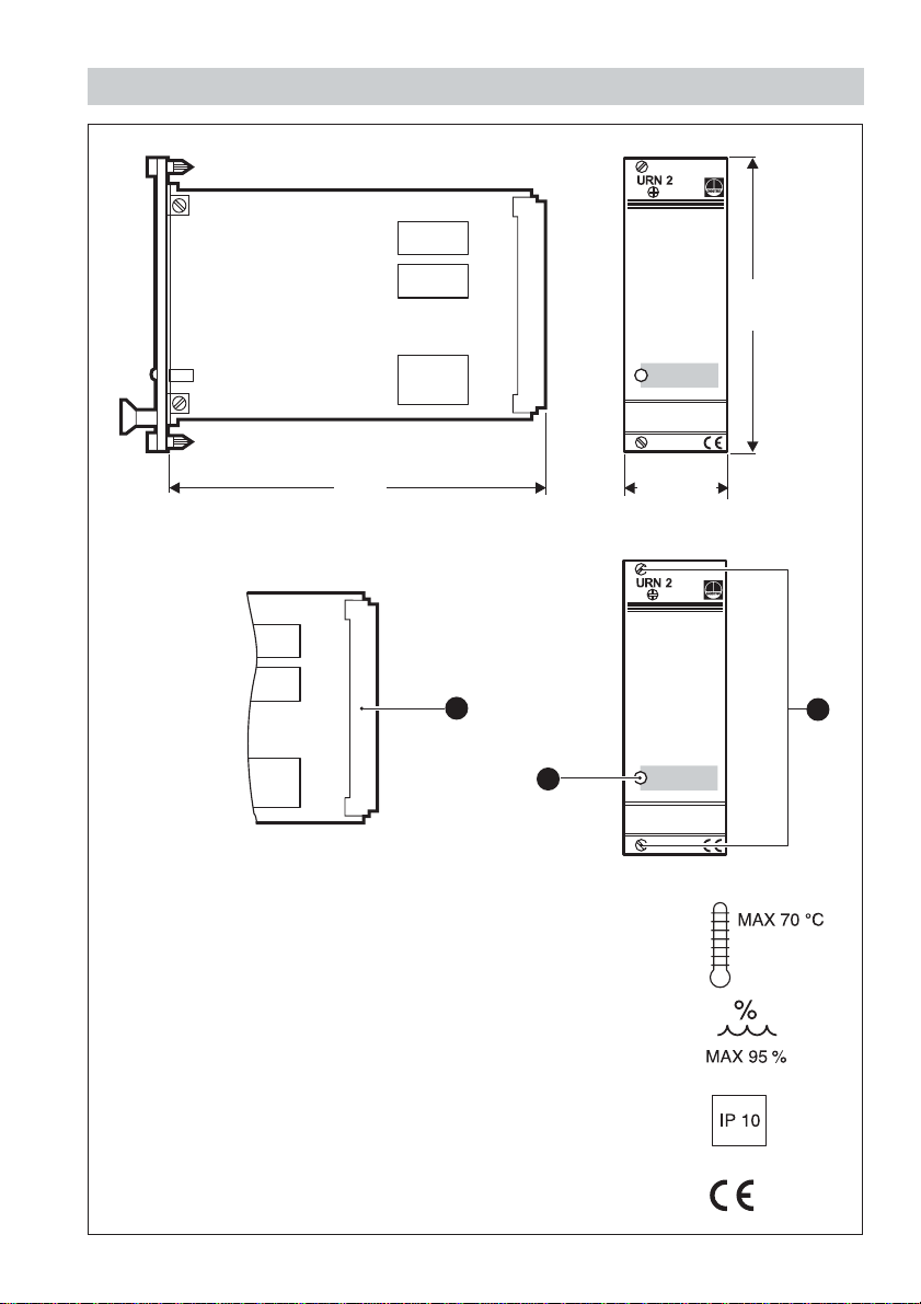
Dimensions/Parts Drawings
128.5
Fig. 1
169
30.01(6TE )
A
B
C
Fig. 2
3
Page 4

Key
A
32pole screw-type connector
B
C
OPERATION
LED
Fixing screws
4
Page 5

Important Notes
Usage for the intended purpose
Use power supply unit URN 2 only for the voltage supply of a maximum of four
switching controllers type NRS 2-4 or NRS 2-5 and the cycling timer PRS 9.
Safety note
The equipment may only be installed by qualified staff.
Qualified staff are those persons who – through adequate training in electrical
engineering, the use and application of safety equipment in accordance
with regulations concerning electrical safety systems, and first aid & accident
prevention – have achieved a recognised level of competence appropriate to
the installation and commissioning of this critical safety device.
Danger
The terminal strip of the URN 2 is live during operation. This presents the
danger of electric shock. Cut off power supply before opening the
equipment and before inserting or removing the 19" slide-in unit.
5
Page 6

Explanatory Notes
Scope of supply
URN 2, design “c”
1 Power supply unit type URN 2
2 Guide rails
1 32pole screw-type connector
1 Installation manual
URN 2, design “d”
1 Power supply unit type URN 2
1 Installation manual
System description
The power supply unit type URN 2 in combination with up to four level switches
types NRS 2-4 or NRS 2-5 and the cycling timer type PRS 9 can be used as part of
a controlled drainage system in power stations.
Function
The mains voltage is stepped down, rectified and provided as 24 V DC supply
voltage to the level switches NRS 2-4 and the cycling timer PRS 9.
Design
Design “c”
19" slide-in unit with guide rails and 32pole screw-type connector for installation in
19" magazine acc. to DIN 41494, part 5.
Design “d”
19" spare slide-in unit
6
Page 7

Technical data
Mains voltage
1115/230 V± 10 %, 50/60 Hz
1115/224 V ±10 %, 50/60 Hz (optional)
Power consumption
10 VA
Output
5x24 V DC
Indicator and adjustor
1 green LED
OPERATION
Protection
IP 10 to DIN EN 60529
Admissible ambient temperature
0°C to +70 °C
Case
19" slide-in unit with front panel to DIN 41494 par t 5 and rear 32 way Euro card
connector to DIN 41612 for installation onto 19" magazine.
Front panel: Aluminium
Wiring
via 32 pole screw-type connector at the back of the 19" magazine, max. conductor
size 1.5 mm
2
.
Internal fuse
Glass cartridge fine-wire slow-blow fuse 500 mA, replaceable
Weight
approx. 0.6 kg
7
Page 8

Installation
Design “c”/“d”
1. Install the guide rails and the screw-type connector in the 19" magazine.
2. Insert the 19" slide-in unit onto the guide rails until it hits the stop.
3. Tighten the fixing screws .
Attention
To provide sufficient ventilation, ensure a minimum spacing of 20 mm
between adjacent units.
Tools
■
Screwdriver for slotted screws, size 5, completely insulated according to VDE 0680.
C
8
Page 9
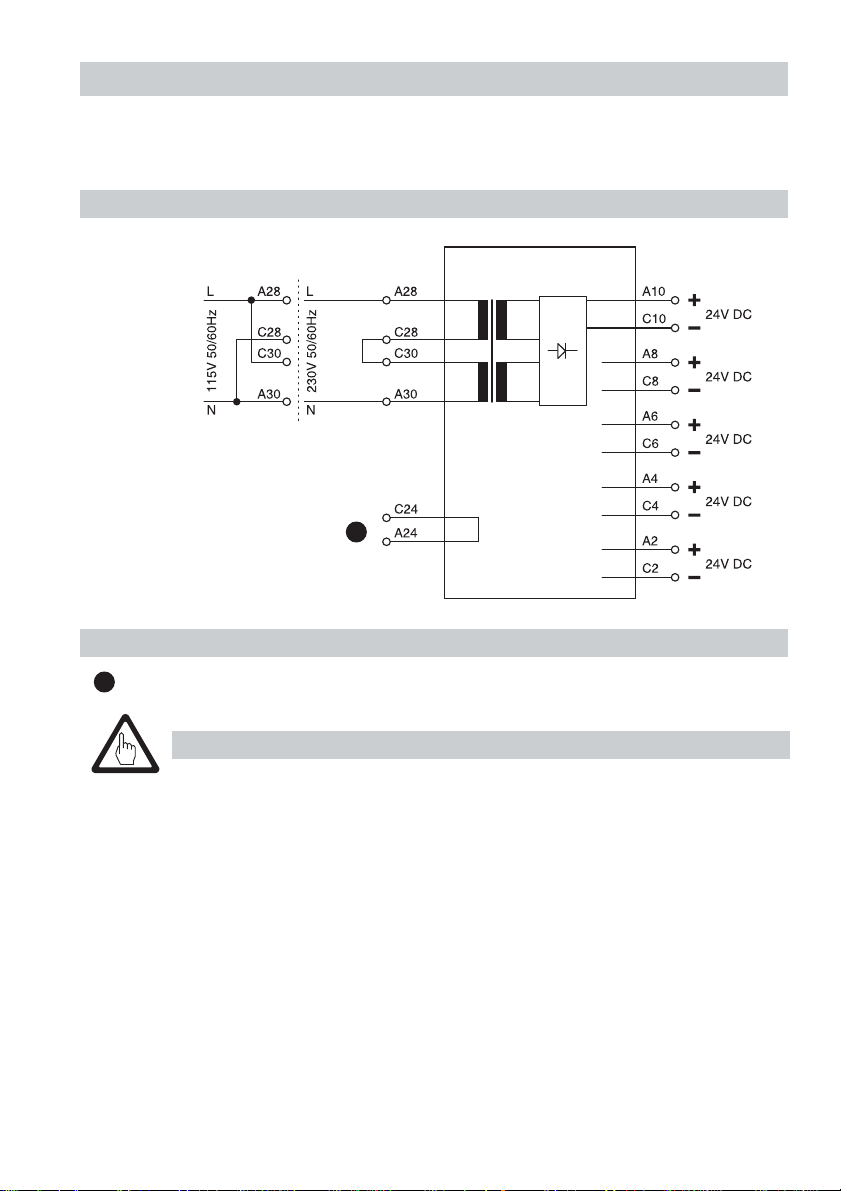
Wiring
Design “c”/“d”
Wiring is effected via the 32 pole screw-type connector.
Wiring diagram
1
Fig. 3
Key to wiring diagram
1
Test loop
Attention
■
Fuse supply cable with T 250 mA.
■
When switching off inductive loads, voltage spikes are produced that
may impair the operation of control systems.
Inductive loads should be provided with commercial arc suppressor
RC combinations, e.g. 0.1 µF/100.
9
Page 10
Commissioning
Warning
The terminal strip of the URN 2 is live during operation. This presents the
danger of electric shock. Cut off power supply before opening the
equipment and before inserting or removing the 19" slide-in unit.
Check wiring
1. Check whether the 19" slide-in unit has been properly inser ted into the magazine.
2. Check whether the equipment has been wired in conformity with the mains voltage.
Apply mains voltage
1. Switch on the mains voltage and check the equipment for power supply. The
Check output voltage
Check whether all five outputs feature an output voltage of 24 V DC.
B
LED functions as visual check.
10
Page 11
Annex
Danger
The terminal strip of the URN 2 is live during operation. This presents the
danger of electric shock. Cut off power supply before opening the
equipment and before inserting or removing the 19" slide-in unit.
Fault finding list
The LED is not illuminated after applying the mains voltage
Fault:
Remedy:
Fault:
Remedy:
B
The mains voltage has not been switched on.
Switch on the mains voltage. Check the 19" slide-in unit for correct installation.
The internal fuse is defective.
Remove the 19" slide-in unit and replace the internal fuse.
Not all outputs feature 24 V DC output voltage
Fault:
Remedy:
The internal circuitry is defective.
Replace the power supply unit.
If faults occur that are not listed above or cannot be corrected, please contact our
service centre or authorized agency in your country.
Declaration of conformity
We hereby declare that the equipment URN 2 conforms to the following European
guidelines:
■
LVD guideline 73/23/eec version 93/68/eec
■
EMC guideline 89/336/eec version 93/68/eec
which are based on the following harmonised standards:
■
LV standard EN 60947-5-1: 1991
■
EMC standard EN 50 081-2, EN 50 082-2
This declaration is no longer valid if modifications are made to the equipment
without consultation with us.
Bremen, 28th April 1997
GESTRA GmbH
Dr. Anno Krautwald
Dr. Christian P olitt
11
Page 12

GESTRA Gesellschaften · GESTRA Companies · Sociétés GESTRA · Sociedades Gestra · Società GESTRA
Vertretungen weltweit · Agencies all over the world · Représentations dans le monde entier · Representaciones en todo el mundo · Agenzie in tutto il mondo
España
GESTRA ESPAÑOLA S.A.
Luis Cabrera, 86-88
E-28002 Madrid
Tel. 003491/5152032
Fax003491/4136747; 5152 036
E-mail: gestra@gestra.es
Polska
GESTRA POLONIA Spolka zo.o.
Ul. Schuberta 104, P.O. Box 71
PL-80-172 Gdansk
Tel. 00 48 58 / 306 10 02 oder 306 10 10
Fax 00 48 58 / 3 06 10 03 oder 306 33 00
E-mail: gestra@gestra.pl
France Portugal
Flowserve Flow Control S.A. S.
10 Avenue du Centaure, BP 8263
F-95801 CERGY PONTOISE CEDEX
Tél. 00331/ 34432 6 60
Fax 00331/34432687
E-mail: gnation@flowserve.com
GESTRA PORTUGUESA VALVULAS
LDA.
Av. Dr. Antunes Guimarães, 1159
Porto 4100-082
Tel. 0035122/6 19 8770
Fax 0 0351 22/610757 5
E-mail: gestra@gestra.pt
Italia
Italgestra S.r.l.
Via Carducci 125
l-20099 Sesto San Giovanni (MI)
Tel. 003902/241012.1
Fax 0039 02/241012.460
E-mail: info@italgestra.it
®
GESTRA GmbH
Postfach 10 54 60
D-28054 Bremen
Münchener Str. 77
D-28215 Bremen
T el. +49 (0) 421 3503-0
Fax+49 (0) 421 3503-393
E-mail
gestra.gmbh@gestra.de
Internet www.gestra.de
A Unit of Flowserve Corporation
810401-01/702c · © 1997 GESTRA GmbH · Bremen · Printed in Germany
12
 Loading...